Out Door Application
The purpose of this page is to list all customization to be done on the NW configuration when it comes to outdoor deployment (AMARISOFT RAN combined with Radio head or External Amplifier/Antenna(e.g, DAS)) and list all tips to be known
Table of Contents
- Out Door Application
- Introduction
- Summary of the Tutorial
- Key Configuration Parameters
- Case 1 : Amarisoft RAN with TMA or DAS for Private Network
- Check Point 1 : Determine band/frequency
- Check Point 2 : Determine bandwidth
- Check Point 3 : Estimate the number of Concurrent UEs
- Check Point 4 : Tweak the broadcast reference power with External Amplifier Gain
- Case 2 : Amarisoft RAN with CPRI for Private Network
- Check Point 1 : Determine a Specific RRH
- Check Point 2 : Determine band/frequency
- Check Point 3 : Determine bandwidth
- Check Point 4 : Estimate the number of Concurrent UEs
- Check Point 5 : Tweak the broadcast reference power with External Amplifier Gain
- Basic Test and KPI
Introduction
Outdoor deployment of wireless networks, particularly using AMARISOFT RAN combined with radio heads or external amplifiers and antennas such as Distributed Antenna Systems (DAS), introduces unique technical challenges and configuration requirements compared to indoor or laboratory environments. AMARISOFT RAN, known for its software-based, flexible, and highly configurable approach to Radio Access Network (RAN) implementation, allows operators and engineers to tailor network behavior to suit the demands of outdoor scenarios, which often involve variable radio conditions, higher power levels, and complex coverage areas. At the architectural level, such deployments typically integrate the AMARISOFT software suite running on COTS (Commercial Off-The-Shelf) hardware with external RF components, creating a hybrid system that must be meticulously tuned for optimal performance, stability, and regulatory compliance. Key considerations include RF path configuration, synchronization, power calibration, antenna alignment, and environmental adaptations to cope with interference, multipath propagation, and physical obstructions. Mastery of these aspects not only ensures robust connectivity and user experience but also maximizes network efficiency and scalability in real-world outdoor settings. This tutorial provides a comprehensive guide to the necessary NW (Network) configuration customizations and expert tips essential for successful outdoor deployments, bridging the gap between theoretical knowledge and field-ready implementation.
-
Context and Background
- AMARISOFT RAN is a software-centric LTE/NR platform widely used for rapid prototyping, field trials, and commercial deployments.
- Outdoor deployment scenarios differ significantly from controlled test environments, requiring additional configuration for coverage, interference management, and hardware integration.
- Integration with radio heads, external amplifiers, and antennas introduces new parameters and dependencies that must be addressed at both the software and hardware levels.
-
Relevance and Importance
- Proper network customization is critical to achieving desired coverage, capacity, and regulatory compliance in outdoor environments.
- Failure to adapt the configuration may result in suboptimal performance, coverage gaps, or non-compliance with local spectrum regulations.
- This tutorial empowers engineers and network operators to effectively transition from indoor/lab to outdoor RAN deployments using AMARISOFT.
-
Learning Outcomes
- Gain an understanding of the key configuration changes required for outdoor AMARISOFT RAN deployments.
- Learn best practices for integrating external RF components such as radio heads, amplifiers, and DAS.
- Acquire practical tips for optimizing performance, managing interference, and ensuring network reliability.
- Develop the ability to troubleshoot common issues specific to outdoor wireless network setups.
-
Prerequisite Knowledge
- Familiarity with basic LTE/NR concepts and AMARISOFT RAN software operation.
- Understanding of RF fundamentals, including antenna types, power budgeting, and propagation effects.
- Experience with network configuration management and general wireless network deployment workflows.
Summary of the Tutorial
This tutorial provides a comprehensive overview of key configuration parameters and detailed test procedures for deploying Amarisoft RAN in outdoor private network settings, with two primary cases: integration with TMA/DAS and CPRI-based RRH architectures. The document also outlines foundational tests and KPIs for system validation.
- Case 1: Amarisoft RAN with TMA or DAS for Private Network
-
Check Point 1: Determine band/frequency
- Verify that the operating frequency is valid per 3GPP specification (500 MHz to 6.0 GHz supported). For standard bands, consult the relevant tutorial for finding valid options.
- If using a non-3GPP band, refer to custom frequency configuration guides.
- Be aware of common configuration errors related to frequency raster and band definition.
-
Check Point 2: Determine bandwidth
- Select bandwidth according to 3GPP-defined options for the chosen band.
- Refer to appropriate tutorials for bandwidth selection and be mindful of typical error messages related to frequency compatibility and SSB parameters.
-
Check Point 3: Estimate the number of Concurrent UEs
- Adjust physical resources for control channels based on the expected number of UEs.
- For LTE, consult tutorials on PUCCH configuration; for NR, review multi-UE parameter settings.
-
Check Point 4: Tweak the broadcast reference power with External Amplifier Gain
- Manually adjust the broadcast reference power in configuration to account for external amplifier gain, ensuring proper path loss calculations for UEs.
- Consult tutorials for identifying the correct broadcast message and information element, as well as procedures for manual adjustment.
- Use a spectrum analyzer (portable or SDR-based) to measure antenna output and verify correct power settings.
-
Check Point 1: Determine band/frequency
- Case 2: Amarisoft RAN with CPRI for Private Network
-
Check Point 1: Determine a Specific RRH
- Select an RRH confirmed to be compatible with Amarisoft CPRI interface.
- Note that only IQ SAP and Sync SAP are supported; configuration of basic RRH parameters (e.g., DL/UL Frequency, Cell Power) must be performed using the RRH manufacturer’s software. Consult the relevant tutorial for CPRI/RRH setup details.
-
Check Point 2: Determine band/frequency
- Follow the same frequency selection and validation procedures as in Case 1, with reference to 3GPP standards and custom configuration guides as needed.
- Review common error messages to avoid misconfiguration.
-
Check Point 3: Determine bandwidth
- Choose bandwidth according to 3GPP-defined lists for the selected band and consult tutorials for guidance.
- Be aware of frequent errors related to frequency raster and SSB compatibility.
-
Check Point 4: Estimate the number of Concurrent UEs
- Provision sufficient control channel resources by adjusting relevant parameters, referencing the same tutorials as in Case 1 for both LTE and NR.
-
Check Point 5: Tweak the broadcast reference power with External Amplifier Gain
- Manually compensate the broadcast reference power to reflect external amplifier gain, using spectrum analysis tools as described in Case 1.
- Follow the same procedure and reference materials for correct configuration and measurement.
-
Check Point 1: Determine a Specific RRH
- Basic Test and KPI Procedures
-
Test 1: Coverage Test
- Establish a basic UE connection and perform a simple connectivity check (e.g., continuous ping).
- Move the UE progressively farther from the cell or RRH antenna, observing the connectivity limit before disconnection occurs.
- Monitor radio link quality throughout the process using appropriate tutorials.
- Ignore throughput and BLER for this test; focus on maintaining connection.
-
Test 2: Minimize BLER
- Select multiple test points around the cell and measure BLER at each.
- Apply troubleshooting methods to minimize BLER, with reference to specialized tutorials.
- Throughput is not a concern during this test—objective is to reduce BLER only.
-
Test 3: Maximize Throughput
- Choose the location with optimal signal quality and minimal BLER (as determined from previous tests).
- Conduct PHY/MAC-level maximum throughput tests (with configuration guidance from referenced tutorials).
- Perform IP-level throughput tests using iperf, ensuring that PHY/MAC throughput meets expectations before proceeding.
-
Test 1: Coverage Test
The tutorial emphasizes the importance of understanding and carefully applying configuration parameters, methodically validating the system through staged test procedures, and leveraging reference materials for troubleshooting and optimization at each step.
Key Configuration Parameters
Followings are the list of configuration parameters to be carefully configured for all of the outdoor use cases. Most of these configuration parameters are used in Amarisoft sample configuration files that comes with installation package that is tested for lab setting. Since the environment and requirement for Outdoor setting is different from lab test and the requirement for outdoor setting would be different with each use cases, it is strongly recommended to have good understandings on the meaning and usage of these configuration parameters.
- Physical Resrouces for Uplink Control Channel : These parameters allows an increase in the number of simultaneous UEs but reduces the resources available for useful data, and therefore the throughput (Refer to the tutorials LTE_PUCCH and UESim_NR_MultiUE for the detailed usage)
- n1_pucch_sr_count (LTE)
- cqi_pucch_n_rb (LTE)
- short_pucch_an_rsc_count (NR)
- n_rb_max (NR)
- ue_count_max (NR)
- Dynamic Power Control : These parameters turn on the close loop power control To be disabled by default (to avoid the Near-Far Effect when multiple UE are connected
- Signal power level transmitted at the Antenna level : These parameters are used by the UE to calculate the path loss when DPC is set to false . When wrongly set , UE TX power can be inappropriate and generate interferences
- Measurement configuration criteria : These configurations should be adjusted depending on the radio condition at the cell edge . If the threshold are set too low , UE will get Radio link failure . On the other side , If they are too high ,UE will handover too often (Regarding the detailed usage of this configuration, refer to these tutorials : LTE_Measurement , LTE_HO_intra, LTE_HO_inter, NR_SA_HO )
- meas_config_desc (LTE)
- meas_config_desc(NR)
- TDD Config : These configurations are used to determine the ratio between UL slots(subframes) and DL slots(subframes). These configurations affect DL/UL throughput and RTT/Low Latency. For the detailed usage of these configuration, refer to NR_TDD_Pattern, Maximize Uplink Speed in 5G NR TDD, Improve RTT latency of NR gNB )
- uldl_config (LTE)
- sp_config (LTE)
- tdd_ul_dl_config (NR)
- Verbosity of traces per layer : Depending on these configurations, it can increase the CPU load and impact the RAN performances if signal or phy layer are set to debug by default
- Log Analysis : Amarisoft provides an excellent tool for logging and analysis. It can easily turn on/off specific log options on the fly and capture & analyze log visually and intuitively.
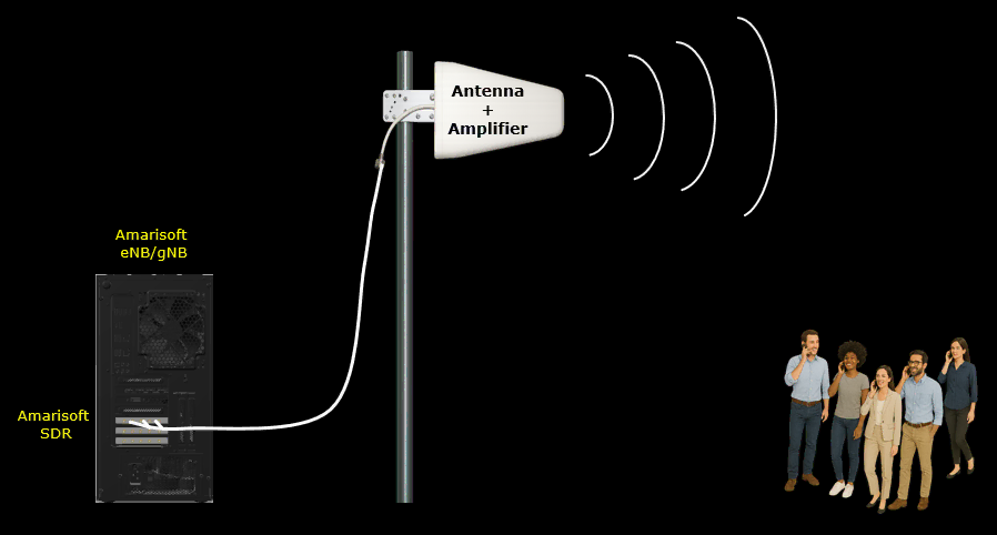
Case 1 : Amarisoft RAN with TMA or DAS for Private Network
One of the most typical use case of utilizaing Amarisoft RAN is to connect the callbox SDR card with external amplifier such as TMA (Tower mounted amplifier) or DAS (Distributed Antenna System). The purpose of this case is to provide a list of checkpoint and ponter to related documents to tutorial / wikis to help users quickly find the information.
Check Point 1 : Determine band/frequency
- If you want to use any band/frequency, make it sure that the frequency is valid in terms of 3GPP specification. Amarisoft Callbox support any frequency between 500 MHz to 6.0 GHz. You can pick any frequency within this ranage that are valid in terms of 3GPP.
- Refer to this tutorial on how to find a valid 3GPP band/frequency : NR SA Band Change (Please read through the entire tutorial since there are many tips scattered over the tutorial).
- If you want to use any band/frequency which is not defined by 3GPP, this is also possible.
- Refer to this tutorial on how to define and configure your own band and frequency which are not defined in 3GPP : NR_CustomFrequency , LTE_CustomFrequency
- Command Errors : There are some common mistake users often make. These mistakes various errors listed below.
Check Point 2 : Determine bandwidth
- According to 3GPP, you cannot pick any arbitrary bandwidth for any band. Each of the band has a specific list of bandwidth
- Refer to this tutorial on how to find a valid 3GPP bandwidth : NR SA BW Change (Please read through the entire tutorial since there are many tips scattered over the tutorial).
- Command Errors : There are some common mistake users often make. These mistakes various errors listed below.
Check Point 3 : Estimate the number of Concurrent UEs
- As the number of UEs that are connecting to a RAN (eNB, gNB), you need to reserve enough physical resources for control channels
- In case of LTE, refer to this tutorial to understand the meaning of PUCCH related parameters and how to set the value to accommodate the increased number of UEs : LTE_PUCCH
- In case of NR, refer to this tutorial to understand multi UE related parameters and how to set the value for them to accommodate the increased number of UEs : UESim_NR_MultiUE
Check Point 4 : Tweak the broadcast reference power with External Amplifier Gain
- The eNB/gNB sends its Tx power (Downlink Reference Power) in SIB message so that UE can calculate pathloss between eNB/gNB and the UE. Amarisoft set these reference power automatically based on tx_gain value. However, the increased power is not reflected automatically on power advertised in the SIB. So when you are using external amplifier, you need to compensate the broadcast reference power manually.
- Which broadcast message and which IE(Information Elements) carries the downlink reference power and how it is set by eNB/gNB ? : Refer to Cell Reference Power
- How to set LTE reference power manually : Refer to eNB with external power amplifier
- NOTE : During this process, it will be great help if you have spectrum analyzer to measure the power from the antenna. Portable/Handheld spectrum analyzer would be the best since you can check the spectrum anywhere around the cell, but non-portable/desktop type will be better than nothing. If you don't have any of dedicated spectrum analyzer (i.e, either portable nor desktop spectrum analyzer), you can use any SDR card on Amarisoft Callbox which is not being used for communication as spectrum analyzer. Refer to this tutorial for the details : SDR_SpectrumAnalyzer
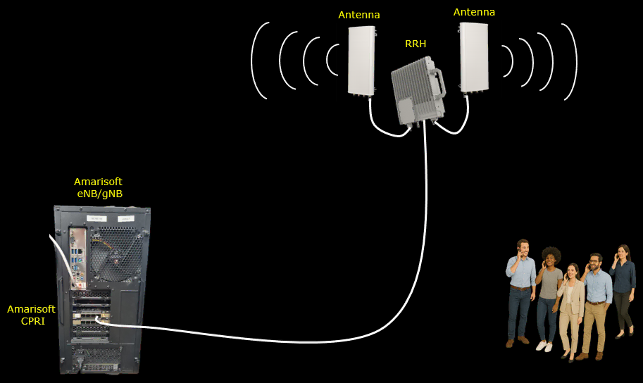
Case 2 : Amarisoft RAN with CPRI for Private Network
This is a common use case that are more and more frequently used recently. In this use case, users can extand the distance between Amarisoft RAN and TX/RX antenna via CPRI interface and expand cell coverage via an external RRH(Remote Radio Head).
Check Point 1 : Determine a Specific RRH
- Even though CPRI is a standard, there are so many different variations in terms of implementation. Not all RRH with CPRI interface would work with Amarisoft CPRI interface. You need to make it sure to select a specific RRH that is confirmed to work with Amarisoft CPRI card. Check with Amarisoft Sales for the specific CPRI/RRH product that is compatible with Amarisoft CPRI.
- Amarisoft CPRI support IQ SAP and Sync SAP only, it does not support C&M SAP. It means you need to configure some of RRH configuration(e.g, DL/UL Frequency, Cell Power etc) with RRH manufacturers configuration software (i.e, Amarisoft CPRI does not configure them automatically). Refer to this tutorial for the details : CPRI_RRH
Check Point 2 : Determine band/frequency
- If you want to use any band/frequency, make it sure that the frequency is valid in terms of 3GPP specification. Amarisoft Callbox support any frequency between 500 MHz to 6.0 GHz. You can pick any frequency within this ranage that are valid in terms of 3GPP.
- Refer to this tutorial on how to find a valid 3GPP band/frequency : NR SA Band Change (Please read through the entire tutorial since there are many tips scattered over the tutorial).
- If you want to use any band/frequency which is not defined by 3GPP, this is also possible.
- Refer to this tutorial on how to define and configure your own band and frequency which are not defined in 3GPP : NR_CustomFrequency , LTE_CustomFrequency
- Command Errors : There are some common mistake users often make. These mistakes various errors listed below.
Check Point 3 : Determine bandwidth
- According to 3GPP, you cannot pick any arbitrary bandwidth for any band. Each of the band has a specific list of bandwidth
- Refer to this tutorial on how to find a valid 3GPP bandwidth : NR SA BW Change (Please read through the entire tutorial since there are many tips scattered over the tutorial).
- Command Errors : There are some common mistake users often make. These mistakes various errors listed below.
Check Point 4 : Estimate the number of Concurrent UEs
- As the number of UEs that are connecting to a RAN (eNB, gNB), you need to reserve enough physical resources for control channels
- In case of LTE, refer to this tutorial to understand the meaning of PUCCH related parameters and how to set the value to accommodate the increased number of UEs : LTE_PUCCH
- In case of NR, refer to this tutorial to understand multi UE related parameters and how to set the value for them to accommodate the increased number of UEs : UESim_NR_MultiUE
Check Point 5 : Tweak the broadcast reference power with External Amplifier Gain
- The eNB/gNB sends its Tx power (Downlink Reference Power) in SIB message so that UE can calculate pathloss between eNB/gNB and the UE. Amarisoft set these reference power automatically based on tx_gain value. However, the increased power is not reflected automatically on power advertised in the SIB. So when you are using external amplifier, you need to compensate the broadcast reference power manually.
- Which broadcast message and which IE(Information Elements) carries the downlink reference power and how it is set by eNB/gNB ? : Refer to Cell Reference Power
- How to set LTE reference power manually : Refer to eNB with external power amplifier
- NOTE : During this process, it will be great help if you have spectrum analyzer to measure the power from the antenna. Portable/Handheld spectrum analyzer would be the best since you can check the spectrum anywhere around the cell, but non-portable/desktop type will be better than nothing. If you don't have any of dedicated spectrum analyzer (i.e, either portable nor desktop spectrum analyzer), you can use any SDR card on Amarisoft Callbox which is not being used for communication as spectrum analyzer. Refer to this tutorial for the details : SDR_SpectrumAnalyzer
Basic Test and KPI
Once you got familiar with all the basic configurations mentioned above and got the system working at the minimum level (e.g, just got a UE connected to your setup), I would suggest you to go through some basic test listed here.
Test 1 : Coverage Test
As the first test, you may want to check how much coverage your cell has. In this test,
- Just run the cell and get a UE connected and establish a simplest connection (e.g, doing continuous ping from Amarisoft Callbox or ping app on the mobile phone)
- Walk the phone away farther and farther away from the cell (RRH Antenna) and check how far you can go without getting disconnected.
- You may monitor radio link quality changes as you move away from the cell or move towards the cell. You may refer to this tutorial : NR_SA_RadioLinkQuality
- Do not care about throughput, do not care about BLER. It is good in this test as long as the call does not get disconnected.
Test 2 : Minimize BLER
The purpose of this test is to get yourself familiar with how to check BLER and how to troubleshoot to minimize BLER.
- Pick a few test point as you want around the cell and check BLER at each of the point
- Try to minimize the BLER : You may refer to this tutoria; : Fixing High BLER
- Do not care about throughput, just try to minimize BLER
Test 3 : Maximize Throughput
While performing previous test, you may learn the skills to find a spot that gives you the best signal quality and minimum BLER. If you still not familiar enough with the previous tests and troubleshoot technique, I would suggest to spend more time to practice on the previous tests. Unless you do the throughput test at the best spot, you would not get max throughput anyway.
- Pick the best spot (the spot that gives you the best radio link quality, minimum BLER)
- Try with PHY/MAC level max throughput test. Refer to this tutorial NR_SA_PhyTp (This tutorial is for NR, but the configuration for phy/mac throughput test are same for LTE and NR)
- Try with IP Throughput max throughput test with iperf. Refer to this tutorial Iperf (Theoretically the IP level test cannot be higher than PHY/MAC throughput. So make it sure that you get the expected throughput at PHY/MAC throughput first)