NR SA PHY Throughput
This tutorial shows you how to force Callbox to schedule physical channel (PDSCH / PUSCH) without any data coming from higher layer (IP data). This can be useful to check/troubleshoot radio link problems or to identify whether a low throughput issue is based on higher layer issue or phyical layer issue.
- Whenever you are getting the low throughput than you are expecting, I always recommend you try the PHY/MAC level throughput testing first.
- Whatever the conditions are, IP layer throughput can never be greater than PHY/MAC level throughput. Therefore, figuring out proper condition to achieve the expected PHY/MAC level throughput is the first step for all other throughput test.
- In this tutorial, I will let (force) the call box to schedule every possible DL / UL slot allowed by TDD UL/DL pattern with fixed number of RB, MCS.
Table of Contents
Introduction
The ability to diagnose and isolate throughput issues in wireless communication systems is critical for ensuring optimal performance and reliability. In the context of 4G and 5G radio access networks, the physical downlink shared channel (PDSCH) and physical uplink shared channel (PUSCH) are fundamental components responsible for user data transmission between the user equipment (UE) and the base station. This tutorial focuses on leveraging a Callbox—a versatile network simulator used in lab environments—to force the scheduling of PDSCH and PUSCH channels without the involvement of higher layer IP data. By bypassing the IP layer and directly configuring the scheduling of physical channels, engineers can effectively isolate and analyze radio link performance or identify whether reduced throughput originates from physical layer constraints or higher layer bottlenecks. The approach involves configuring the Callbox to maximize the usage of available transmission opportunities in both downlink and uplink directions in accordance with TDD (Time Division Duplex) UL/DL patterns, using fixed resource block (RB) and modulation and coding scheme (MCS) parameters. This method provides valuable insight into the achievable throughput at the PHY/MAC layer, forming the basis for benchmarking and troubleshooting within the radio access network architecture. Understanding this process is essential for radio engineers, testers, and network optimization specialists aiming to validate physical layer performance independently from higher layer protocol influences, thus ensuring a robust and methodical approach to wireless system testing and troubleshooting.
-
Context of the Technology
- PDSCH and PUSCH are key physical layer channels in LTE and 5G NR used for downlink and uplink user data transmission.
- The Callbox serves as a controlled test environment that emulates base station functions and enables fine-grained control over radio channel parameters.
- Throughput issues in wireless systems can originate from multiple layers; isolating the physical layer is crucial for effective troubleshooting.
-
Relevance and Importance of the Tutorial Topic
- Enables engineers to distinguish between PHY/MAC layer and higher layer (e.g., IP layer) throughput limitations.
- Provides a systematic approach to identify whether observed performance issues are due to radio link quality or upper layer protocol constraints.
- Supports efficient troubleshooting and optimization in lab testing and validation scenarios.
-
Learning Outcomes
- Understand how to configure a Callbox for forced scheduling of PDSCH/PUSCH without higher layer data.
- Gain the ability to conduct PHY/MAC level throughput tests, interpret results, and correlate them with overall system performance.
- Develop practical skills in isolating and diagnosing radio link issues and benchmarking PHY/MAC layer performance.
-
Prerequisite Knowledge and Skills
- Basic understanding of wireless communication principles, including LTE/5G NR architecture.
- Familiarity with physical layer concepts such as resource blocks (RB), modulation and coding schemes (MCS), and TDD UL/DL slot configuration.
- Experience with Callbox operation, configuration interfaces, or equivalent radio test equipment.
- Optional: Knowledge of RemoteAPI usage for dynamic test parameter adjustment.
-
Alignment with Tutorial Purpose and Scope
- This tutorial is designed to equip wireless engineers and testers with the skills needed to conduct robust PHY/MAC layer throughput tests, thereby enhancing their ability to troubleshoot and optimize radio access networks.
- The focus is on practical application, technical accuracy, and providing clear educational context for efficient laboratory testing workflows.
Summary of the Tutorial
This tutorial provides a procedure for low layer physical throughput testing in an NR Standalone (SA) environment, with a focus on configuring the gNB and UE for data generation at the physical layer. The overall methodology is designed to measure maximum possible physical layer throughput without engaging higher layer data traffic.
-
Test Setup:
- The test uses a SIM card provided with the system, and no complex IP layer setup is required for low layer testing.
- Reference is made to a configuration guide for users who wish to modify system parameters.
-
Key Configuration Parameters:
- Several gNB parameters are identified as critical for the test, such as force_dl_scheduler, force_full_bsr, pdsch_mcs, pdsch_fixed_rb_alloc, pusch_fixed_rb_alloc, and others.
- Configuration choices, such as starting RB, number of RBs allocated, and MCS value, directly impact the test outcome. Care must be taken to keep the allocated RBs within the limit of the configured bandwidth, and to set an appropriate MCS value matching the radio link condition.
-
Test 1: NR SA - BW 20 MHz
-
Purpose:
- To demonstrate configuration and operation of the gNB and UE for generating physical layer data in both uplink and downlink with a 20 MHz channel bandwidth, without any higher layer data traffic.
-
Configuration Steps:
- The test uses a modified configuration file gnb-sa-phyTp.cfg based on the sample gnb-sa.cfg.
- TDD is applied in the example, using NR_TDD_CONFIG = 2, but FDD can also be selected.
- NR_BANDWIDTH is set to 20 MHz.
- force_dl_scheduler: true ensures every DL slot is scheduled.
- pdsch_fixed_rb_start: 0 and pdsch_fixed_l_crb: 51 are set for full RB allocation for 20 MHz bandwidth.
- pdsch_mcs: 27 is used for each PDSCH transmission.
- force_full_bsr: true forces the gNB to schedule every possible UL slot. No specific RB or MCS parameters for PUSCH are set, so gNB handles these automatically.
- Users are cautioned to ensure that pdsch_fixed_rb_start + pdsch_fixed_l_crb does not exceed the maximum RBs for the selected bandwidth, and to set pdsch_mcs appropriately to avoid link failures.
-
Test Execution:
- Power on the UE and allow it to attach to the network.
- Observe high data rates on the physical layer without generating IP throughput (no need for tools like iperf or LteSimserver).
- If throughput is not optimal, users are advised to:
- Tune RF conditions, such as adjusting the distance between UE and antenna, optimizing TX/RX gain, and ensuring good quality RF connections, until maximum CQI and RI are achieved (CQI max is 15; RI max depends on MIMO configuration).
-
Purpose:
This procedure enables physical layer throughput assessment in a controlled environment, relying primarily on gNB parameter configuration and basic RF tuning, without requiring complex higher-layer or IP-level setup.
Test Setup
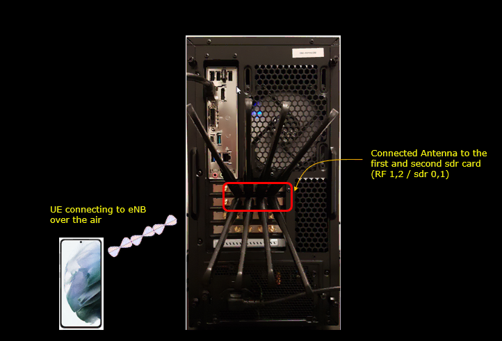
Test setup for this tutorial is as shown below. This is just for low layer testing, you may not need any complicated IP layer setup.
- SIM Card used in this tutorial is the one delivered with the system as it is.
- If you want to change the configuration, The tutorial Configuration Guide would help
Key Configuration Parameters
Followings are important configuration parameters for this tutorial. You may click on the items for the descriptions from Amarisoft documents.
- force_dl_scheduler
- force_full_bsr
- pdsch_mcs
- pdsch_fixed_rb_alloc
- pdsch_fixed_rb_start
- pdsch_fixed_l_crb
- pusch_fixed_rb_alloc
- pusch_fixed_rb_start
- pusch_fixed_l_crb
Test 1 : NR SA - BW 20 Mhz
The purpose of this test is to show how to configure the gNB to generate physical layer data in both uplink and downlink without any higher layer data. The channel bandwidth is configured to be 20Mhz. I will configure max (near max) for downlink and configure continuous scheduling for uplink but not necessarily max throughput. Uplink throughput will be varying depending gNB scheduling.
Configuration
I have used gnb-sa-phyTp.cfg which is copied and modified from gnb-sa.cfg.
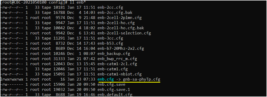
In gnb-sa-phyTp.cfg, I configured parameters as follows. In this test, TDD is applied but you can configure it to FDD if you like. You can select any specific tdd pattern with the parameter NR_TDD_CONFIG. I set NR_TDD_CONFIG to 2 which is one of default sample configuration provided by Amarisoft sample configuration. Channel bandwidth is set to 20Mhz by NR_BANDWIDTH.

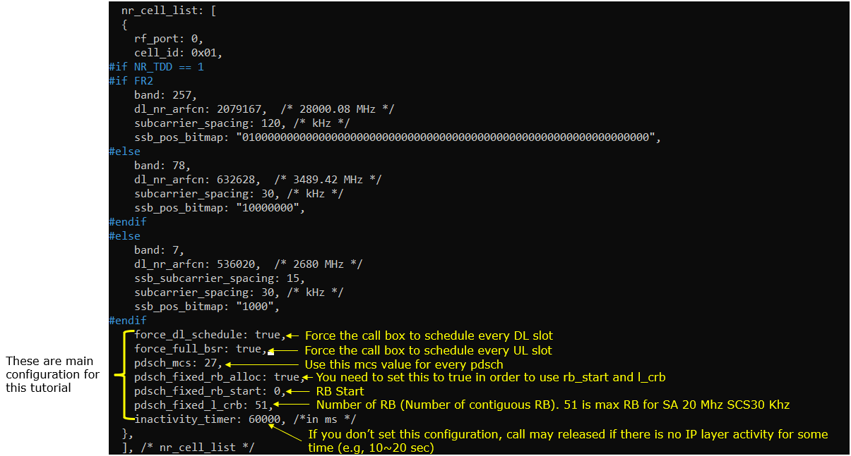
Followings are the key parameters for this tutorial. You should be careful so that pdsch_fixed_rb_start + pdsch_fxied_l_crb should not go over the maximum RBs for the channel bandwidth you specified. In addition, be careful about setting pdsch_mcs. If you put too high value for this parameter when radio link condition is not good enough, call drop may happen.
force_dl_scheduler : true is to force the gNB to schedule every DL slot. pdsch_fixed_rb_start:0 and pdsch_fixed_l_crb:51 is to configure the full RB allocation for the channel bandwidth 20Mhz. pdsch_mcs:27 is to set MCS to 27 for every PDSCH transmission.
force_full_bsr: true is to force gNB to schedule every possible UL slot. The number of RB and mcs will be set automatically by gNB in this test since I haven't set any pusch RB and mcs parameter setting here.
Perform the Test
Power on UE and let it attach. You would see high data rate without generating IP throughput (e.g, no iperf, no LteSimserver)
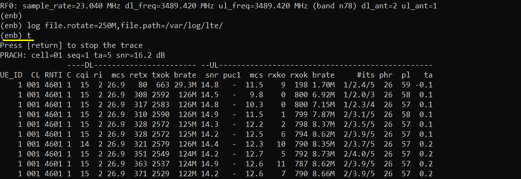
If you are not achieving high enough throughput(brate), you may try followings:
-
Tune RF condition (e.g, the distance between UE and Antenna, tx/rx gain, tighten the RF cable / connector if you are testing in conductive way) until you get max value for CQI and RI. 15 is the max for CQI and the max for RI varies depending on MIMO configuration (e.g, 2 is max RI for 2x2 MIMO, 4 is max RI for 4x4 MIMO etc)
-
Tune RF condition until you get near zero values for retx
-
Tune RF condition until you get good UL snr value (I think around 15 or higher is pretty reasonable)
-
If it is not possible to get the condition mentioned above, reduce the pdsch_mcs value in the configuration until you achieve the condition mentioned above (NOTE : If you decrease the mcs value, you cannot achieve the ideal max throughput)
-
If you see negative value or too small value on phr (power headroom report), tweak rx_gain values to have higher positive phr value
Test 2 : NR SA - BW 100 Mhz
The purpose of this test is to show how to configure the gNB to generate physical layer data in both uplink and downlink without any higher layer data. The channel bandwidth is configured to be 100Mhz. I will configure max (near max) for downlink and configure continuous scheduling for uplink but not necessarily max throughput. Uplink throughput will be varying depending gNB scheduling.
Configuration
I have used gnb-sa-phyTp.cfg which is copied and modified from gnb-sa.cfg.

In gnb-sa-phyTp.cfg, I configured parameters as follows. In this test, TDD is applied but you can configure it to FDD if you like. You can select any specific tdd pattern with the parameter NR_TDD_CONFIG. I set NR_TDD_CONFIG to 2 which is one of default sample configuration provided by Amarisoft sample configuration. Channel bandwidth is set to 100Mhz by NR_BANDWIDTH.

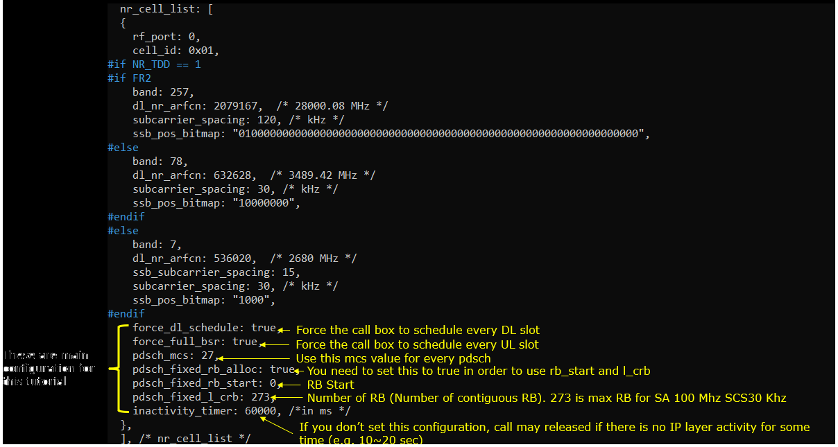
Followings are the key parameters for this tutorial. You should be careful so that pdsch_fixed_rb_start + pdsch_fxied_l_crb should not go over the maximum RBs for the channel bandwidth you specified. In addition, be careful about setting pdsch_mcs. If you put too high value for this parameter when radio link condition is not good enough, call drop may happen.
force_dl_scheduler : true is to force the gNB to schedule every DL slot. pdsch_fixed_rb_start:0 and pdsch_fixed_l_crb:273 is to configure the full RB allocation for the channel bandwidth 100Mhz. pdsch_mcs:27 is to set MCS to 27 for every PDSCH transmission.
force_full_bsr: true is to force gNB to schedule every possible UL slot. The number of RB and mcs will be set automatically by gNB in this test since I haven't set any pusch RB and mcs parameter setting here.
Perform the Test
Power on UE and let it attach. You would see high data rate without generating IP throughput (e.g, no iperf, no LteSimserver)

If you are not achieving high enough throughput(brate), you may try followings:
-
Tune RF condition (e.g, the distance between UE and Antenna, tx/rx gain, tighten the RF cable / connector if you are testing in conductive way) until you get max value for CQI and RI. 15 is the max for CQI and the max for RI varies depending on MIMO configuration (e.g, 2 is max RI for 2x2 MIMO, 4 is max RI for 4x4 MIMO etc)
-
Tune RF condition until you get near zero values for retx
-
Tune RF condition until you get good UL snr value (I think around 15 or higher is pretty reasonable)
-
If it is not possible to get the condition mentioned above, reduce the pdsch_mcs value in the configuration until you achieve the condition mentioned above (NOTE : If you decrease the mcs value, you cannot achieve the ideal max throughput)
-
If you see negative value or too small value on phr (power headroom report), tweak rx_gain values to have higher positive phr value
Additional Information
It is observed that ping delay improves much (delay being shortened) comparing to default scheduling. It appears that UL timing (ping reply) would be improved since SR/BSR procedure (one of the possible delay factor) would not be necessary and UE can transmit PUSCH as soon as it has data to send
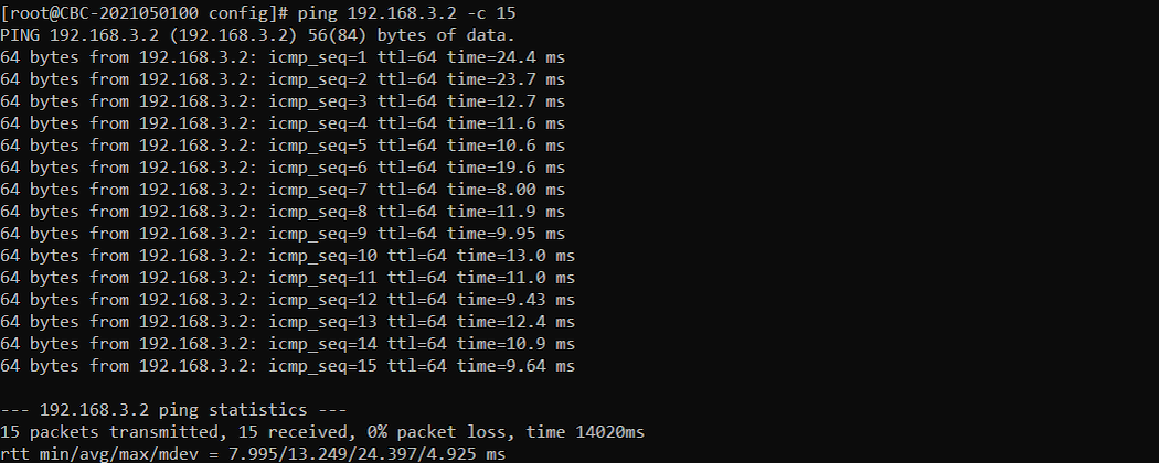
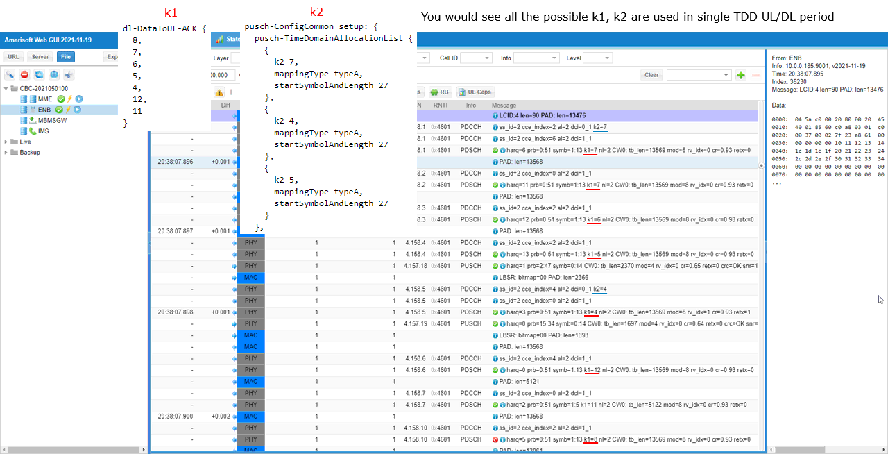
You can confirm that all the possible k1 and k2 set in RRC are used in PHY layer traffic implying that all possible DL and UL slots are scheduled.
