NR Custom Frequency
This tutorial show you how to define NR band and earfcn which is not defined in 3GPP. Amarisoft SDR can roughly support any frequency between 500Mhz and 6 Ghz without any external Up/Down converter. So you can set any frequency within that range regardless of whether it is defined in 3GPP or not.
If any specific frequency and band is defined in 3GPP, you can just specify the band and earfcn as specified in 3GPP. But if you want to use any other frequency region which are not defined in 3GPP, you can define your own band and earfcn as will be shown in this tutorial.
Table of Contents
- NR Custom Frequency
Introduction
The ability to configure custom NR (New Radio) bands and EARFCN (E-UTRA Absolute Radio Frequency Channel Number) values is critical for advanced wireless research, prototyping, and non-standard deployments. While the 3GPP specifications define a comprehensive set of bands and corresponding frequency-channel mappings for NR and LTE systems, there are numerous scenarios—such as private networks, academic research, or regulatory testbeds—where operators and engineers must utilize frequency ranges not officially standardized by 3GPP. Amarisoft SDR (Software Defined Radio) platforms offer a high degree of flexibility, enabling users to define and operate on virtually any frequency between 500 MHz and 6 GHz without the need for external up/down converters. This allows for rapid experimentation, spectrum agility, and innovative use-cases beyond conventional commercial deployments. In standard-compliant setups, users simply select the desired band and EARFCN as per 3GPP documentation; however, for experimental or non-standard frequencies, Amarisoft’s configuration tools allow users to create custom bands and channel mappings, effectively extending the capabilities of NR and LTE systems. This tutorial provides a detailed, step-by-step guide on how to define your own NR band and EARFCN values that fall outside the current 3GPP specifications, equipping you with the knowledge to exploit the full frequency range supported by Amarisoft SDR. Understanding and implementing these configurations expands the scope of what is possible with modern SDR platforms and empowers users to innovate within the wireless communications ecosystem.
-
Context and Scope
- Custom NR band and EARFCN definition is essential for test, research, and custom deployment scenarios where standardized 3GPP band allocations are insufficient.
- Amarisoft SDR platforms support flexible frequency configuration between 500 MHz and 6 GHz, allowing diverse use cases without hardware modifications.
- This tutorial focuses on the configuration steps and practical considerations for defining non-standard NR bands and channel mappings, specifically within the Amarisoft SDR environment.
-
Relevance and Importance
- Enables wireless engineers and researchers to utilize non-standard frequency ranges for prototyping, regulatory testing, and private network deployments.
- Facilitates rapid experimentation and spectrum agility, crucial for emerging wireless technologies and non-traditional network setups.
- Empowers users to maximize the capabilities of SDR platforms by overcoming the limitations of standard band definitions.
-
Learning Outcomes
- Gain a comprehensive understanding of NR band and EARFCN mapping principles.
- Acquire practical skills in configuring Amarisoft SDR to operate on custom frequency bands.
- Learn the distinction between standard-compliant and custom frequency configurations.
- Develop proficiency in extending radio system capabilities beyond official 3GPP specifications.
-
Prerequisite Knowledge and Skills
- Familiarity with NR/LTE concepts, including bands, frequency allocation, and channel mapping.
- Basic understanding of Amarisoft SDR platform operations and configuration processes.
- General knowledge of wireless communications principles and regulatory requirements.
- Ability to interpret and apply configuration documentation for SDR environments.
-
Tutorial Alignment
- This tutorial is designed for wireless engineers, researchers, and advanced practitioners seeking to extend their system’s operational frequency range.
- It provides a structured, hands-on approach that aligns with Amarisoft’s flexible SDR architecture and supports both NR and LTE custom frequency use-cases.
- Reference to related LTE custom frequency configuration is provided for users interested in multi-standard experimentation.
Summary of the Tutorial
This tutorial outlines the procedures for configuring and testing a custom NR (New Radio) frequency band using Amarisoft software, with an emphasis on test setup, configuration steps, and verification methods.
-
Test Setup
- Commercial UEs are not used since they do not support non-3GPP bands and earfcn.
- The test setup relies on a callbox and SDR-based test equipment capable of supporting custom frequency bands.
-
Key Configuration Parameters
- Configure key parameters such as custom_freq_band, defining the band number, frequency range (DL/UL min/max), subcarrier spacing, frequency raster, and other relevant band settings.
- Reference is made to Amarisoft documentation for detailed descriptions of each parameter.
-
Configuration Procedure
- Start by copying and modifying the gnb-sa.cfg configuration file to create a custom configuration (e.g., gnb-sa-custom-band.cfg).
- Add a TDD flag option as required for the test scenario.
- Define a custom band and its frequency range within the configuration file. Note that ARFCN mapping to frequency is handled by a 3GPP-defined formula and cannot be set arbitrarily.
- Specify dl_nr_arfcn and ul_nr_arfcn values within the allowed custom frequency range.
- Utilize external tools such as the 5G NR ARFCN Calculator to assist with ARFCN and frequency mapping.
-
Test Procedure: Run and Check
- Run the LTE/NR service and access the eNB screen mode.
- Verify that the configured band and frequency are correctly displayed in the default (enb) screen output.
- Use the [cell phy] command to confirm the ARFCN configuration.
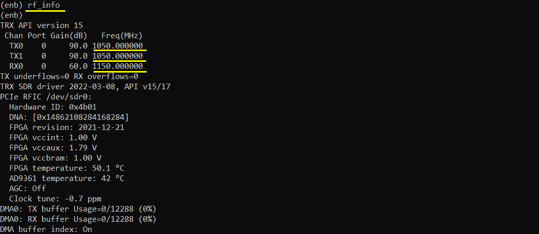
- Check the frequency using the rf_info command for further verification.
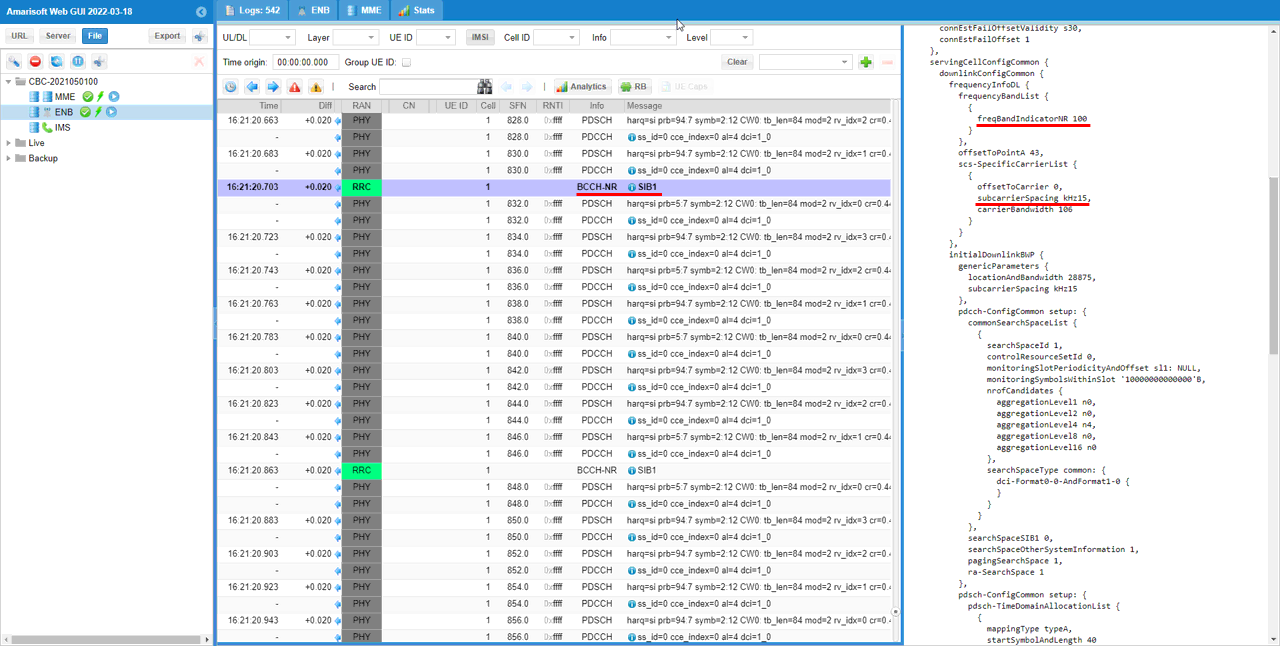
- Confirm that the custom band information is broadcast by checking the SIB1 message, specifically verifying that frequencyBandIndicatorNR and subcarrierSpacing match the configuration.
The tutorial focuses on setting up and verifying a custom NR frequency band configuration on the Amarisoft platform, emphasizing the importance of proper parameter configuration and step-by-step verification through system commands and broadcast messages.
Test Setup
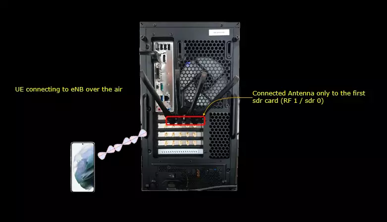
I would not use the UE here since commercial UE would not support non-3GPP band and earfcn.
Key Configuration Parameters
Followings are important configuration parameters for this tutorial. You may click on the items for the descriptions from Amarisoft documents.
Configuration
I am using gnb-sa-custom-band.cfg which is copied and modified from gnb-sa.cfg

I added a new option to the NR_TDD flag to support a custom NR FDD configuration. In addition to the existing values 0 for NR FDD and 1 for NR TDD, NR_TDD can now be set to 2 to select NR FDD Custom mode. This option will be used in this tutorial to configure an NR FDD frequency that is outside the standard 3GPP NR band definitions.

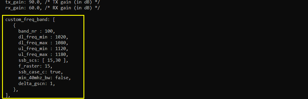
Then I defined a custom NR band using the custom_freq_band block. In this example, band_nr is set to 100, with the downlink frequency range defined by dl_freq_min = 1020 MHz and dl_freq_max = 1080 MHz, and the uplink frequency range defined by ul_freq_min = 1120 MHz and ul_freq_max = 1180 MHz.
Note that there is no explicit NR-ARFCN definition in this block. For a custom frequency configuration, the NR-ARFCN cannot be mapped arbitrarily to a frequency. The relationship between frequency and NR-ARFCN follows the predefined 3GPP NR-ARFCN mapping formula. Therefore, the custom_freq_band block defines the band number and supported frequency ranges, while the corresponding NR-ARFCN is determined from the selected frequency according to the 3GPP mapping rule. (
The ssb_scs parameter is set to [15, 30], allowing SSB operation with 15 kHz or 30 kHz subcarrier spacing. The f_raster parameter is set to 15, ssb_case_c is enabled, min_40mhz_bw is disabled, and delta_gscn is set to 1. A tool such as the 5G-Tools NR-ARFCN calculator can be useful for checking the mapping between the desired frequency and its corresponding NR-ARFCN.
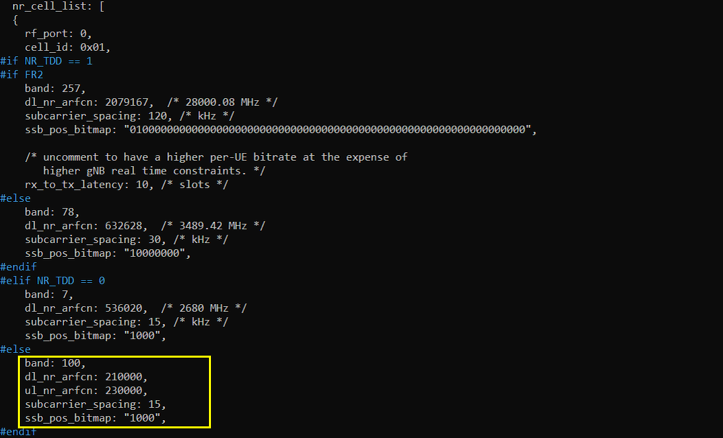
Then I configured the NR cell to use the custom band defined above. The band parameter is set to 100, matching the band_nr value in the custom_freq_band block. Since this is an FDD configuration, the downlink and uplink frequencies are specified separately using dl_nr_arfcn and ul_nr_arfcn.
In this example, dl_nr_arfcn is set to 210000 and ul_nr_arfcn is set to 230000. These NR-ARFCN values must correspond to frequencies that fall within the previously configured custom downlink range of 1020–1080 MHz and uplink range of 1120–1180 MHz. The subcarrier_spacing parameter is set to 15 kHz, and ssb_pos_bitmap is set to "1000".
The important point is that the custom_freq_band block defines the allowable frequency ranges, while dl_nr_arfcn and ul_nr_arfcn select the actual operating downlink and uplink frequencies within those ranges according to the standard NR-ARFCN-to-frequency mapping.
Run and Check
Since commercial UEs normally support only standardized 3GPP bands, I cannot demonstrate this custom-band configuration using a commercial UE. However, the configured custom band, operating frequencies, and NR-ARFCNs can still be verified directly from the Amarisoft LTE service.
Start the LTE service and switch to the (enb) screen mode. The startup output confirms that RF0 is operating with dl_freq = 1050.000 MHz and ul_freq = 1150.000 MHz using band 100. These frequencies are within the custom downlink range of 1020–1080 MHz and uplink range of 1120–1180 MHz configured earlier.
Then run the cell phy command. The PHY status shows band n100 with dl_nr_arfcn = 210000 and ul_nr_arfcn = 230000, confirming that the custom band and NR-ARFCN configuration has been applied correctly. The output also shows a 20 MHz bandwidth and 15 kHz subcarrier spacing.

As with the default output on the (enb) screen, you can also verify the actual RF frequencies using the rf_info command. In this example, TX0 and TX1 are both operating at 1050 MHz, confirming the configured downlink frequency, while RX0 is operating at 1150 MHz, confirming the configured uplink frequency.
This provides a direct check at the SDR level that the custom NR band configuration has resulted in the expected 1050 MHz downlink and 1150 MHz uplink RF frequencies.
Lastly, you can verify that the custom band information is actually broadcast in SIB1. In the WebGUI, select the SIB1 message and check the servingCellConfigCommon information. In this example, freqBandIndicatorNR is shown as 100, which matches the custom band configured with band_nr = 100. The subcarrierSpacing field is shown as kHz15, which also matches the configured 15 kHz subcarrier spacing.
This confirms that the custom band configuration is not only applied internally by the gNB, but is also advertised over the air through SIB1 using the configured band number and subcarrier spacing.