Iperf
The purpose of this tutorial is to show you how to do throughput test with iperf2. iperf would be the tool that have been used the most widely for IP throughput test in various situation. For some specific application, iperf may not be good enough and you may need some dedicated packet generator, but for a lot of ordinary IP throughput test as we do in wireless communication iperf would still be the most widely used tool. There are two types of iperf we can easily get : iperf2 and iperf3.In LTE days, as far as I recall, iperf2 was used dominatly and I see more and more users are using iperf3 more recently and in 5G. But which tool is better is still in debates and seems to be up to personal preferences.
In this tutorial, I used iperf2 but you can use iperf3 as well. Just a small adjustment for comman and options. For relatively low throughput I don't think it would not take much effort to achieve the rate you expected, but for very high throughput (like 1Gbps or higher), it would take some time and effort to figure out proper option values for iperf. Unfortunately it would not be possible to provide the best options and option values that fits for every situation. A set of iperf options that worked well with my setup would not work well with your setup. Therefore, you should anticipate that you should spend a considerable amount of time and effort to figure out the set of iperf options that works with your own setup.
At the earily stage of the test setup, it would be helpful for you to visit the Offical sites for iperf and check out some documents published there.
It is assumed that you are familiar with the basic operations of the callbox and I would not explain about the very basic operations of callbox. If you are not familiar with the basic operation of the callbox, refer to other tutorials like LTE Attach, SA setup, NSA setup etc.
Table of Contents
Introduction
In modern networking environments, evaluating and optimizing IP throughput is crucial for ensuring robust, high-performance communication across wired and wireless systems. iperf2 stands as one of the most widely adopted open-source tools for conducting reliable IP throughput testing, providing detailed insights into network bandwidth, latency, and overall performance. Originally developed for academic and enterprise environments, iperf2 enables users to generate TCP and UDP traffic between a client and server, allowing for granular control over test parameters such as data rate, protocol, buffer sizes, and parallel streams. Its architecture adopts a client-server model, where the client initiates connections to one or more servers, facilitating both unidirectional and bidirectional testing scenarios. In wireless communication domains such as LTE and 5G, iperf2 remains indispensable for validating end-to-end data transmission capabilities, diagnosing network bottlenecks, and tuning system parameters for optimal throughput. While iperf2 and its successor, iperf3, share similar core functionalities, subtle differences in command syntax, feature sets, and performance characteristics have led to ongoing debates regarding their relative merits. This tutorial focuses on iperf2, guiding users through practical throughput testing workflows, highlighting key configuration options, and addressing common challenges encountered in real-world deployments. By leveraging iperf2, network engineers and testers can systematically assess and enhance the efficiency of their data paths, ensuring systems meet the demanding requirements of contemporary IP-based communication.
-
Context and Scope
- iperf2 is a specialized tool for generating and measuring IP traffic across network links, widely used in both research and industry for performance validation.
- The tutorial is situated in the context of wireless communication testing, particularly in environments utilizing LTE and 5G technologies.
- It addresses practical aspects of configuring and running iperf2 for throughput testing, rather than exploring theoretical network optimization or maximum attainable throughput.
-
Relevance and Importance
- Throughput testing is fundamental for network engineers, QA testers, and researchers aiming to ensure optimal data transfer rates and identify limitations in network infrastructure.
- iperf2 provides a flexible and extensible platform for simulating realistic traffic patterns and analyzing performance under various conditions.
- Mastering iperf2 equips practitioners with the skills needed to diagnose network issues, validate hardware/software configurations, and benchmark against industry standards.
-
Learner Outcomes
- Develop a comprehensive understanding of iperf2’s architecture, operational modes, and command-line options.
- Gain hands-on experience in setting up and executing throughput tests between client and server systems.
- Learn to interpret throughput results and troubleshoot common issues related to high-speed data transfer.
- Acquire best practices for configuring iperf2 parameters to suit different network environments and test objectives.
-
Prerequisite Knowledge and Skills
- Familiarity with basic network concepts such as TCP/IP, client-server architecture, and network interfaces.
- Experience with command-line operations on Linux or Windows platforms.
- Understanding of the test environment, including callbox operation, if applicable.
- Basic knowledge of the underlying wireless or wired communication system being tested (e.g., LTE/5G test setups).
Summary of the Tutorial
This tutorial covers multiple test procedures for verifying IP traffic (using iperf) over different Radio Access Technologies (RATs) and IP versions, utilizing both UE simulators and commercial mobile devices as Devices Under Test (DUT). The focus is on correct configuration matching, stepwise setup, and verification processes to ensure successful connectivity and throughput measurement.
-
Test 1: UE Sim - NR SA, IPv4
- Ensure correct configuration matching between UE simulator and Callbox, including SIM and network parameters.
- On UE Sim, use a specified configuration file (e.g., ue-nr-sa-50M-iperf.cfg), and on Callbox, configure the gNB and MME using corresponding files.
- Verify cell configuration (frequency, band, bandwidth, MIMO, etc.) on both sides.
- Power on the UE, attach to the cell, and confirm IP address allocation.
- Ensure network namespaces for UE instances are established.
- Run iperf in server mode on the UE Sim and in client mode on the Callbox.
- Adjust tx_gain and rx_gain as needed for optimal throughput.
- Verify throughput using iperf's 't' command and tune radio link conditions as necessary.
-
Test 2: Commercial Mobile Phone - NR SA, IPv4
- Prepare the test environment with a commercial mobile phone as DUT and configure the Callbox using a specific configuration file (e.g., gnb-sa-50M-sdr0.cfg).
- Install and prepare an iperf application on the commercial UE.
- Check and confirm cell parameters (frequency, band, bandwidth, MIMO, etc.).
- Power on the UE, attach to the cell, and verify IP address assignment.
- Use the MME to verify the UE has obtained at least one IPv4 address.
- Start the iperf server on the UE and ensure the server is listening.
- On Callbox, initiate a continuous ping to the UE to maintain the RRC connection and prevent idle state.
- Transmit UDP traffic from Callbox to UE using iperf client.
- Verify throughput on both UE and Callbox, and adjust radio link conditions for optimal performance.
-
Test 3: UE Sim - LTE, IPv4v6
- Ensure configuration alignment between UE Sim and Callbox for both IPv4 and IPv6 support.
- Use configuration files (ue-lte-ipV4V6.cfg on UE Sim, enb.default.cfg on Callbox eNB, and mme-ims-internet-ipv4v6.cfg on MME).
- Confirm cell parameters and that the Callbox assigns the correct IPv6 addresses as per configuration.
- Power on UE and ensure attach procedure completes successfully.
- Verify on Callbox MME that both IPv4 and IPv6 addresses are allocated to the UE (noting only the network prefix may be displayed for IPv6).
- Check UE Sim for successful IP address allocation and presence in the network namespace.
- Verify the UE's network interface has the proper IPv6 address using ifconfig.
- Perform a ping test from Callbox to UE to confirm connectivity.
- Run iperf in UDP server mode with IPv6 support on UE Sim and in UDP client mode on Callbox.
- Confirm that IP traffic flows correctly between Callbox and UE.
-
Test 4: UE Sim - LTE, IPv6 Only
- Configure UE Sim and Callbox for IPv6-only operation, ensuring all relevant parameters are set for IPv6 and not IPv4.
- Use appropriate configuration files (ue-lte-ipV6.cfg on UE Sim, enb.default.cfg on eNB, mme-ims-internet-ipv6.cfg on MME).
- Confirm cell setup and that Callbox assigns IPv6 addresses as configured.
- Power on UE and ensure complete attach procedure with IPv6 address allocation.
- On UE Sim, verify network namespace and correct IPv6 address assignment using ifconfig.
- Run a connectivity test by pinging UE from Callbox.
- Start iperf server on UE Sim with IPv6 support and iperf client on Callbox.
- Validate successful IP traffic reception on UE Sim.
The tutorial emphasizes the importance of configuration matching between UE and test network, systematic verification of connectivity and IP address allocation, and the use of iperf for throughput validation under various RAT and IP version scenarios.
Test 1 : UE Sim - NR SA, IPv4
This is the most basic test for iperf based on IPv4 and using UEsim as DUT. In this test, I used NR SA as RAT (Radio Access Technology), but type of RAT is not important. You can use any RAT (e.g, LTE, NR NSA) in the same way as explained here.
Test Setup
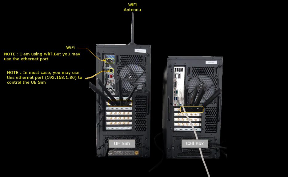
Configuration
An important thing in using UE sim is to do proper matching between UE sim configuration and Call box configuration
If you use other Network (e.g, other network simulator or real network), you have to make it sure to configure UE sim according to the settings on network side.
On UEsim, I used ue-nr-sa-50M-iperf.cfg which is copied and modified from ue-nr-sa.cfg

On Callbox enb, I used gnb-sa-50Mhz.cfg which is copied and modified from gnb-sa.cfg.
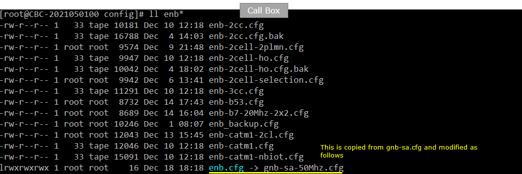
On Callbox mme, I used mme-ims.cfg as it is.
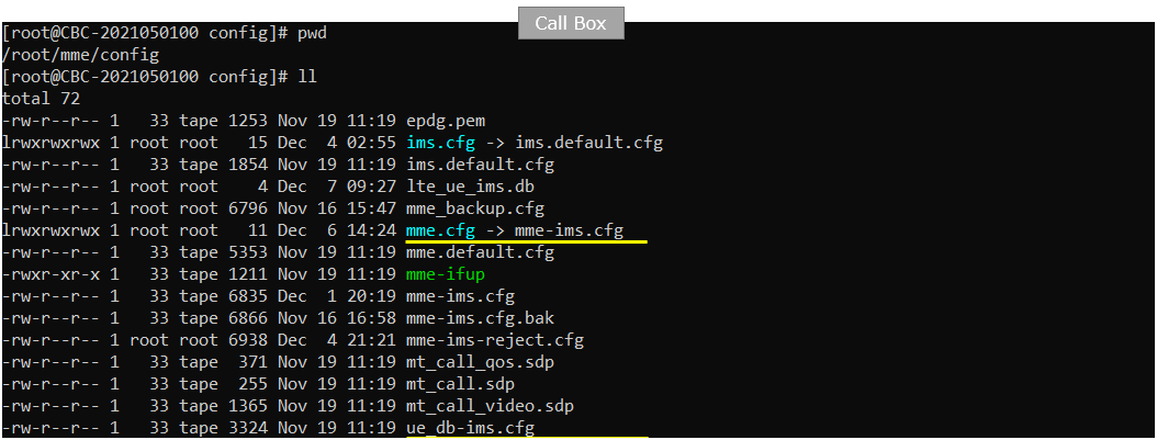
Following is the configuration on Callbox (gnb-sa-50Mhz.cfg). You can specify TDD/FDD(NR_TDD), MIMO(N_ANTENNA_DL) and bandwidth(NR_BANDWIDTH) etc but these details is not so imporant in this test.
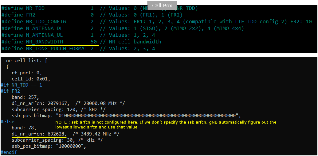
You would see following in /root/mme/config/mme-ims.cfg file on Callbox

In this tutorial, following SIM information will be used. Make it sure to configure the same parameters on UE side as well. (NOTE : this is the contents of ue_db-ims.cfg)

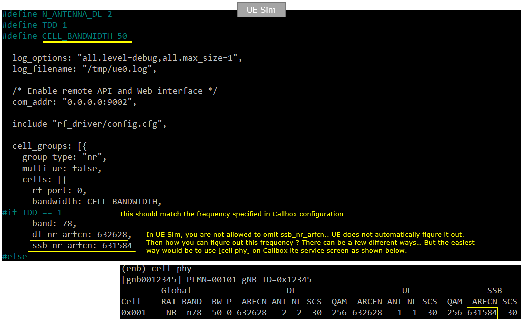
Following is the configuration on UEsim(ue-nr-sa-50M-iperf.cfg )

Peform the Test
Check cell configuration and confirm that they (frequency, band, bandwidth, mimo etc) are configured as you intented

Power on UE and Get UE attached to the cell.

Figure out IP address that is allocated to UE

Check if the network name space for each UE instances on UE is established.

Run the following command on UE sim (IP traffic reciever)

Run the following command on Callbox(IP traffic sender)
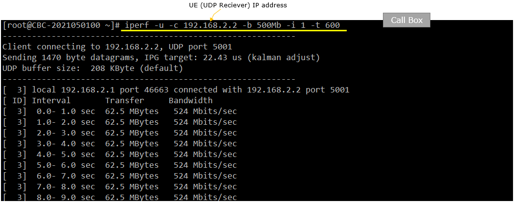
Followings are tx_gain, rx_gain on UE Sim and Callbox to achieve the throughput shown in next slide. But this specific value is only for the specific setup used in my test environment. The optimal value will vary depending on each specific test setup.


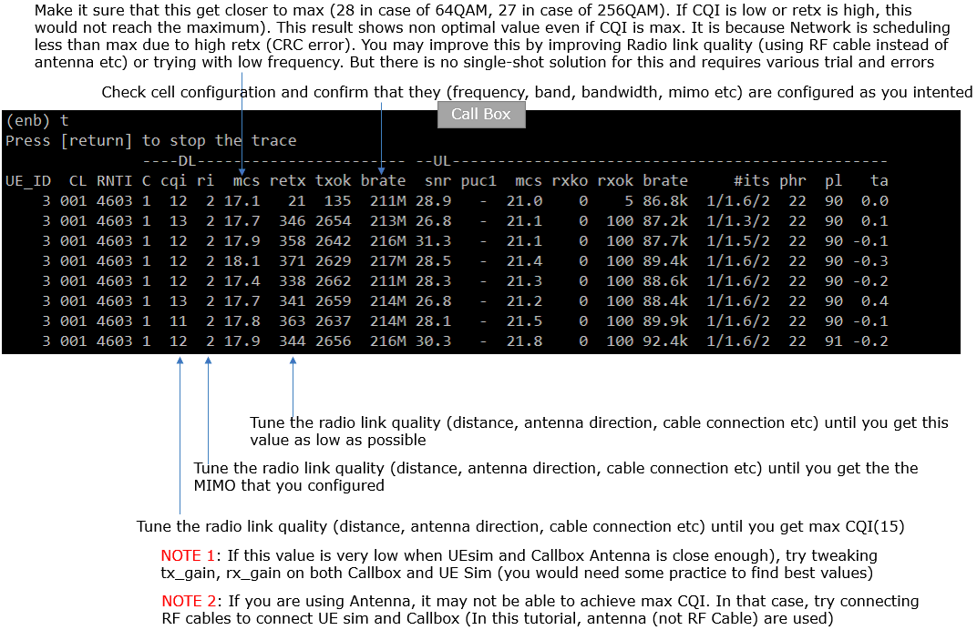
Verify the throughput
Verify the throughput with 't' command and tweak radio link condition to achieve the throughput as much as possible.
Test 2: Commercial Mobile Phone - NR SA, IPv4
This test is to show a case of iperf based on IPv4 and using a Commercial UE as DUT. In this test, I used NR SA as RAT (Radio Access Technology), but type of RAT is not important. You can use any RAT (e.g, LTE, NR NSA) in the same way as explained here.
Test Setup
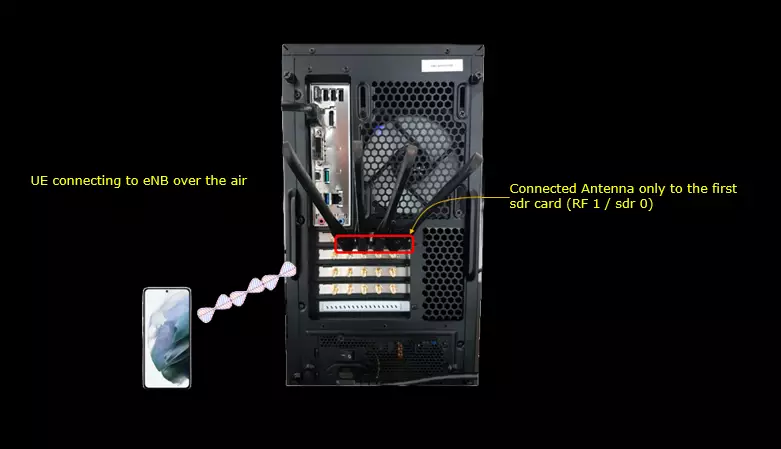
Test setup for this tutorial is as shown below.
Configuration
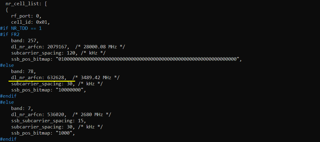
In this test, I used theconfiguration file gnb-sa-50M-sdr0.cfgthat are modified from gnb-sa.cfg as shown below.

In gnb-sa-50M-sdr0.cfg , I configured as follows. You can specify TDD/FDD(NR_TDD), MIMO(N_ANTENNA_DL) and bandwidth(NR_BANDWIDTH) etc but these details is not so imporant in this test.

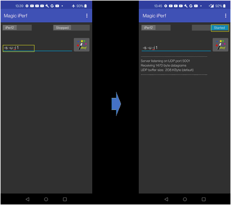
On the test UE following app was installed by default. You can install any Iperf app on your UE.

Peform the Test
Check cell configuration and confirm that they (frequency, band, bandwidth, mimo etc) are configured as you intented

Power on UE and Get UE attached to the cell and check the IP assigned to UE

Check the output of 'ue' command in (mme) and make it sure that the UE get at least one IP (IPv4 in this test) allocated.

Run iperf app on UE and run the iperf server command as shown on the left and hit [iPerf] button and you would see the status "Started" and "Server listening ..." as shown on the right.
Open up another terminal on callbox and start ping and make it sure it is going through. I recommend to keep this ping during the whole test period to prevent the Callbox to release RRC when there is no IP data. Once Callbox release RRC and gets into idle mode, iperf data may not trigger reconnection and you donít get any iperf throughput

Run the following command on Callbox to transmit the udp traffic to UE

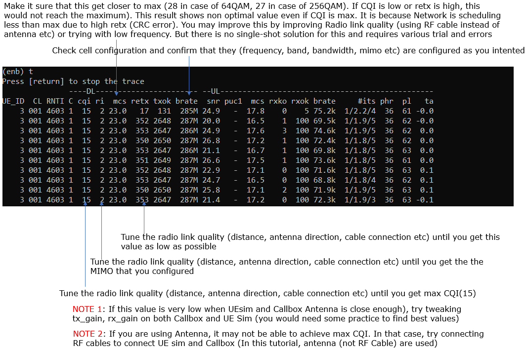
Verify the throughput
Verify the throughput with 't' command and tweak radio link condition to achieve the throughput as much as possible.
You would see the throughput logs printed on Iperf app on UE as shown below.

Test 3: UE Sim - LTE, IPv4v6
This test is to show a case of iperf based on IPv4 and using a Commercial UE as DUT. In this test, I used LTEas RAT (Radio Access Technology), but type of RAT is not important. You can use any RAT (e.g, NR NSA, NR SA) in the same way as explained here.
Test Setup

Configuration
An important thing in using UE sim is to do proper matching between UE sim configuration and Call box configuration
If you use other Network (e.g, other network simulator or real network), you have to make it sure to configure UE sim according to the settings on network side.
On UEsim, I used ue-lte-ipV4V6.cfg which is copied and modified from ue.default.cfg

On Callbox enb, I used enb.default.cfg as it is.

On Callbox mme, I used mme-ims-internet-ipv4v6.cfg which is copied and modified frommme-ims.cfg /

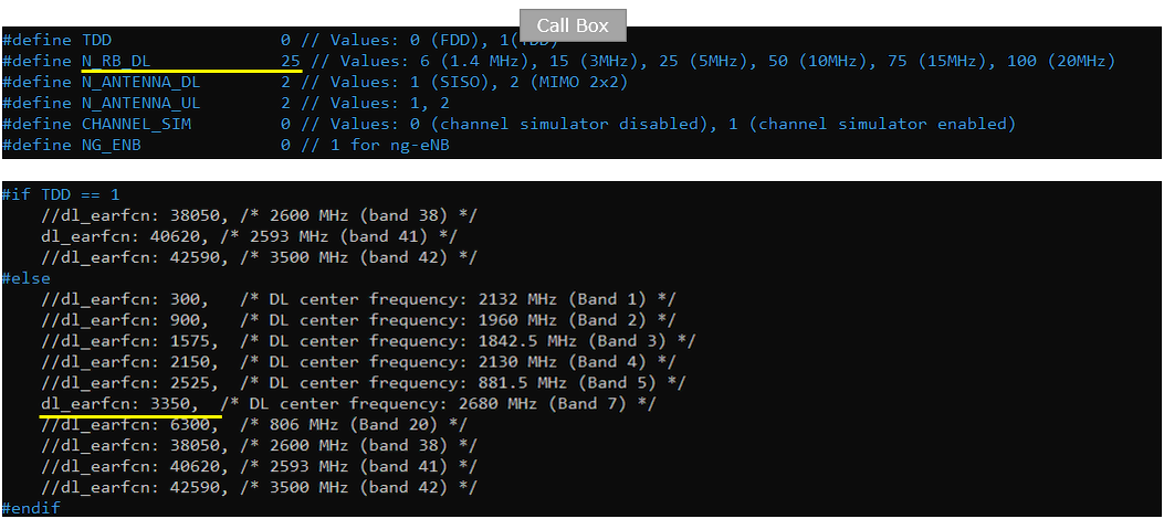
Following is the configuration enb configuration on Callbox (enb.default.cfg ). You can specify TDD/FDD(TDD), MIMO(N_ANTENNA_DL) and bandwidth(N_RB_DL) etc but these details is not so imporant in this test.
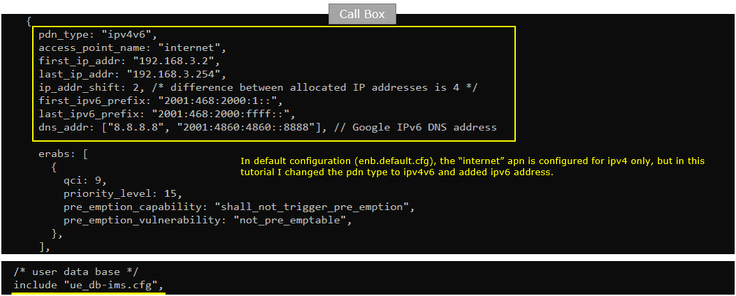
You would see following in /root/mme/config/mme-ims-internet-ipv4v6.cfg file on Callbox. Here you see both ipv4 configuration(first_ip_addr, last_ip_addr) andipv6 configuration(first_ipv6_prefix, last_ipv6_prefix) are set to support both IPv4 and IPv6.
In this tutorial, following SIM information will be used. Make it sure to configure the same parameters on UE side as well. (NOTE : this is the contents of ue_db-ims.cfg)

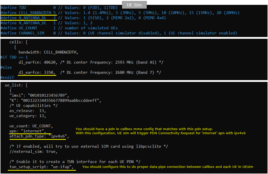
Following is the configuration on UEsim(ue-lte-ipV4V6.cfg ). You can specify TDD/FDD(TDD), MIMO(N_ANTENNA_DL) and bandwidth(CELL_BANDWIDTH) etc but these details is not so imporant in this test.
Peform the Test
Check cell configuration and confirm that they (frequency, band, bandwidth, mimo etc) are configured as you intented

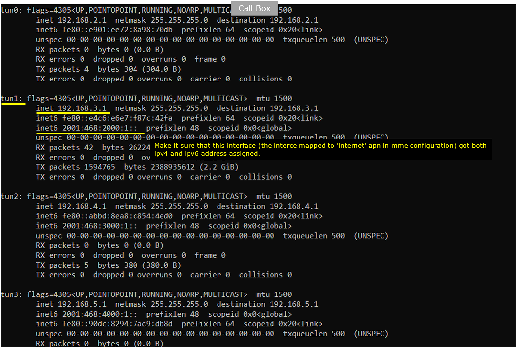
On Callbox, Do ipconfig and confirm that the IPv6 address is assigned as you configured in mme configuration.
Power on UE.

Make it sure that UE completes the attach

In Callbox mme, confirm that the UE is attached and got the IPv4 and IPv6 address allocated. (

On UEsim, confirm the ue completed the attach and get IP address allocated. (

On UEsim, confirm that you got the ue listed in the network name space.

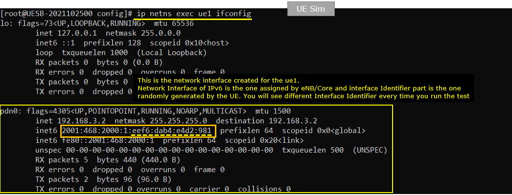
On UEsim, check ifconfig for ue1 and make it sure that it got the network interface with proper ipv6 address.
Try ping from the callbox (network) to UE.

On UEsim, run the iperf in udp server mode. -V option is to allow IPv6 address.

On Callbox, run the iperf in udp client mode and confirm that the ip iptraffic is going out.

On UEsim, confirm that IP traffic is coming in.

Test 4: UE Sim - LTE, IPv6 Only
This test is to show a case of iperf based on IPv6 and using a Commercial UE as DUT. In this test, I used LTEas RAT (Radio Access Technology), but type of RAT is not important. You can use any RAT (e.g, NR NSA, NR SA) in the same way as explained here.
Test Setup

Configuration
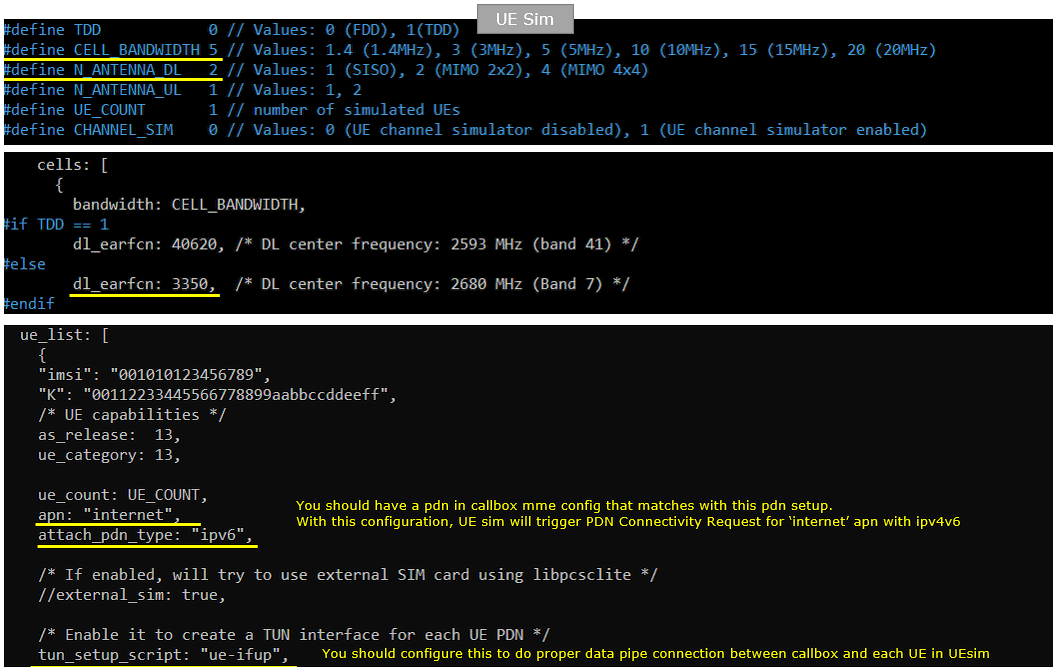
An important thing in using UE sim is to do proper matching between UE sim configuration and Call box configuration
If you use other Network (e.g, other network simulator or real network), you have to make it sure to configure UE sim according to the settings on network side.
On UEsim, I used ue-lte-ipV6.cfg which is copied and modified from ue.default.cfg

On Callbox enb, I used enb.default.cfg as it is.

On Callbox mme, I used mme-ims-internet-ipv6.cfg which is copied and modified frommme-ims.cfg /

Following is the configuration enb configuration on Callbox (enb.default.cfg ). You can specify TDD/FDD(TDD), MIMO(N_ANTENNA_DL) and bandwidth(N_RB_DL) etc but these details is not so imporant in this test.

You would see following in /root/mme/config/mme-ims-internet-ipv6.cfg file on Callbox. Here you see only ipv6 configuration(first_ipv6_prefix, last_ipv6_prefix) are set and no IPv4 configuration.
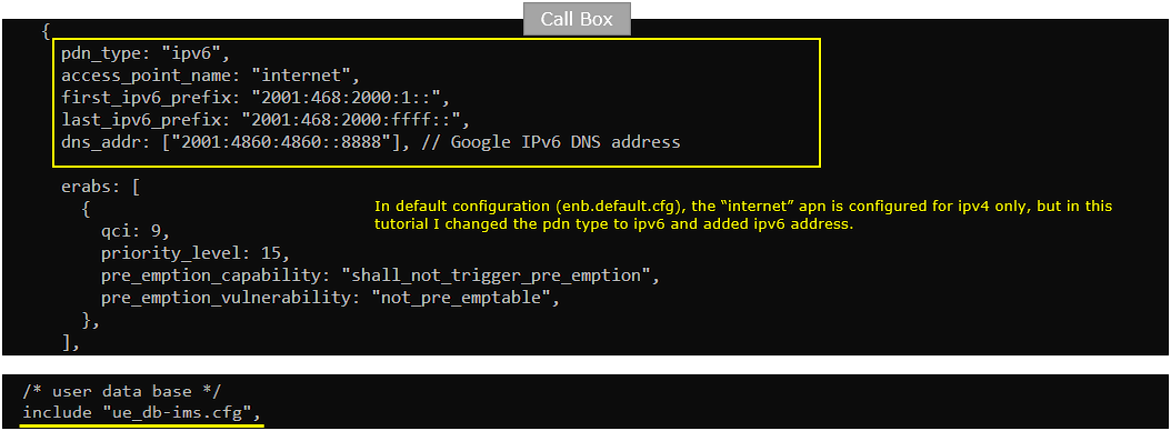
In this tutorial, following SIM information will be used. Make it sure to configure the same parameters on UE side as well. (NOTE : this is the contents of ue_db-ims.cfg)

Following is the configuration on UEsim(ue-lte-ipV6.cfg ). You can specify TDD/FDD(TDD), MIMO(N_ANTENNA_DL) and bandwidth(CELL_BANDWIDTH) etc but these details is not so imporant in this test.
Peform the Test
Check cell configuration and confirm that they (frequency, band, bandwidth, mimo etc) are configured as you intented

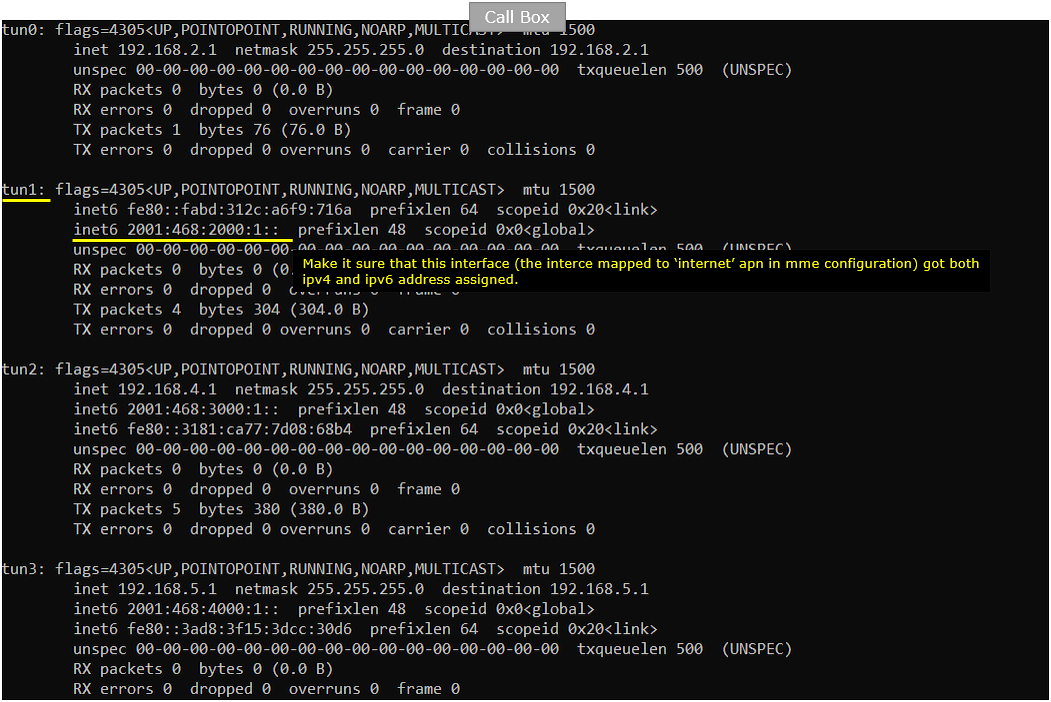
On Callbox, Do ipconfig and confirm that the IPv6 address is assigned as you configured in mme configuration.
Power on UE.

Make it sure that UE completes the attach

In Callbox mme, confirm that the UE is attached and got the IPv4 and IPv6 address allocated. (

On UEsim, confirm the ue completed the attach and get IP address allocated. (

On UEsim, confirm that you got the ue listed in the network name space.

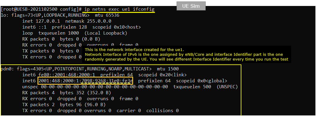
On UEsim, check ifconfig for ue1 and make it sure that it got the network interface with proper ipv6 address.
Try ping from the callbox (network) to UE.

On UEsim, run the iperf in udp server mode. -V option is to allow IPv6 address.

On Callbox, run the iperf in udp client mode and confirm that the ip iptraffic is going out.
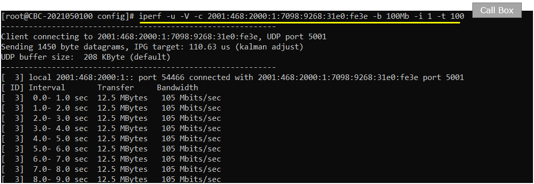
On UEsim, confirm that IP traffic is coming in.
