TDD Pattern
The purpose of this tutorial is to show you how to select a specific TDD UL/DL pattern from the predefined configuration and add your own configuration. In this tutorial, I assume that you are familiar with basic operations of callbox and I would not explain the very basic operational procedure. I will just explain about the important configurations and how you can confirm on those configuration from the log.
Main point in this tutorial is about how to configure following configuration (i.e, tdd-UL-DL-configurationCommon parameters in 3GPP). The label in black is 3GPP terminology for each configuration and the one in red is corresponding Amarisoft parameters.

image source : tdd-UL-DL-configurationCommon in sharetechnote
Table of Contents
- TDD Pattern
- Introduction
- Summary of the Tutorial
- Test Setup
- Key Configuration Parameters
- Test 1 : Single Pattern from the default configuration
- Test 2 : Dual Pattern from the default configuration
- Test 3 : Define your own configuration
- Test 4 : High UL throughput with Default CSI Configuration
- Test 5 : High UL throughput with Modified CSI Configuration
- Test 6 : Low Latency (TDD Pattern = 1.0 ms)
- Test 7 : Max DL Allocation
- Test 8 : Single Pattern with Auto CSI Configuration
- Test 9 : High UL throughput with "Auto CSI without TRS"
- Test 10 : High UL throughput with "Auto CSI with TRS"
- Test 11 : Low Latency (TDD Pattern = 0.5 ms)
- RRC / NAS Signaling
- Common Errors
- Tips
Introduction
Time Division Duplexing (TDD) in 5G NR (New Radio) networks allows dynamic allocation of uplink (UL) and downlink (DL) resources within the same frequency band, enabling highly flexible spectrum utilization and supporting diverse service requirements. The configuration of TDD UL/DL patterns—formally defined as tdd-UL-DL-configurationCommon in 3GPP specifications—dictates the scheduling and alignment of radio frames, subframes, and slots for uplink and downlink transmissions. This architectural flexibility is crucial for adapting to varying traffic demands, minimizing latency, and maximizing throughput, especially in dense urban environments and for applications with asymmetric data requirements. At the implementation level, network elements such as gNBs (next-generation NodeBs or 5G base stations) must be meticulously configured to select from predefined TDD patterns or to introduce custom configurations in compliance with both 3GPP standards and vendor-specific parameters (such as those provided by Amarisoft). Understanding the interplay between 3GPP terminology and vendor configuration interfaces is essential for network engineers and system integrators to validate, optimize, and troubleshoot TDD configurations. This tutorial focuses on the practical aspects of selecting and customizing TDD UL/DL patterns using Amarisoft’s gNB software, highlighting the mapping between standardized configuration fields and proprietary parameters, and providing guidance on confirming correct operation via system logs. The knowledge and skills imparted here are vital for professionals tasked with deploying, tuning, and maintaining 5G NR TDD systems, ensuring robust and efficient network performance within the broader telecommunications ecosystem.
-
Context and Background
- TDD in 5G NR enables flexible, dynamic allocation of uplink and downlink resources within a shared frequency, optimizing spectrum usage and supporting diverse service profiles.
- The tdd-UL-DL-configurationCommon parameter, as defined by 3GPP, governs the timing and structure of UL/DL slots and symbols across the radio interface.
- Vendors such as Amarisoft implement these parameters through proprietary configuration fields, requiring a clear understanding of the mapping between standard and vendor-specific settings.
- Precise TDD configuration is necessary for meeting network performance targets and ensuring interoperability within multi-vendor and multi-operator environments.
-
Relevance and Importance of the Tutorial
- Configuring and customizing TDD patterns is a critical task in real-world 5G NR deployments, impacting latency, throughput, and user experience.
- This tutorial addresses the practical challenges network engineers face when selecting or modifying TDD patterns using Amarisoft’s gNB platform.
- It emphasizes the importance of validating configurations through logs and system feedback to ensure correctness and optimal operation.
-
What Learners Will Gain
- A clear understanding of TDD configuration concepts in 5G NR and their significance in network architecture.
- Practical knowledge of how to select from predefined TDD patterns or introduce custom configurations using Amarisoft’s interface.
- Ability to interpret and verify TDD configuration using system logs and mapping between 3GPP and vendor-specific parameters.
- Insights into best practices for maintaining compatibility with evolving software releases and scheduler behaviors.
-
Prerequisite Knowledge and Skills
- Familiarity with basic callbox operations and general 5G NR network concepts.
- Understanding of radio frame structure, slot configuration, and 3GPP specification terminology.
- Experience with Amarisoft gNB software or equivalent base station configuration tools is recommended.
- Basic ability to read and interpret system logs for verification and troubleshooting.
Summary of the Tutorial
This tutorial demonstrates various test procedures for configuring and verifying NR TDD UL/DL patterns on a 5G gNB using Amarisoft software. Each test shows different approaches to TDD pattern selection, custom configuration, and the integration of CSI-RS (Channel State Information - Reference Signal) settings, with a focus on both throughput and latency optimization.
- Test Setup
- The test setup involves a gNB connected to a UE, with SIM card as provided. For basic SIB1 verification, UE connection is not strictly necessary.
- Configuration changes can be made via the provided guides and sample files.
- Key Configuration Parameters
- Main parameters include tdd_ul_dl_config (with pattern1/pattern2, period, dl_slots, ul_slots, dl_symbols, ul_symbols) and resource_auto for CSI-RS automation.
- Test 1: Single Pattern from Default Configuration
- Select a predefined configuration file and set NR_TDD to TDD mode (1), NR_TDD_CONFIG to 1.
- Restart the LTE service, verify no errors on startup, and collect BCCH logs to inspect SIB1 for correct pattern reflection.
- Test 2: Dual Pattern from Default Configuration
- Set NR_TDD_CONFIG to 4 for a dual-pattern cycle (pattern1: 3ms, pattern2: 2ms).
- Follow the same procedure of restarting LTE service, checking for errors, and validating SIB1 for dual pattern application.
- Test 3: Define Your Own Configuration
- Create a custom NR_TDD_CONFIG section (e.g., set to 5), define new cycle length and slot/symbol allocations.
- Restart service, ensure error-free operation, and confirm SIB1 reflects the custom pattern.
- Note that custom configs may be impacted by additional parameters (e.g., CSI), requiring careful validation and reference to the common errors section.
- Test 4: High UL Throughput with Default CSI Configuration
- Similar to Test 3, but with a focus on maximizing UL slots and symbols (e.g., 6 UL slots, 10 UL symbols in a 5ms cycle).
- Validate that the configuration is 3GPP-compliant and check SIB1 for correct application.
- Test 5: High UL Throughput with Modified CSI Configuration
- Customizes CSI-RS positions to avoid collision with UL slots, adjusting first_symb and offset for each CSI-RS instance.
- Includes detailed parameter tuning for n_ports, frequency_domain_allocation, and cdm_type.
- Verify correct SIB1 reflection and note that the configuration may behave differently with various UEs.
- Test 6: Low Latency (TDD Pattern = 1.0 ms)
- Utilizes a default low-latency configuration with a 1 ms cycle (2 slots), minimal UL/DL slots, and no TRS CSI-RS.
- Disables SRS, minimizes k_min for faster scheduling, aligns PRACH and UL symbols, and places CSI-RS to avoid SSB overlap.
- Ensures all settings are valid for low-latency and checks SIB1 for the correct pattern.
- Test 7: Max DL Allocation
- Configures maximum allowed DL resources in a 2.5 ms cycle, with minimal UL allocation.
- Uses pucch0 for simplified resource allocation and removes extra DMRS symbols for short UL slots.
- Validate by log inspection and SIB1 check.
- Test 8: Single Pattern with Auto CSI Configuration
- Enables resource_auto for automatic CSI-RS configuration matching the selected TDD pattern.
- Uses a default TDD pattern and verifies that the software automatically configures compatible CSI-RS resources.
- Test 9: High UL Throughput with "Auto CSI without TRS"
- Demonstrates disabling TRS transmission (trs_presence: false) when auto CSI configuration leads to TRS setup errors due to insufficient DL slots.
- Validates the pattern in SIB1 and ensures error-free operation.
- Test 10: High UL Throughput with "Auto CSI with TRS"
- Shows how to enable TRS even in slots used for SSB and SIB1 by setting exclude_slot_ssb and exclude_slot_sib1 to false.
- Ensures two consecutive slots for TRS in FR1 are available and validates the configuration by checking SIB1.
- Test 11: Low Latency (TDD Pattern = 0.5 ms)
- Uses a 0.5 ms cycle (partial slots for DL and UL), disables SRS, minimizes k_min, and aligns PRACH for low-latency operations.
- Carefully positions CSI-RS to avoid SSB overlap and configures PUSCH to use all available UL symbols.
- Checks SIB1 for proper pattern application and validates with different UEs.
General Methodology Across Tests:
- Select or modify a configuration file appropriate for the test objective.
- Set NR_TDD to TDD mode and select the appropriate NR_TDD_CONFIG index.
- Restart LTE services, monitor for errors, and adjust configurations as necessary to resolve issues.
- Collect logs (typically via BCCH) and inspect SIB1 to verify that the TDD pattern and relevant parameters are reflected as intended.
- When using custom or advanced configurations, ensure that CSI-RS and other signaling resources do not conflict with the chosen TDD pattern.
- Refer to the Common Errors section for troubleshooting, especially regarding CSI-RS and UL slot collisions. Adjust CSI-RS positions or disable TRS as needed.
- For low latency or maximum throughput, follow specific guidelines (e.g., packing DL/UL symbols, careful PRACH and PUSCH allocation, minimizing k_min).
Additional Tips
- For low latency, reduce TDD periodicity and optimize PRACH and PUSCH allocation according to available UL symbols.
- When using special slots, configure pusch.partial_slots to enable PUSCH scheduling in those slots.
- Always validate new configurations for 3GPP compliance and operational stability.
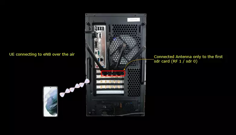
Test Setup
Test setup for this tutorial is as shown below. (
- SIM Card used in this tutorial is the one delivered with the system as it is.
- If you want to change the configuration, The tutorial Configuration Guide would help
Key Configuration Parameters
Followings are important configuration parameters for this tutorial. You may click on the items for the descriptions from Amarisoft documents.
- tdd_ul_dl_config : In this link, you can get the descriptions for all the parameters listed below
- ref_subcarrier_spacing
- pattern1
- period
- dl_slots
- ul_slots
- dl_symbols
- ul_symbols
- pattern2
- period
- dl_slots
- ul_slots
- dl_symbols
- ul_symbols
- resource_auto : In this link, you can get the descriptions for all the parameters listed below
- trs_presence
- exclude_slot_ssb
- exclude_slot_sib1
Test 1 : Single Pattern from the default configuration
This is an example of a very simple and standard TDD pattern that is made up of single pattern. Around 70% allocated for downlink and around 20% allocated for uplink and a little bit less than 10% is configured for flexible slots (special slots).
Configuration
I used the configuration gnb-sa-tdd-pattern.cfg which is copied from gnb-sa.cfg and modified for this tutorial.
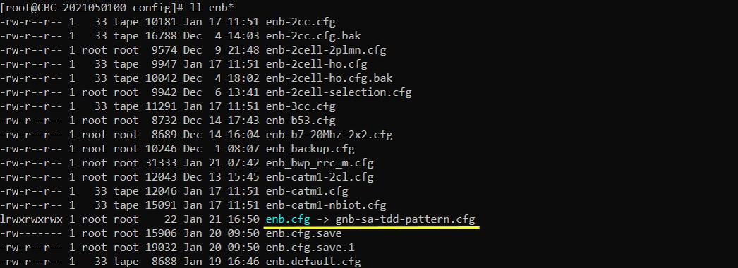
In the configuration file, you can select any specific tdd pattern with the parameter NR_TDD_CONFIG. To apply TDD configuration, you first need to configure the duplex mode (NR_TDD) to 1 (TDD). And then I set NR_TDD_CONFIG to 1 which is one of default sample configuration provided by Amarisoft sample configuration.

For example, if you select TDD_CONFIG == 1 as in this test, the pattern as shown below is applied. In this configuration, the cycle length is 5ms which is 10 slots in case of Subcarrier spacing 30Khz. Out of the 10 slots, 7 slots and 2 OFDM symbols are allocated for downlink by the parameter dl_slots and dl_symbols respectively. 2 slots and 2 OFDM symbols are allocated for uplink by the parameter ul_slots and ul_symbols respectively.

Run and Check
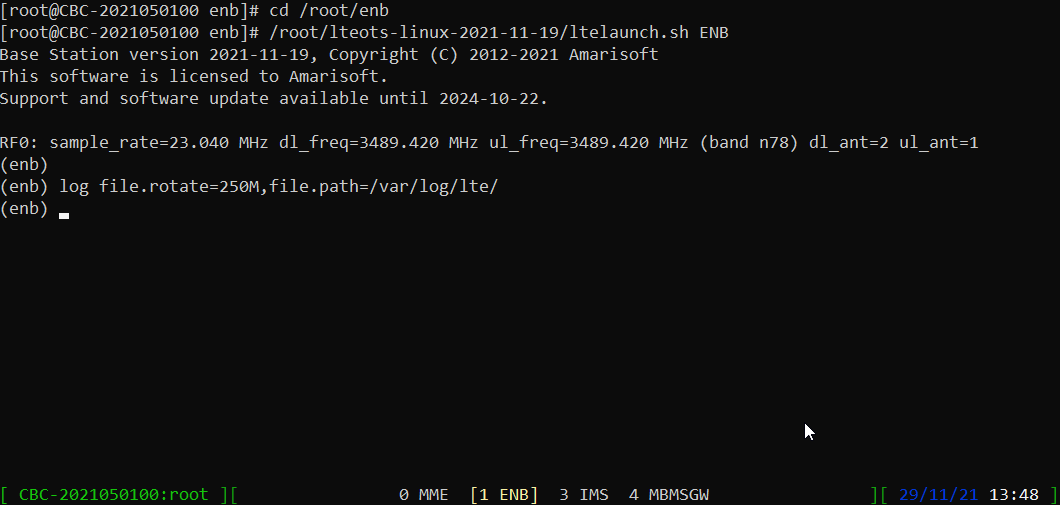
Restart the lte service and launch the screen. Switch to (enb) and make it sure that you don't get any error message. If you use the configuration predefined in the configuration file, you may not get any error since they are already tested but if you modify it or define a new configuration, you may see some errors described in Common Errors section.
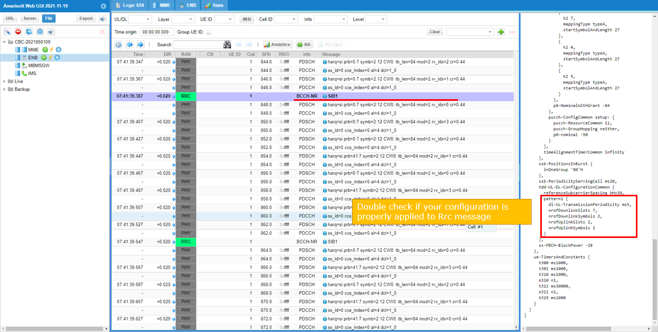
Collect the log with bcch and check the contents of SIB1.
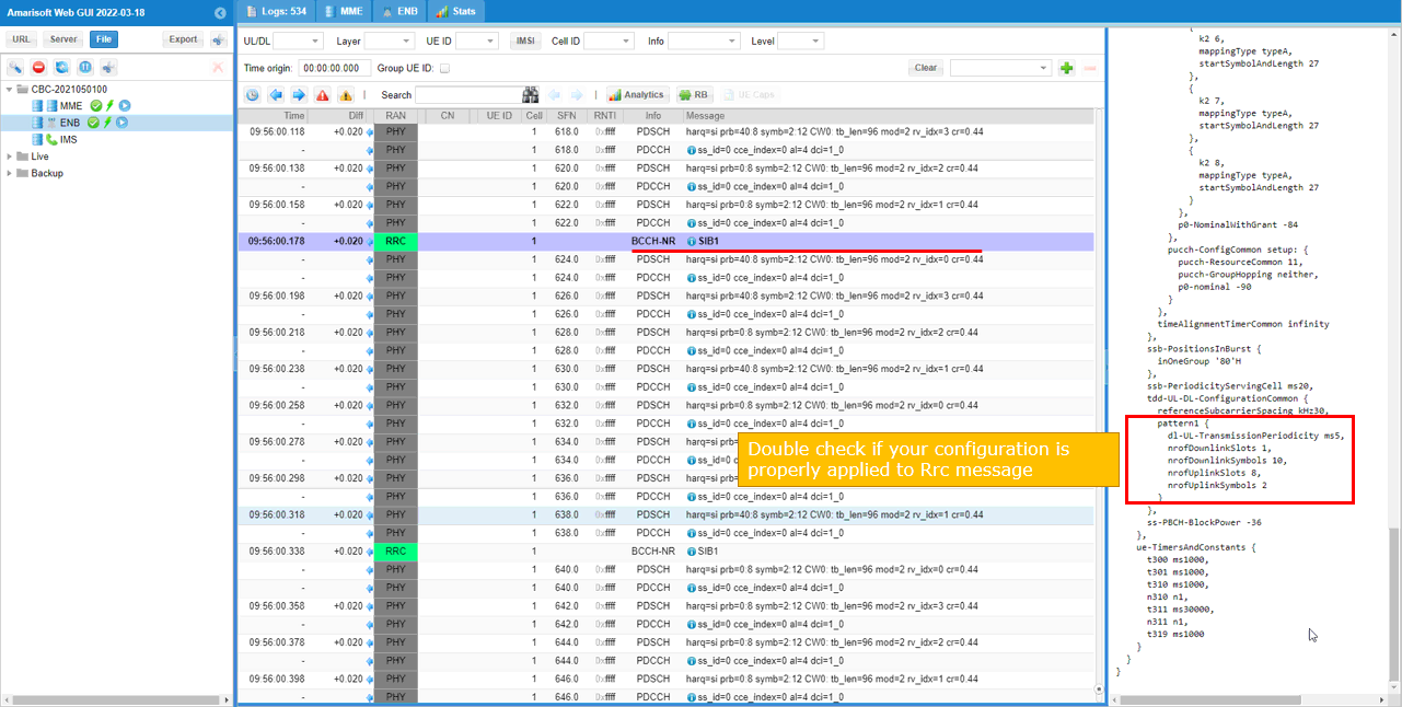
See if your configuration is properly relected into SIB1 as shown below. You see tdd-UL-DL-ConfigurationCommon carries pattern1 only (meaning single pattern). dl-UL-TransmissionPeriodicity corresponds to the parameter period, nrofDownlinkSlots corresponds to dl_slots. nrofDownlinksymbols corresponds to dl_symbols. nrofUplinkSlots and nrofUplinkSymbols corresponds to ul_slots and ul_symbols respectively.
Test 2 : Dual Pattern from the default configuration
This is a little bit complicated configuration than the case of previous test. It is made up of two patterns. The first pattern takes up 60 % of the overall cycle and the second pattern takes up 40% of the overall cycle.
Configuration
I used the configuration gnb-sa-tdd-pattern.cfg which is copied from gnb-sa.cfg and modified for this tutorial.

In the configuration file, you can select any specific tdd pattern with the parameter NR_TDD_CONFIG. To apply TDD configuration, you first need to configure the duplex mode (NR_TDD) to 1 (TDD). And then I set NR_TDD_CONFIG to 4 which is one of default sample configuration provided by Amarisoft sample configuration.

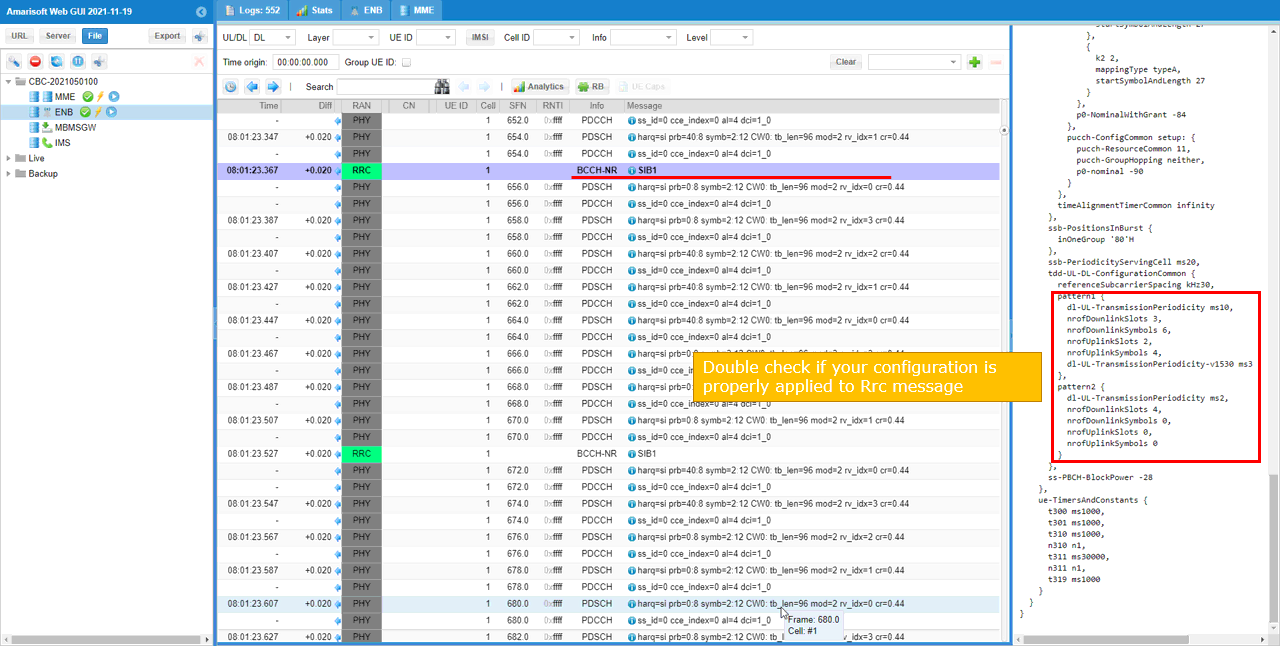
For example, if you select TDD_CONFIG == 4 as in this test, the pattern as shown below is applied. In this configuration, the cycle length is 5ms which is 10 slots in case of Subcarrier spacing 30Khz. Out of the 5 ms(10 slots), pattern1 takes up 3ms(6 slots) and pattern2 takes up 2ms(4 slots). For pattern 1, 3 slots and 6 OFDM symbols are allocated for downlink by the parameter dl_slots and dl_symbols respectively. 2 slots and 4 OFDM symbols are allocated for uplink by the parameter ul_slots and ul_symbols respectively. For pattern 2, 4 slots symbols are allocated for downlink by the parameter dl_slots and dl_symbols respectively. No slots and symbols are allocated for uplink by the parameter ul_slots and ul_symbols respectively.

Run and Check
Restart the lte service and launch the screen. Switch to (enb) and make it sure that you don't get any error message. If you use the configuration predefined in the configuration file, you may not get any error since they are already tested but if you modify it or define a new configuration, you may see some errors described in Common Errors section.

Collect the log with bcch and check the contents of SIB1. See if your configuration is properly relected into SIB1 as shown below.
See if your configuration is properly relected into SIB1 as shown below. You see tdd-UL-DL-ConfigurationCommon carries pattern1 and pattern 2 (meaning dual pattern). dl-UL-TransmissionPeriodicity corresponds to the parameter period, nrofDownlinkSlots corresponds to dl_slots. nrofDownlinksymbols corresponds to dl_symbols. nrofUplinkSlots and nrofUplinkSymbols corresponds to ul_slots and ul_symbols respectively.
Test 3 : Define your own configuration
This test is just to show you how to define your own TDD DL/UL ConfigCommon. There are roughly two different ways to do it.
i) Just change values of the configuration that are defined in the basic config file (e.g, gnb-sa.cfg)
ii) Create you own �#elif NR_TDD_CONFIG == X� section
I am using the method ii) in this section
Configuration
I used the configuration gnb-sa-tdd-pattern.cfg which is copied from gnb-sa.cfg and modified for this tutorial.

In the configuration file, you can select any specific tdd pattern with the parameter NR_TDD_CONFIG. In the configuration file, you can select any specific tdd pattern with the parameter NR_TDD_CONFIG. To apply TDD configuration, you first need to configure the duplex mode (NR_TDD) to 1 (TDD). And then I set NR_TDD_CONFIG to 5 which is not in the list of default sample configuration provided by Amarisoft sample configuration.
(

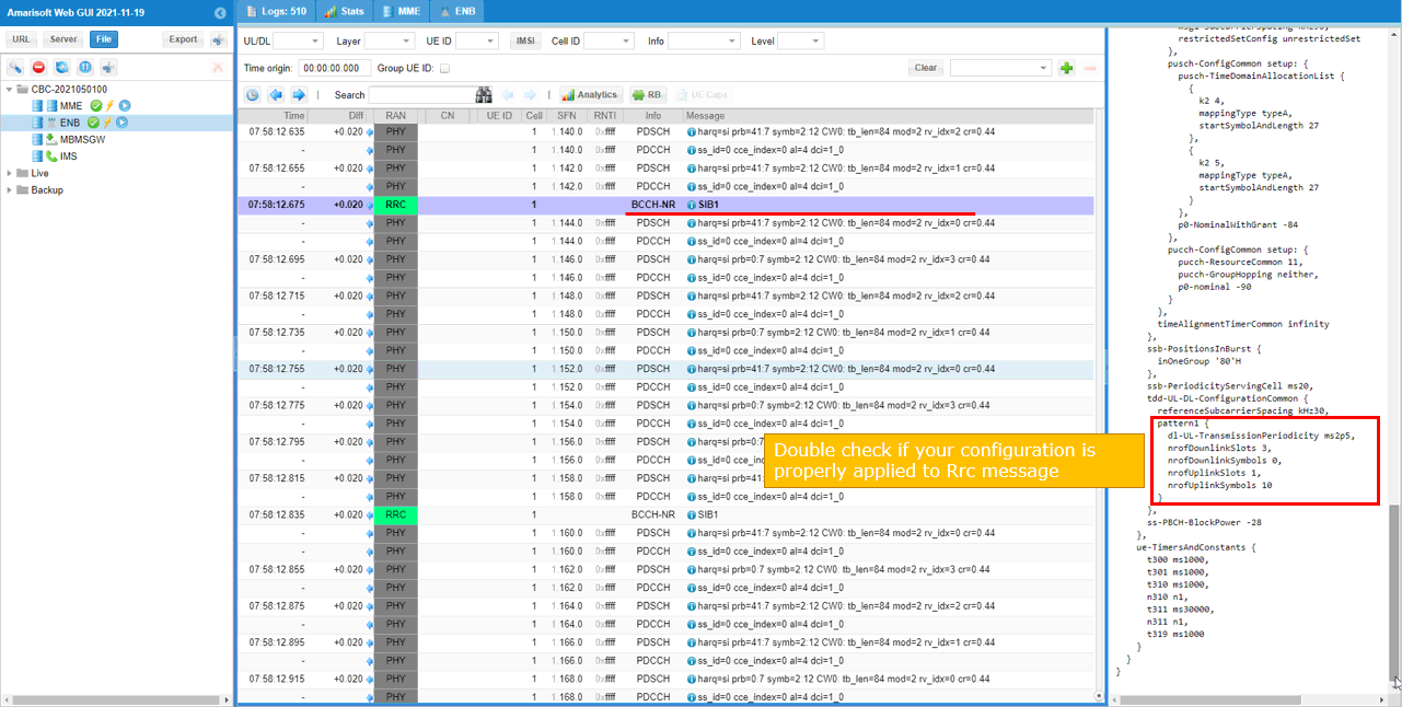
Define your own configuration as follows (this is not the one in the default configuration). In this configuration, the cycle length is 2.5ms which is 5 slots in case of Subcarrier spacing 30Khz. Out of the 5 slots, 3 slots are allocated for downlink by the parameter dl_slots and dl_symbols respectively. 1 slots and 10 OFDM symbols are allocated for uplink by the parameter ul_slots and ul_symbols respectively.

Refer to [Common Errors] section for some possible errors you may see when you configure this parametes on your own.
Run and Check
Restart the lte service and launch the screen. Switch to (enb) and make it sure that you don't get any error message. If you use the configuration predefined in the configuration file, you may not get any error since they are already tested but if you modify it or define a new configuration, you may see some errors described in Common Errors section.

Collect the log with bcch and check the contents of SIB1. See if your configuration is properly relected into SIB1 as shown below.
See if your configuration is properly relected into SIB1 as shown below. You see tdd-UL-DL-ConfigurationCommon carries pattern1 only (meaning single pattern). dl-UL-TransmissionPeriodicity corresponds to the parameter period, nrofDownlinkSlots corresponds to dl_slots. nrofDownlinksymbols corresponds to dl_symbols. nrofUplinkSlots and nrofUplinkSymbols corresponds to ul_slots and ul_symbols respectively.
Test 4 : High UL throughput with Default CSI Configuration
This test is just to show you how to define your own TDD DL/UL ConfigCommon. There are roughly two different ways to do it.
i) Just change values of the configuration that are defined in the basic config file (e.g, gnb-sa.cfg)
ii) Create you own �#elif NR_TDD_CONFIG == X� section
I am using the method ii) in this section
Configuration
I used the configuration gnb-sa-ul-highTp-defCSI.cfg which is copied from gnb-sa.cfg and modified for this tutorial.

In the configuration file, you can select any specific tdd pattern with the parameter NR_TDD_CONFIG. In the configuration file, you can select any specific tdd pattern with the parameter NR_TDD_CONFIG. In the configuration file, you can select any specific tdd pattern with the parameter NR_TDD_CONFIG. To apply TDD configuration, you first need to configure the duplex mode (NR_TDD) to 1 (TDD). And then I set NR_TDD_CONFIG to 5 which is not in the list of default sample configuration provided by Amarisoft sample configuration.
(

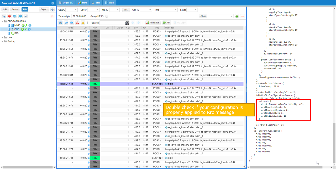
Define your own configuration as follows (this is not the one in the default configuration). In this configuration, the cycle length is 5ms which is 10 slots in case of Subcarrier spacing 30Khz. Out of the 10 slots, 3 slots and 2 OFDM symbols are allocated for downlink by the parameter dl_slots and dl_symbols respectively. 6 slots and 10 OFDM symbols are allocated for uplink by the parameter ul_slots and ul_symbols respectively.

Refer to [Common Errors] section for some possible errors you may see when you configure this parametes on your own.
Run and Check
Restart the lte service and launch the screen. Switch to (enb) and make it sure that you don't get any error message. If you use the configuration predefined in the configuration file, you may not get any error since they are already tested but if you modify it or define a new configuration, you may see some errors described in Common Errors section.

Collect the log with bcch and check the contents of SIB1. See if your configuration is properly relected into SIB1 as shown below. (NOTE : I have tried this configuration with a commercial UE (OnePLUS 8T) and it successfully attached to gNB and Internet Speedtest was running OK.
See if your configuration is properly relected into SIB1 as shown below. You see tdd-UL-DL-ConfigurationCommon carries pattern1 only (meaning single pattern). dl-UL-TransmissionPeriodicity corresponds to the parameter period, nrofDownlinkSlots corresponds to dl_slots. nrofDownlinksymbols corresponds to dl_symbols. nrofUplinkSlots and nrofUplinkSymbols corresponds to ul_slots and ul_symbols respectively.
Test 5 : High UL throughput with Modified CSI Configuration
This test is just to show you how to define your own TDD DL/UL ConfigCommon. There are roughly two different ways to do it.
i) Just change values of the configuration that are defined in the basic config file (e.g, gnb-sa.cfg)
ii) Create you own �#elif NR_TDD_CONFIG == X� section
I am using the method ii) in this section
Configuration
I used the configuration gnb-sa-ul-highTp-modCSI.cfg which is copied from gnb-sa.cfg and modified for this tutorial.

In the configuration file, you can select any specific tdd pattern with the parameter NR_TDD_CONFIG. In the configuration file, you can select any specific tdd pattern with the parameter NR_TDD_CONFIG. In the configuration file, you can select any specific tdd pattern with the parameter NR_TDD_CONFIG. To apply TDD configuration, you first need to configure the duplex mode (NR_TDD) to 1 (TDD). And then I set NR_TDD_CONFIG to 5 which is not in the list of default sample configuration provided by Amarisoft sample configuration.
(

Define your own configuration as follows (this is not the one in the default configuration). In this configuration, the cycle length is 5ms which is 10 slots in case of Subcarrier spacing 30Khz. Out of the 10 slots, 1 slots and 10 OFDM symbols are allocated for downlink by the parameter dl_slots and dl_symbols respectively. 8 slots and 2 OFDM symbols are allocated for uplink by the parameter ul_slots and ul_symbols respectively.
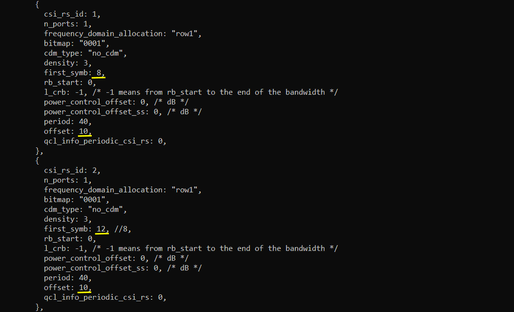
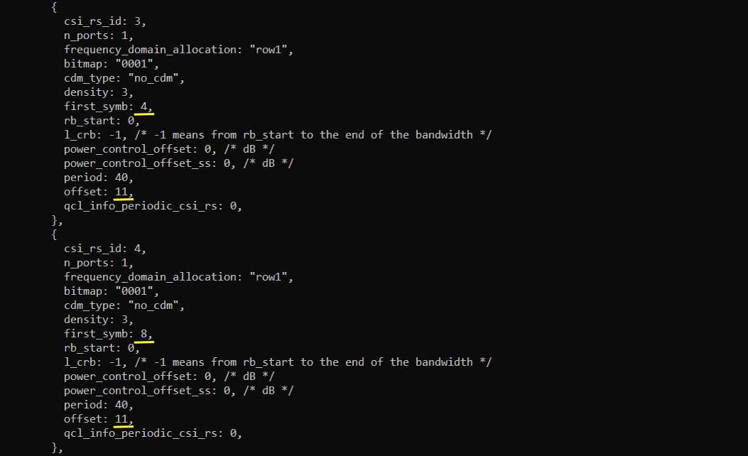
I configured as many as slots for UL that does not require CSI-RS configuration in the default sample scenario gnb-sa.cfg. In gnb-sa.cfg, slot 0 is reserved for DL to transmit SSB and CSI-RS are configured to be transmitted in slot 1 and 2 which requires 3DL slots in total. So in the configuration for this test, I will change CSI-RS configuration in such a way that they are transmitted with the first 20 symbols without overlapping with SSB.

Refer to [Common Errors] section for some possible errors you may see when you configure this parametes on your own.
I changed slot and symbol position of CSI-RS so that they are all positioned with 20 symbols.
The parameters to be noted in this example are as follows : (NOTE : the detailed meaning of each of these parameter in terms of 3GPP, check out this note)
- frequency_domain_allocation, cdm_type : the configuration for csi_rs_id 0 is for CSI report and csi_rs_id 1,2,3,4 is to configure TRS.
- n_ports : this is set to be same as the number of DL Antenna for CSI report and set to 1 for TRS
- first_symb, offset : set these in such a way that does not overlap each other and set to meet TRS requirement if they are for TRS.



Run and Check
Restart the lte service and launch the screen. Switch to (enb) and make it sure that you don't get any error message. If you use the configuration predefined in the configuration file, you may not get any error since they are already tested but if you modify it or define a new configuration, you may see some errors described in Common Errors section.

Collect the log with bcch and check the contents of SIB1. See if your configuration is properly relected into SIB1 as shown below. (
See if your configuration is properly relected into SIB1 as shown below. You see tdd-UL-DL-ConfigurationCommon carries pattern1 only (meaning single pattern). dl-UL-TransmissionPeriodicity corresponds to the parameter period, nrofDownlinkSlots corresponds to dl_slots. nrofDownlinksymbols corresponds to dl_symbols. nrofUplinkSlots and nrofUplinkSymbols corresponds to ul_slots and ul_symbols respectively.
Test 6 : Low Latency (TDD Pattern = 1.0 ms)
This is not a new configuration. It is default configuration in the installation package. I am just trying to show you the logics behind this low latency configuration. It would help you with applying the logic to create your own configuration when you need.
Some important points to pay attention to this configuration are as follows.
- Very short TDD pattern period : only two slots of period (1 ms, 1 subframe)
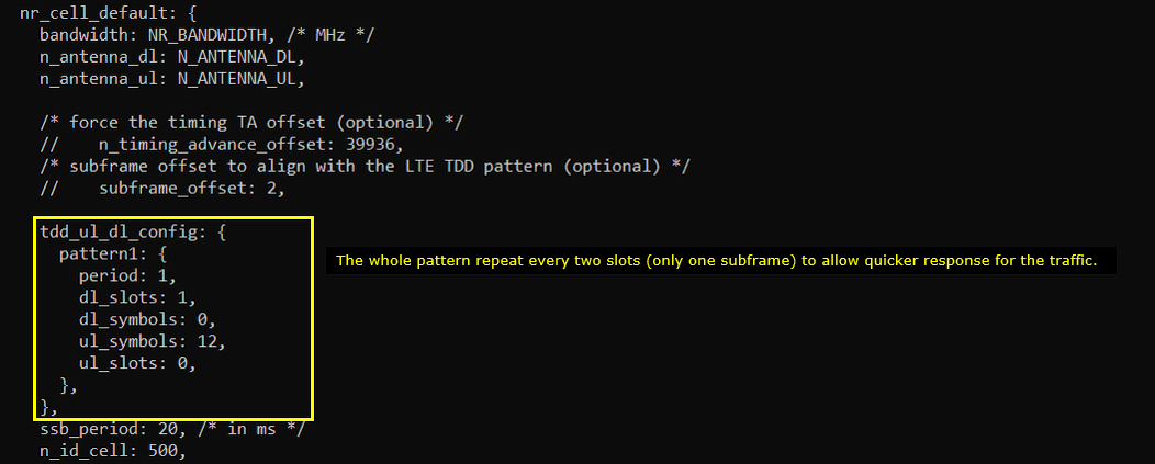
- 1 full slot for DL and 12 symbols for UL
- Removing CSI RS for TRS. (For FR1 TRS, we need at least two consecutive slots to configure TRS.. but we have only 1 slot for DL which cannot accommodate the TRS).
- CSI RS for CSI Report is positioned in slot 0 which is same slot as SSB. You need to position CSI-RS carefully so as NOT to overlap SSB symbols).
- Disable SRS. You may enable it if you really need it, but in that case you would need to decrease the number of symbols to PUSCH (lowering UL throughput) to reserve space for SRS.
- Reduce the value for k_min to reduce k1 and k2 min.
Configuration
I used the configuration gnb-sa-tdd-low-latency.cfg which is included in the installation package. (

In the configuration file, disable SRS.

Since the whole perioid is only 1 ms which is 2 slots in case of 30Khz SCS and 1 full slot is allocated for downlink, Uplink is max 1 slot. But in order to allow some gap between downlink to uplink, I set less than 1 slot is assigned for UL.
Reduce sr_period. This is to let UE not wait too long to get UL grant. If UL grant gets delayed, overall latency would get longer.

PRACH Configuration is chosen in such a way that RO(RACH Occassion) is only on UL symbols. (

Reduce k_min value. This setting reduce the min value for k1 and k2 so that gNB can get UE response more quickly and grant ul more quicaly. This would required high CPU performance and you'd better check 't cpu' and real time condition maintains on your setup.

Put CSI RS for CSI Report at the first slot (slotoffset = 0) of each periods. SSB bitmap is '10000000' which occupies the symbol [2,3,4,5]. So the CSI RS is placed at symbol 6 so that it does not overlap SSB symbols. (
The parameters to be noted in this example are as follows : (NOTE : the detailed meaning of each of these parameter in terms of 3GPP, check out this note)
- frequency_domain_allocation, cdm_type : the configuration for csi_rs_id 0 is for CSI report and csi_rs_id 1,2,3,4 is to configure TRS.
- n_ports : this is set to be same as the number of DL Antenna for CSI report and set to 1 for TRS
- first_symb, offset : set these in such a way that does not overlap each other and set to meet TRS requirement if they are for TRS.
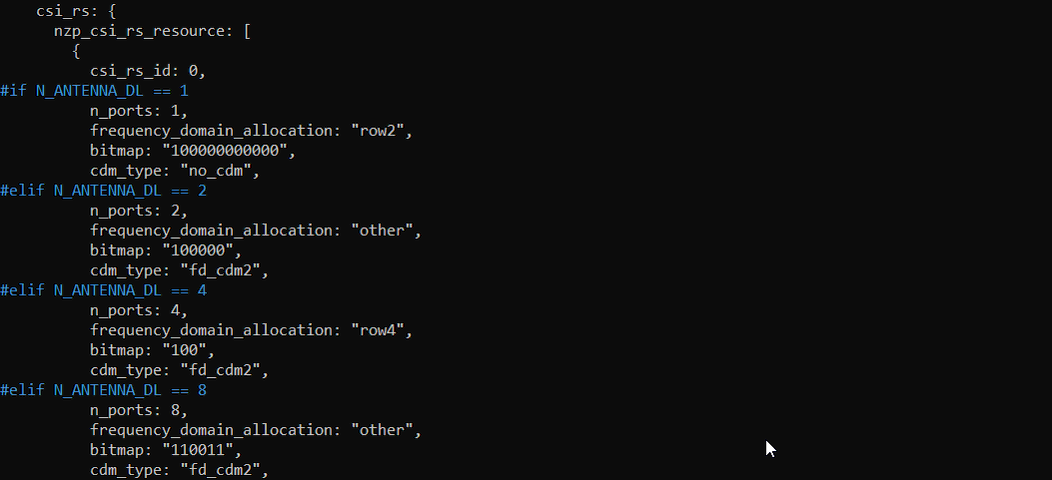
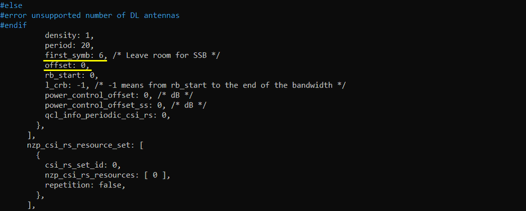
In the same logic, place the csi_im_resource and zp_csi_rs_resource at the slot 0 (slotoffset 0) of the period and the symbol should not overap with SSB symbol and nzp_csi_rs_resource.
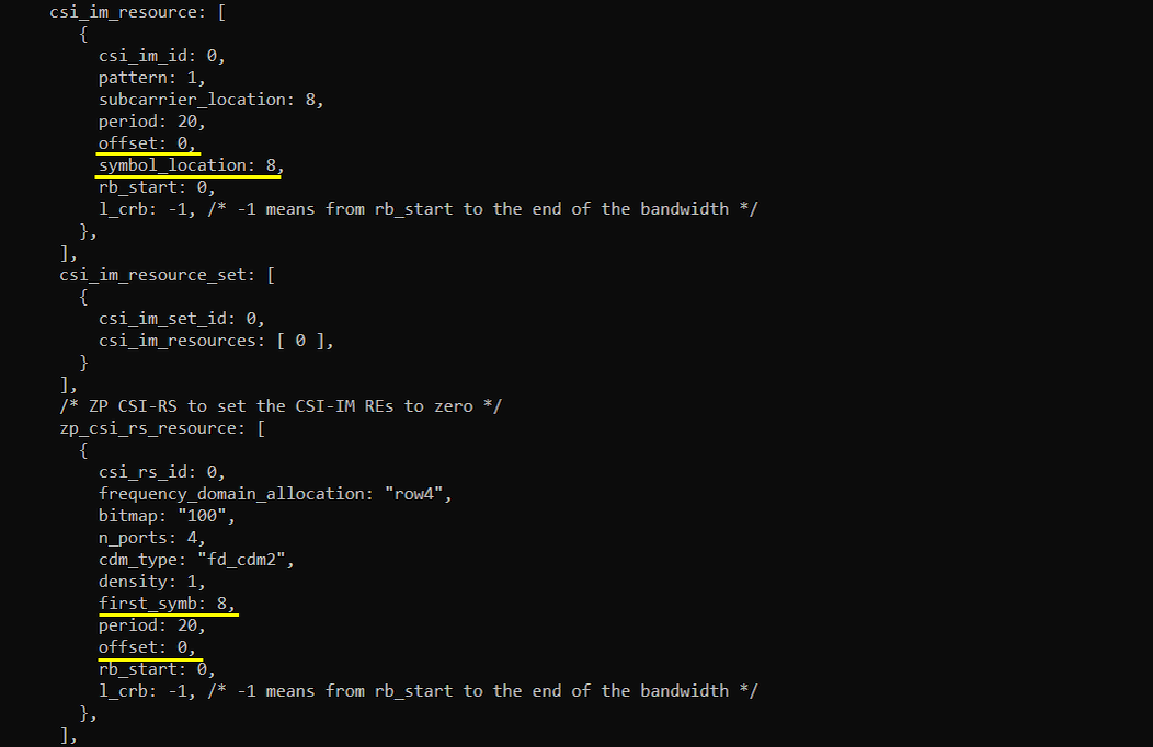
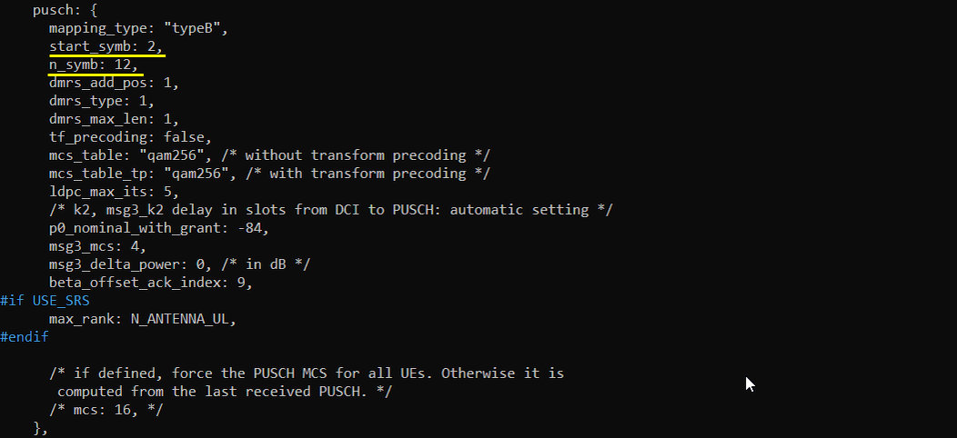
Allocate PUSCH to fill up all the symbols assigned in TDD pattern. If you reduce the number of UL symbols in TDD pattern or enable SRS, you need to change start_symb and n_symb accordinly.
Run and Check
Restart the lte service and launch the screen. Switch to (enb) and make it sure that you don't get any error message. If you use the configuration predefined in the configuration file, you may not get any error since they are already tested but if you modify it or define a new configuration, you may see some errors described in Common Errors section.

Collect the log with bcch and check the contents of SIB1. See if your configuration is properly relected into SIB1 as shown below. (
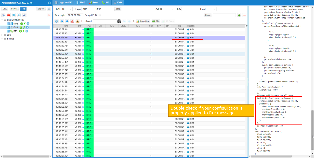
See if your configuration is properly relected into SIB1 as shown below. You see tdd-UL-DL-ConfigurationCommon carries pattern1 only (meaning single pattern). dl-UL-TransmissionPeriodicity corresponds to the parameter period, nrofDownlinkSlots corresponds to dl_slots. nrofDownlinksymbols corresponds to dl_symbols. nrofUplinkSlots and nrofUplinkSymbols corresponds to ul_slots and ul_symbols respectively.
Test 7 : Max DL Allocation
This test is just to show you how to allocate time domain resources for DL as much as possible.
Configuration
I used the configuration gnb-sa-tdd-pattern-maxDL.cfg which is copied from gnb-sa.cfg and modified for this tutorial.

In the configuration file, you can select any specific tdd pattern with the parameter NR_TDD_CONFIG. In the configuration file, you can select any specific tdd pattern with the parameter NR_TDD_CONFIG. In the configuration file, you can select any specific tdd pattern with the parameter NR_TDD_CONFIG. To apply TDD configuration, you first need to configure the duplex mode (NR_TDD) to 1 (TDD). And then I set NR_TDD_CONFIG to 5 which is not in the list of default sample configuration provided by Amarisoft sample configuration.
(

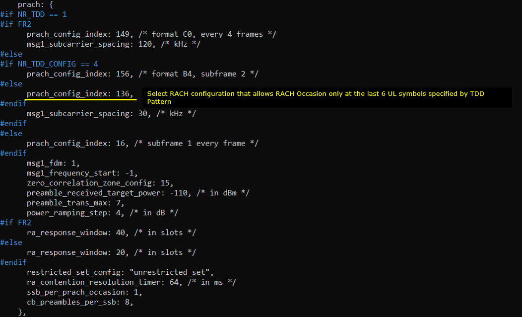
Define your own configuration as follows (this is not the one in the default configuration). In this configuration, the cycle length is 2.5ms which is 5 slots in case of Subcarrier spacing 30Khz. Out of the 5 slots, 4 slots and 6 OFDM symbols are allocated for downlink by the parameter dl_slots and dl_symbols respectively. Only 6 OFDM symbols are allocated for uplink by the parameter ul_slots and ul_symbols respectively.

Refer to [Common Errors] section for some possible errors you may see when you configure this parametes on your own.
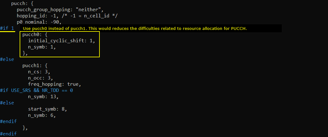
Use pucch0 instead of pucch1 because it would reduce the difficulties associated with resource allocation for PUCCH.
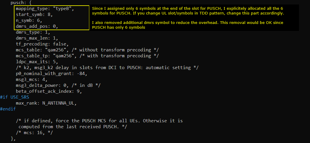
Since I assigned only 6 symbols at the end of the slot for PUSCH, I explicitely allocated all the 6 symbols for PUSCH. If you change UL slot/symbols in TDD pattern, change this part accordingly. I also removed the additional dmrs symbols to reduce the overhead. This removal would be OK since PUSCH is not so long (only 6 symbols). (
Run and Check
Restart the lte service and launch the screen. Switch to (enb) and make it sure that you don't get any error message. If you use the configuration predefined in the configuration file, you may not get any error since they are already tested but if you modify it or define a new configuration, you may see some errors described in Common Errors section.

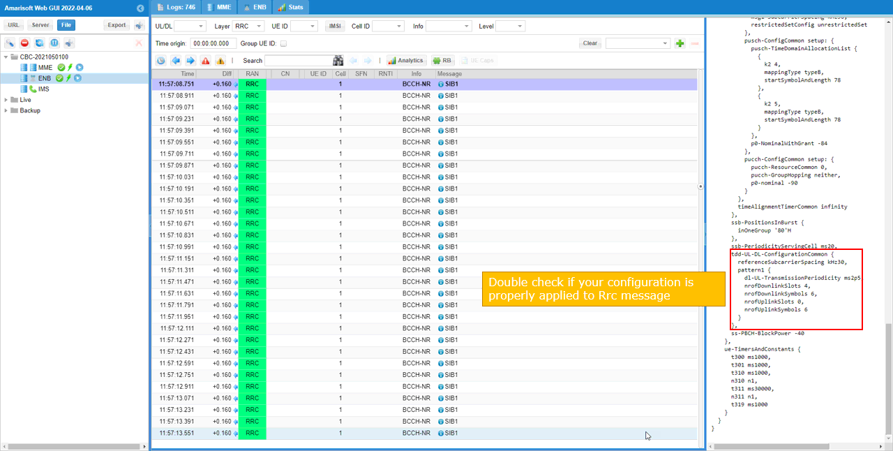
Collect the log with bcch and check the contents of SIB1. See if your configuration is properly relected into SIB1 as shown below. (
See if your configuration is properly relected into SIB1 as shown below. You see tdd-UL-DL-ConfigurationCommon carries pattern1 only (meaning single pattern). dl-UL-TransmissionPeriodicity corresponds to the parameter period, nrofDownlinkSlots corresponds to dl_slots. nrofDownlinksymbols corresponds to dl_symbols. nrofUplinkSlots and nrofUplinkSymbols corresponds to ul_slots and ul_symbols respectively.
Test 8 : Single Pattern with Auto CSI Configuration
From 2022-06-17, Auto CSI configuration is supported to simplify the CSI configuration. With this feature, you may just change tdd pattern without modifying CSI configuration manually. gNB software configures CSI automatically to be compatible with the tdd configuration you configured. (For further details of Auto CSI configuration itself, please refer to Reference Configuration : Auto CSI Configuration )
Configuration
I used the configuration gnb-sa-autoCSI.cfg which is copied from gnb-sa.cfg and modified for this tutorial.

In the configuration file, you can select any specific tdd pattern with the parameter NR_TDD_CONFIG. In the configuration file, you can select any specific tdd pattern with the parameter NR_TDD_CONFIG. In the configuration file, you can select any specific tdd pattern with the parameter NR_TDD_CONFIG. To apply TDD configuration, you first need to configure the duplex mode (NR_TDD) to 1 (TDD). And then I set NR_TDD_CONFIG to 2 which is one of default sample configuration provided by Amarisoft sample configuration.
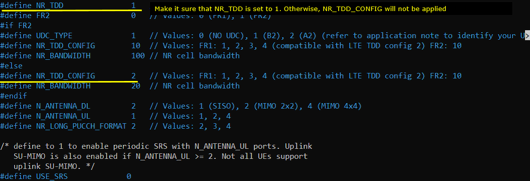
For example, if you select TDD_CONFIG == 2 as in this test, the pattern as shown below is applied. In this configuration, the cycle length is 5ms which is 10 slots in case of Subcarrier spacing 30Khz. Out of the 10 slots, 7 slots and 6 OFDM symbols are allocated for downlink by the parameter dl_slots and dl_symbols respectively. 2 slots and 4 OFDM symbols are allocated for uplink by the parameter ul_slots and ul_symbols respectively.

In auto CSI configuration, the whole csi-rs configuration is as simple as shown below. All the remaining details are configured automatically by gNB software.

Run and Check
Restart the lte service and launch the screen. Switch to (enb) and make it sure that you don't get any error message. If you use the configuration predefined in the configuration file, you may not get any error since they are already tested but if you modify it or define a new configuration, you may see some errors described in Common Errors section.

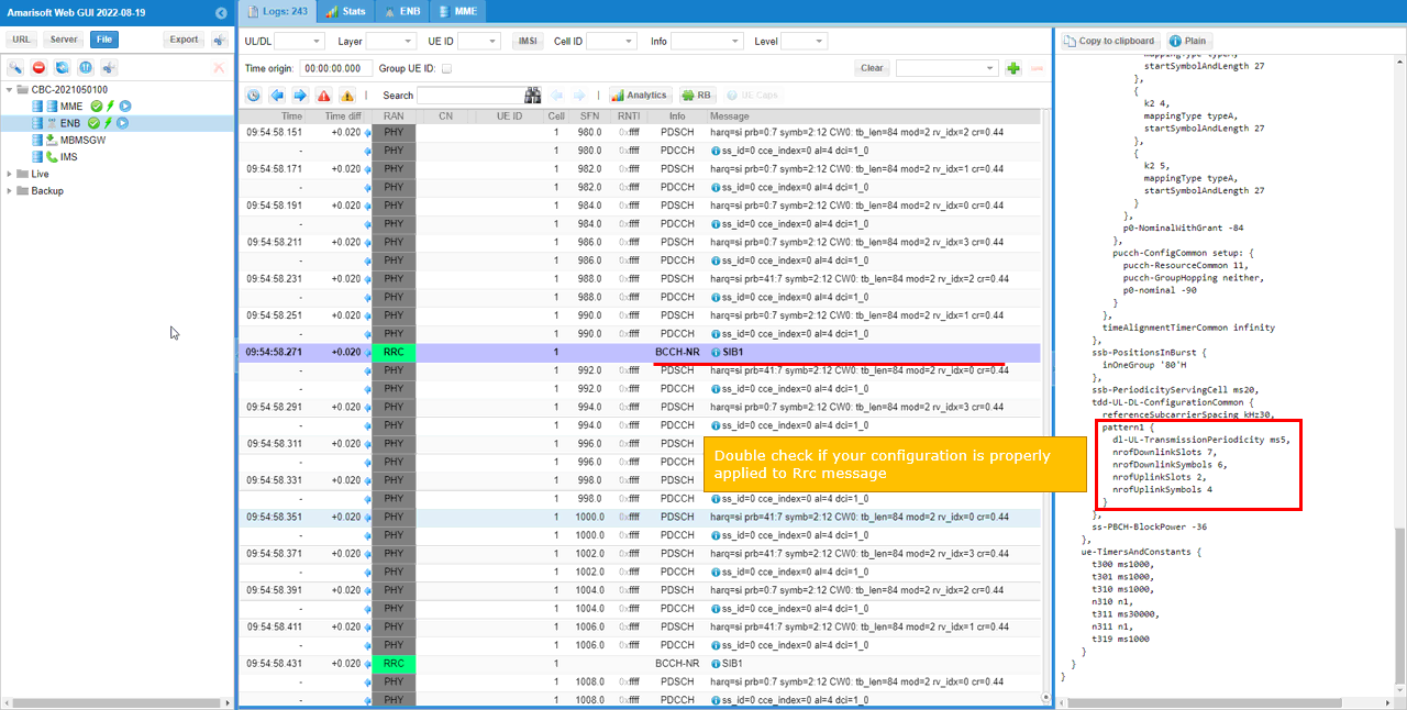
Collect the log with bcch and check the contents of SIB1. See if your configuration is properly relected into SIB1 as shown below.
See if your configuration is properly relected into SIB1 as shown below. You see tdd-UL-DL-ConfigurationCommon carries pattern1 only (meaning single pattern). dl-UL-TransmissionPeriodicity corresponds to the parameter period, nrofDownlinkSlots corresponds to dl_slots. nrofDownlinksymbols corresponds to dl_symbols. nrofUplinkSlots and nrofUplinkSymbols corresponds to ul_slots and ul_symbols respectively.
Test 9 : High UL throughput with "Auto CSI without TRS"
From 2022-06-17, Auto CSI configuration is supported to simplify the CSI configuration. With this feature, you may just change tdd pattern without modifying CSI configuration manually. gNB software configures CSI automatically to be compatible with the tdd configuration you configured. (For further details of Auto CSI configuration itself, please refer to Reference Configuration : Auto CSI Configuration )
In many of the typical TDD pattern, the default auto csi configuration would properly configure the CSI RS, but sometimes you may need to add some additional configurations to avoid any possible limitation (for example, in case when the number of DL slots is not enough to configure the necessary TRS).
This test is an example where you need to add some additional configuration to the default auto csi configuration. If you apply the tdd pattern in this example with the default auto csi configuration, you would get an error about TRS configuration setup. To remove the error, I disabled TRS transmission.
Configuration
I used the configuration gnb-sa-ul-highTp-autoCSI-noTRS.cfg which is copied from gnb-sa.cfg and modified for this tutorial.

In the configuration file, you can select any specific tdd pattern with the parameter NR_TDD_CONFIG. In the configuration file, you can select any specific tdd pattern with the parameter NR_TDD_CONFIG. In the configuration file, you can select any specific tdd pattern with the parameter NR_TDD_CONFIG. To apply TDD configuration, you first need to configure the duplex mode (NR_TDD) to 1 (TDD). And then I set NR_TDD_CONFIG to 5 which is not in the list of default sample configuration provided by Amarisoft sample configuration.
(
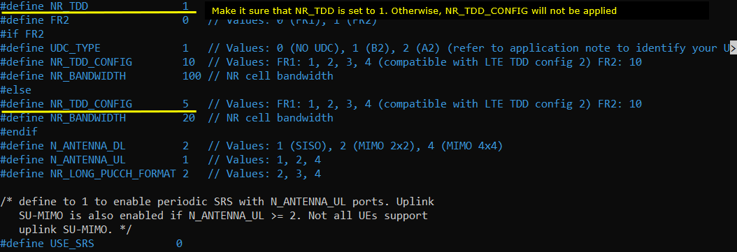
For example, if you select TDD_CONFIG == 5 as in this test, the pattern as shown below is applied. In this configuration, the cycle length is 5ms which is 10 slots in case of Subcarrier spacing 30Khz. Out of the 10 slots, 1 slots and 10 OFDM symbols are allocated for downlink by the parameter dl_slots and dl_symbols respectively. 8 slots and 2 OFDM symbols are allocated for uplink by the parameter ul_slots and ul_symbols respectively.

In this test, I set trs_presence: false which disables trs transmission (i.e, gNB does not configure CSI-RS for TRS) as shown below.

Run and Check
Restart the lte service and launch the screen. Switch to (enb) and make it sure that you don't get any error message. If you use the configuration predefined in the configuration file, you may not get any error since they are already tested but if you modify it or define a new configuration, you may see some errors described in Common Errors section.

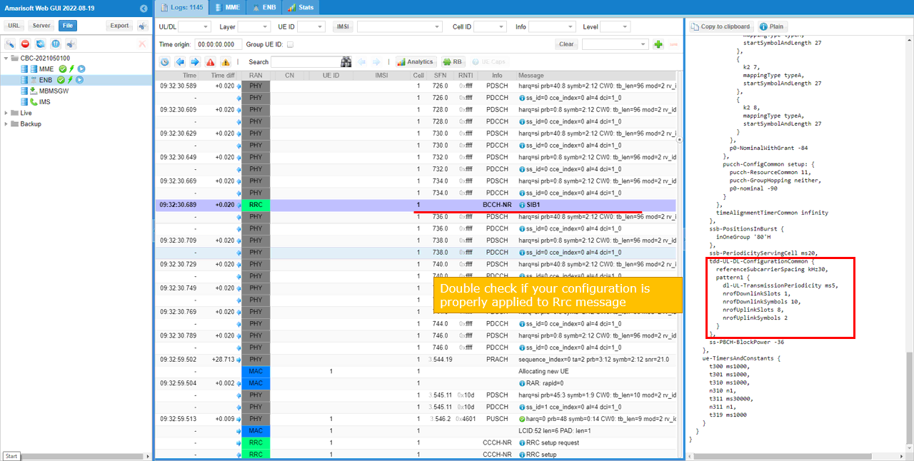
Collect the log with bcch and check the contents of SIB1. See if your configuration is properly relected into SIB1 as shown below.
See if your configuration is properly relected into SIB1 as shown below. You see tdd-UL-DL-ConfigurationCommon carries pattern1 only (meaning single pattern). dl-UL-TransmissionPeriodicity corresponds to the parameter period, nrofDownlinkSlots corresponds to dl_slots. nrofDownlinksymbols corresponds to dl_symbols. nrofUplinkSlots and nrofUplinkSymbols corresponds to ul_slots and ul_symbols respectively.
Test 10 : High UL throughput with "Auto CSI with TRS"
From 2022-06-17, Auto CSI configuration is supported to simplify the CSI configuration. With this feature, you may just change tdd pattern without modifying CSI configuration manually. gNB software configures CSI automatically to be compatible with the tdd configuration you configured. (For further details of Auto CSI configuration itself, please refer to Reference Configuration : Auto CSI Configuration )
In many of the typical TDD pattern, the default auto csi configuration would properly configure the CSI RS, but sometimes you may need to add some additional configurations to avoid any possible limitation (for example, in case when the number of DL slots is not enough to configure the necessary TRS).
This test is an example where you need to add some additional configuration to the default auto csi configuration. If you apply the tdd pattern in this example with the default auto csi configuration, you would get an error about TRS configuration setup. To remove the error, I added the additional configurations.
Configuration
I used the configuration gnb-sa-ul-highTp-autoCSI-TRSonSSB.cfg which is copied from gnb-sa.cfg and modified for this tutorial.

In the configuration file, you can select any specific tdd pattern with the parameter NR_TDD_CONFIG. In the configuration file, you can select any specific tdd pattern with the parameter NR_TDD_CONFIG. In the configuration file, you can select any specific tdd pattern with the parameter NR_TDD_CONFIG. To apply TDD configuration, you first need to configure the duplex mode (NR_TDD) to 1 (TDD). And then I set NR_TDD_CONFIG to 5 which is not in the list of default sample configuration provided by Amarisoft sample configuration.
(

For example, if you select TDD_CONFIG == 5 as in this test, the pattern as shown below is applied. In this configuration, the cycle length is 5ms which is 10 slots in case of Subcarrier spacing 30Khz. Out of the 10 slots, 1 slots and 10 OFDM symbols are allocated for downlink by the parameter dl_slots and dl_symbols respectively. 8 slots and 2 OFDM symbols are allocated for uplink by the parameter ul_slots and ul_symbols respectively.

In this test, I set the following two parameters which enable trs transmission even on ssb and sib1 slots to secure the two consecutive slots which is required for TRS transmission in FR1.

Run and Check
Restart the lte service and launch the screen. Switch to (enb) and make it sure that you don't get any error message. If you use the configuration predefined in the configuration file, you may not get any error since they are already tested but if you modify it or define a new configuration, you may see some errors described in Common Errors section.

Collect the log with bcch and check the contents of SIB1. See if your configuration is properly relected into SIB1 as shown below.
See if your configuration is properly relected into SIB1 as shown below. You see tdd-UL-DL-ConfigurationCommon carries pattern1 only (meaning single pattern). dl-UL-TransmissionPeriodicity corresponds to the parameter period, nrofDownlinkSlots corresponds to dl_slots. nrofDownlinksymbols corresponds to dl_symbols. nrofUplinkSlots and nrofUplinkSymbols corresponds to ul_slots and ul_symbols respectively.

Test 11 : Low Latency (TDD Pattern = 0.5 ms)
This is not a new configuration. It is default configuration in the installation package. I am just trying to show you the logics behind this low latency configuration. It would help you with applying the logic to create your own configuration when you need.
Some important points to pay attention to this configuration are as follows.
- Very short TDD pattern period : only two slots of period (0.5 ms, half subframe/one slot)
- partial slot for DL and partial slot for UL
- Removing CSI RS for TRS. (For FR1 TRS, we need at least two consecutive slots to configure TRS.. but we have only 1 slot for DL which cannot accommodate the TRS).
- CSI RS for CSI Report is positioned in slot 0 which is same slot as SSB. You need to position CSI-RS carefully so as NOT to overlap SSB symbols).
- Disable SRS. You may enable it if you really need it, but in that case you would need to decrease the number of symbols to PUSCH (lowering UL throughput) to reserve space for SRS.
- Reduce the value for k_min to reduce k1 and k2 min.
Configuration
I used the configuration gnb-sa-tdd-low-latency_0_5.cfg which is copied and modified from gnb-sa-tdd-low-latency.cfg

In the configuration file, disable SRS.

Since the whole perioid is only 1 ms which is 2 slots in case of 30Khz SCS and a partial slot(9 symbols) is allocated for downlink, Uplink is also partial slot which is 4 symbols in this case.
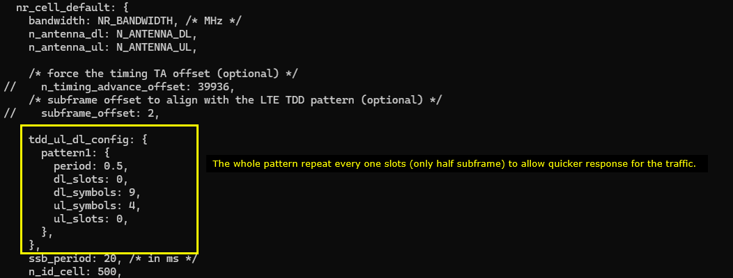
Reduce sr_period. This is to let UE not wait too long to get UL grant. If UL grant gets delayed, overall latency would get longer.

PRACH Configuration is chosen in such a way that RO(RACH Occassion) is only on UL symbols. (

Reduce k_min value. This setting reduce the min value for k1 and k2 so that gNB can get UE response more quickly and grant ul more quicaly. This would required high CPU performance and you'd better check 't cpu' and real time condition maintains on your setup.

Put CSI RS for CSI Report at the first slot (slotoffset = 0) of each periods. SSB bitmap is '10000000' which occupies the symbol [2,3,4,5]. So the CSI RS is placed at symbol 6 so that it does not overlap SSB symbols. (
The parameters to be noted in this example are as follows : (NOTE : the detailed meaning of each of these parameter in terms of 3GPP, check out this note)
- frequency_domain_allocation, cdm_type : the configuration for csi_rs_id 0 is for CSI report and csi_rs_id 1,2,3,4 is to configure TRS.
- n_ports : this is set to be same as the number of DL Antenna for CSI report and set to 1 for TRS
- first_symb, offset : set these in such a way that does not overlap each other and set to meet TRS requirement if they are for TRS.

In the same logic, place the csi_im_resource and zp_csi_rs_resource at the slot 0 (slotoffset 0) of the period and the symbol should not overap with SSB symbol and nzp_csi_rs_resource.

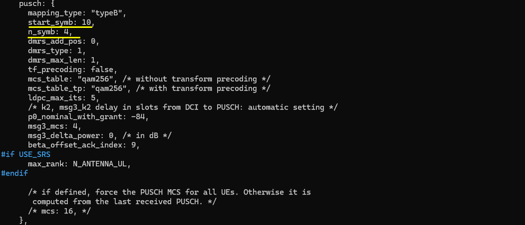
Allocate PUSCH to fill up all the symbols assigned in TDD pattern. If you reduce the number of UL symbols in TDD pattern or enable SRS, you need to change start_symb and n_symb accordinly.

Run and Check
Restart the lte service and launch the screen. Switch to (enb) and make it sure that you don't get any error message. If you use the configuration predefined in the configuration file, you may not get any error since they are already tested but if you modify it or define a new configuration, you may see some errors described in Common Errors section.

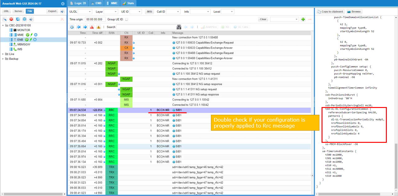
Collect the log with bcch and check the contents of SIB1. See if your configuration is properly relected into SIB1 as shown below. (
See if your configuration is properly relected into SIB1 as shown below. You see tdd-UL-DL-ConfigurationCommon carries pattern1 only (meaning single pattern). dl-UL-TransmissionPeriodicity corresponds to the parameter period, nrofDownlinkSlots corresponds to dl_slots. nrofDownlinksymbols corresponds to dl_symbols. nrofUplinkSlots and nrofUplinkSymbols corresponds to ul_slots and ul_symbols respectively.
RRC / NAS Signaling
SIB1 (SA)
: This is the SIB1 message sent by gNB to configure NR SA. (
{
message c1: systemInformationBlockType1: {
...
servingCellConfigCommon {
...
tdd-UL-DL-ConfigurationCommon {
referenceSubcarrierSpacing kHz30,
pattern1 {
dl-UL-TransmissionPeriodicity ms5,
nrofDownlinkSlots 7,
nrofDownlinkSymbols 6,
nrofUplinkSlots 2,
nrofUplinkSymbols 4
}
},
}
Common Errors
Case 1 : Collision between Uplink CSI-RS and NZP CSI-RS
This would be one of the most common error you may get when you try to apply your own configuration. NZP CSI-RS is a type of downlink reference signal. It cannot be transmitted in uplink slot. It mean your TDD UL/DL Config assigns some UL slot which is same as the slot where CSI-RS is transmitted.

You can fix this problem in a few different ways.
Method 1 : The simplest way would be to comment out following lines. With this, CSI-RS configuration would be omitted. So it would not collide with any UL slot in your configuration. This is the recommended way for most of the cases
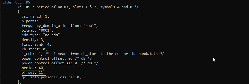
Method 2 : If you want to transmit TRS CSI-RS with your own configuration, change following parameter for all the csi_rs configuration in such a way that those reference signal is transmitted via DL slots in your configuration
Tips
Guide line for Low Latency
We configure Low Latency mainly adjusting TDD UL/DL Configuration Common (TDD Pattern) to achieve the low latency (
- Reduce the periodicity and pack the DL/UL symbols with the periodicity (Ex, this test). This is relatively easy since you can easily visualize the configuration.
- Select appropriate PRACH configuration. In most of Low Latency TDD pattern, we usually schedule partial UL slots (i.e, no full slot UL, only a few symbols at the end of a slot). So you need to ensure to choose a proper PRACH configuration that falls into the short UL region. This is tricky because it is not easy to figure out (or visualize) the RO(RACH Occassion) symbols for each PRACH configuration. Refer to this note for the details.
- When there is no full slot UL, you need to configure carefully about pusch SLIV (i.e, mapping type B, start symbol, number of symbols) to ensure the scheduled PUSCH fall into UL region of TDD Pattern. This is not that difficult because you can easily visualize this configuration.
PUSCH Scheduling in special slot
In default configuration, PUSCH is not scheduled in special slot (i.e, the slot in which both DL and UL symbols are configured). The symbols in this slot is reserved for special uplink signal like SRS.
If you want to schedule PUSCH even for those special slots, you need to configure the parameter : partial_slots