
Cell Reference Power
This tutorial shows how Amari Callbox specify Cell Reference Power for each radio technology (NR SA, LTE, NB IoT) and how you can verify it. CellReferencePower indicates the power of reference signal that is transmitted by eNB/gNB. UE compares this value broadcasted by SIB and the reference power it measures, and estimate the downlink pathloss based on the result. Regardless of radio access technology, all radio technology broadcast this information (reference power) in one of SIBs. The IE (information element) name for each of the radio technology is as follows :
- NR : ss-PBCH-BlockPower
- LTE : referenceSignalPower
- NB IoT : nrs-Power-r13
Table of Contents
- Cell Reference Power
- Introduction
- Summary of the Tutorial
- Test Setup
- Configuration
- NR SA Cell Reference Power
- LTE Cell Reference Power
- NB IoT Cell Reference Power
- Broadcast Reference Power Variation Among Software Release
- Release 2021-11-17 : NR SA Reference Power in SIB1
- Release 2022-04-01 : NR SA Reference Power in SIB1
- Broadcast Reference Power Variation with Channel Bandwidth
- Tips
Introduction
Cell Reference Power is a fundamental parameter within cellular radio access technologies such as NR Standalone (NR SA), LTE, and NB-IoT, playing a critical role in the assessment of downlink signal strength and pathloss estimation in wireless networks. In the context of the Amari Callbox platform, specifying and verifying Cell Reference Power is essential for accurate emulation and measurement of radio environments. The Cell Reference Power, broadcasted in various System Information Blocks (SIBs), represents the power level of the reference signal transmitted by the base station (eNB/gNB). User Equipment (UE) receives this information and compares it with the measured reference signal strength, enabling precise calculation of downlink pathloss. Each radio technology employs a specific information element (IE) within the SIBs: ss-PBCH-BlockPower for NR, referenceSignalPower for LTE, and nrs-Power-r13 for NB-IoT. Amari Callbox, by default, determines and sets these values automatically based on SDR hardware capabilities, operating frequency, and other configuration parameters. However, advanced users can manually override these values for specialized testing scenarios. Understanding the configuration and verification of Cell Reference Power is vital for network engineers, researchers, and testers working with modern cellular technologies, as it directly impacts the accuracy of link budget calculations and performance evaluation in laboratory and field environments.
-
Context and Background
- Cell Reference Power is a key metric for downlink pathloss estimation, used by UE to optimize connectivity and handover decisions.
- All major radio access technologies—NR SA, LTE, and NB-IoT—broadcast reference power information in SIBs using technology-specific IEs.
- Amari Callbox is a versatile platform for cellular protocol testing, supporting automated and manual configuration of reference power for precise network emulation.
-
Relevance and Importance
- Correct configuration and verification of Cell Reference Power ensures accurate emulation of real-world radio conditions during testing.
- Directly influences link budget analysis, which is fundamental to coverage estimation, capacity planning, and performance assessment.
- Empowers users to replicate specific network scenarios or comply with standardization requirements in research and development.
-
Tutorial Outcomes
- Understand how to specify Cell Reference Power for each supported radio technology (NR SA, LTE, NB-IoT) in Amari Callbox.
- Learn the process for verifying the configured reference power using Amari Callbox measurement tools and logs.
- Gain insights into the impact of reference power settings on UE measurements and network simulation fidelity.
- Acquire practical knowledge for both automated (default) and manual (hardcoded) configuration workflows.
-
Prerequisite Knowledge and Skills
- Basic understanding of cellular network architecture and radio access technologies (NR, LTE, NB-IoT).
- Familiarity with Amari Callbox system environment and general configuration procedures.
- Knowledge of SDR hardware (SDR50, SDR100) and its impact on radio signal parameters.
- Ability to interpret System Information Blocks (SIBs) and relevant information elements (IEs) as per 3GPP specifications.
Summary of the Tutorial
This tutorial describes procedures to test and analyze the broadcast reference power settings in various radio access technologies (RATs), focusing on the information transmitted in System Information Blocks (SIBs). The procedures cover NR SA (Standalone New Radio), LTE, and NB IoT cell reference power, as well as variations caused by software releases and channel bandwidth. The following summarizes the test methodologies:
-
NR SA Cell Reference Power Test:
- Restart the LTE service and access the screen window to obtain basic physical layer information about the cell.
- Enable logging for SIB messages.
- Check the ss-PBCH-BlockPower parameter.
- Conduct experiments to determine the correlation between the call box transmission power and the ss-PBCH-BlockPower set by the call box.
-
LTE Cell Reference Power Test:
- Restart the LTE service and access the screen window to obtain basic physical layer information about the cell.
- Enable logging for SIB messages.
- Check the referenceSignalPower parameter.
- Conduct experiments to determine the correlation between the call box transmission power and the referenceSignalPower set by the call box.
-
NB IoT Cell Reference Power Test:
- Restart the LTE service and access the screen window to obtain basic physical layer information about the cell.
- Enable logging for SIB messages.
- Check the nrs-Power parameter.
- Conduct experiments to determine the correlation between the call box transmission power and the nrs-Power set by the call box.
-
Broadcast Reference Power Variation Among Software Releases:
- Compare the reference power values broadcast in SIB messages across different software releases to identify any changes, which may occur due to factors like calibration table adjustments.
- Example provided: Comparison of NR SA Reference Power in SIB1 between software releases dated 2021-11-17 and 2022-04-01.
-
Broadcast Reference Power Variation with Channel Bandwidth:
- Observe and record how broadcast reference power values in SIB messages vary according to channel bandwidth using specified hardware (e.g., SDR 50) and software versions.
Additional Tips: The tutorial explains the difference between tx_gain and cell_gain:
- Adjusting tx_gain changes the reference power value broadcast in SIB messages.
- Adjusting cell_gain does not affect the reference power value in SIB messages.
Test Setup
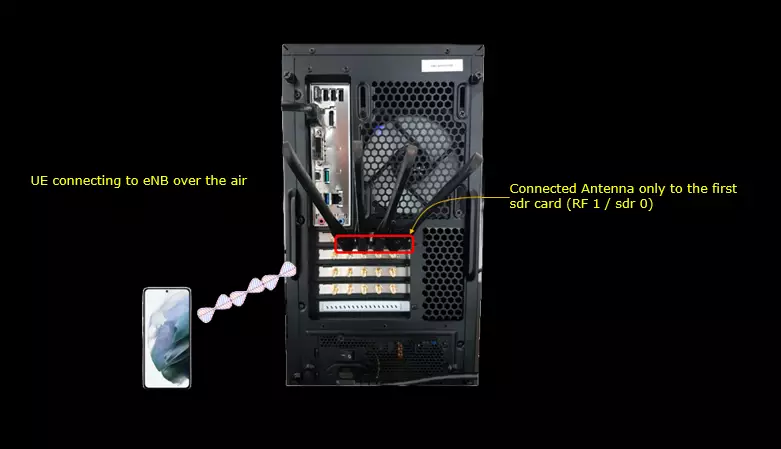
Test setup for this tutorial is as shown below.
- SIM Card used in this tutorial is the one delivered with the system as it is.
- If you want to change the configuration, The tutorial Configuration Guide would help
Only the first SDR card is cabled in this setup. The antenna goes to the RF 1 connector on that card, which is sdr 0 in the configuration file. The other cards are left unconnected.
The UE picks up the cell over the air. Everything checked in this tutorial is read out of the callbox side, so the UE does not need any special setting.
Configuration
This tutorial is checking only on SIB transmission of each radio access technology. You may use any of the configurations that you want.
NR SA Cell Reference Power
Restart lte service and go to screen window. Get the basic phy information of the cell.
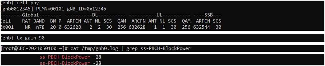
The cell phy command prints one line per cell. There is a single NR cell here, 0x001, on band n78 with 20 MHz of bandwidth. The downlink ARFCN is 632628 and the SSB sits at ARFCN 632544 with 30 kHz subcarrier spacing.
The downlink uses 2 antennas and 2 layers, the uplink 1 antenna and 1 layer, and both directions are at 256QAM. Note the bandwidth while you are here. The reference power the gNB puts into SIB1 moves with it, and that is measured later in this tutorial.

Enable SIB logging
log bcch=1 turns on the logging of the BCCH messages in the gNB. MIB and SIB1 are then written into /tmp/gnb0.log with their decoded contents. Without this, the SIB messages never reach the log file and the grep in the next step finds nothing.

Check ss-PBCH-BlockPower
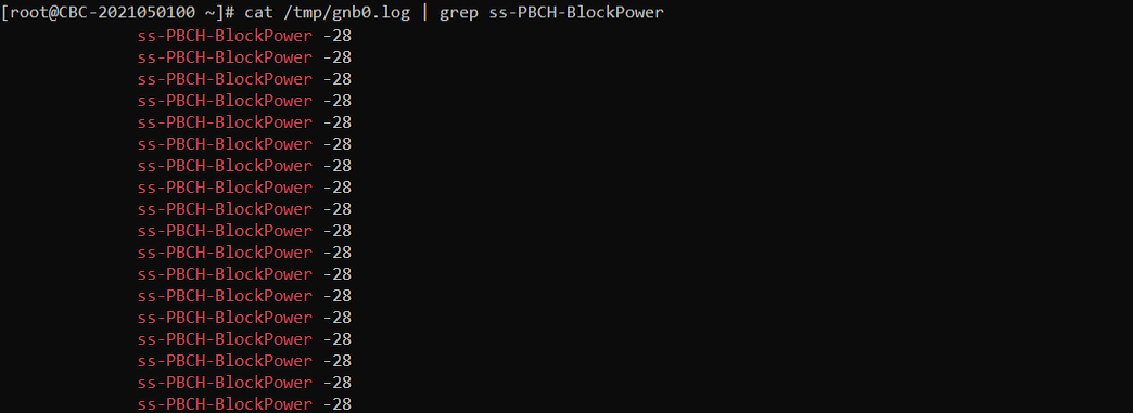
The grep pulls every ss-PBCH-BlockPower line out of /tmp/gnb0.log. All of them read -28 in this run. The value is the same in every SIB1, so one reading is enough.
Nothing was hardcoded to get this. The gNB worked the value out by itself for a 20 MHz n78 cell at the tx_gain in use. The RRC field accepts anything from -60 to 50. The next step shows where the callbox lands inside that range.
Do some experiments to find the correlation between tx power of the call box and ss-PBCH-BlockPower set by the callbox
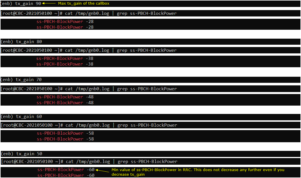
90 is the maximum tx_gain of the callbox, and at that setting ss-PBCH-BlockPower is -28. Every 10 dB taken off tx_gain takes 10 dB off the broadcast value. tx_gain 80 gives -38, 70 gives -48 and 60 gives -58.
The last step breaks the pattern. tx_gain 50 would give -68 if it kept going, but the log reads -60. -60 is the smallest value the RRC field can carry, so it stops there and does not decrease any further however far you reduce tx_gain.
Below tx_gain 60 the value in SIB1 no longer follows the real transmit power of the cell. Keep that in mind if you run a pathloss test at low power.
LTE Cell Reference Power
Restart lte service and go to screen window. Get the basic phy information of the cell.
There are two LTE cells in this run. Cell 0x001 is on band 3 with downlink ARFCN 1575, and cell 0x002 is on band 7 with downlink ARFCN 3350. Both are 20 MHz with 4 downlink antennas and 4 layers, and both use a single uplink antenna.
The two cells matter for the step after next. Each one broadcasts its own referenceSignalPower, so the grep comes back with two values and not one.

Enable SIB logging
The command is the same one used for the NR cell. For an LTE cell the decoded BCCH messages land in /tmp/enb0.log instead of /tmp/gnb0.log. Both LTE cells write into that one file.
Check referenceSignalPowerr
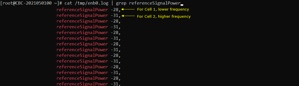
The values alternate between -28 and -31 because both cells write into the same log file. -28 belongs to cell 1 on band 3, the lower frequency. -31 belongs to cell 2 on band 7, the higher frequency.
Both cells run at the same tx_gain, so the 3 dB gap between them comes from the band. The callbox works the value out separately for each cell. Do not take one reading and assume it covers every cell on the box.
Do some experiments to find the correlation between tx power of the call box and referenceSignalPower set by the callbox
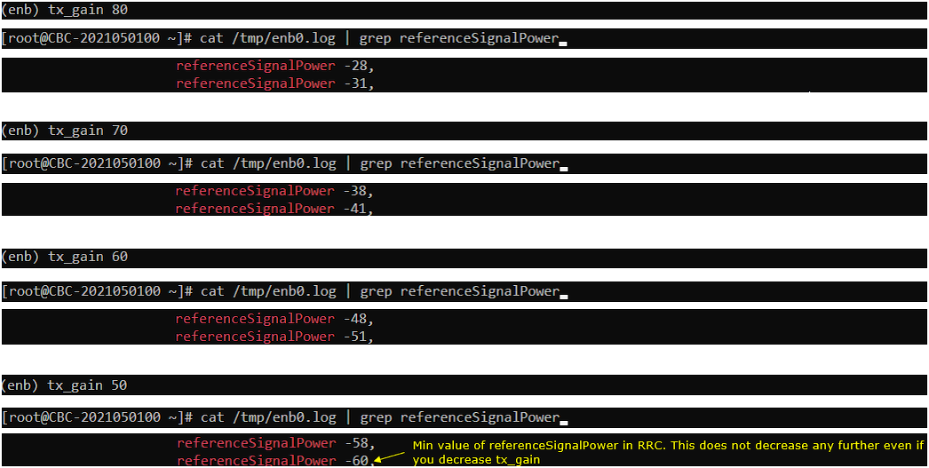
The sweep starts at tx_gain 80, where the pair reads -28 and -31. Each 10 dB step down moves both values by 10 dB. tx_gain 70 gives -38 and -41, and tx_gain 60 gives -48 and -51.
At tx_gain 50 the first cell reads -58 as expected, but the second one reads -60 instead of -61. -60 is the lowest value the RRC field accepts. Cell 2 therefore hits the floor one step earlier than cell 1, and the 3 dB gap between the two cells disappears.
NB IoT Cell Reference Power
Restart lte service and go to screen window. Get the basic phy information of the cell.
The RAT column reads NBIoT here, and there is only one cell. It is on band 20 with downlink ARFCN 6300 and uplink ARFCN 24300. The bandwidth is printed as 0.2, which is the single 180 kHz resource block an NB-IoT carrier occupies.
One antenna and one layer are used in each direction, and QAM is 4 on both links. This is the cell whose SIB2-NB carries the nrs-Power-r13 field checked further down.

Enable SIB logging
The same command applies to the NB-IoT cell. An NB-IoT cell is served by the eNB, so its BCCH messages also go into /tmp/enb0.log. The SIB2-NB content becomes readable once this is on.
Check nrs-Power
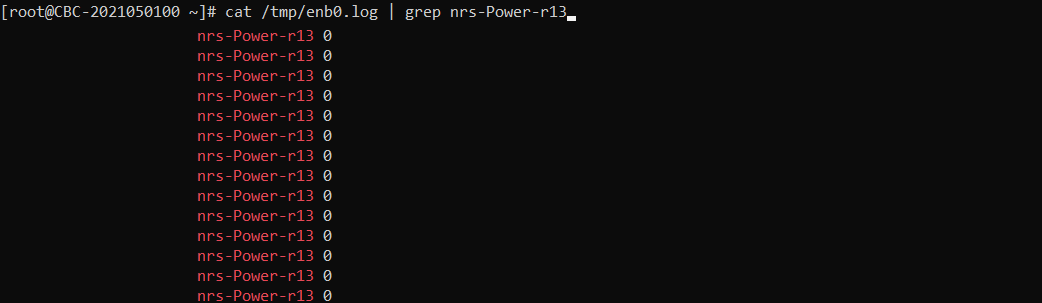
The grep runs against /tmp/enb0.log and the field name in the log is nrs-Power-r13. Every line reads 0 in this run.
0 is a real value and not a missing one. The field is signed and the RRC range is -60 to 50. A reading of 0 means the reference power works out at 0 dBm for this cell at the tx_gain in use.
Do some experiments to find the correlation between tx power of the call box and nrs-Power set by the callbox
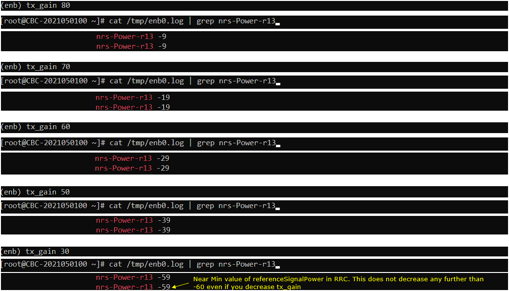
The sweep starts at tx_gain 80, where nrs-Power-r13 reads -9. Each 10 dB step down takes 10 dB off the broadcast value. tx_gain 70 gives -19, 60 gives -29 and 50 gives -39. The last step jumps straight to tx_gain 30, which gives -59.
-59 is one step short of the floor. The field cannot go below -60, so reducing tx_gain past this point leaves the broadcast value where it is while the real transmit power keeps falling. NB-IoT behaves the same way as NR and LTE here, only the field name is different.
Broadcast Reference Power Variation Among Software Release
In most cases, the reference power broadcast in SIB does not change with Software Release, but in some rare case there might be some changes in the broadcast reference power due to various reasons (e.g, Calibration table adjustment).
Following is one example of Broadcast reference power of NR Cell between the two different software release.
Release 2021-11-17 : NR SA Reference Power in SIB1
This is the reading taken on the 2021-11-17 release. The cell and the tx_gain are set the same way in both releases, so the software version is the only thing that differs between this section and the next one.
The cell is NR on band n78 with 20 MHz, downlink ARFCN 632628 and the SSB at ARFCN 632544. tx_gain is set to its maximum of 90. ss-PBCH-BlockPower comes out as -28, which is the same value measured in the NR SA section above.
Release 2022-04-01 : NR SA Reference Power in SIB1
This is the same test repeated on the 2022-04-01 release. Nothing in the cell configuration or in the tx_gain was changed, and the hardware is the same SDR50.
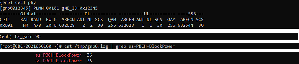
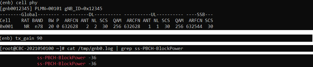
The cell phy line is identical, band n78 at 20 MHz with downlink ARFCN 632628 and the SSB at 632544, and tx_gain is still 90. ss-PBCH-BlockPower now reads -36. That is 8 dB lower than the value on the older release.
The cell is transmitting at the same power in both runs. Only the number the gNB puts into SIB1 changed. If you compare pathloss results taken on two different releases, check this value before you trust the comparison.
Broadcast Reference Power Variation with Channel Bandwidth
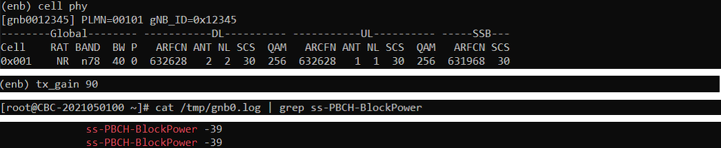
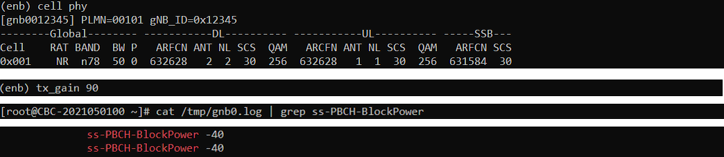
Broadcast Reference Power varies with Channel Bandwidth As shown below. This is with SDR 50 and Callbox software release 2022-04-01
The first run is the 20 MHz cell. The downlink ARFCN is 632628 and the SSB is at ARFCN 632544. tx_gain is 90 and ss-PBCH-BlockPower reads -36. This is the starting point the other two bandwidths are compared against.
The bandwidth is 40 MHz in this run. The downlink ARFCN stays at 632628 but the SSB moves down to ARFCN 631968. tx_gain is still 90, and ss-PBCH-BlockPower drops to -39, which is 3 dB below the 20 MHz value.
At 50 MHz the SSB sits at ARFCN 631584 and ss-PBCH-BlockPower reads -40, with tx_gain still at 90. That is 4 dB below the 20 MHz reading and 1 dB below the 40 MHz one. Take your reference power reading at the bandwidth you actually run the cell at.
Tips
The reference power in SIB does not follow every way of changing the cell power. The notes here cover the case where that catches people out.
Differnce Between tx_gain and cell_gain
There are roughly two different ways to change cell power. One is to use tx_gain and the other is to use cell_gain. Whenever you change tx_gain, the reference power value in SIB gets changed but cell_gain does not change the reference power value in SIB message.