Out of the Box Test - Network Monitor
The purpose of this tutorial is to show how to use Network Monitoring Functionalities.
Network Monitor in this tutorial is a software component developed by Amarisoft that can provide features listed as below.
- Shows the status of eNB/gNB and UEsim software without requiring to ssh connection to the system. You can check on those status via WebGUI
- Detects a specific event/alarm set in the configuration file and (if you want) send the those event/alarm to specific users via email
- Collect a specific set of statistics and save them as files
- Perform a certain set of operations to the system as follows.
- Restart the service
- Reboot the host
- Download / Upload configuration files
Table of Contents
Introduction
Modern mobile networks demand robust, real-time monitoring solutions to maintain service quality, optimize performance, and quickly detect and resolve faults. Network Monitor, as implemented in Amarisoft’s software suite, is a comprehensive monitoring and management component tailored for cellular network testbeds and deployments, including LTE (eNB) and 5G (gNB) base stations, as well as user equipment simulators (UEsim). Architecturally, Network Monitor operates as a middleware layer interfacing between the core network components and administrators, providing an intuitive WebGUI for status visualization and remote operations. It leverages event-driven monitoring mechanisms to detect system events, alarms, and faults, which can trigger automated notifications and actions. In addition to real-time status reporting, the software enables extensive data collection by aggregating network statistics into persistent storage for post-analysis. Its operational management capabilities further allow administrators to execute network-wide actions such as service restarts, host reboots, and configuration file management—all without requiring command-line access to network nodes. The integration of these functionalities makes Network Monitor a critical tool for ensuring high availability, reliability, and operational efficiency in both test and production environments, fitting seamlessly within the broader ecosystem of network orchestration and management frameworks.
-
Context and Background
- Network Monitor is a key component in Amarisoft's end-to-end mobile network solution, designed to streamline network operations for LTE and 5G environments.
- It bridges the gap between traditional command-line administration and modern, web-based network management.
- The software aligns with industry trends towards centralized and automated network operations, ensuring scalability and ease of management.
-
Relevance and Importance of This Tutorial
- The tutorial addresses the growing need for agile, user-friendly monitoring and control tools in complex mobile network deployments.
- It provides step-by-step guidance on leveraging Network Monitor to maximize network reliability and reduce operational overhead.
- By learning these functionalities, users can minimize downtime, improve troubleshooting efficiency, and enhance service quality.
-
Learning Outcomes
- Understanding the architecture and main features of Amarisoft Network Monitor.
- Gaining practical skills in monitoring network element status through WebGUI.
- Configuring event and alarm detection, and setting up automated notifications.
- Collecting, saving, and analyzing network statistics for performance optimization.
- Executing remote operational procedures such as service restarts, host reboots, and configuration file management.
-
Prerequisite Knowledge and Skills
- Basic understanding of LTE/5G network architecture and terminology.
- Familiarity with Amarisoft software components (eNB, gNB, UEsim) is beneficial.
- Experience with web-based user interfaces and general network administration concepts.
- Access privileges for administering the Amarisoft platform and its monitoring tools.
Summary of the Tutorial
This tutorial provides detailed procedures for setting up, running, and testing the Network Monitor component, as well as configuring alarm notifications and statistics collection. The summary below focuses on the methodologies and test steps covered in the content.
-
Test Setup
- Utilize the default configuration file (cfg) without making modifications for out-of-the-box testing.
- Use the SIM card provided with the system.
- Reference Information_Config_Guide.pdf for custom configuration if required.
-
Running Monitor in WebGUI
- Ensure Monitor is installed and executed as part of the LTE service; start or restart lteservice to enable it.
- Access the WebGUI to verify the MONITOR component appears.
- Set filters specific to the MONITOR log for focused log viewing.
- Optionally, display only MONITOR logs by specifying relevant layers.
-
Using MONITOR Functions
- Navigate to the MONITOR tab to view and manipulate different components.
- Right-click on the root node or individual components to access context menus for additional actions. Menu items are self-explanatory and facilitate component management.
-
Setting Up Email for Alarm Notification
- Configure the email sender account in /root/monitor/ssmtp.conf.
- Use the provided test-email.sh script in the /root/monitor directory to send a test email and validate the setup.
- Confirm receipt of the test email to ensure email functionality before configuring alarms.
-
Alarm Notification Testing
-
Alarm Notification - Test 1
- Configure the desired alarm event in monitor.cfg.
- Specify the sender ([from]) and recipient ([to]) email addresses in the configuration; sender email must match the one in ssmtp.conf.
- Start the LTE service and verify MONITOR operation.
- Induce an alarm condition by intentionally killing the IMS process to trigger the configured alarm.
- Observe error logs and confirm the receipt of an email notification when the alarm is triggered.
-
Alarm Notification - Test 2
- Repeat the alarm configuration and email specification in monitor.cfg, using a different recipient email address (possibly with a different domain).
- Start the LTE service and ensure MONITOR is running.
- Trigger the alarm by terminating the IMS service via the screen console ([Ctrl + C] on the IMS console).
- Verify that MONITOR logs the error and that the email notification is received upon alarm activation.
-
Alarm Notification - Test 1
-
Statistics Collection Testing
-
Statistics - Test 1
- Enable and configure the statistics parameters in monitor.cfg, specifying collection intervals, storage directory, and retention period.
- Run MONITOR and verify that a directory is created as per the 'store' parameter.
- Check that subdirectories and statistics files are generated at the configured intervals.
- Open the statistics files to confirm data is output in JSON format.
- Optionally, process or format the JSON file for readability or further analysis using custom scripts.
-
Statistics - Test 1
Overall, the tutorial guides the user through system setup, log filtering, alarm and email notification configuration, and statistics collection, providing practical steps and validation methods for each process.
Before you start
Since Network Monitor is not the default components of the installation package, you need to check if your system is installed with network monitor or not before you try anything in this tutorial. Check the tutorial : Installation_Monitor for this check up.
Test Setup
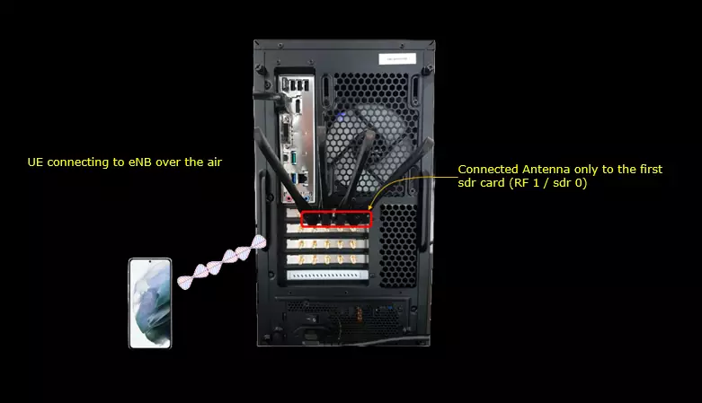
Test setup for this tutorial is as shown below. (NOTE : Basically it doesn't matter with exact hardware setup to utilize the Command Line Commands. You can use the information in this page for any test setup you are using)
- Since this test is for Out of the box testing, I used the default configuration(cfg) file without changing anything in it
- SIM Card used in this tutorial is the one delivered with the system as it is.
- If you want to change the configuration, The tutorial Information_Config_Guide.pdf would help
The antenna is connected only to the first SDR card, which is RF 1 / sdr 0. The UE reaches the eNB over the air from that single antenna.
Run Monitor in WebGUI
If Monitor installation is properly done, the monitor is executed as part of lte service. no specialy procedure is required for monitor execution only. Just start or restart the lteservice as follows.
service lte restart redirects to systemctl restart lte.service, and that brings MONITOR up together with the other components. screen -r then attaches to the console session so you can watch each one start.

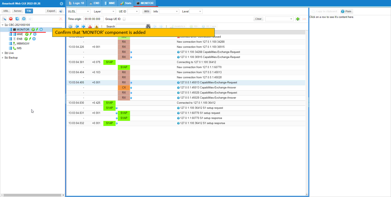
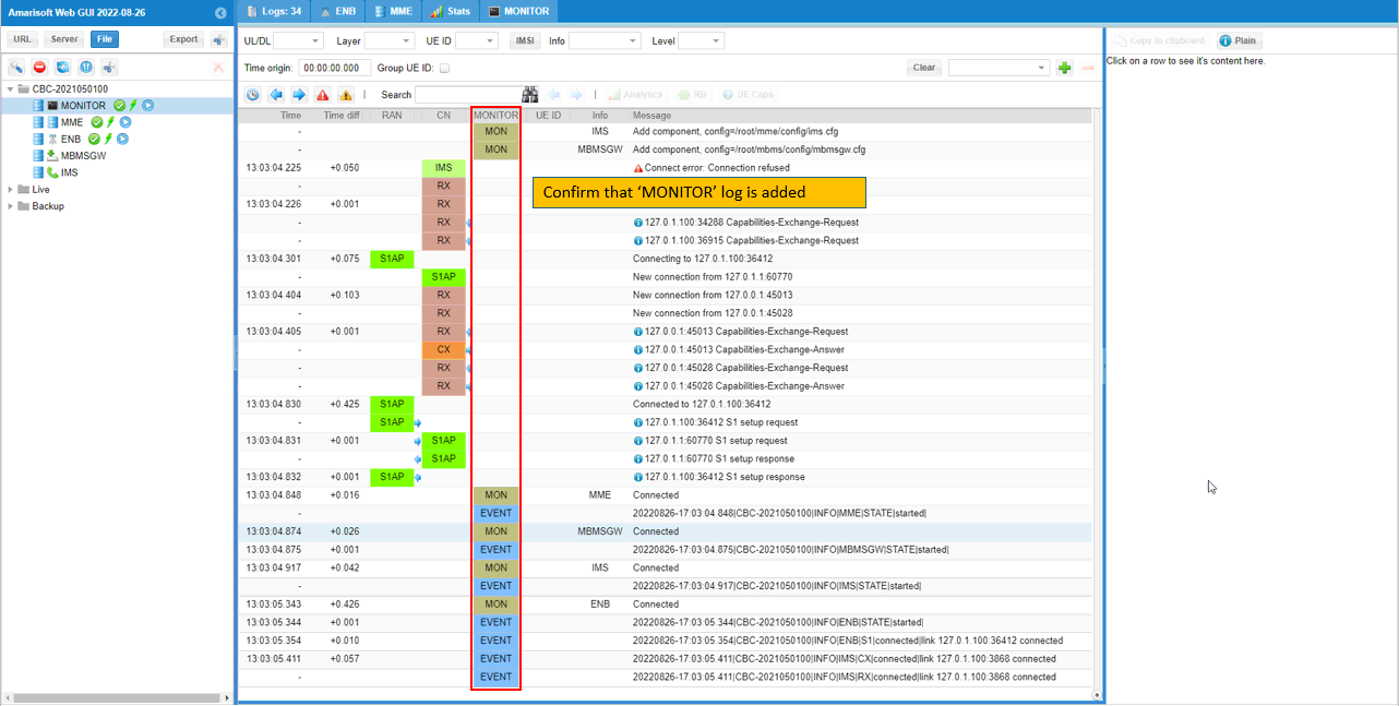
If you open up WebGUI, you would see 'MONITOR' component is added as shown below.
MONITOR appears at the top of the component tree on the left, above MME, ENB, MBMSGW and IMS. It also takes its own tab in the top bar, next to Logs, ENB, MME and Stats.
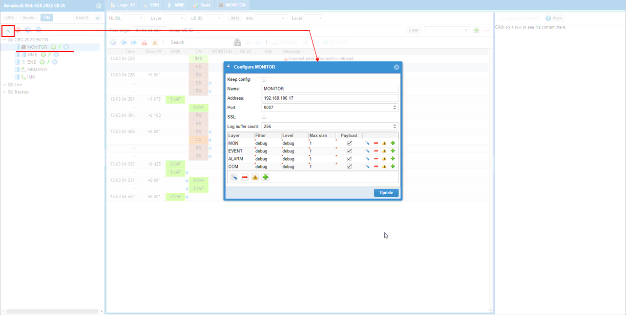
You may set the filters for MONITOR log as shown below.
The Configure MONITOR dialog opens from the wrench icon at the top left of the component tree. Address is 192.168.100.17 and Port is 9007, which is the address MONITOR listens on. SSL is off and Log buffer count is 256.
The table at the bottom is the filter itself. MONITOR has four layers: MON, EVENT, ALARM and COM. Each row carries its own Filter, Level, Max size and Payload setting. All four are set to debug here, with Max size 1 and Payload enabled. Press Update to apply them.
The Logs panel has 'MINITOR' column and the MONITOR log is printed as shown below.
The MONITOR column sits between CN and UE ID. The MON rows report component level state. Each component gets an Add component row naming its config file, and a Connected row once it attaches.
The EVENT rows carry the formatted event text. Each one holds a timestamp, the host name CBC-2021050100, a level such as INFO, then the component, the section and the state, all separated by the pipe character. The ENB entry reports S1 connected to 127.0.1.100:36412, and the IMS entries report CX and RX connected to 127.0.1.100:3868.
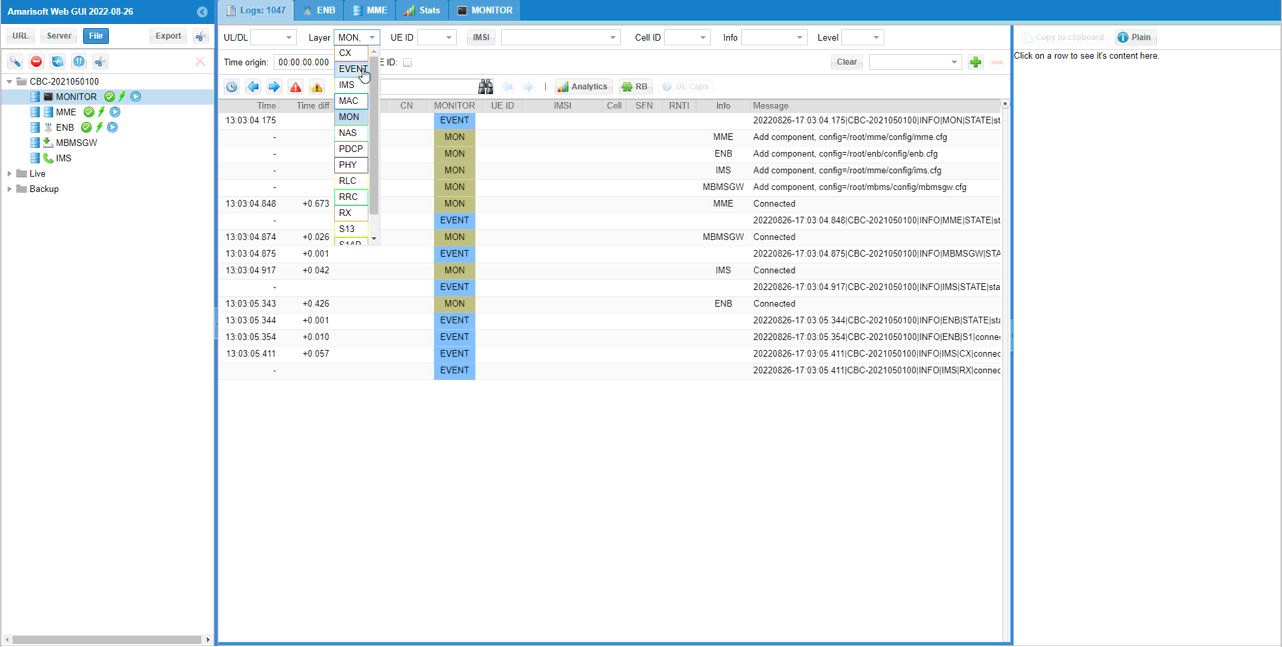
[Optional] If you want to display MONITOR log only, you may specify layers which belong to MONITOR component.
The Layer drop down lists every layer the WebGUI knows about, so CX, IMS, MAC, NAS, PDCP, PHY, RLC, RRC, RX and S13 all appear in the same list. The two that belong to MONITOR are MON and EVENT, and both are picked here.
Once that filter is applied, only the MONITOR rows are left in the Logs panel. That is the quickest way to read the monitor output when the other components are producing a lot of traffic.
Functions in MONITOR
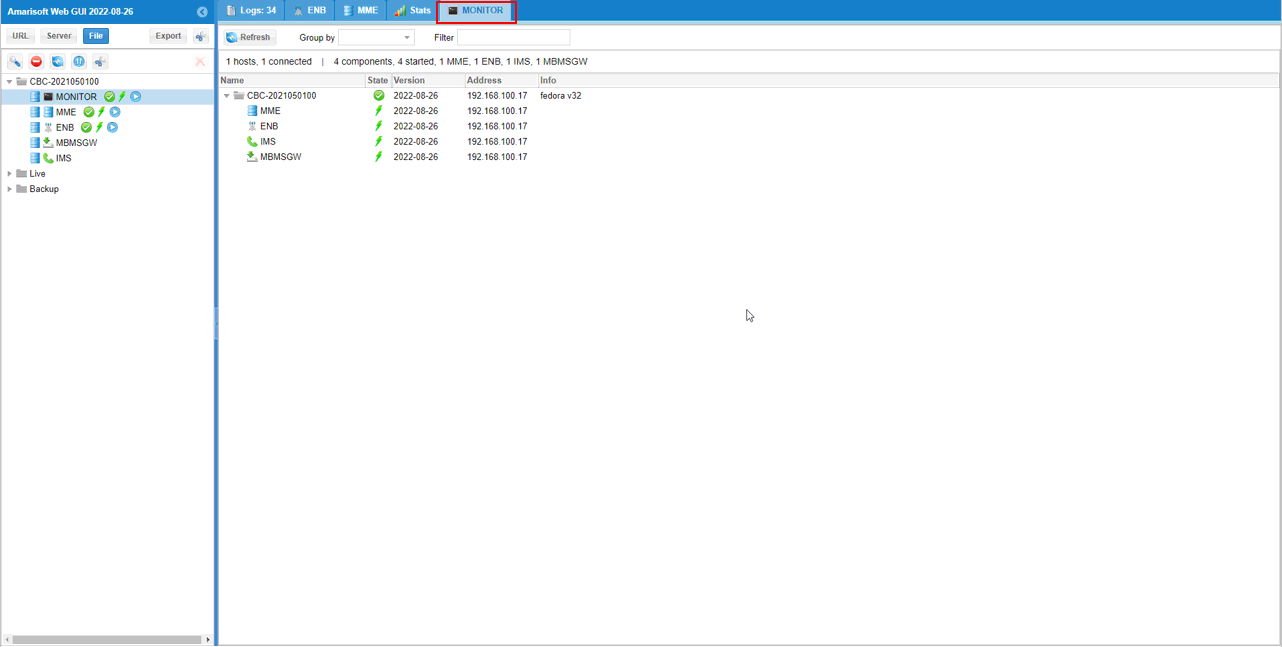
If you go into MONITOR tab, you would have the list of the components you can manipulate with monitor as shown below.
The summary line above the list reads 1 hosts, 1 connected and 4 components, 4 started, then counts them out as 1 MME, 1 ENB, 1 IMS and 1 MBMSGW.
Each row carries Name, State, Version, Address and Info. All four components run version 2022-08-26 at 192.168.100.17, and the host row reports fedora v32. Refresh reloads the list, and the Group by and Filter boxes narrow it down once more than one host is connected.
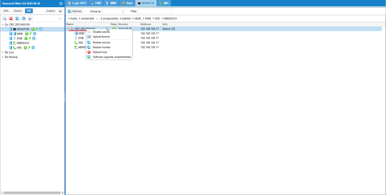
If you right mouse click on the root node of the list, you would get a menu as shown below. I think each of the menu items are self explanatory and you may not need any further explanation.
The items are Disable alarms, Upload license, Restart service, Restart monitor, Reboot host and Software upgrade (experimental). They all act on the whole host, because this is the root node.
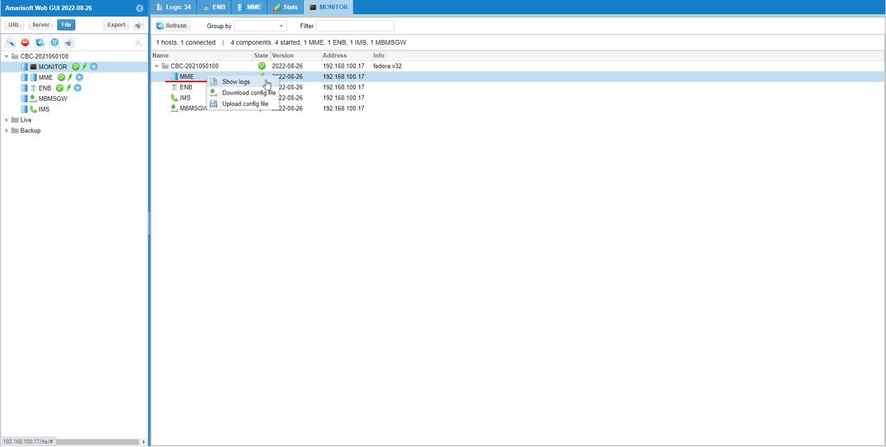
If you right mouse click on the each component in the list, you would get a menu as shown below. I think each of the menu items are self explanatory and you may not need any further explanation.
The per component menu is shorter, with Show logs, Download config file and Upload config file. These act only on the row you clicked, which is MME here.
Setting Up Email for Alarm Notification
For now, Alarm is notified only by email. so you need to make it sure that the email is working properly with your system before you configure any alarm. This section would explain on how to configure email and test if email works or not.
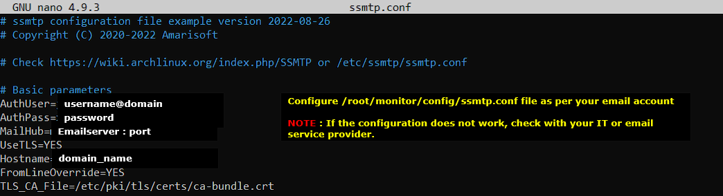
First, configure email in /root/monitor/ssmtp.conf as shown below. This is just a template and don't copy & paste it as it is. The configuration in this file is for Sender email account for the alarm notification email.
The parameters to fill in are AuthUser and AuthPass for the sending account, and MailHub for the mail server and its port. Hostname takes your domain name.
UseTLS is YES and FromLineOverride is YES in this template, and TLS_CA_File points at /etc/pki/tls/certs/ca-bundle.crt. If the settings do not work, these are the values your IT department or your email provider has to confirm.
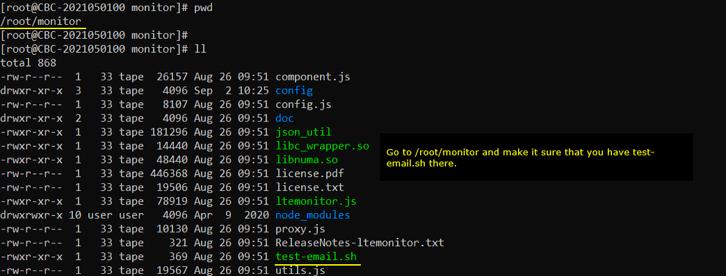
If you go to /root/monitor directory, you would find the email test script : test-email.sh as shown below.
The same directory holds ltemonitor.js, component.js, proxy.js and json_util, plus the doc and config subdirectories. The config subdirectory is the one that holds ssmtp.conf, alarm.tpl and monitor.cfg.
test-email.sh is executable, so you can run it straight from here.
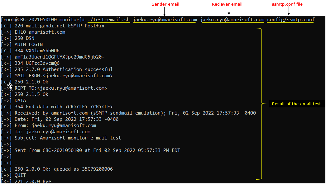
Try send a test email as shown below. (
test-email.sh takes three arguments in order: the sender address, the receiver address, and the ssmtp configuration file to use.
The script then prints the whole SMTP exchange. Two lines are worth checking. 235 2.7.0 Authentication successful means AuthUser and AuthPass are right. 250 2.0.0 Ok: queued means the server accepted the message. The session closes with 221 2.0.0 Bye.
The mail it sends carries the subject Amarisoft monitor e-mail test, and a body naming the host and the time.
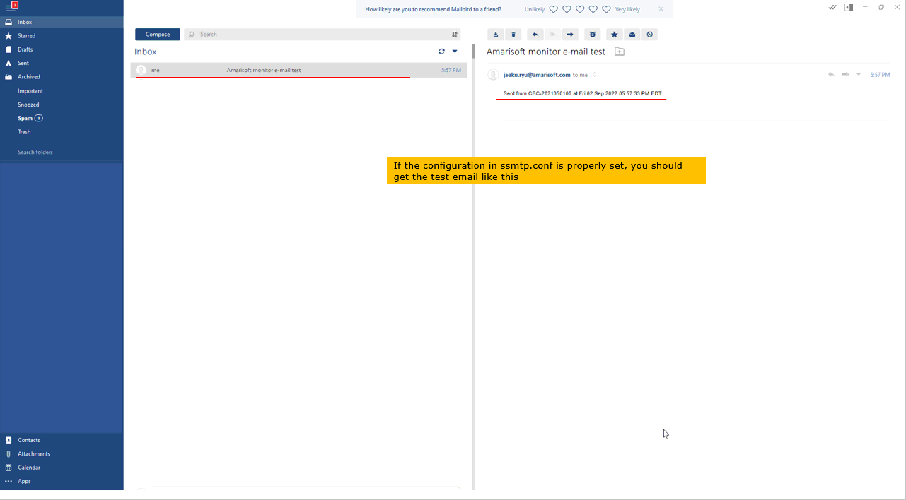
You would get the test email as shown below if the email setup (ssmtp.conf) is properly done.
The subject is Amarisoft monitor e-mail test and the body is one line naming the host CBC-2021050100 and the time it was sent. This script only proves that the transport works, so there is nothing else in the message.
Setting Up Alarm Notification
Once you comfirmed that the email is working as in previous section, you can now specify a specific alarm in monitor.cfg and get notified by the email whenever the alarm condition is met.
Alarm Notification - Test 1
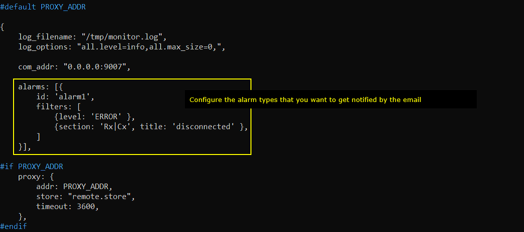
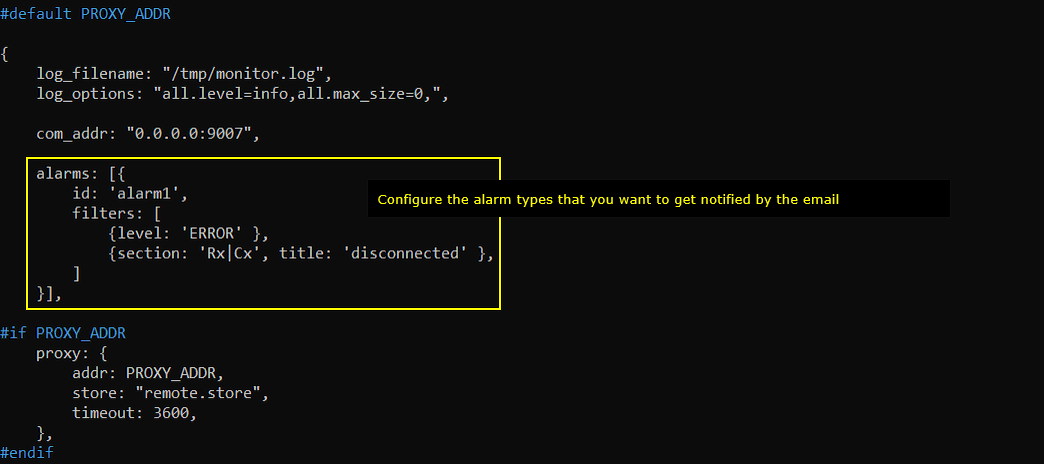
Configure the alarm in monitor.cfg which you want to get notifified about. This is just an example of the possible alarms and you can find various other types of alarms in ltemonitor document.
The alarms array holds one entry with id 'alarm1'. Its filters list carries two conditions. The first matches any entry whose level is 'ERROR'. The second matches section 'Rx|Cx' with title 'disconnected'.
The rest of the file is not part of the alarm setup. log_filename is /tmp/monitor.log and log_options is all.level=info,all.max_size=0. com_addr is 0.0.0.0:9007, the address the WebGUI connects to. The proxy block applies only when PROXY_ADDR is defined, so it does nothing in this test.
This filters list is what you change to be notified about something else. alarms is an array, so you can add further entries with their own id.
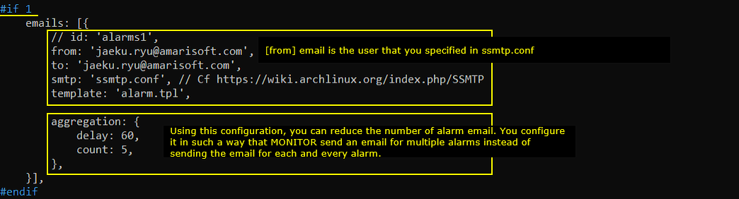
Now specify email in monitor.cfg as shown below. You should specify [from] parameter with the email you configured in ssmpt.conf, but you can configure any valid email in [to] parameter.
The emails array carries from, to, smtp and template. smtp points at ssmtp.conf, the same file you tested in the previous section. template points at alarm.tpl, which decides the layout of the notification.
The aggregation block underneath sets delay to 60 and count to 5. With that in place MONITOR groups alarms together instead of sending one email per alarm. That keeps the mailbox usable when a single fault produces a burst of errors.
The id field is commented out in this example.
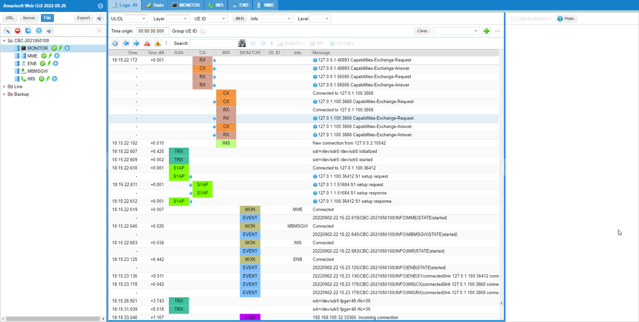
Now start lte service and make it sure that MONITOR and other components are running.
The component tree on the left carries MONITOR, MME, ENB, MBMSGW and IMS with their running icons, and the top bar has a tab for each one.
In the log itself the MON rows report Connected for MME, MBMSGW, IMS and ENB in turn, and each is followed by an EVENT row ending in STATE|started. The TRX rows above them report sdr /dev/sdr0 initialized and then started.
Now let's try to make an intentional error that would trigger the alarm (
ps a lists the running processes. Each component runs as a pair: a ltelaunch.sh shell started by OTS, and the component binary itself. The IMS binary here is ./lteims config/ims.cfg with PID 897919.
That PID is what the next step needs. It changes every time the service restarts, so read it from your own listing instead of reusing an old number.
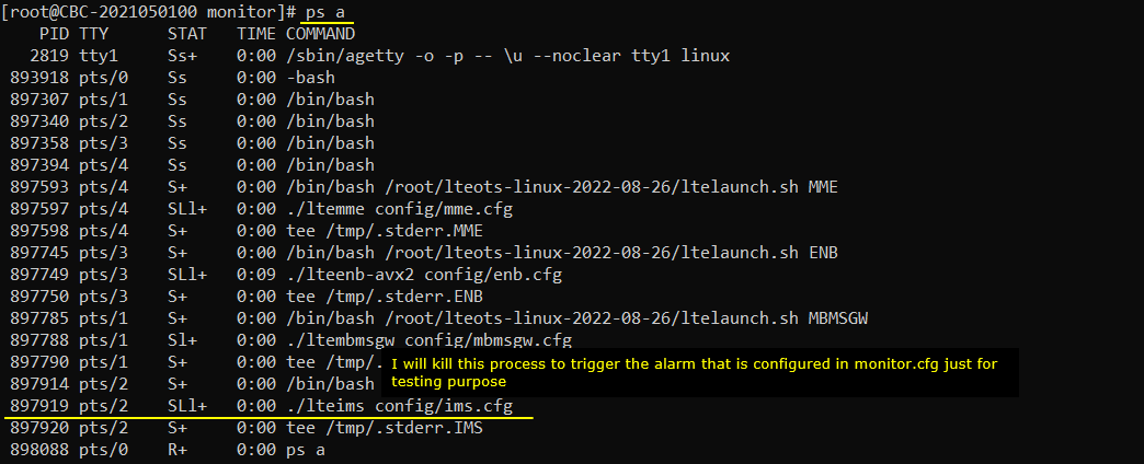
Kill the IMS process.
kill is given the PID that ./lteims was running under in the listing above. No signal option is used, so the default is sent.

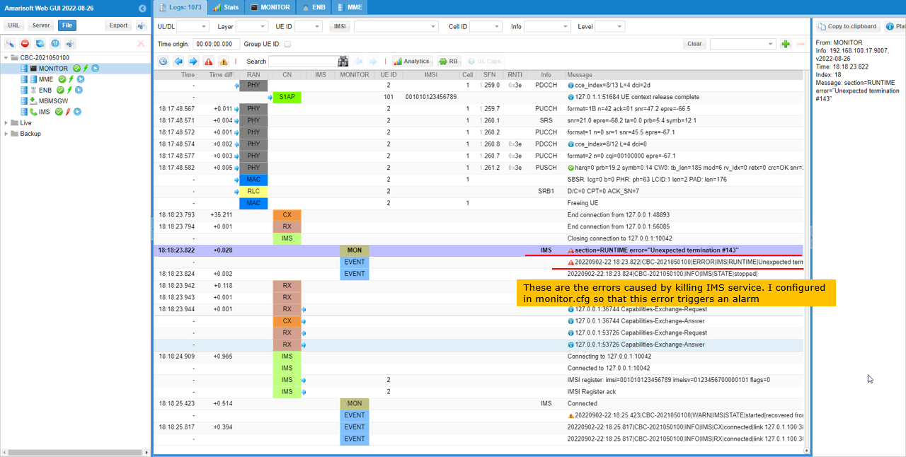
Now you would see the error message printed MONITOR log. (
The MON row that matters reads section=RUNTIME error="Unexpected termination #143" against the IMS component. The EVENT row below it repeats the same text at ERROR level, and the next EVENT row reports IMS|STATE|stopped.
This is the entry the filter matches, because its level is ERROR. The detail panel on the right names MONITOR as the source and gives the index and the time of the entry.
The recovery is visible a little further down. IMS reconnects, the CX and RX links to 127.0.1.100:3868 come back, and a WARN row reports STATE|started|recovered.
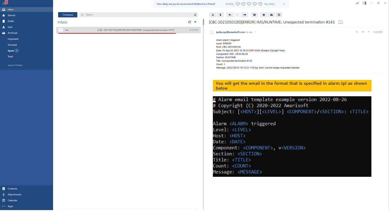
Once the alarm is triggered, you would receive the email notification as shown below.
The subject is assembled from the host, the level, the component, the section and the title, so it reads [CBC-2021050100][ERROR] IMS/RUNTIME: Unexpected termination #143. The body repeats those as labelled lines and adds Date, the component version, Count and the original Message.
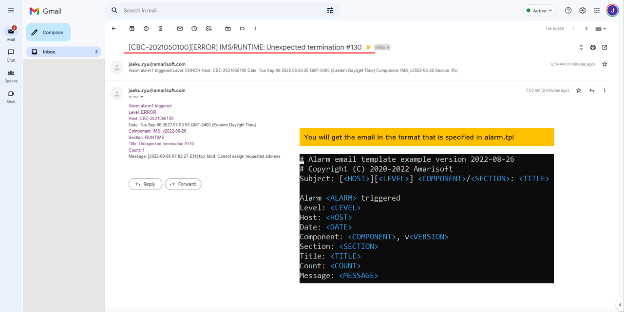
The layout comes from alarm.tpl. That file is a plain template with placeholders such as <HOST>, <LEVEL>, <COMPONENT>, <SECTION>, <TITLE>, <COUNT> and <MESSAGE>. Edit it if you want the notification in a different shape.
Count reads 1 here, because only one alarm was collected before the email went out.
Alarm Notification - Test 2
This example is almost same as the previous example. The only difference is the different [to] email is used (in this example, the email with different domain name than [from] email) and the method to trigger alarm is different.
Configure the alarm in monitor.cfg which you want to get notifified about. This is just an example of the possible alarms and you can find various other types of alarms in ltemonitor document.
The alarms block is unchanged from Test 1. alarm1 still filters on level 'ERROR' and on section 'Rx|Cx' with title 'disconnected'. Only the email destination and the way the fault is produced change in this test.
Now specify email in monitor.cfg as shown below. You should specify [from] parameter with the email you configured in ssmpt.conf, but you can configure any valid email in [to] parameter.
The to address is now a gmail.com account, while from stays on the amarisoft.com account set in ssmtp.conf. That is the point of this test. The receiver does not have to share the sender's domain.
smtp, template and the aggregation values of delay 60 and count 5 are the same as in Test 1.
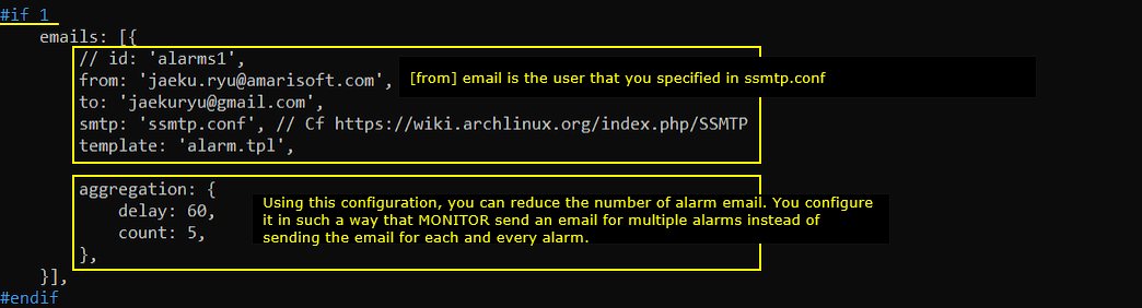
Now start lte service and make it sure that MONITOR and other components are running.
The startup runs the same way as in Test 1. The MON rows report Connected for MME, MBMSGW, IMS and ENB, and the matching EVENT rows end in STATE|started.
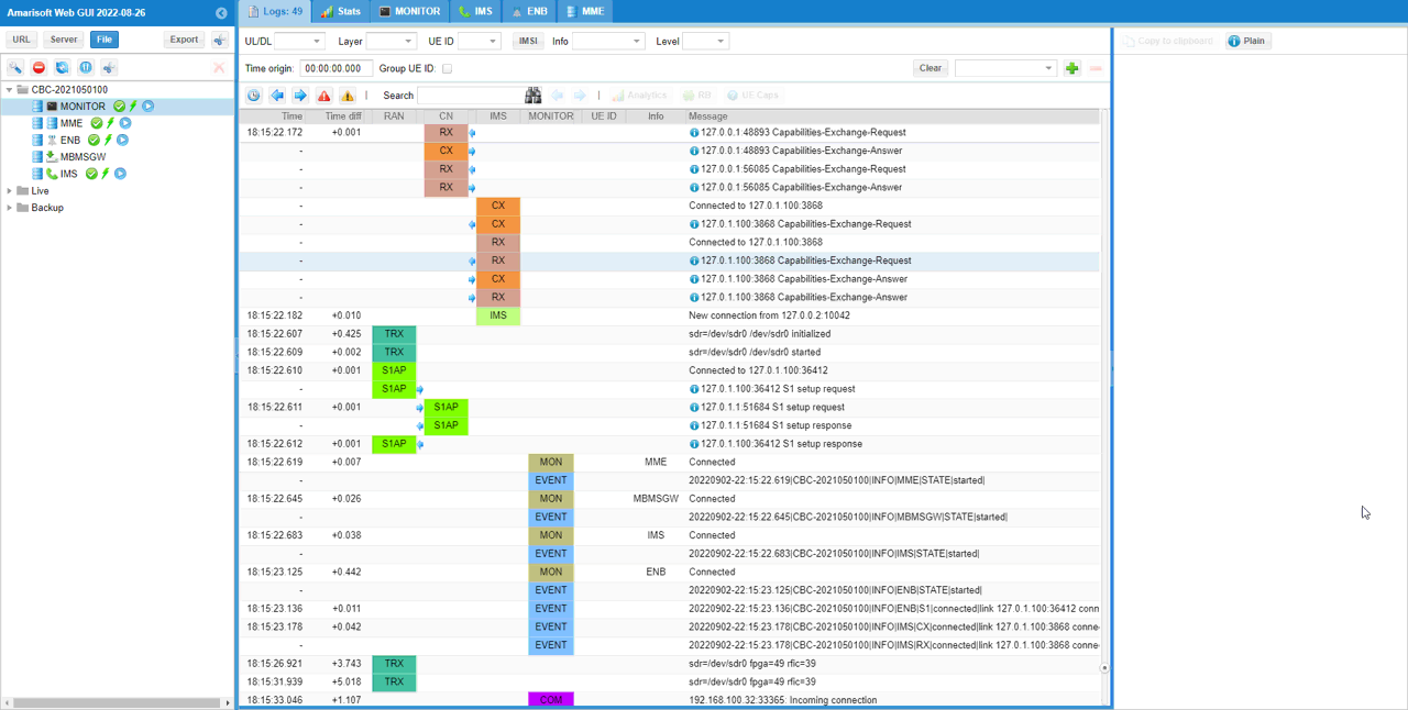
Now let's try to make an intentional error that would trigger the alarm (
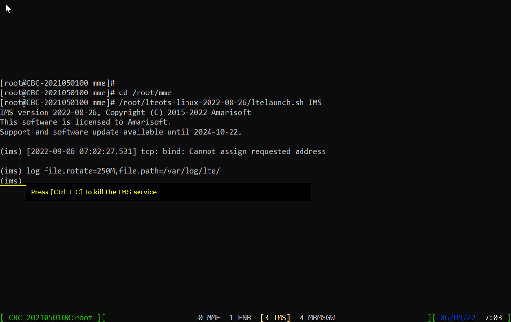
First switch to [IMS] console and Press [Ctrl + C]
The screen session gives each component its own console. The status bar along the bottom lists them as 0 MME, 1 ENB, 3 IMS and 4 MBMSGW, and the one in brackets is the window you are attached to.
The prompt inside it is (ims). Pressing Ctrl + C at that prompt stops IMS from its own console, so you do not have to look up a PID first.
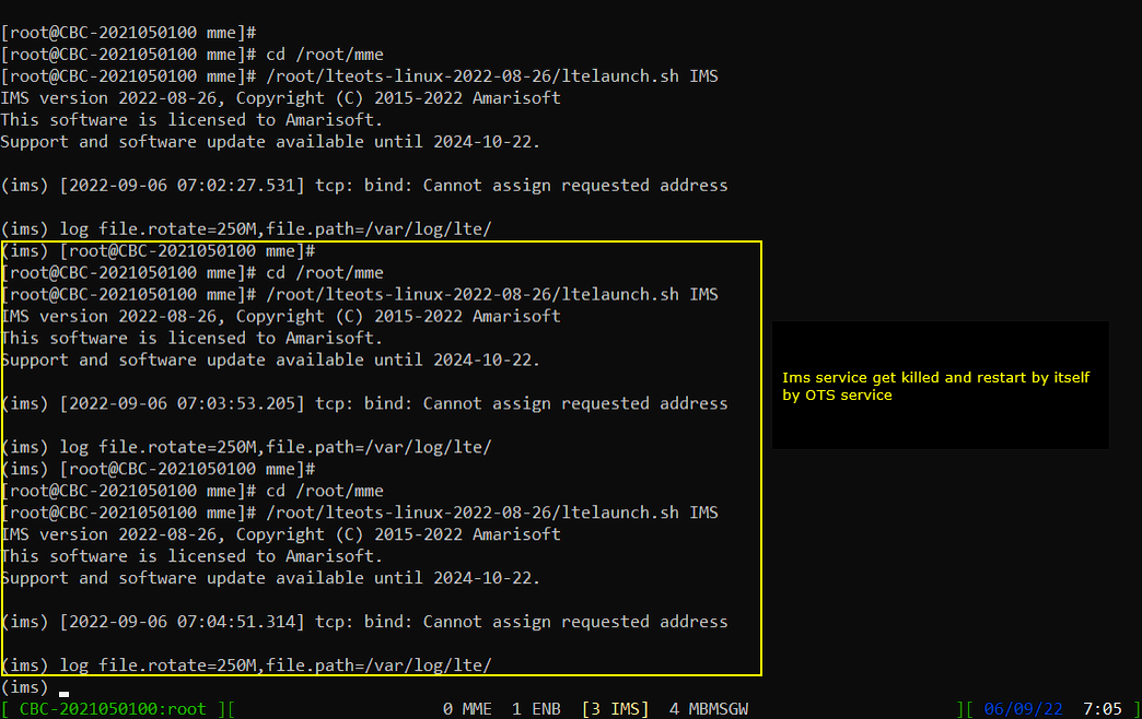
IMS service get killed and gets restarted soon by OTS service.
The restart shows up as the whole IMS banner appearing again in the same console. The version line, the licence lines and the log settings are reprinted every time.
The timestamps show how quickly it comes back. The first start is at 07:02:27.531, the next at 07:03:53.205 and a third at 07:04:51.314. OTS relaunches the component without any action from you.
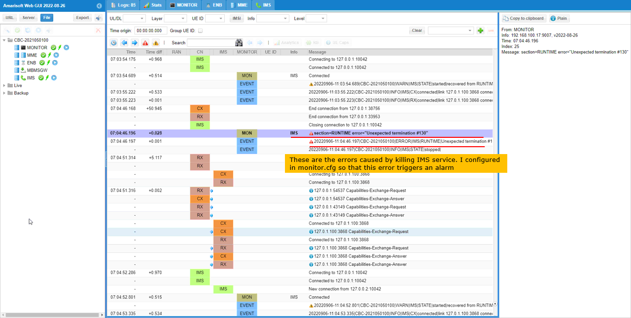
Now you would see the error message printed MONITOR log.
The MON row reads section=RUNTIME error="Unexpected termination #130" for IMS, and the EVENT rows below repeat it at ERROR level and then report IMS|STATE|stopped.
The termination number is 130 here rather than the 143 of Test 1. The alarm does not depend on that number. It is the ERROR level that the filter matches.
The WARN rows above and below the error end in started|recovered, and those mark the restarts that OTS performed.
Once the alarm is triggered, you would receive the email notification as shown below.
The mail arrives in the gmail.com inbox. That confirms the to address can sit on a different domain from the sender. Its subject reads [CBC-2021050100][ERROR] IMS/RUNTIME: Unexpected termination #130.
Two alarm mails are in the thread, one at 6:54 and one at 7:03, matching the repeated restarts. The body follows alarm.tpl the same way as before, and Count reads 1.
Setting Up Statistics
You can let MONITOR generate statistics data in certain interval that you want. In this section, I will show you how to enable 'statistics data collection'.
Statistics - Test 1
You can enable (configure) stats parameter in monitor.cfg as shown below. You can specify when the stat data should be collected, where the data should be stored and how long those files should be reserved. (
time is set to "*:*:0" in hh:mm:ss CRON style, so a stat file is written every minute. utc is true. timeout is 600 * 10, so 6000 seconds. That is how long a file is kept before it is removed. store is 'stats', the name of the directory the files go into.
Change time if you want a different interval, and timeout if you want the files to survive longer.

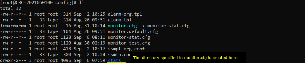
Once MONITOR runs, you would see a new directory is created as specified in 'store' parameter in monitor.cfg as shown below.
The stats directory appears in the config directory, next to the files MONITOR reads. The same listing holds alarm.tpl and ssmtp.conf.
monitor.cfg itself is a symbolic link, and here it points at monitor-stat.cfg. That is worth checking before you edit anything, because editing monitor.cfg edits whatever the link points to. The directory also holds monitor-test.cfg and monitor.default.cfg.
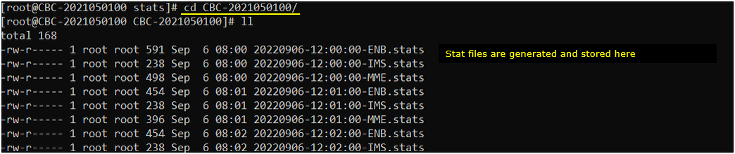
You would see another subdirectory is created in stats (store directory) as shown below.
The subdirectory is named after the host, so it is CBC-2021050100 here. It is created when the first stat file is generated, not when MONITOR starts.

within the subdirectory, you would see the statistic data gets stored with the intervals specified in monitor.cfg.
The file name is the timestamp followed by the component, so 20220906-12:00:00-ENB.stats holds the ENB data for that minute. Every minute produces one file per component, and ENB, IMS and MME each get their own.
The sizes differ by component. The ENB files run between 454 and 591 bytes here, the MME files sit around 400 to 500, and the IMS files are 238.
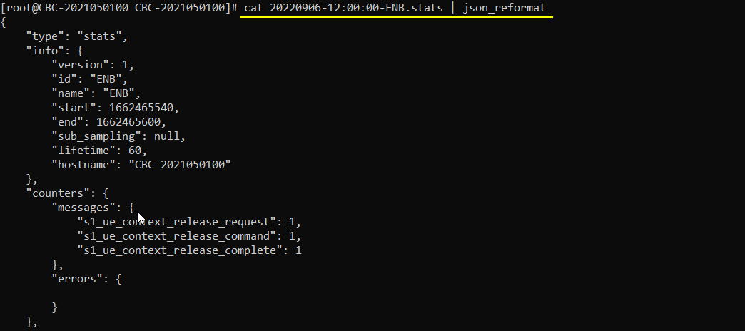
If you open up the file, you would see the information printed in JSON format as shown below.
The whole file is a single line, so an editor gives you one long row. The start of it sets type to stats and then opens info with version, id, name, start and end.
start and end are Unix timestamps. They are how you match a file back to the minute it covers.

You can print the json file in more readable format as shown below (
json_reformat takes that single line on standard input and prints it indented. Piping cat into it is enough.
The info block gives version 1, id and name ENB, start 1662465540 and end 1662465600, lifetime 60 and the hostname. The 60 second gap between start and end is the collection interval set by time in monitor.cfg.
counters is the part you will actually read. Under messages, this file recorded s1_ue_context_release_request, s1_ue_context_release_command and s1_ue_context_release_complete once each. The errors block is empty for this minute.