LTE Custom Frequency
This tutorial show you how to define LTE band and earfcn which is not defined in 3GPP. Amarisoft SDR can roughly support any frequency between 500Mhz and 6 Ghz without any external Up/Down converter. So you can set any frequency within that range regardless of whether it is defined in 3GPP or not.
If any specific frequency and band is defined in 3GPP, you can just specify the band and earfcn as specified in 3GPP. But if you want to use any other frequency region which are not defined in 3GPP, you can define your own band and earfcn as will be shown in this tutorial.
Table of Contents
- LTE Custom Frequency
Introduction
In modern wireless communications, the allocation and configuration of operating frequency bands and channel numbers are foundational for network deployment and interoperability. The Long Term Evolution (LTE) standard, as defined by the 3rd Generation Partnership Project (3GPP), specifies a comprehensive set of frequency bands and corresponding EARFCN (E-UTRA Absolute Radio Frequency Channel Number) mappings to ensure global harmonization and device compatibility. However, there are scenarios in research, development, and specialized deployments where operation outside the predefined 3GPP bands is necessary—such as experimental networks, private LTE installations, or spectrum innovation. Amarisoft Software Defined Radio (SDR) platforms offer unique flexibility by supporting a broad frequency range, typically from 500 MHz to 6 GHz, without the need for external radio frequency converters. This capability enables users to define and operate custom LTE frequency bands and EARFCN values beyond the standard 3GPP specifications, facilitating advanced prototyping and non-standard deployments. Understanding the underlying architecture of LTE band and EARFCN allocation, the mapping mechanisms, and the significance of flexible SDR platforms is crucial for professionals aiming to leverage custom spectrum configurations. This tutorial provides a comprehensive guide to defining and configuring LTE bands and EARFCN values not defined in 3GPP, specifically using the Amarisoft SDR ecosystem, and highlights the broader implications for wireless research and innovation. The concepts presented herein also extend to New Radio (NR/5G) custom frequency configuration, underscoring the evolving nature of software-defined wireless infrastructure.
-
Context and Background
- LTE frequency bands and EARFCN values are standardized by 3GPP to ensure interoperability across devices and regions.
- Amarisoft SDR supports a wide RF range (500 MHz to 6 GHz) without requiring additional hardware, enabling operation in both standard and custom frequency regions.
- Custom band and EARFCN configuration is essential for research, private networks, and experimental deployments not bound by regulatory or standardization constraints.
-
Relevance and Importance of the Tutorial
- Enables users to set up LTE networks on non-standard frequencies for testing, innovation, or private use cases.
- Empowers rapid prototyping and experimentation with spectrum not covered by current 3GPP allocations.
- Facilitates understanding of SDR flexibility and the practical aspects of wireless system configuration.
-
Learning Outcomes
- Gain in-depth knowledge of the relationship between frequency bands, EARFCN, and LTE architecture.
- Understand how to define custom LTE bands and EARFCN values on Amarisoft SDR.
- Acquire hands-on skills for configuring and deploying LTE networks outside of standardized frequency allocations.
- Learn about the extension of these concepts to NR (5G) custom frequency setups.
-
Prerequisite Knowledge and Skills
- Familiarity with basic LTE concepts, including frequency bands and channel numbering.
- General understanding of SDR (Software Defined Radio) principles and Amarisoft platform basics.
- Awareness of wireless network configuration and system deployment procedures.
- Basic proficiency in working within a Linux environment and editing configuration files.
Summary of the Tutorial
This tutorial outlines the procedure for configuring and verifying a custom LTE frequency band and EARFCN using the Amarisoft eNB software. The following summarizes the test setup, configuration steps, and test verification methodology as described in the tutorial.
-
Test Setup
- The test does not utilize a commercial UE, as commercial devices do not support non-3GPP bands or custom EARFCNs.
- The setup is based on a callbox and SDR platform, as depicted in the provided diagram.
-
Key Configuration Parameters
-
The main configuration involves defining custom_freq_band and associated parameters, including:
- band
- dl_earfcn_min / dl_earfcn_max
- ul_earfcn_min / ul_earfcn_max
- dl_freq_min / ul_freq_min
- These parameters are set according to the desired custom frequency allocation, referencing Amarisoft documentation for details.
-
The main configuration involves defining custom_freq_band and associated parameters, including:
-
Configuration Procedure
- The configuration file enb-custom-band.cfg is used, which is derived from the default configuration.
- A new TDD flag option is added for custom frequency support.
- Custom band and EARFCN values are explicitly defined, mapping absolute frequencies to EARFCNs as per 3GPP incremental steps.
- The custom EARFCN values are applied to both downlink and uplink configuration fields.
-
Test Procedure (Run and Check)
- The LTE service is launched, and the eNB is monitored via the screen interface.
- The default printout in the eNB screen is used to confirm the configured band and frequency.
- The [cell phy] command is executed to verify ARFCN configuration.
- Frequency settings are cross-checked using the rf_info command.
- Verification is performed to ensure the custom band is broadcast in SIB1 (System Information Block 1), specifically by checking the freqBandIndicator information element.
The test methodology focuses on configuration validation through internal software commands and outputs, rather than interoperability with commercial UE devices.
Test Setup
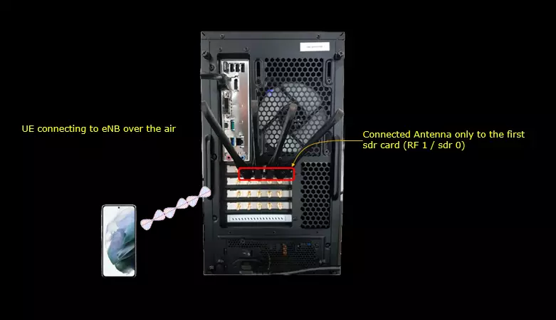
I would not use the UE here since commercial UE would not support non-3GPP band and earfcn.
Only the Callbox with its SDR card is used in this test. No UE attaches to the cell. All the checks in this tutorial are done on the eNB console and in the eNB log.
Key Configuration Parameters
Followings are important configuration parameters for this tutorial. You may click on the items for the descriptions from Amarisoft documents.
- custom_freq_band: In this link, you will get the descriptions for all the items listed below.
- band
- dl_earfcn_min
- dl_earfcn_max
- ul_earfcn_min
- ul_earfcn_max
- dl_freq_min
- ul_freq_min
- dl_earfcn
- ul_earfcn
Configuration
I am using enb-custom-band.cfg which is copied and modified from enb.default.cfg

I added a new TDD flag option as shown below. I added an option for custom frequency to TDD option.
The TDD define now takes three values: 0 (FDD), 1 (TDD) and 2 (FDD Custom). In this file TDD is set to 2, so the custom frequency branch is used. The other defines are left as in the default file. N_RB_DL is 25 (5 MHz), and N_ANTENNA_DL and N_ANTENNA_UL are both 1.
If you want to go back to a standard 3GPP band, set TDD to 0 or 1. No other change is needed, because the custom earfcn values are used only in the TDD == 2 branch.

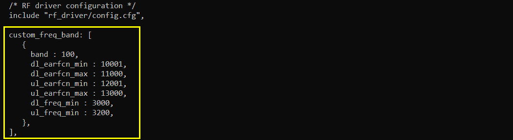
Then I defined my own band and earfcn as below. Here dl_freq_min (absolute frequency in Mhz) is mapped to dl_earfcn_min and ul_freq_min is mapped to ul_earfcn_min. The incremental steps are as defined in 3GPP specification.
I put custom_freq_band right after the RF driver include. It defines band 100. The DL earfcn range is 10001 to 11000 and dl_freq_min is 3000 MHz. The UL earfcn range is 12001 to 13000 and ul_freq_min is 3200 MHz. So dl_earfcn_min 10001 is 3000 MHz and ul_earfcn_min 12001 is 3200 MHz.
Each earfcn step is 100 kHz. With 1000 earfcn values in each range, the band covers 3000 to 3100 MHz in DL and 3200 to 3300 MHz in UL. The band number can be anything from 1 to 256. custom_freq_band can also be an array of objects if you want to define more than one custom band. If you leave out the UL fields, the band is treated as TDD with the same frequencies as the DL.
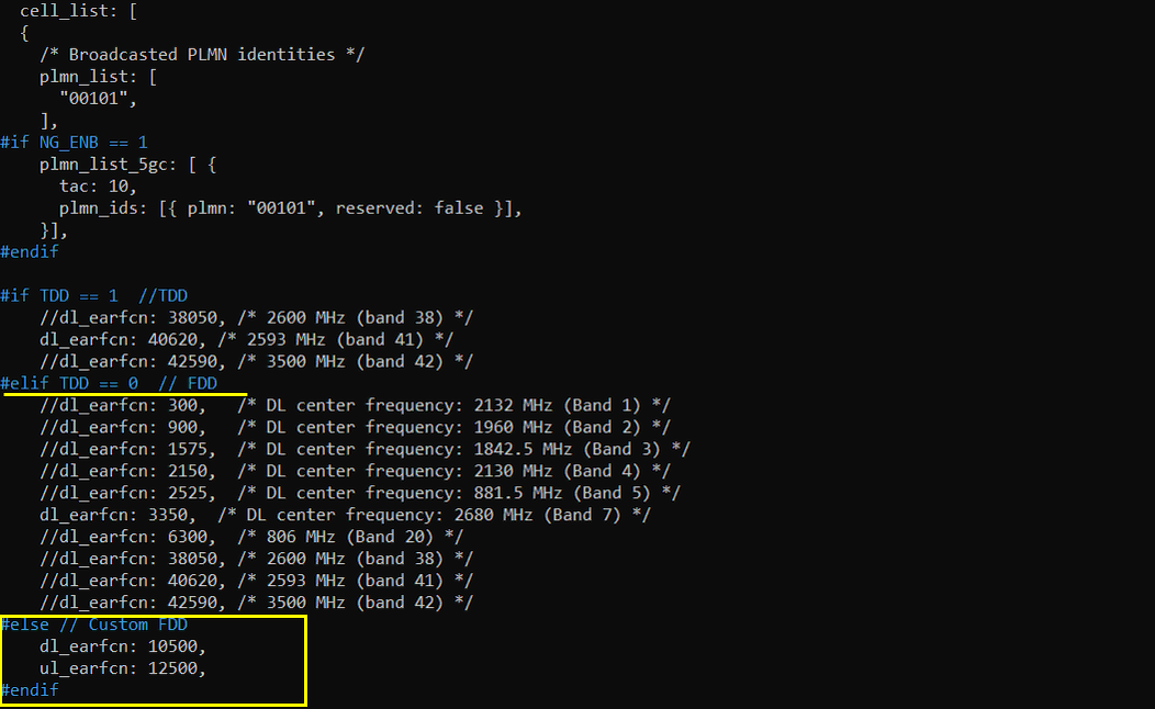
Then I specified an earfcn defined in my own frequecy table. I specified a customer earfcn to dl_earfcn and ul_earfcn.
In cell_list, the earfcn is selected with #if TDD == 1, #elif TDD == 0 and a new #else // Custom FDD branch. Since TDD is 2, only the #else branch is used. It sets dl_earfcn: 10500 and ul_earfcn: 12500. The TDD and standard FDD branches keep their original earfcn lists and are not used in this test.
dl_earfcn 10500 is 499 steps above dl_earfcn_min, so the DL center frequency is 3000 + 49.9 = 3049.9 MHz. In the same way ul_earfcn 12500 gives 3249.9 MHz in UL. ul_earfcn has to be set here. If it is not provided, the eNB uses the default gap of ul_earfcn = dl_earfcn + 18000, and that is outside the custom UL range. To move the cell, pick another dl_earfcn and ul_earfcn inside the ranges defined in custom_freq_band.
Run and Check
I cannot provide any test result with commercial UE since commercial UE would not support the custom band.
Just run the LTE service and go to enb screen mode. You can confirm that the band and frequency from the default print out from (enb) screen. If you run [cell phy] command, you can confirm the ARFCN configuration as well.
At startup the eNB prints RF0 with dl_freq=3049.900 MHz, ul_freq=3249.900 MHz and (band 100). These are the frequencies calculated from the custom band in the configuration. The sample_rate is 5.760 MHz, and dl_ant and ul_ant are both 1.
cell phy shows cell 0x001 as LTE in BAND 100 with BW 5. The DL ARFCN is 10500 with SCS 15 and QAM 256. The UL ARFCN is 12500 with SCS 15 and QAM 64. The SSB columns are empty because this is an LTE cell.

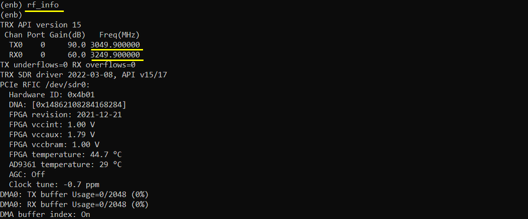
Same as in the default print out of (enb) screen, you can check the frequency with rf_info command.
rf_info shows TX0 at 90.0 dB gain on 3049.900000 MHz and RX0 at 60.0 dB gain on 3249.900000 MHz. So the SDR is really tuned to the custom DL and UL frequencies. TX underflows and RX overflows are both 0.
The rest of the output is the SDR card status, such as the FPGA revision, the temperatures and the DMA buffer usage. It is not related to the custom band.
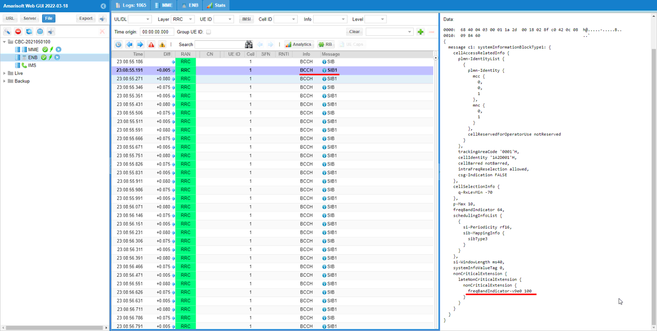
Lastly you can confirm that the band you defined is broadcast in SIB1 message as shown below. Make it sure that freqBandIndicator IE in SIB is set to the custom band that you specified in the configuration file.
In the WebGUI I opened one of the BCCH SIB1 messages. Band 100 is above 64, so it does not go into the freqBandIndicator field itself. That field shows 64. The real band is in freqBandIndicator-v9e0 100, inside nonCriticalExtension, lateNonCriticalExtension and nonCriticalExtension. That is the field to check when you use a band number above 64.
The rest of SIB1 is the usual set. The plmn-Identity is mcc 001 and mnc 01, trackingAreaCode is '0001'H and cellIdentity is '1A2D001'H. p-Max is 10 and q-RxLevMin is -70.