NR SA HO(Handover)
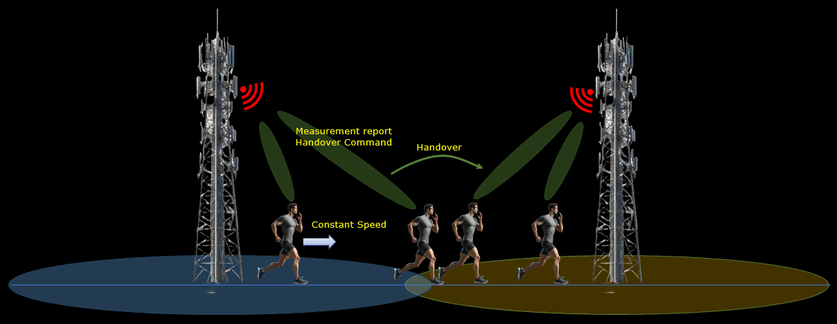
This tutorial shows how to test NR SA to NR SA Handover in Inter Frequency. This tutorial also shows how to configure Measurement Report and how to trigger measurement report. Handover is a procedure of cell change during the connected mode and usually occurs as described below.
Step 1 : Network (gNB) configures measurement request to direct UE to perform the measurement of current cell and neighbouring cells
Step 2 : UE perform the measurement and send the report to the network if the measurement result matches the condition set by the measurement request configuration specified at step 1
Step 3 : Network sends RRC message to force UE to change cell (Handover) to the target cell. In this RRC message, network sends all the necessary low layer information about the target cell (e.g, cell frequency, rach info and other channel information)
In terms of frequencies of current cell and target/destination cell, the handover can be categorized into two types as below
- Intra Frequency Handover : Current Cell and Target Cell frequency is same
- Inter Frequency Handover : Current Cell and Target Cell frequency is different
Table of Contents
- NR SA HO(Handover)
- Introduction
- Summary of the Tutorial
- Test Setup
- Key Configuration Parameters
- Test 1 : SA Inter Frequency Handover - with Cell Power Change
- Test 2 : SA Inter Frequency Handover - PingPong Handover with UE Movement
- Test 3 : SA Inter Frequency Handover - Blind Handover
- Test 4 : SA Inter Frequency Handover - Blind Handover with Contention-Free RACH
- RRC / NAS Signaling
Introduction
Handover procedures constitute a fundamental aspect of 5G NR (New Radio) Standalone (SA) network operations, ensuring seamless connectivity and continuous service as User Equipment (UE) transitions between cells, often across different frequencies. The 5G NR architecture, built upon the principles of service-based architecture and disaggregated network functions, enables intelligent and flexible mobility management through the gNB (next-generation NodeB) and the core network. Inter-frequency handovers, in particular, pose unique challenges and opportunities—requiring the UE to switch between cells operating on different carrier frequencies, which is essential for load balancing, interference management, and optimal spectrum utilization. The process leverages the Measurement Control and Reporting framework, where the gNB specifies measurement objectives and triggering conditions, and the UE conducts and reports on radio conditions for both serving and neighboring cells. Depending on network policy and test scenarios, the handover can be initiated in a measurement-based or blind fashion. This tutorial provides a systematic approach to configuring and testing NR SA to NR SA inter-frequency handovers, highlighting the underlying signaling flows, measurement configuration strategies, and practical test lab considerations. By mastering these procedures, engineers and practitioners can ensure robust mobility management and contribute to the reliability and efficiency of 5G deployments.
-
Technological Context and Background
- 5G NR Standalone Architecture: Operates independently from legacy LTE networks, using gNBs and a 5G Core for all signaling and data traffic.
- Handover Significance: Ensures uninterrupted service by transferring active connections between cells, managing user mobility, and optimizing resource allocation.
- Measurement Procedures: Involves configuring measurement objects, events, and reporting criteria to enable informed cell selection and handover decisions.
- Inter-Frequency Handover: Specifically addresses scenarios where source and target cells operate on different frequencies, requiring additional measurement and configuration procedures.
-
Relevance and Importance of the Tutorial
- Provides hands-on guidance for configuring measurement reports and triggering inter-frequency handovers—critical for real-world network optimization and testing.
- Highlights both measurement-based and blind handover scenarios, reflecting common practices in both operational and lab environments.
- Supports deeper understanding of how 5G NR manages mobility and resource allocation, essential for network engineers, testers, and researchers.
-
Learning Outcomes
- Understand the architecture and signaling flow of NR SA to NR SA inter-frequency handover.
- Acquire the ability to configure measurement reporting on the gNB and UE.
- Identify and execute both measurement-based and blind handover scenarios using test equipment such as the Amarisoft callbox.
- Gain practical skills in verifying, troubleshooting, and optimizing handover performance in lab settings.
-
Prerequisite Knowledge and Skills
- Familiarity with 5G NR radio access network architecture and terminology.
- Understanding of mobility management concepts, including measurement control, reporting, and handover decision processes.
- Experience with radio network testing tools and the configuration of 5G test environments (e.g., Amarisoft callbox or similar platforms).
- Basic knowledge of signaling procedures and network protocols in 5G NR.
Summary of the Tutorial
This tutorial covers a comprehensive set of procedures to test various Standalone (SA) NR Inter Frequency Handover scenarios using Amarisoft gNB and UEsim or commercial UE. The following summarizes the test methodologies, steps, and key procedures described in the tutorial across four main test cases.
-
Test Setup
- Two setups are described: one with UEsim and another with a commercial UE, both interfacing with Amarisoft gNB using the provided SIM card and default configurations.
- Configuration changes can be referenced via the linked Configuration Guide.
-
Key Configuration Parameters
- Important configuration parameters such as ncell_list, meas_config_desc, meas_gap_config, and ho_from_meas are highlighted as essential for handover scenarios and are referenced for further details.
-
Test 1: SA Inter Frequency Handover - with Cell Power Change
-
Configuration Steps:
- Use and modify the provided gnb-sa-ho.cfg (for gNB) and ue-nr-sa-ho.cfg (for UEsim or UE).
- Set up two NR cells with different frequencies, 2x2 MIMO, TDD mode, and 40 MHz bandwidth. Ensure SDR resources are sufficient.
- Add neighbor cell lists to both cell configurations, specifying the other cell as a neighbor with a different frequency.
- Configure meas_config_desc to enable measurement reporting (mainly Event A2 and A3) for handover triggering.
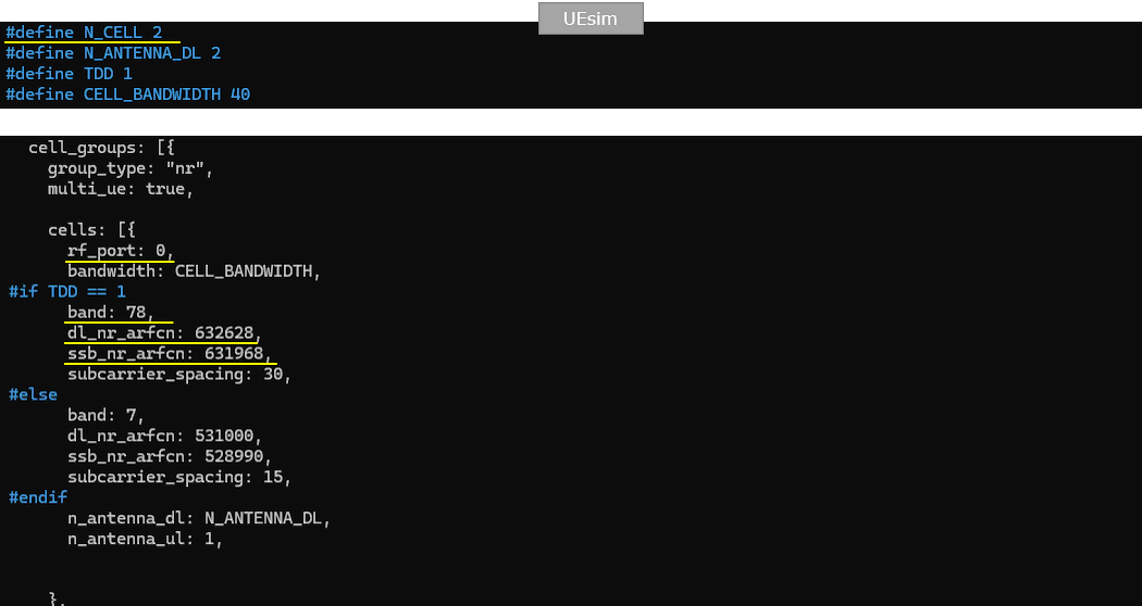
- In UEsim, ensure physical parameters match gNB; set N_CELL=2, N_ANTENNA_DL=2, TDD=1, and CELL_BANDWIDTH=40 for both cells.
-
Test Procedure:
- Start LTE/NR service and verify cell configurations on both gNB and UE/UEsim.
- Adjust cell power using the cell_gain command to trigger measurement reports and handover events without altering SIB broadcast parameters.
- Monitor cell ID changes on the UE/UEsim as an indicator of successful handover.
-
Log Analysis:
- Verify measurement reporting configuration (Events A2/A3) in logs to ensure correct triggering conditions are met.
- Confirm measurement gap enabling and the sequence of measurement and handover events.
-
Configuration Steps:
-
Test 2: SA Inter Frequency Handover - PingPong Handover with UE Movement
-
Configuration Steps:
- Similar to Test 1, with gnb-sa-channel-sim-pingpong-ho.cfg and ue-nr-sa-chan-sim-pingpong-ho.cfg.
- Set UE initial position and channel model (e.g., EPA or AWGN).
-
Test Procedure:
- Start LTE/NR service and verify cell configurations.
- Use a shell script with Amarisoft RemoteAPI (ws.js) to move the UE back and forth between two cells, simulating movement on the x-axis alternately to trigger ping-pong handovers.
- Monitor for cell ID changes and confirm handover execution.
-
Log Analysis:
- Check for alternating cell IDs and PHY scheduling changes as handover indicators.
- Bitrate plots can also show traffic transitions.
- Protocol logs should be used for definitive confirmation of handover events (see Test 1 log analysis for details).
-
Configuration Steps:
-
Test 3: SA Inter Frequency Handover - Blind Handover
-
Configuration Steps:
- Use gnb-sa-ho-blind.cfg for gNB and ue-nr-sa-ho.cfg for UEsim or UE.
- Similar two-cell, two-frequency configuration as previous tests.
- meas_config_desc is commented out to disable measurement-triggered handover, enabling blind handover by gNB command.
-
Test Procedure:
- Start LTE/NR service and verify configurations.
- After the UE is attached and in connected status, execute a blind handover with the following RemoteAPI command:
In intra-cell handover, the ssb_nr_arfcn parameter may be omitted. - Monitor for cell ID changes as confirmation of handover.
-
Log Analysis:
- Check UE capability information, especially for inter frequency handover support.
- Confirm that no measurement configurations are set in RRCReconfiguration messages.
- Verify handover command delivery and subsequent UE RACH procedure on the target cell.
-
Configuration Steps:
-
Test 4: SA Inter Frequency Handover - Blind Handover with Contention-Free RACH
-
Configuration Steps:
- Derived from Test 3, using gnb-sa-ho-blind-cfra.cfg (modified from gnb-sa-ho-blind.cfg).
- The key change is adding reconfig_sync_cfra: true in the configuration to enable contention-free RACH for handover.
-
Test Procedure:
- Start LTE/NR service and verify configurations.
- After UE is in connected status, execute the same RemoteAPI handover command as in Test 3.
- Monitor for cell ID changes to confirm handover execution.
-
Log Analysis:
- Check for presence of cfra configuration in RRC reconfiguration messages, indicating the use of contention-free RACH and specifying the preamble index for the UE.
- Verify that the UE sends PRACH with the specified preamble as indicated in logs.
- SIM Card used in this tutorial is the one delivered with the system as it is.
- If you want to change the configuration, The tutorial Configuration Guide would help
- ncell_list : In this link, you would get the descriptions for all the items listed below
- meas_config_desc : In this link, you would get the descriptions for all the items listed below
- a1_report_type
- a1_rsrp
- a1_hysteresis
- a1_time_to_trigger
- a2_report_type
- a2_hysteresis
- a2_time_to_trigger
- nr_handover
- meas_gap_config
- ho_from_meas
Test Setup
Test setup for this tutorial is as shown below.
< Setup A >

< Setup B >
Key Configuration Parameters
Followings are important configuration parameters for this tutorial. You may click on the items for the descriptions from Amarisoft documents.
Test 1 : SA Inter Frequency Handover - with Cell Power Change
In this test, I will show on a very simple scenario to trigger an handover between two NR SA cells which is triggered by the direct power change of the cell and the corresponding measurement report from UE.
Configuration
I used the gnb-sa-ho.cfg which is copied and modified from gnb-sa.cfg

I also used mme-ims.cfg as it is.

I used the ue-nr-sa-ho.cfg which is copied and modified from ue-nr-sa.cfg
Configure enb-2cell-ho-inter.cfg as below.
This part defines the basic radio configuration used for the NR SA handover test. The exact values can be changed depending on the test purpose, but in this example the callbox is configured for TDD operation with NR_TDD set to 1 and NR_TDD_CONFIG set to 2. The downlink antenna configuration is set to N_ANTENNA_DL 2, which means 2x2 MIMO is used for downlink. The uplink antenna configuration is set to N_ANTENNA_UL 1, so uplink uses a single antenna. The channel bandwidth is set to NR_BANDWIDTH 40, meaning the NR cell bandwidth is 40 MHz. NR_LONG_PUCCH_FORMAT is set to 2, which selects the long PUCCH format used by the UE for uplink control signaling. USE_SRS is set to 0, so periodic SRS is not enabled in this test.

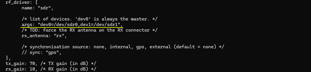
This part defines the SDR device mapping used by the callbox. Before running this handover test, make sure that enough SDR cards are assigned in rf_driver. In this example, the test uses two NR cells with 2x2 MIMO, so two SDR devices are enough. The args field maps dev0 to /dev/sdr0 and dev1 to /dev/sdr1. Here, dev0 is the master device, and dev1 is used as the additional SDR device. The tx_gain is set to 70 dB and rx_gain is set to 10 dB. These gain values define the default transmit and receive gain level before any cell power change is applied during the handover test.
This part defines the first NR cell and adds the second cell as its neighbor cell. The first cell is mapped to rf_port 0, uses cell_id 0x01, and has physical cell ID n_id_cell 500. In this TDD configuration, it uses band 78 with dl_nr_arfcn 632628, which corresponds to 3489.42 MHz, and subcarrier_spacing is set to 30 kHz. Since this test is for inter-frequency handover, the serving cell and target cell should not use the same downlink ARFCN. The ncell_list is added under the first cell configuration, and cell_id 2 is listed as the neighbor cell. This tells the callbox that the second configured NR cell is a handover candidate for the UE currently camped on the first cell.

This part defines the second NR cell and adds the first cell as its neighbor cell. The second cell is mapped to rf_port 1, uses cell_id 0x02, and has physical cell ID n_id_cell 501. In this TDD configuration, it uses band 79 with dl_nr_arfcn 713334 and subcarrier_spacing 30 kHz. The first cell and second cell are configured with different downlink ARFCNs, so this setup can be used for NR SA inter-frequency handover. The ncell_list is added under the second cell configuration, and cell_id 1 is listed as the neighbor cell. This makes the first cell a valid handover target when the UE is currently camped on the second cell.

This part adds the measurement configuration used before triggering the handover. The meas_config_desc section defines which measurement events the UE should report to the gNB. In this example, the UE reports RSRP-based measurements. Event A1 is configured with a1_rsrp -50, hysteresis 10, and time_to_trigger 100. Event A2 is configured with a2_rsrp -60, hysteresis 0, and time_to_trigger 100. These settings allow the gNB to detect when the serving cell condition becomes poor enough to prepare for handover. Under nr_handover, Event A3 is configured with a3_offset 6, hysteresis 0, and time_to_trigger 100. This means the UE can report when the neighbor cell becomes better than the serving cell by the configured offset, and this report can be used by the gNB to trigger NR SA handover. The ssb_rsrq_filter_coeff is set to 3 and ssb_sinr_filter_coeff is set to 5, which control filtering for SSB-based measurement quantities.
NOTE : One important point is the inactivity_timer. In this example, it is set to 10000, but when testing with a commercial UE, it may be safer to increase this value, for example to 600000, which is about 10 minutes. Otherwise, the gNB may release the RRC connection before the UE reaches the handover trigger condition. Another way to avoid early RRC release is to keep IP traffic running, such as continuous ping from the callbox to the UE or active data traffic from the UE. But for a simple handover tutorial, increasing inactivity_timer is usually the easier method.
NOTE : Even if various events are explicitely configured in meas_config_desc, whether they are applied to RRC Reconfiguration or not is determined by various factors. Read carefully on the description of meas_config_desc for NR and meas_config_desc for NR in enb document for the details. For ENDC case, the logic would become even more complicated. So it is strongly suggested to read the entire section carefully before you start testing.Now let's look into UEsim(DUT) configuration. (
NOTE : If you are using commercial UE instead of UEsim (i.e <Setup A>), you can skip this part.This part shows the UEsim configuration for the same NR SA inter-frequency handover test. N_CELL is set to 2 because the test uses two NR cells. N_ANTENNA_DL is set to 2, so the UEsim expects 2x2 MIMO on the downlink side. TDD is set to 1, which means the radio frame structure should match the TDD configuration used in the callbox. CELL_BANDWIDTH is set to 40, so the UEsim bandwidth also matches the 40 MHz NR cell bandwidth configured in the gNB.
The first UEsim cell is configured with rf_port 0. This should match the first cell in the callbox configuration. For the TDD case, band is set to 78, dl_nr_arfcn is set to 632628, ssb_nr_arfcn is set to 631968, and subcarrier_spacing is set to 30 kHz. These values should be aligned with the first gNB cell so that UEsim can correctly search, synchronize, and camp on this cell. The downlink antenna count is set by N_ANTENNA_DL, while n_antenna_ul is set to 1, matching the uplink antenna setting used in this test.
This part configures the second UEsim cell with rf_port 1. This should match the second cell in the callbox configuration. For the TDD case, band is set to 79, dl_nr_arfcn is set to 713334, ssb_nr_arfcn is set to 712608, and subcarrier_spacing is set to 30 kHz. These values should be aligned with the second gNB cell so that UEsim can detect this cell as the inter-frequency handover target. The bandwidth is set by CELL_BANDWIDTH, so it remains 40 MHz. The downlink antenna count is set by N_ANTENNA_DL, which is 2 in this test, and n_antenna_ul is set to 1. This keeps the UEsim physical layer configuration consistent with the second NR cell configured in the callbox.
This part defines the UE profile used by UEsim. In this example, the UE configuration is almost the same as the default ue-nr-sa configuration. The important point is that the IMSI and K value must match the UE subscriber configuration on the gNB or core network side. Here, imsi is set to 001010123456789 and K is set to 00112233445566778899aabbccddeeff. As long as these authentication parameters match, the UE can register normally, and the handover test does not require any special UE capability setting beyond normal NR SA operation. The UE category is set to nr, and as_release is set to 15, meaning this UE is treated as a Release 15 NR UE.
This part is optional and is mainly used to automate the UEsim operation. The sim_events section defines what UEsim should do after startup. At start_time 0, the UE is powered on automatically, so the UE starts the registration procedure as soon as UEsim starts. At start_time 2, UDP traffic is started toward dst_addr 192.168.2.1. One stream uses cbr_recv with payload_len 1472 and bit_rate 200000000, and the other stream uses cbr_send with payload_len 1472 and bit_rate 40000000. This traffic keeps the UE in connected state and helps prevent early RRC release before the handover condition is reached. Finally, at start_time 900, the UE is powered off automatically. This means the whole automated test runs for about 900 seconds unless it is stopped earlier.
Perform the test
Start the service and check the basic NR cell configuration before running the handover test. In this example, the callbox shows two NR cells. Cell 0x001 is configured on band n78 with 40 MHz bandwidth, DL ARFCN 632628, SSB ARFCN 631968, PCI 500, 2 downlink antennas, 1 uplink antenna, and 30 kHz SCS. Cell 0x002 is configured on band n79 with 40 MHz bandwidth, DL ARFCN 713334, SSB ARFCN 712608, PCI 501, 2 downlink antennas, 1 uplink antenna, and 30 kHz SCS. This confirms that both cells are NR cells and that they are using different frequencies, which is required for this inter-frequency handover test. (
NOTE : If you are using UEsim as a DUT instead of mobile phone, make it sure that the cell configuration on UEsim matches the configurations shown here)

Adjust the cell power to create the handover condition. In this test, cell_gain is used instead of tx_gain. This is important because tx_gain can change the broadcast reference cell power information in SIB, and the UE may behave unexpectedly if the SIB information changes during the test. Here, both cells initially show dl_gain 0.0. Then cell_gain 1 -20 is applied to reduce the power of cell 1 by 20 dB. This makes the serving cell weaker and can trigger the first handover toward the other cell. After that, cell_gain 1 -25 reduces the same cell power further, and the cell command confirms that cell 0x001 now has dl_gain -25.0 while cell 0x002 remains at 0.0. Later, cell_gain 1 0 restores the first cell power back to the original level. This creates the opposite radio condition and can trigger the second handover back to the first cell.
If the handover works properly, you should see the serving cell ID change in the UEsim t output. In this trace, the UE first stays on cell 00 with RNTI 4601. After the first handover, the CL field changes from 00 to 01, and the RNTI also changes from 4601 to 4602. This indicates that the UE has moved from the first cell to the second cell. Later, after the radio condition is changed again, the CL field changes back from 01 to 00, and the RNTI changes again from 4602 to 4604. This confirms the second handover back to the original cell. So, for a quick handover check, the most important fields in this output are CL and RNTI. The CL value shows which cell the UE is currently served by, and the RNTI change usually indicates that the UE has completed access on the target cell after handover.
Log Analysis
Sample Log During the initial attach, the callbox sends the measurement configuration to the UE using RRC Reconfiguration. This configuration tells the UE what cells and frequencies should be measured and what reporting rules should be used later for handover. In this log, check measObjectToAddModList, reportConfigToAddModList, and measIdToAddModList. measObjectToAddModList should include the measurement objects for both NR cells. For cell 0x001, the measObjectNR uses ssbFrequency 631968 and freqBandIndicatorNR 78. For cell 0x002, the measObjectNR uses ssbFrequency 712608 and freqBandIndicatorNR 79. These SSB frequencies should match the SSB ARFCN values confirmed earlier in the cell phy output. This confirms that the UE has been instructed to measure both inter-frequency NR cells before the handover is triggered.

Check reportConfigToAddModList and confirm that each report configuration matches the meas_config_desc values in the configuration file. In this example, reportConfigId 1 is for Event A1. It uses rsrp as the trigger quantity, with a1-Threshold rsrp 106, hysteresis 10, and timeToTrigger ms100. This corresponds to the configured a1_report_type rsrp, a1_rsrp -50, a1_hysteresis 10, and a1_time_to_trigger 100.
reportConfigId 2 is for Event A2. It also uses rsrp as the trigger quantity, with a2-Threshold rsrp 96, hysteresis 0, and timeToTrigger ms100. This corresponds to the configured a2_report_type rsrp, a2_rsrp -60, a2_hysteresis 0, and a2_time_to_trigger 100.
These A1 and A2 reports are not the handover trigger itself. They are mainly used to report serving-cell radio condition. The actual handover decision is normally based on the A3 report configuration under nr_handover, so after checking A1 and A2, also check that the next reportConfig item contains Event A3 with the expected offset, hysteresis, and timeToTrigger values.
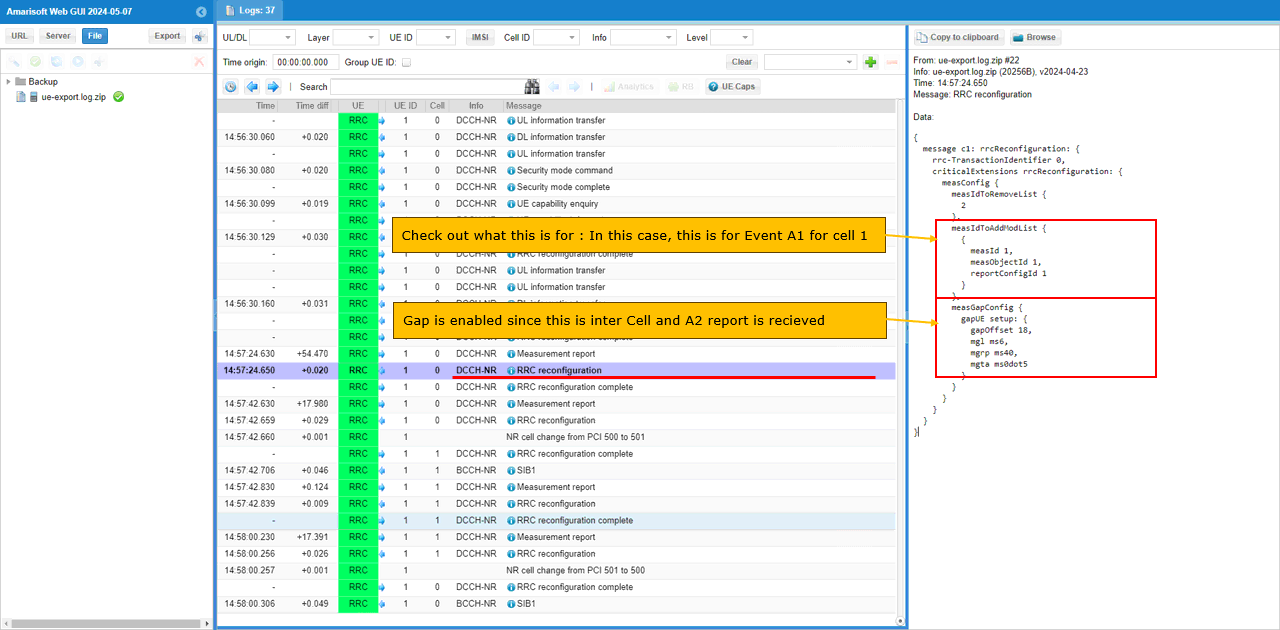
Check measIdToAddModList to see which specific measurement object and report configuration are actually linked together. In this example, measId 2 is configured with measObjectId 1 and reportConfigId 2. This means the UE is ordered to apply reportConfigId 2, which is Event A2, to measObjectId 1, which corresponds to the first cell. So at this stage, the UE is mainly monitoring the serving-cell condition and reporting Event A2 when the serving cell becomes weak enough.
Measurement Gap is not enabled yet in this initial configuration. This can be confirmed from measGapConfig, where gapRelease is shown as NULL. This is expected because the gNB does not need to enable the gap immediately at the beginning. In this Amarisoft flow, the measurement gap is enabled later only when it becomes necessary, such as when the measurement is for inter-frequency or inter-RAT and the proper trigger condition, such as Event A2, has already been reported by the UE. So the key point in this step is to confirm both parts: measIdToAddModList shows what measurement is currently ordered, and measGapConfig shows that measurement gap is still not active at this point.(
NOTE : gNB will enable Measurement Gap only when the measurement is for inter frequency, inter RAT and Event A2 report is recieved. Check out meas_config_desc for further details).
After reducing the serving cell power enough to satisfy the Event A2 condition, the UE sends a Measurement Report. In this log, the reported measId is 2, which matches the earlier measIdToAddModList configuration where measObjectId 1 is linked with reportConfigId 2. This means the report is for Event A2 on cell 1. The report includes the serving cell measurement result, such as physCellId 500, rsrp 93, rsrq 65, and sinr 86. This confirms that the UE detected the serving cell degradation and reported it to the gNB. At this point, the gNB can use this A2 report as the trigger to enable the next measurement step, such as activating measurement gap for inter-frequency neighbor cell measurement.
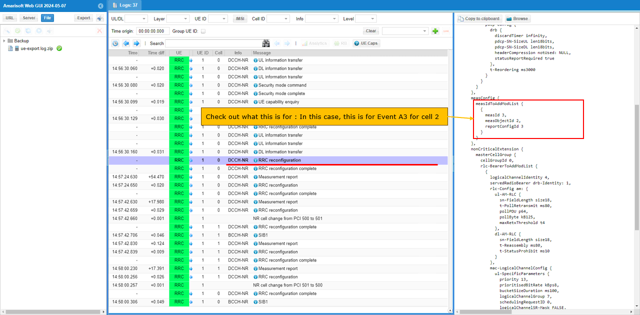
After the UE sends the Event A2 measurement report, the gNB sends another RRC Reconfiguration to configure the next measurement step. In this message, measIdToAddModList shows measId 3, measObjectId 2, and reportConfigId 3. This means the UE is now ordered to apply reportConfigId 3, which is Event A3, to measObjectId 2, which corresponds to cell 2. In this test, cell 2 is the inter-frequency target cell. So this configuration tells the UE to measure the neighbor cell and report when the target cell becomes better than the serving cell by the configured A3 condition. This is the key measurement configuration used to trigger the actual handover from cell 1 to cell 2.
After the UE sends the Event A2 measurement report, the gNB enables the measurement gap and updates the measurement configuration by sending another RRC Reconfiguration. In this message, measIdToRemoveList removes measId 2, which was used for the previous A2 measurement. Then measIdToAddModList adds measId 1 with measObjectId 1 and reportConfigId 1, which means Event A1 is configured again for cell 1. More importantly, measGapConfig is now configured with gapOffset 8, mgl ms6, mgrp ms40, and mgta ms0dot5. This means the UE is given periodic measurement gaps so it can temporarily stop serving-cell reception and measure the inter-frequency target cell. This gap is enabled because the UE already reported A2 and the next step requires inter-frequency neighbor cell measurement for handover.
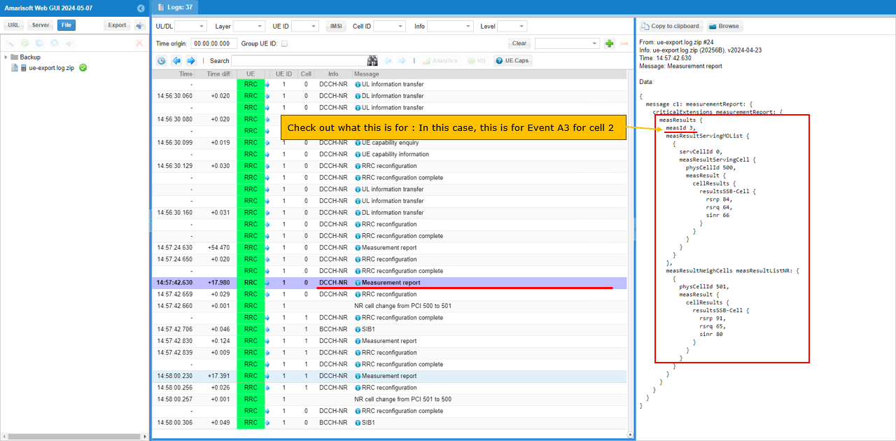
When the cell power is adjusted enough to satisfy the Event A3 condition, the UE sends another Measurement Report. In this log, the reported measId is 3, which matches the earlier configuration where measId 3 was linked to measObjectId 2 and reportConfigId 3. This means this report is for Event A3 on cell 2. The report includes both the serving cell and neighbor cell measurement results. The serving cell is physCellId 500 with rsrp 84, rsrq 64, and sinr 66, while the neighbor cell is physCellId 501 with rsrp 91, rsrq 65, and sinr 80. Since the neighbor cell is now better than the serving cell by the configured A3 condition, this report becomes the trigger for the gNB to start the handover from cell 1 to cell 2.
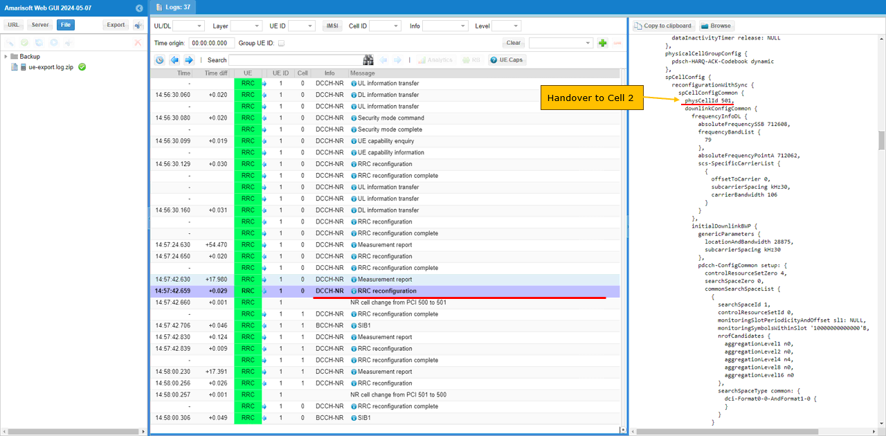
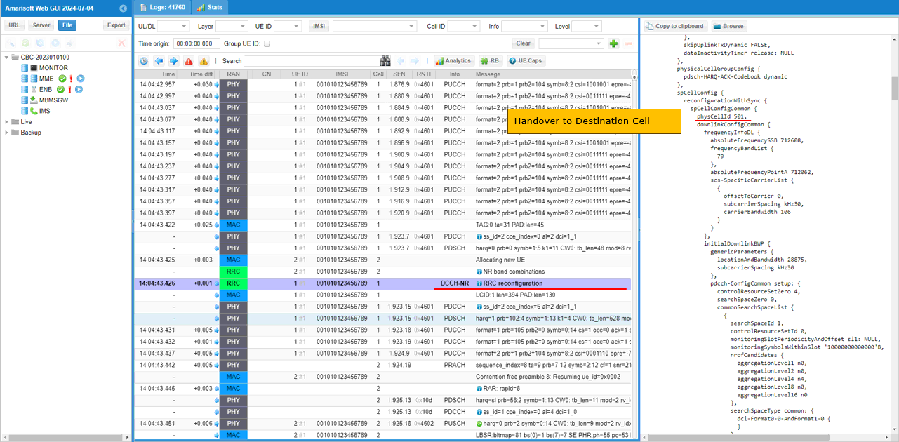
After the Event A3 measurement report is received, the gNB triggers handover to the target cell. In this example, the target physicalCellId is 501, which corresponds to cell 2. The handover command is carried by RRC Reconfiguration, and the message includes reconfigurationWithSync. This is the key indication that the UE is being ordered to move to the target cell. Inside spCellConfigCommon, the target cell information is configured with physCellId 501, absoluteFrequencySSB 712608, frequencyBandList 79, absoluteFrequencyPointA 712062, subcarrierSpacing kHz30, and carrierBandwidth 106. These parameters tell the UE how to synchronize with the target NR cell and continue the connection after handover. The log also shows NR cell change from PCI 500 to 501, confirming that the handover from cell 1 to cell 2 has been triggered.
Test 2 : SA Inter Frequency Handover - PingPong Handover with UE Movement
In this test, I will show on a very simple scenario to trigger an handover between two NR SA cells. In this scenario, UE is first connected to a cell and then moves away from the initial cell and gets closer to other cell which triggers measurement report and lead to handover. Once the UE gets closer to the other cell after the Handover, it changes the direction of the movement 180 degree moving towards the initial cell which lead to another handover. Repetition of this back-and-forth movement between the two cells triggers ping-pong handover.
Configuration
I used the gnb-sa-channel-sim-pingpong-ho.cfg which is copied and modified from gnb-sa.cfg

I also used mme-ims.cfg as it is.
I used the ue-nr-sa-chan-sim-pingpong-ho.cfg which is copied and modified from ue-nr-sa.cfg
Configure gnb-sa-channel-sim-pingpong-ho.cfg as below.
This part defines the basic radio configuration used for Test 2. The values can be changed depending on the test purpose, but in this example the callbox is configured in the same way as the previous handover test. NR_TDD is set to 1, so the cells use TDD operation. NR_TDD_CONFIG is set to 2. N_ANTENNA_DL is set to 2, meaning downlink 2x2 MIMO is used. N_ANTENNA_UL is set to 1, so uplink uses one antenna. NR_BANDWIDTH is set to 40, meaning each NR cell uses 40 MHz bandwidth. NR_LONG_PUCCH_FORMAT is set to 2, and USE_SRS is set to 0, so periodic SRS is not enabled. These parameters should also match the UE or UEsim configuration used in the ping-pong handover test.
This part defines the SDR device mapping for Test 2. Since this ping-pong handover test uses two NR cells with 2x2 MIMO, make sure that enough SDR cards are configured in rf_driver. In this example, dev0 is mapped to /dev/sdr0 and dev1 is mapped to /dev/sdr1. dev0 is always the master device, and dev1 is used for the second RF path. The tx_gain is set to 70 dB and rx_gain is set to 10 dB. These values define the base RF gain setting for the test, while the actual ping-pong handover condition will be created later by changing the simulated UE movement and the relative radio condition between the two cells.
This part defines the first NR cell for Test 2 and adds the second cell as its neighbor cell. The first cell uses rf_port 0, cell_id 0x01, and physical cell ID n_id_cell 500. In the TDD case, it is configured on band 78 with dl_nr_arfcn 632628, corresponding to 3489.42 MHz, and subcarrier_spacing 30 kHz. The ncell_list includes cell_id 2, so the second cell is configured as the neighbor cell and can be used as the handover target. Since this is an inter-frequency handover test, the serving cell and the target cell should use different DL ARFCNs. This allows the UE to move from the first frequency to the second frequency when the measurement condition is satisfied.
This part defines the second NR cell for Test 2 and adds the first cell as its neighbor cell. The second cell uses rf_port 1, cell_id 0x02, and physical cell ID n_id_cell 501. In the TDD case, it is configured on band 79 with dl_nr_arfcn 713334 and subcarrier_spacing 30 kHz. The ncell_list includes cell_id 1, so the first cell is configured as the neighbor cell and can be used as the handover target when the UE moves back toward the original cell. Since this ping-pong handover test repeats handover in both directions, neighbor cell configuration should be added on both cells. Cell 1 should know cell 2 as a neighbor, and cell 2 should know cell 1 as a neighbor. This allows handover from cell 1 to cell 2 and then back from cell 2 to cell 1.
This part adds the measurement criteria used for the ping-pong handover test. The meas_config_desc section defines the RSRP-based measurement reporting rules. Event A1 is configured with a1_rsrp -50, hysteresis 10, and time_to_trigger 100. Event A2 is configured with a2_rsrp -60, hysteresis 0, and time_to_trigger 100. These reports are used to detect the serving-cell radio condition before enabling the next measurement step. Under nr_handover, Event A3 is configured with a3_offset 6, hysteresis 0, and time_to_trigger 100. This is the main handover condition, meaning the UE reports when the neighbor cell becomes better than the serving cell by the configured offset. For ping-pong handover, this same logic is used in both directions as the UE moves toward the second cell and then moves back toward the first cell.
The meas_gap_config is also configured with pattern_id 0. This allows the gNB to enable measurement gaps when inter-frequency measurement is needed. Since the two cells are on different frequencies, the UE may need measurement gaps to measure the target cell properly. Also, when using a commercial UE, it is better to increase inactivity_timer to a large value, for example 600000, which is about 10 minutes. Otherwise, the RRC connection may be released before the movement reaches the handover trigger point. Keeping IP traffic active can also prevent early RRC release, but increasing inactivity_timer is usually simpler for this tutorial.
NOTE : Even if various events are explicitely configured in meas_config_desc, whether they are applied to RRC Reconfiguration or not is determined by various factors. Read carefully on the description of meas_config_desc for NR in enb document for the details. For ENDC case, the logic would become even more complicated. So it is strongly suggested to read the entire section carefully before you start testing.Now let's look into UEsim(DUT) configuration. (
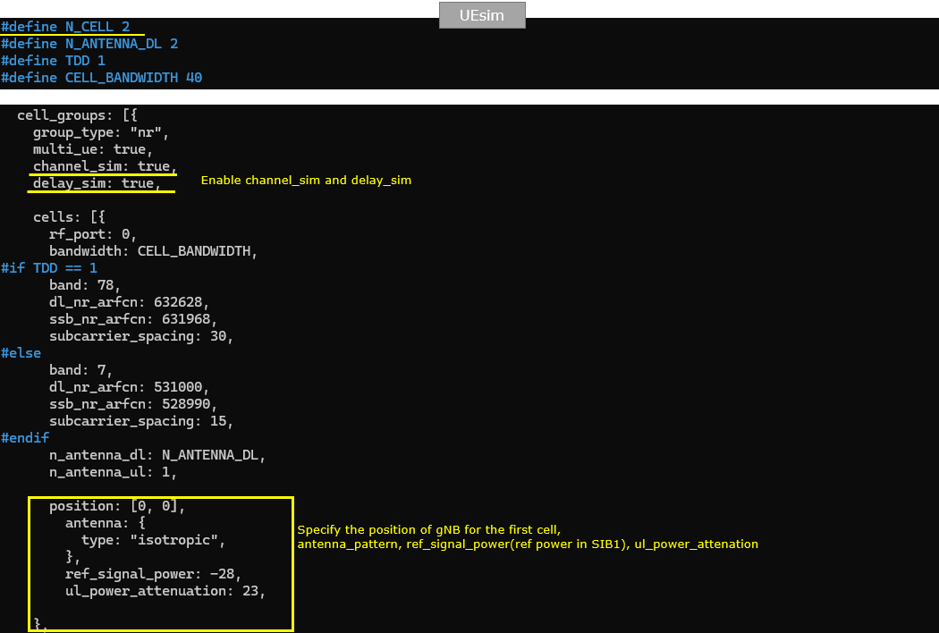
NOTE : If you are using commercial UE instead of UEsim (i.e <Setup A>), you can skip this part.This part shows the UEsim configuration for Test 2. N_CELL is set to 2 because the ping-pong handover test uses two NR cells. N_ANTENNA_DL is set to 2 for 2x2 MIMO, TDD is set to 1 for TDD operation, and CELL_BANDWIDTH is set to 40. These values should match the callbox configuration so that UEsim and gNB use the same basic radio setup.
For this movement-based test, channel_sim and delay_sim are enabled. This is important because the handover is not triggered by manually changing cell power. Instead, UEsim simulates the UE position and movement, and the received signal condition changes according to the simulated distance from each cell. The first cell is configured on rf_port 0 with band 78, dl_nr_arfcn 632628, ssb_nr_arfcn 631968, and subcarrier_spacing 30 kHz. This matches the first cell in the callbox configuration.
The position value is set to [0, 0], which defines the simulated location of the first gNB cell. The antenna type is isotropic, so the signal is modeled without a directional antenna pattern. ref_signal_power is set to -28, which represents the reference signal power used in the simulation, and ul_power_attenuation is set to 23, which controls uplink attenuation. These parameters are used by the channel simulator to calculate the radio condition seen by the moving UE.
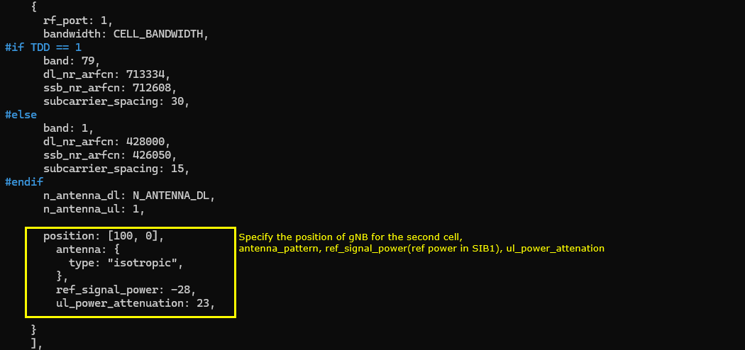
The second UEsim cell is configured with rf_port 1, and it should match the second NR cell in the callbox configuration. In the TDD case, this cell uses band 79, dl_nr_arfcn 713334, ssb_nr_arfcn 712608, and subcarrier_spacing 30 kHz. The bandwidth is set by CELL_BANDWIDTH, so it remains 40 MHz, and the downlink antenna count follows N_ANTENNA_DL, which is 2 in this test.
For the movement simulation, the second gNB position is set to [100, 0]. This means the second cell is located 100 meters away from the first cell, which was configured at [0, 0]. With channel_sim and delay_sim enabled, UEsim uses these positions to calculate the relative radio condition as the UE moves between the two cells. The antenna type is isotropic, so no directional antenna pattern is applied. ref_signal_power is set to -28, the same as the first cell, and ul_power_attenuation is set to 23. Since both cells use the same reference power and attenuation values, the handover behavior mainly depends on the simulated UE position and movement between the two gNB locations.
This part defines the UE-side position and channel model used for the movement-based ping-pong handover test. The IMSI and K values are the normal UE authentication parameters and should match the subscriber configuration. The handover-specific part is the position and channel section. In this example, the initial UE position is set to [10, 0], so the UE starts closer to the first gNB at [0, 0] than to the second gNB at [100, 0]. The channel model type is set to epa, and freq_doppler is set to 50. This creates a fading channel condition for the simulated UE movement. The mimo_correlation is set to low, which controls the correlation assumption between MIMO antenna paths. For this test, EPA is used, but another channel model such as awgn can also be used depending on how simple or realistic you want the simulation to be. The position shown here is only the initial UE position. During the test, this position can be changed through RemoteAPI to emulate UE movement between the two cells.
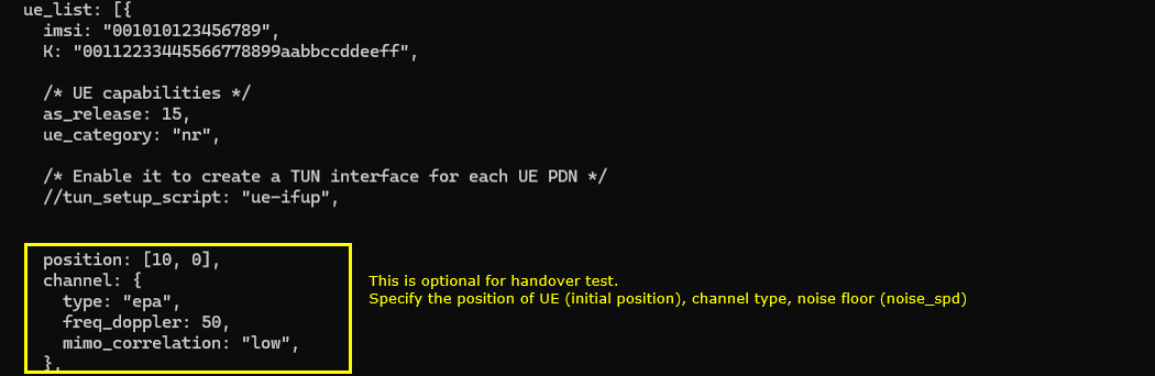
This part is optional and is mainly used to automate the UEsim operation for the ping-pong handover test. The sim_events section automatically powers on the UE at start_time 0, so the UE starts registration as soon as UEsim starts. Then, at start_time 2, UDP traffic is started toward dst_addr 192.168.2.1. One traffic flow uses cbr_recv with payload_len 1472 and bit_rate 200000000, and the other uses cbr_send with payload_len 1472 and bit_rate 40000000. This continuous traffic helps keep the UE in RRC connected state and prevents early RRC release before the movement-based handover condition is reached. Finally, at start_time 900, the UE is powered off automatically. This makes the test run automatically for about 900 seconds, while the UE position can be changed during the test through RemoteAPI to create repeated handover between the two cells.
Perform the test
Start the service and check the basic NR cell configuration before running the ping-pong handover test. In this example, the callbox shows two NR cells. Cell 0x001 is NR band n78 with 40 MHz bandwidth, DL ARFCN 632628, SSB ARFCN 631968, PCI 500, 2 downlink antennas, 1 uplink antenna, and 30 kHz SCS. Cell 0x002 is NR band n79 with 40 MHz bandwidth, DL ARFCN 713334, SSB ARFCN 712608, PCI 501, 2 downlink antennas, 1 uplink antenna, and 30 kHz SCS. The cell command also confirms that both cells are active with dl_gain 0.0 at the beginning. This is the baseline condition before UE movement is simulated. If UEsim is used as the DUT, the UEsim configuration should match these values, especially band, DL ARFCN, SSB ARFCN, bandwidth, antenna count, and SCS.
In this step, the handover is triggered by moving the simulated UE instead of manually changing the cell power. The UE starts from the initial position near the first cell, then RemoteAPI is used to move the UE toward the second cell. As the UE moves farther away from the first cell and closer to the second cell, the serving-cell RSRP becomes weaker and the neighbor-cell RSRP becomes stronger. This eventually triggers the measurement report and allows the gNB to initiate handover. In this example, a simple shell script is used to automate the movement. First, the UE position is initialized to [10, 0] with speed 0. Then the UE moves in the positive x direction with speed 7.2 for 40 seconds. After that, the direction is changed to -180 degrees, so the UE moves back toward the first cell for another 40 seconds. This loop is repeated by num_iter, so the UE moves back and forth between the two cells and can generate repeated handover events. At the end of the script, the UE is moved back to [10, 0] and stopped by setting speed to 0.
#!/bin/bash
num_iter=2
#set initial position
./ws.js ue '{"message" : "ue_move", "ue_id" : 1, "position" : [10,0], "speed" : 0}'
for ((i=0; i<$num_iter; i++)); do
# move to the right on x axis at a 2 m/s
./ws.js ue '{"message" : "ue_move", "ue_id" : 1, "speed" : 7.2, "direction" : 0}'
sleep 40
# move to the left on x axis at 2 m/s
./ws.js ue '{"message" : "ue_move", "ue_id" : 1, "speed" : 7.2, "direction" : -180}'
sleep 40
done
#stop it somewhere
./ws.js ue '{"message" : "ue_move", "ue_id" : 1, "position" : [10,0], "speed" : 0}'
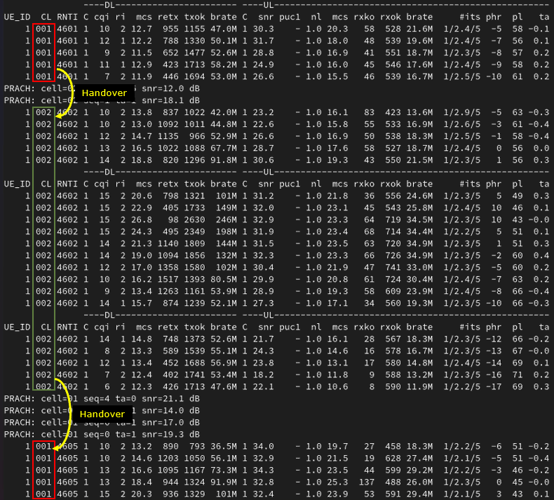
If the handover works properly, you should see the serving cell ID change in the UEsim t output. In this trace, the UE first stays on cell 001 with RNTI 4601. After the first handover, the UE performs PRACH on the target cell and the CL field changes from 001 to 002. The RNTI also changes from 4601 to 4602, which indicates that the UE has completed access on the new serving cell. Later, when the simulated UE moves back toward the original cell, another PRACH is triggered and the CL field changes from 002 back to 001. The RNTI changes again from 4602 to 4605. This confirms the ping-pong handover behavior between the two cells. For a quick check, monitor the CL field, RNTI value, and PRACH lines. CL shows the current serving cell, RNTI change shows that the UE has been reconfigured on the target cell, and PRACH indicates that the UE is accessing the target cell during handover.
Log Analysis
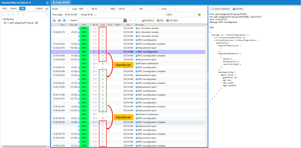
At the highest level, you can first check whether the Cell column changes back and forth between the two cells. In this gNB log, the UE initially stays on cell 1. After the measurement report and RRC reconfiguration, the Cell column changes from 1 to 2, which indicates that the UE has moved to the second cell. Later, after another measurement report and RRC reconfiguration, the Cell column changes from 2 back to 1. This repeated change between cell 1 and cell 2 is a good first-level indication of ping-pong handover.
However, the Cell change alone should not be treated as the final proof of handover, because a cell change may happen for other reasons as well. To confirm that this is really handover, check the detailed RRC messages around the cell change point. You should see a measurement report from the UE, followed by RRC Reconfiguration from the gNB, RRC Reconfiguration Complete from the UE, and then the serving Cell value changing to the target cell. In the highlighted example, the selected RRC Reconfiguration also shows measurement configuration updates such as measIdToRemoveList, measIdToAddModList, and measGapConfig. This means the gNB is actively controlling the measurement and handover preparation process, not just showing a simple display-side cell change.
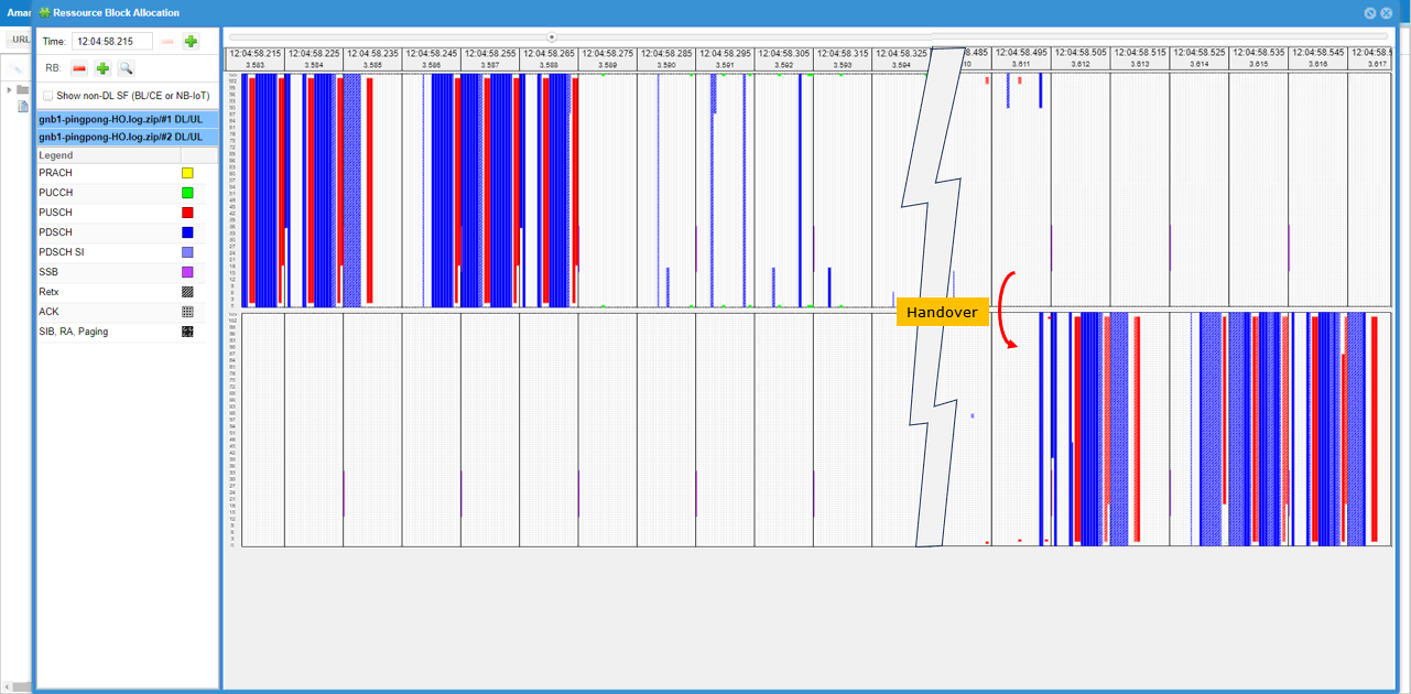
You can also use the PHY resource block map as another visual indicator of handover. In this view, the scheduler activity is shown separately for each cell. Before handover, most of the active PDSCH and PUSCH scheduling is visible on the first cell side. Around the handover point, there is a short transition period with reduced or interrupted scheduling while the UE performs the handover procedure. After the handover completes, the active scheduling appears on the other cell side. This means the UE traffic is no longer scheduled by the previous serving cell and is now scheduled by the target cell. So, together with the RRC log and the Cell column change, the RB map gives a useful PHY-level confirmation that the serving cell has changed during handover.
Another way to confirm the traffic movement between the two cells is to check the Bitrate plot. In this view, the traffic curve changes according to which cell is currently serving the UE. Before handover, the traffic is associated with cell 1. When the UE moves toward the second cell and handover is completed, the bitrate activity shifts to cell 2. Later, when the UE moves back toward the first cell, the bitrate activity shifts back to cell 1 again. This does not show the RRC handover procedure directly, but it is a useful traffic-level confirmation that the active data path follows the serving cell change. So, together with the RRC log, Cell column change, PRACH activity, and RB map, the Bitrate plot gives another practical indication that ping-pong handover is occurring between the two NR SA cells.
NOTE : The most obvious indicator of handover should be confirmed by protocol log. The protocol log analysis for this test is same as in Test 1. Check out the log analysis of Test 1 for the details.Test 3 : SA Inter Frequency Handover - Blind Handover
In this test, I will show on a very simple scenario to trigger an handover between two NR SA cells which is triggered by the direct power change of the cell and the corresponding measurement report from UE.
Configuration
I used the gnb-sa-ho-blind.cfg which is copied and modified from gnb-sa.cfg

I also used mme-ims.cfg as it is.
I used the ue-nr-sa-ho.cfg which is copied and modified from ue-nr-sa.cfg
Configure gnb-sa-ho-blind.cfg as below.
This part defines the basic radio configuration used for Test 3, the blind handover test. The values can be changed depending on the test purpose, but in this example the callbox uses the same basic setup as the previous inter-frequency handover tests. NR_TDD is set to 1, so the cells operate in TDD mode. NR_TDD_CONFIG is set to 2. N_ANTENNA_DL is set to 2, meaning downlink 2x2 MIMO is used, and N_ANTENNA_UL is set to 1, meaning uplink uses one antenna. NR_BANDWIDTH is set to 40, so each NR cell uses 40 MHz bandwidth. NR_LONG_PUCCH_FORMAT is set to 2, and USE_SRS is set to 0, so periodic SRS is not enabled in this test. These parameters define the common physical layer setup before configuring the two NR cells used for blind handover.
This part defines the SDR device mapping for Test 3, the blind handover test. Since this setup uses two NR cells with 2x2 MIMO, make sure that enough SDR cards are assigned in rf_driver. In this example, dev0 is mapped to /dev/sdr0 and dev1 is mapped to /dev/sdr1, which is enough for the two-cell test. dev0 is always the master device, and dev1 is used as the second SDR device. The rx_antenna is set to rx, and the sync source is left as the default setting. The tx_gain is set to 70 dB and rx_gain is set to 10 dB. These values provide the base RF gain setting before running the blind handover procedure.
This part defines the first NR cell for Test 3 and adds the second cell as its neighbor cell. The first cell uses rf_port 0, cell_id 0x01, and physical cell ID n_id_cell 500. In the TDD case, it is configured on band 78 with dl_nr_arfcn 632628, which corresponds to 3489.42 MHz, and subcarrier_spacing 30 kHz. The ncell_list includes cell_id 2, so the second cell is known as a neighbor cell and can be used as the target cell. Even though this test is for blind handover, the neighbor cell relation should still be configured so that the gNB knows the target cell information. Since this is inter-frequency handover, the serving cell and target cell use different DL ARFCNs.
This part defines the second NR cell for Test 3 and adds the first cell as its neighbor cell. The second cell uses rf_port 1, cell_id 0x02, and physical cell ID n_id_cell 501. In the TDD case, it is configured on band 79 with dl_nr_arfcn 713334 and subcarrier_spacing 30 kHz. The ncell_list includes cell_id 1, so the first cell is also known as a neighbor cell and can be used as the target cell when handover is performed in the reverse direction.
For blind handover, this neighbor relation is still important because the gNB needs to know the target cell configuration before sending the handover command. Since this is an inter-frequency handover test, the first cell and second cell use different DL ARFCNs. This allows the UE to be moved from cell 2 back to cell 1, or from cell 1 to cell 2, depending on which blind handover command is triggered during the test.
This part is different from the previous measurement-based handover tests. Since Test 3 is for blind handover, the handover is triggered directly by the gNB without waiting for a Measurement Report from the UE. For that reason, the meas_config_desc section is commented out. This means the UE is not explicitly configured with A1, A2, or A3 measurement reporting rules for triggering the handover.
The inactivity_timer is set to 600000, which is about 10 minutes. This is useful especially when testing with a commercial UE. If the inactivity timer is too short, the gNB may release the RRC connection before you manually trigger the blind handover. You can also keep the UE connected by generating IP traffic, such as continuous ping from the callbox to the UE or active traffic from the UE side. But for this kind of tutorial test, increasing inactivity_timer is usually the simpler method.

Now let's look into UEsim(DUT) configuration. (
NOTE : If you are using commercial UE instead of UEsim (i.e <Setup A>), you can skip this part.If you are using a commercial UE instead of UEsim, this part can be skipped. In this example, N_CELL is set to 2 because the test uses two NR cells. N_ANTENNA_DL is set to 2 for 2x2 MIMO, TDD is set to 1 for TDD operation, and CELL_BANDWIDTH is set to 40. These values should match the gNB callbox configuration.
The first UEsim cell is configured with rf_port 0, which should match the first gNB cell. In the TDD case, it uses band 78, dl_nr_arfcn 632628, ssb_nr_arfcn 631968, and subcarrier_spacing 30 kHz. These parameters should be aligned with the first cell on the callbox so that UEsim can properly search and camp on the source cell before the blind handover is triggered. The downlink antenna count follows N_ANTENNA_DL, and n_antenna_ul is set to 1, matching the uplink antenna setting used in this test.
The second UEsim cell is configured with rf_port 1, and this should match the second NR cell in the gNB callbox configuration. In the TDD case, it uses band 79, dl_nr_arfcn 713334, ssb_nr_arfcn 712608, and subcarrier_spacing 30 kHz. The bandwidth is set by CELL_BANDWIDTH, so it remains 40 MHz. The downlink antenna count follows N_ANTENNA_DL, which is 2 in this test, and n_antenna_ul is set to 1. These values should be aligned with the second gNB cell so that UEsim can correctly synchronize to the target cell when the blind handover command is triggered.
The UE profile is the same as the default ue-nr-sa configuration. For this blind handover test, there is no special UE-side handover parameter required in this section. The important point is that imsi and K must match the subscriber configuration on the gNB or core network side. In this example, imsi is set to 001010123456789 and K is set to 00112233445566778899aabbccddeeff. As long as these authentication values match, the UE can register normally before the blind handover is triggered. The UE capability is set with as_release 15 and ue_category nr, so the UE is treated as a Release 15 NR UE.
Perform the test
Start the service and check the basic cell configuration before triggering blind handover. In this example, both configured cells are NR cells. Cell 0x001 is configured on band n78 with 40 MHz bandwidth, DL ARFCN 632628, SSB ARFCN 631968, PCI 500, 2 downlink antennas, 1 uplink antenna, and 30 kHz SCS. Cell 0x002 is configured on band n79 with 40 MHz bandwidth, DL ARFCN 713334, SSB ARFCN 712608, PCI 501, 2 downlink antennas, 1 uplink antenna, and 30 kHz SCS. The cell command also confirms that both cells are active and the initial dl_gain is 0.0 for both cells. Since this is an inter-frequency blind handover test, the two cells should use different frequencies, but the UE or UEsim configuration should still match the cell parameters shown here.
The power on UE and wait until the initial attach is complete and the call is in connected status.
Once the UE is connected, go to the /root/enb directory and trigger blind handover using the RemoteAPI command. In this example, the command sends a handover request for ran_ue_id 1 toward the target PCI 501 with ssb_nr_arfcn 712608. PCI 501 corresponds to the second cell, and ssb_nr_arfcn 712608 is the SSB frequency of the target inter-frequency cell. For intra-frequency handover, specifying the target PCI may be enough. But for inter-frequency handover, the target SSB ARFCN should also be specified so that the gNB can generate the proper handover command toward the correct target frequency. The WebSocket response shows Message received, which means the callbox accepted the RemoteAPI handover command. (
NOTE : In case of intra cell Handover, ./ws.js enb '{"message":"handover","ran_ue_id":1,"pci":501 }'would be enough, but in case of inter cell Handover as in this test case, you need to specify the target cell ssb_nr_arfcn)[root@CBU-SOPHIA-TEST enb]# ./ws.js enb '{"message":"handover","ran_ue_id":1,"pci":501,"ssb_nr_arfcn":712608 }'
WebSocket remote API tool version 2024-06-06, Copyright (C) 2012-2024 Amarisoft
[0.003] ### Connected to 127.0.0.1:9001
[0.004] ### Ready: name=ENB, type=ENB, version=2024-03-15
[0.031] <== Send message handover id#1
[0.042] ==> Message received
{
"message": "handover",
"message_id": "id#1",
"time": 144.224,
"utc": 1718117032.955
}
If the blind handover works properly, you should see the serving cell ID change in the t output. In this trace, the UE is first connected to cell 001 with RNTI 4601. After the RemoteAPI handover command is sent, PRACH is performed on the target cell, shown as PRACH: cell=002. Then the CL field changes from 001 to 002, and the RNTI changes from 4601 to 4602. This confirms that the UE moved from the source cell to the target cell. Since this is blind handover, the important point is that the cell change happens after the gNB-triggered handover command, not after a UE Measurement Report. For a quick check, monitor the PRACH line, CL field, and RNTI value.
Log Analysis
Before checking the blind handover command itself, it is good to confirm the UE capability procedure first. In this test, the gNB sends UE Capability Enquiry after the UE completes the initial RRC connection and security procedure. The important point is that the requested capability includes NR band 78 and band 79. These are the two bands used in this inter-frequency blind handover test. Band 78 is used by the first cell, and band 79 is used by the second cell. This confirms that the gNB is asking the UE whether it supports the source and target NR bands before proceeding with the later RRC reconfiguration and handover procedure. If the UE does not report proper capability for the target band, the blind handover may fail even if the target cell configuration itself is correct.
In UE Capability Information, one important point is to confirm whether the UE supports inter-frequency handover. This can be checked under measAndMobParameters. In this example, measAndMobParametersFRX-Diff includes handoverInterF supported. This means the UE declares support for inter-frequency handover in NR. Since this test moves the UE between band n78 and band n79, this capability is important. If handoverInterF is not supported, the gNB may not be able to perform the blind inter-frequency handover successfully, even though both cells are configured correctly. So before analyzing the actual handover command, first confirm that the UE capability includes the required inter-frequency mobility support.
Since meas_config_desc is commented out in the configuration file, the initial RRC Reconfiguration does not include measurement-related configuration. In this log, the RRC Reconfiguration contains normal radio bearer and cell group configuration, such as spCellConfigDedicated, pdsch-Config, uplinkConfig, pusch-Config, and pdsch-ServingCellConfig. But there is no measConfig, no measObjectToAddModList, no reportConfigToAddModList, and no measIdToAddModList.
This is expected for the blind handover test. The UE is not being prepared to send Event A1, A2, or A3 measurement reports. Instead, the handover will be triggered directly by the gNB through the RemoteAPI command. So this log is useful because it confirms that the test is really running as blind handover, not measurement-based handover.
Once the RemoteAPI handover command is sent and accepted, the gNB sends the handover command to the UE using RRC Reconfiguration. In this example, the command is triggered with ran_ue_id 1, target pci 501, and ssb_nr_arfcn 712608. After that, the RRC Reconfiguration includes reconfigurationWithSync, which is the key indication that this message is not just a normal configuration update but a handover command.
Inside spCellConfigCommon, the target cell is configured with physCellId 501. This corresponds to the destination cell. The message also includes the target frequency information such as absoluteFrequencySSB 712608, frequencyBandList 79, absoluteFrequencyPointA 712062, subcarrierSpacing kHz30, and carrierBandwidth 106. These parameters tell the UE how to synchronize to the target inter-frequency cell. Since this is blind handover, this command is sent directly after the RemoteAPI trigger, without relying on a UE measurement report.
If the RRC Reconfiguration carrying the handover command is received and processed correctly, the UE starts random access on the target cell. In this log, the UE first receives the handover command, then the PHY log shows PRACH on cell 2. This indicates that the UE is trying to access the destination cell after applying reconfigurationWithSync. After PRACH, the target cell allocates a new UE context, the UE receives RAR, and the MAC/RRC procedure continues on the target cell. This is an important confirmation point for blind handover. The handover command alone only shows that the gNB ordered the UE to move, but PRACH on the target cell shows that the UE actually synchronized to the destination cell and started the access procedure there.
Test 4 : SA Inter Frequency Handover - Blind Handover with Contention-Free RACH
The purpose of this tutorial is to show how to configure and test contention free rach procedure in a simplest manner. In Amarisoft gNB, contention-free rach can be triggered mainly in two scenario. The first scenario is with NSA setup (i.e, RACH to add NR addition) and NR-to-NR handover (i.e, RACH to handover to the destination cell). In this tutorial, contention-free rach procedure in NR-to-NR handover scenario will be demonstrated.
Configuration
NOTE : For this test, there is only very minor modification from the configuration of the previous test. I would just shows only the configuration that differs from the previous test configuration here. For the detailed description of the configuration, refer to the configuration of previous test.I used the gnb-sa-ho-blind-cfra.cfg which is copied and modified from gnb-sa-ho-blind.cfg . Ony this enb configuration file has been modified from previous test. mme, ims and uesim configuration remain unchanged.

Configure gnb-sa-ho-blind-cfra.cfg as below.
This is the only additional configuration compared to the previous blind handover test. The parameter reconfig_sync_cfra is set to true under nr_cell_default, so the same setting is applied to all configured NR cells. This enables contention-free RACH for the reconfigurationWithSync procedure used during handover. With this setting, when the gNB sends the blind handover command, it can include dedicated random access information for the target cell. Then the UE can perform RACH using the assigned contention-free resource instead of selecting a normal contention-based preamble.
The remaining prach configuration defines the normal PRACH resources used by the cell. In this example, the PRACH configuration includes prach_config_index, msg1_subcarrier_spacing 30 kHz, msg1_fdm 1, zero_correlation_zone_config 15, preamble_received_target_power -110 dBm, preamble_trans_max 7, power_ramping_step 4 dB, and ra_response_window 20 slots for TDD. These values define the PRACH opportunity and RACH behavior on the cell. The key point for this test is reconfig_sync_cfra: true, because this is what changes the handover RACH procedure from contention-based RACH to contention-free RACH.
Perform the test
Start the service and check the basic cell configuration before triggering the contention-free RACH blind handover test. In this example, both configured cells are NR cells. Cell 0x001 is configured on band n78 with 40 MHz bandwidth, DL ARFCN 632628, SSB ARFCN 631968, PCI 500, 2 downlink antennas, 1 uplink antenna, and 30 kHz SCS. Cell 0x002 is configured on band n79 with 40 MHz bandwidth, DL ARFCN 713334, SSB ARFCN 712608, PCI 501, 2 downlink antennas, 1 uplink antenna, and 30 kHz SCS. The cell command also confirms that both cells are active and the initial dl_gain is 0.0 for both cells. This baseline check is the same as the previous blind handover test, but in this test the later handover RACH procedure should use contention-free RACH because reconfig_sync_cfra is enabled in the cell configuration. (
NOTE : If you are using UEsim as a DUT instead of mobile phone, make it sure that the cell configuration on UEsim matches the configurations shown here)The power on UE and wait until the initial attach is complete and the call is in connected status.
Then go to the /root/enb directory and send the RemoteAPI handover command. In this example, the command requests handover for ran_ue_id 1 toward target PCI 501 with ssb_nr_arfcn 712608. PCI 501 is the destination cell, and 712608 is the SSB ARFCN of the target inter-frequency cell. For intra-frequency handover, specifying only the target PCI may be enough. But for inter-frequency handover, the target SSB ARFCN should also be included so that the gNB can build the handover command for the correct target frequency. The WebSocket output shows Message received, which means the callbox accepted the handover request. Since reconfig_sync_cfra is enabled in this test, the following handover procedure should allocate contention-free RACH information to the UE. (
NOTE : In case of intra cell Handover, ./ws.js enb '{"message":"handover","ran_ue_id":1,"pci":501 }'would be enough, but in case of inter cell Handover as in this test case, you need to specify the target cell ssb_nr_arfcn)[root@CBU-SOPHIA-TEST enb]# ./ws.js enb '{"message":"handover","ran_ue_id":1,"pci":501,"ssb_nr_arfcn":712608 }'
WebSocket remote API tool version 2024-06-06, Copyright (C) 2012-2024 Amarisoft
[0.003] ### Connected to 127.0.0.1:9001
[0.004] ### Ready: name=ENB, type=ENB, version=2024-03-15
[0.031] <== Send message handover id#1
[0.042] ==> Message received
{
"message": "handover",
"message_id": "id#1",
"time": 144.224,
"utc": 1718117032.955
}
If the handover works properly, you should see the serving cell ID change in the t output. In this trace, the UE is initially connected to cell 001 with RNTI 4601. After the RemoteAPI handover command is triggered, the UE performs PRACH on the target cell, shown as PRACH: cell=002. Then the CL field changes from 001 to 002, and the RNTI changes from 4601 to 4602. This confirms that the UE moved from the source cell to the destination cell. In this test, the overall cell change looks similar to the previous blind handover test, but the important difference should be checked later in the RACH details. Since reconfig_sync_cfra is enabled, the target-cell RACH should use the dedicated contention-free RACH resource assigned by the gNB during reconfigurationWithSync.
Log Analysis
NOTE : Since this test is derived from previous test with very minor modification, most part of the log is same as the log of previous test. You may refer to the log of previous test for the part that is not explained here.So, in this section, focus only on the part that is specific to contention-free RACH. The gNB first sends RRC Reconfiguration to trigger handover to the destination cell. In this example, the target cell is PCI 501, which corresponds to cell 2. The RRC Reconfiguration includes reconfigurationWithSync and target cell information such as physCellId 501, absoluteFrequencySSB 712608, frequency band 79, absoluteFrequencyPointA 712062, subcarrierSpacing kHz30, and carrierBandwidth 106. This confirms that the UE is being commanded to move from the source cell to the destination cell. Because reconfig_sync_cfra is enabled, this handover command also prepares the UE to use contention-free RACH on the target cell instead of normal contention-based random access.
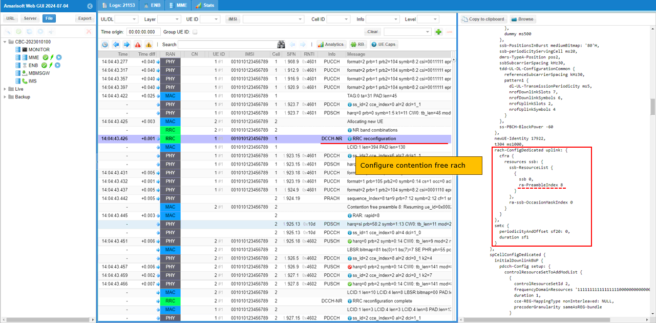
In this RRC Reconfiguration message, you can confirm that contention-free RACH is configured for the handover. The important field is rach-ConfigDedicated uplink. This IE includes cfra, which means the UE is given a dedicated contention-free random access resource for the target cell.
In this example, the configuration shows resources ssb, ssb-ResourceList, ssb 0, and ra-PreambleIndex 8. This means the UE is instructed to use the specific RACH preamble index 8 during the handover access procedure. Since the preamble is assigned by the gNB, the UE does not need to randomly select a contention-based preamble. The log also shows ra-ssb-OccasionMaskIndex 0 and smtc configuration with periodicityAndOffset sf20 and duration sf1. These parameters define the SSB-based RACH occasion and measurement timing related to the target cell.
This is the key difference from the previous blind handover test. In the previous test, the UE performed normal RACH after receiving the handover command. In this test, the handover command includes rach-ConfigDedicated, so the UE performs contention-free RACH using the assigned ra-PreambleIndex.
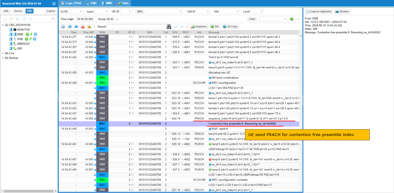
Then confirm that the UE actually sends PRACH using the contention-free preamble configured by the gNB. In the previous RRC Reconfiguration, the gNB assigned ra-PreambleIndex 8 in rach-ConfigDedicated. In this log, the PRACH line shows sequence_index=8, and the MAC log explicitly shows Contention free preamble 8. This confirms that the UE did not randomly select a contention-based preamble. Instead, it used the dedicated preamble assigned for the handover. After that, the gNB sends RAR and resumes the UE context on the target cell. This is the main confirmation point for contention-free RACH in this blind handover test.
RRC / NAS Signaling
RrcReconfiguration
: This is the RrcReconfiguration message sent by eNB to configure Handover (
NOTE : You would see some IEs that has a specific assigned vale here, but consider it as just an example value. Those values should vary depending on test requirement){
message c1: rrcReconfiguration: {
rrc-TransactionIdentifier 0,
criticalExtensions rrcReconfiguration: {
radioBearerConfig {
srb-ToAddModList {
{
srb-Identity 1,
reestablishPDCP true
},
{
srb-Identity 2,
reestablishPDCP true
}
},
drb-ToAddModList {
{
drb-Identity 1,
reestablishPDCP true
}
}
},
nonCriticalExtension {
masterCellGroup {
cellGroupId 0,
rlc-BearerToAddModList {
{
logicalChannelIdentity 4,
reestablishRLC true
},
{
logicalChannelIdentity 1,
reestablishRLC true
},
{
logicalChannelIdentity 2,
reestablishRLC true
}
},
mac-CellGroupConfig {
schedulingRequestConfig {
schedulingRequestToAddModList {
{
schedulingRequestId 0,
sr-TransMax n64
}
}
},
bsr-Config {
periodicBSR-Timer sf20,
retxBSR-Timer sf320
},
tag-Config {
tag-ToAddModList {
{
tag-Id 0,
timeAlignmentTimer infinity
}
}
},
phr-Config setup: {
phr-PeriodicTimer sf500,
phr-ProhibitTimer sf200,
phr-Tx-PowerFactorChange dB3,
multiplePHR FALSE,
dummy FALSE,
phr-Type2OtherCell FALSE,
phr-ModeOtherCG real
},
skipUplinkTxDynamic FALSE,
dataInactivityTimer release: NULL
},
physicalCellGroupConfig {
pdsch-HARQ-ACK-Codebook dynamic
},
spCellConfig {
reconfigurationWithSync {
spCellConfigCommon {
physCellId 501,
downlinkConfigCommon {
frequencyInfoDL {
absoluteFrequencySSB 712608,
frequencyBandList {
79
},
absoluteFrequencyPointA 712062,
scs-SpecificCarrierList {
{
offsetToCarrier 0,
subcarrierSpacing kHz30,
carrierBandwidth 106
}
}
},
initialDownlinkBWP {
genericParameters {
locationAndBandwidth 28875,
subcarrierSpacing kHz30
},
pdcch-ConfigCommon setup: {
controlResourceSetZero 4,
searchSpaceZero 0,
commonSearchSpaceList {
{
searchSpaceId 1,
controlResourceSetId 0,
monitoringSlotPeriodicityAndOffset sl1: NULL,
monitoringSymbolsWithinSlot '10000000000000'B,
nrofCandidates {
aggregationLevel1 n0,
aggregationLevel2 n0,
aggregationLevel4 n4,
aggregationLevel8 n0,
aggregationLevel16 n0
},
searchSpaceType common: {
dci-Format0-0-AndFormat1-0 {
}
}
}
},
searchSpaceSIB1 0,
searchSpaceOtherSystemInformation 1,
pagingSearchSpace 1,
ra-SearchSpace 1
},
pdsch-ConfigCommon setup: {
pdsch-TimeDomainAllocationList {
{
mappingType typeA,
startSymbolAndLength 40
},
{
mappingType typeA,
startSymbolAndLength 57
}
}
}
}
},
uplinkConfigCommon {
frequencyInfoUL {
scs-SpecificCarrierList {
{
offsetToCarrier 0,
subcarrierSpacing kHz30,
carrierBandwidth 106
}
}
},
initialUplinkBWP {
genericParameters {
locationAndBandwidth 28875,
subcarrierSpacing kHz30
},
rach-ConfigCommon setup: {
rach-ConfigGeneric {
prach-ConfigurationIndex 160,
msg1-FDM one,
msg1-FrequencyStart 7,
zeroCorrelationZoneConfig 15,
preambleReceivedTargetPower -110,
preambleTransMax n7,
powerRampingStep dB4,
ra-ResponseWindow sl20
},
ssb-perRACH-OccasionAndCB-PreamblesPerSSB one: n8,
ra-ContentionResolutionTimer sf64,
prach-RootSequenceIndex l139: 1,
msg1-SubcarrierSpacing kHz30,
restrictedSetConfig unrestrictedSet
},
pusch-ConfigCommon setup: {
pusch-TimeDomainAllocationList {
{
k2 7,
mappingType typeA,
startSymbolAndLength 27
},
{
k2 4,
mappingType typeA,
startSymbolAndLength 27
},
{
k2 2,
mappingType typeA,
startSymbolAndLength 27
}
},
p0-NominalWithGrant -84
},
pucch-ConfigCommon setup: {
pucch-ResourceCommon 11,
pucch-GroupHopping neither,
p0-nominal -90
}
},
dummy ms500
},
ssb-PositionsInBurst mediumBitmap: '80'H,
ssb-periodicityServingCell ms20,
dmrs-TypeA-Position pos2,
ssbSubcarrierSpacing kHz30,
tdd-UL-DL-ConfigurationCommon {
referenceSubcarrierSpacing kHz30,
pattern1 {
dl-UL-TransmissionPeriodicity ms5,
nrofDownlinkSlots 7,
nrofDownlinkSymbols 6,
nrofUplinkSlots 2,
nrofUplinkSymbols 4
}
},
ss-PBCH-BlockPower -60
},
newUE-Identity 17922,
t304 ms1000,
smtc {
periodicityAndOffset sf20: 0,
duration sf1
}
},
spCellConfigDedicated {
initialDownlinkBWP {
pdcch-Config setup: {
controlResourceSetToAddModList {
{
controlResourceSetId 2,
frequencyDomainResources '111111111111111110000000000000000000000000000'B,
duration 1,
cce-REG-MappingType nonInterleaved: NULL,
precoderGranularity sameAsREG-bundle
}
},
searchSpacesToAddModList {
{
searchSpaceId 2,
controlResourceSetId 2,
monitoringSlotPeriodicityAndOffset sl1: NULL,
monitoringSymbolsWithinSlot '10000000000000'B,
nrofCandidates {
aggregationLevel1 n0,
aggregationLevel2 n2,
aggregationLevel4 n1,
aggregationLevel8 n0,
aggregationLevel16 n0
},
searchSpaceType ue-Specific: {
dci-Formats formats0-1-And-1-1
}
}
}
},
pdsch-Config setup: {
dmrs-DownlinkForPDSCH-MappingTypeA setup: {
dmrs-AdditionalPosition pos1
},
tci-StatesToAddModList {
{
tci-StateId 0,
qcl-Type1 {
referenceSignal ssb: 0,
qcl-Type typeD
}
}
},
resourceAllocation resourceAllocationType1,
rbg-Size config1,
mcs-Table qam256,
prb-BundlingType staticBundling: {
bundleSize wideband
},
zp-CSI-RS-ResourceToAddModList {
{
zp-CSI-RS-ResourceId 0,
resourceMapping {
frequencyDomainAllocation row4: '001'B,
nrofPorts p4,
firstOFDMSymbolInTimeDomain 4,
cdm-Type fd-CDM2,
density one: NULL,
freqBand {
startingRB 0,
nrofRBs 108
}
},
periodicityAndOffset slots80: 1
}
},
p-ZP-CSI-RS-ResourceSet setup: {
zp-CSI-RS-ResourceSetId 0,
zp-CSI-RS-ResourceIdList {
0
}
}
}
},
firstActiveDownlinkBWP-Id 0,
uplinkConfig {
initialUplinkBWP {
pucch-Config setup: {
resourceSetToAddModList {
{
pucch-ResourceSetId 0,
resourceList {
0,
1,
2,
3,
4,
5,
6,
7
}
},
{
pucch-ResourceSetId 1,
resourceList {
8,
9,
10,
11
}
}
},
resourceToAddModList {
{
pucch-ResourceId 0,
startingPRB 105,
intraSlotFrequencyHopping enabled,
secondHopPRB 0,
format format1: {
initialCyclicShift 1,
nrofSymbols 14,
startingSymbolIndex 0,
timeDomainOCC 0
}
},
{
pucch-ResourceId 1,
startingPRB 105,
intraSlotFrequencyHopping enabled,
secondHopPRB 0,
format format1: {
initialCyclicShift 5,
nrofSymbols 14,
startingSymbolIndex 0,
timeDomainOCC 0
}
},
{
pucch-ResourceId 2,
startingPRB 105,
intraSlotFrequencyHopping enabled,
secondHopPRB 0,
format format1: {
initialCyclicShift 9,
nrofSymbols 14,
startingSymbolIndex 0,
timeDomainOCC 0
}
},
{
pucch-ResourceId 3,
startingPRB 105,
intraSlotFrequencyHopping enabled,
secondHopPRB 0,
format format1: {
initialCyclicShift 1,
nrofSymbols 14,
startingSymbolIndex 0,
timeDomainOCC 1
}
},
{
pucch-ResourceId 4,
startingPRB 105,
intraSlotFrequencyHopping enabled,
secondHopPRB 0,
format format1: {
initialCyclicShift 5,
nrofSymbols 14,
startingSymbolIndex 0,
timeDomainOCC 1
}
},
{
pucch-ResourceId 5,
startingPRB 105,
intraSlotFrequencyHopping enabled,
secondHopPRB 0,
format format1: {
initialCyclicShift 9,
nrofSymbols 14,
startingSymbolIndex 0,
timeDomainOCC 1
}
},
{
pucch-ResourceId 6,
startingPRB 105,
intraSlotFrequencyHopping enabled,
secondHopPRB 0,
format format1: {
initialCyclicShift 1,
nrofSymbols 14,
startingSymbolIndex 0,
timeDomainOCC 2
}
},
{
pucch-ResourceId 7,
startingPRB 105,
intraSlotFrequencyHopping enabled,
secondHopPRB 0,
format format1: {
initialCyclicShift 5,
nrofSymbols 14,
startingSymbolIndex 0,
timeDomainOCC 2
}
},
{
pucch-ResourceId 8,
startingPRB 1,
intraSlotFrequencyHopping enabled,
secondHopPRB 104,
format format2: {
nrofPRBs 1,
nrofSymbols 2,
startingSymbolIndex 0
}
},
{
pucch-ResourceId 9,
startingPRB 1,
intraSlotFrequencyHopping enabled,
secondHopPRB 104,
format format2: {
nrofPRBs 1,
nrofSymbols 2,
startingSymbolIndex 2
}
},
{
pucch-ResourceId 10,
startingPRB 1,
intraSlotFrequencyHopping enabled,
secondHopPRB 104,
format format2: {
nrofPRBs 1,
nrofSymbols 2,
startingSymbolIndex 4
}
},
{
pucch-ResourceId 11,
startingPRB 1,
intraSlotFrequencyHopping enabled,
secondHopPRB 104,
format format2: {
nrofPRBs 1,
nrofSymbols 2,
startingSymbolIndex 6
}
},
{
pucch-ResourceId 12,
startingPRB 105,
intraSlotFrequencyHopping enabled,
secondHopPRB 0,
format format1: {
initialCyclicShift 9,
nrofSymbols 14,
startingSymbolIndex 0,
timeDomainOCC 2
}
},
{
pucch-ResourceId 13,
startingPRB 1,
intraSlotFrequencyHopping enabled,
secondHopPRB 104,
format format2: {
nrofPRBs 1,
nrofSymbols 2,
startingSymbolIndex 8
}
}
},
format1 setup: {
},
format2 setup: {
maxCodeRate zeroDot25
},
schedulingRequestResourceToAddModList {
{
schedulingRequestResourceId 1,
schedulingRequestID 0,
periodicityAndOffset sl40: 8,
resource 12
}
},
dl-DataToUL-ACK {
8,
7,
6,
5,
4,
12,
11
}
},
pusch-Config setup: {
txConfig codebook,
dmrs-UplinkForPUSCH-MappingTypeA setup: {
dmrs-AdditionalPosition pos1,
transformPrecodingDisabled {
}
},
pusch-PowerControl {
msg3-Alpha alpha1,
p0-AlphaSets {
{
p0-PUSCH-AlphaSetId 0,
p0 0,
alpha alpha1
}
},
pathlossReferenceRSToAddModList {
{
pusch-PathlossReferenceRS-Id 0,
referenceSignal ssb-Index: 0
}
},
sri-PUSCH-MappingToAddModList {
{
sri-PUSCH-PowerControlId 0,
sri-PUSCH-PathlossReferenceRS-Id 0,
sri-P0-PUSCH-AlphaSetId 0,
sri-PUSCH-ClosedLoopIndex i0
}
}
},
resourceAllocation resourceAllocationType1,
mcs-Table qam256,
mcs-TableTransformPrecoder qam256,
codebookSubset nonCoherent,
maxRank 1,
uci-OnPUSCH setup: {
betaOffsets semiStatic: {
betaOffsetACK-Index1 9,
betaOffsetACK-Index2 9,
betaOffsetACK-Index3 9,
betaOffsetCSI-Part1-Index1 7,
betaOffsetCSI-Part1-Index2 7,
betaOffsetCSI-Part2-Index1 7,
betaOffsetCSI-Part2-Index2 7
},
scaling f1
}
},
srs-Config setup: {
srs-ResourceSetToAddModList {
{
srs-ResourceSetId 0,
srs-ResourceIdList {
0
},
resourceType aperiodic: {
aperiodicSRS-ResourceTrigger 1,
slotOffset 7
},
usage codebook,
p0 -84,
pathlossReferenceRS ssb-Index: 0
}
},
srs-ResourceToAddModList {
{
srs-ResourceId 0,
nrofSRS-Ports port1,
transmissionComb n2: {
combOffset-n2 0,
cyclicShift-n2 0
},
resourceMapping {
startPosition 0,
nrofSymbols n1,
repetitionFactor n1
},
freqDomainPosition 0,
freqDomainShift 9,
freqHopping {
c-SRS 22,
b-SRS 3,
b-hop 0
},
groupOrSequenceHopping neither,
resourceType aperiodic: {
},
sequenceId 501
}
}
}
},
firstActiveUplinkBWP-Id 0,
pusch-ServingCellConfig setup: {
}
},
pdcch-ServingCellConfig setup: {
},
pdsch-ServingCellConfig setup: {
nrofHARQ-ProcessesForPDSCH n16,
maxMIMO-Layers 2
},
csi-MeasConfig setup: {
nzp-CSI-RS-ResourceToAddModList {
{
nzp-CSI-RS-ResourceId 0,
resourceMapping {
frequencyDomainAllocation other: '000001'B,
nrofPorts p2,
firstOFDMSymbolInTimeDomain 3,
cdm-Type fd-CDM2,
density one: NULL,
freqBand {
startingRB 0,
nrofRBs 108
}
},
powerControlOffset 0,
scramblingID 501,
periodicityAndOffset slots80: 1,
qcl-InfoPeriodicCSI-RS 0
},
{
nzp-CSI-RS-ResourceId 1,
resourceMapping {
frequencyDomainAllocation row1: '1'H,
nrofPorts p1,
firstOFDMSymbolInTimeDomain 5,
cdm-Type noCDM,
density three: NULL,
freqBand {
startingRB 0,
nrofRBs 108
}
},
powerControlOffset 0,
scramblingID 501,
periodicityAndOffset slots80: 1,
qcl-InfoPeriodicCSI-RS 0
},
{
nzp-CSI-RS-ResourceId 2,
resourceMapping {
frequencyDomainAllocation row1: '1'H,
nrofPorts p1,
firstOFDMSymbolInTimeDomain 9,
cdm-Type noCDM,
density three: NULL,
freqBand {
startingRB 0,
nrofRBs 108
}
},
powerControlOffset 0,
scramblingID 501,
periodicityAndOffset slots80: 1,
qcl-InfoPeriodicCSI-RS 0
},
{
nzp-CSI-RS-ResourceId 3,
resourceMapping {
frequencyDomainAllocation row1: '1'H,
nrofPorts p1,
firstOFDMSymbolInTimeDomain 5,
cdm-Type noCDM,
density three: NULL,
freqBand {
startingRB 0,
nrofRBs 108
}
},
powerControlOffset 0,
scramblingID 501,
periodicityAndOffset slots80: 2,
qcl-InfoPeriodicCSI-RS 0
},
{
nzp-CSI-RS-ResourceId 4,
resourceMapping {
frequencyDomainAllocation row1: '1'H,
nrofPorts p1,
firstOFDMSymbolInTimeDomain 9,
cdm-Type noCDM,
density three: NULL,
freqBand {
startingRB 0,
nrofRBs 108
}
},
powerControlOffset 0,
scramblingID 501,
periodicityAndOffset slots80: 2,
qcl-InfoPeriodicCSI-RS 0
}
},
nzp-CSI-RS-ResourceSetToAddModList {
{
nzp-CSI-ResourceSetId 0,
nzp-CSI-RS-Resources {
0
}
},
{
nzp-CSI-ResourceSetId 1,
nzp-CSI-RS-Resources {
1,
2,
3,
4
},
trs-Info true
}
},
csi-IM-ResourceToAddModList {
{
csi-IM-ResourceId 0,
csi-IM-ResourceElementPattern pattern1: {
subcarrierLocation-p1 s0,
symbolLocation-p1 4
},
freqBand {
startingRB 0,
nrofRBs 108
},
periodicityAndOffset slots80: 1
}
},
csi-IM-ResourceSetToAddModList {
{
csi-IM-ResourceSetId 0,
csi-IM-Resources {
0
}
}
},
csi-ResourceConfigToAddModList {
{
csi-ResourceConfigId 0,
csi-RS-ResourceSetList nzp-CSI-RS-SSB: {
nzp-CSI-RS-ResourceSetList {
0
}
},
bwp-Id 0,
resourceType periodic
},
{
csi-ResourceConfigId 1,
csi-RS-ResourceSetList csi-IM-ResourceSetList: {
0
},
bwp-Id 0,
resourceType periodic
},
{
csi-ResourceConfigId 2,
csi-RS-ResourceSetList nzp-CSI-RS-SSB: {
nzp-CSI-RS-ResourceSetList {
1
}
},
bwp-Id 0,
resourceType periodic
}
},
csi-ReportConfigToAddModList {
{
reportConfigId 0,
resourcesForChannelMeasurement 0,
csi-IM-ResourcesForInterference 1,
reportConfigType periodic: {
reportSlotConfig slots80: 9,
pucch-CSI-ResourceList {
{
uplinkBandwidthPartId 0,
pucch-Resource 13
}
}
},
reportQuantity cri-RI-PMI-CQI: NULL,
reportFreqConfiguration {
cqi-FormatIndicator widebandCQI,
pmi-FormatIndicator widebandPMI
},
timeRestrictionForChannelMeasurements notConfigured,
timeRestrictionForInterferenceMeasurements notConfigured,
codebookConfig {
codebookType type1: {
subType typeI-SinglePanel: {
nrOfAntennaPorts two: {
twoTX-CodebookSubsetRestriction '111111'B
},
typeI-SinglePanel-ri-Restriction '03'H
},
codebookMode 1
}
},
groupBasedBeamReporting disabled: {
},
cqi-Table table2,
subbandSize value1
}
}
},
tag-Id 0,
servingCellMO 1,
lte-CRS-ToMatchAround release: NULL
}
}
},
masterKeyUpdate {
keySetChangeIndicator FALSE,
nextHopChainingCount 0
}
}
}
}
}
-
Configuration Steps: