NR SA Band Change
The purpose of this tutorial is to show you how to change carrier band/frequency in NR SA. It is simple in terms of setting parameters in terms of syntax, but it would be tricky to figure out proper band/frequency that is applicable to your DUT. It is assumed that you don't have any previous experience with Amari callbox.
In most cases, Amarisoft can support the most of the band defined in 3GPP but there would be some restrictions to support some of FR2 frequency as listed below.
- FR1 : Amarisoft callbox support any band defined in 3GPP (Same applies to Amarisoft UEsim)
- FR2 : Amarisoft callbox support n257, n258, n260, n261, but does not support n262, n263 as of now. (As of now, Amarisoft UEsim does not support FR2)
Changing Band and Bandwidth change in NR is not as simple/straightforward as in LTE since it requires to change several different information elements in RRC message and figuring out those value is not so simple. But this process is simplified greatly in Amaricall box since RRC configuration is automatically set by Callbox. What you have to do is to set a few key configuration parameters set to be valid as per 3GPP specification.
Table of Contents
Introduction
5G New Radio Standalone (NR SA) represents a transformative step in mobile communications, enabling devices to operate independently of legacy LTE networks by leveraging a dedicated 5G core. Within this context, the ability to modify carrier bands and frequencies is crucial for testing, optimization, and deployment of 5G solutions. Carrier band and frequency selection in NR SA is inherently complex due to the diversity of spectrum allocations, intricate RRC (Radio Resource Control) signaling, and strict adherence to 3GPP specifications. Amarisoft's Amari Callbox offers a powerful and flexible platform for emulating 5G networks and devices, simplifying otherwise challenging configuration tasks through automated RRC and NAS (Non-Access Stratum) handling. With support for a wide range of frequency bands—including comprehensive FR1 (Sub-6 GHz) coverage and selected FR2 (mmWave) bands—Amari Callbox streamlines 5G experimentation. However, users must still ensure compatibility between device-under-test (DUT), supported bands, and the callbox configuration. Understanding the underlying architecture, supported spectrum, and configuration principles is essential for effective use of the Amari Callbox in NR SA scenarios. This tutorial provides a structured approach for modifying carrier band and frequency settings, offering both foundational knowledge and practical guidance for users new to the platform.
-
Technology Context
- 5G NR SA enables direct device connectivity to a 5G core network, bypassing LTE infrastructure and unlocking advanced network features.
- Carrier band and frequency configuration is essential for validating 5G device behavior across different radio environments and regulatory domains.
- Amarisoft Amari Callbox acts as a software-defined test platform, automating complex radio configuration through dynamic RRC and NAS management.
- 3GPP compliance is central to configuration; only bands and parameters defined in the specifications are permitted.
-
Relevance and Importance
- Mastering band and frequency changes is fundamental for comprehensive 5G device and network testing.
- Amari Callbox simplifies the configuration process, reducing manual intervention and the risk of misconfiguration.
- The tutorial addresses real-world challenges, such as identifying valid bands for the DUT and understanding hardware/software restrictions.
-
Learning Outcomes
- Gain an understanding of 5G NR SA architecture and its implications for band/frequency configuration.
- Learn to identify and select appropriate bands and frequencies compatible with both the Amari Callbox and DUT.
- Acquire practical skills in setting up and modifying 5G NR parameters within the Amari Callbox environment.
- Develop awareness of 3GPP band definitions, Amarisoft platform limitations, and interoperability considerations.
-
Prerequisite Knowledge and Skills
- No prior experience with Amari Callbox is required; the tutorial is designed for beginners.
- Basic understanding of wireless communication concepts (e.g., frequency bands, bandwidth, radio access technologies) is helpful.
- Familiarity with 3GPP specifications and terminology (such as FR1/FR2, NR, DUT) will enhance comprehension but is not strictly mandatory.
Summary of the Tutorial
This tutorial covers test procedures for configuring and verifying the SSB (Synchronization Signal Block) position in NR SA (Standalone) mode for band N41 with 20 MHz bandwidth, using Amarisoft gNB software. Two main tests are described: automatic and manual SSB position configuration. The summary below details the setup, key checks, configuration steps, execution, and analysis methodologies for both tests, as well as notes on common errors.
-
Test Setup
- Use the SIM card delivered with the system; refer to the Configuration Guide for changes.
- Ensure test band and bandwidth validity by referencing 3GPP specs (38.101-1 Table 5.2-1, Table 5.3.5-1; 38.104 Table 5.4.3.3-1).
- Verify DUT (Device Under Test) capability for the selected band and bandwidth through internal specs or UE Capability Information messages.
-
Key Configuration Parameters
- Essential parameters: band, bandwidth, dl_nr_arfcn, subcarrier_spacing.
-
Test 1: NR/SA-N41-20MHz, Automatic SSB Position
-
Configuration
- Use a modified gnb-sa-n41-20M.cfg file, copied from gnb-sa.cfg.
- Set NR_BANDWIDTH to 20 MHz, configure band and dl_nr_arfcn, but do not set SSB position (gscn parameter).
- Amarisoft gNB automatically determines SSB position, typically near the lower end of the channel frequency.
-
Performing the Test
- Start LTE service and inspect cell configuration in the (enb) interface to confirm bandwidth settings.
- Verify that SSB ARFCN is automatically set.
- Power on UE and allow it to complete the attach process.
-
Log Analysis
- Examine /tmp/gnb0.log for SSB and CORESET0 parameters automatically configured by the callbox.
- Key parameters to check:
- ssb_arfcn: SSB center frequency (convertible to MHz or GSCN via online tools).
- ssb_prb: SSB position in PRB.
- k_ssb: Offset in subcarrier units from lowest PRB of SSB.
- coreset0_prb: CORESET0 position in PRB.
- WebGUI log displays bandwidth configurations for downlink and uplink, which are set based on the configuration file.
-
Configuration
-
Test 2: NR/SA-N41-20MHz, Manual Configuration of SSB Position
-
Determine Band / ARFCN
- Select a valid GSCN for the intended band and subcarrier spacing using external tools (https://www.sqimway.com/nr_raster.php).
- Verify that the chosen GSCN is a valid ARFCN for the band using available references.
-
Configuration
- Use a modified gnb-sa-n41-20M-gscn.cfg file, based on gnb-sa.cfg.
- Add the gscn parameter to specify SSB position manually.
- Ensure the gscn value is valid for the selected band, bandwidth, and subcarrier spacing.
-
Performing the Test
- Run LTE service and review cell configuration in (enb) to confirm settings for bandwidth, band, and SSB position (noting SSB position in ARFCN units).
- Power on UE and allow it to complete the attach process.
-
Log Analysis
- Inspect /tmp/gnb0.log for confirmation of SSB and CORESET0 configuration.
- Parameters to review:
- ssb_arfcn, ssb_prb, k_ssb, coreset0_prb.
- WebGUI log can be used to verify bandwidth-related configurations.
-
Determine Band / ARFCN
-
Frequent Errors and Troubleshooting
-
“the DL frequency must be a multiple of XXX kHz”
- This error occurs when the ARFCN is not aligned with the specified raster frequency for the band as defined in 3GPP.
-
“cell bandwidth does not fit in band definition”
- Error appears if the ARFCN is set too low or too high, causing the configured bandwidth to exceed the band’s lower or upper limits.
-
“the DL frequency must be a multiple of XXX kHz”
This summary provides a high-level description of the test procedures, step-by-step configuration, execution, observation, and troubleshooting approaches for verifying both automatic and manual SSB position settings in SA NR band N41 scenarios using Amarisoft systems.
Test Setup
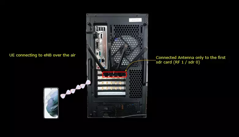
Test setup for this tutorial is as shown below.
- SIM Card used in this tutorial is the one delivered with the system as it is.
- If you want to change the configuration, The tutorial Configuration Guide would help
Check before Trying
1. Check following 3GPP tables and make it sure that the band/bandwidth you are trying to test is valid in terms of 3GPP
- 38.101-1 Table 5.2-1, Table 5.3.5-1
- 38.104 - Table 5.4.3.3-1
2. Check UE capability Information and make it sure that your DUT support the band and bandwidth you want to try
Key Configuration Parameters
Followings are important configuration parameters for this tutorial. You may click on the items for the descriptions from Amarisoft documents.
Test 1 : NR/SA-N41-20Mhz, Automatic SSB Position
In this test, I will show you how SSB Position is determined and configured by default (i.e, set automatically by Amarisoft gNB software). If user does not specify SSB position in the configuration file, Amarisoft gNB automatically determine the SSB position. Usually it puts the SSB near to lower end of channel frequency spectrum to let the coreset 0 positioned at the lowest possible frequency of the channel. The exact default position the SSB varies depending on the band, frequency and bandwidth you set in the configuration file.
Configuration
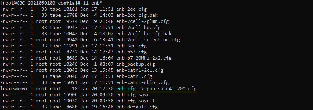
I used the configuration file gnb-sa-n41-20M.cfg which is copied from gnb-sa.cfg and modified.
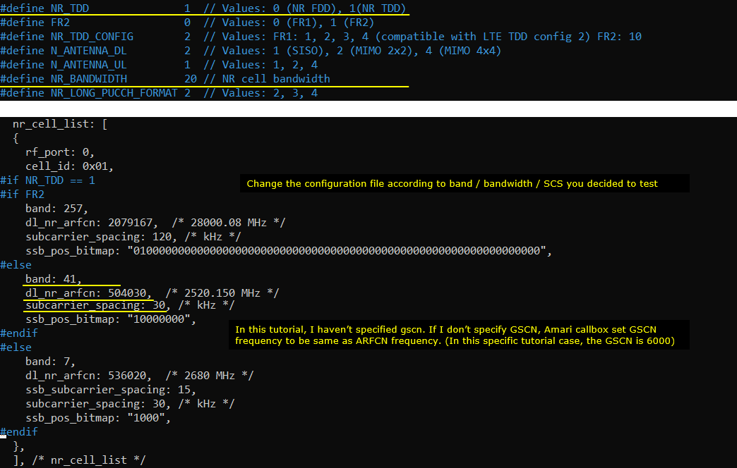
Configuration in gnb-sa-n41-20M.cfg is as shown below. In this configuration, I set NR_BANDWIDTH to 20 Mhz. I configured band, dl_nr_arfcn but I didn't explicitely configured gscn (ssb position) to let gNB automatically determine the position.
Perform the Test
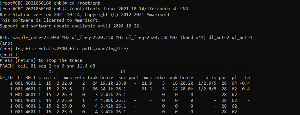
Run LTE service and check cell configuration in (enb) screen as shown below. Confirm that the Bandwidth are configured as you intended. Note that SSB ARFCN is the ssb position automatically set by gNB software.

Power on UE and let it complete the attach
Log Analysis
In this section, I would not go through the full log. I would show you just the parts that are related to the test in this tutorial.
If you open /tmp/gnb0.log file (WebGUI does not show this information), you will see the following information at the beginning. Blue and red lined part is automatically configured by AmariCall box. Red lined part is MIB configuration and it is very tricky to set proper values for these parameters manually and error prone, but these are configured automatically in Amari Callbox. (
- ssb_arfcn indicates the center frequency in arfcn. If you want to convert this to Mhz or to GSCN, you can convert in https://www.sqimway.com/nr_band.php and https://www.sqimway.com/nr_raster.php
- ssb_prb indicates the position of ssb in PRB
- k_ssb indicates the k_ssb position (i.e, offset in subcarrier unit from the lowest PRB of ssb_prb)
- coreset0_prb indicates the position of CORESET0 in PRB unit

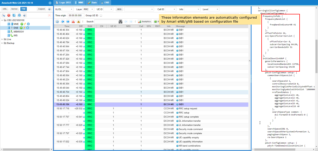
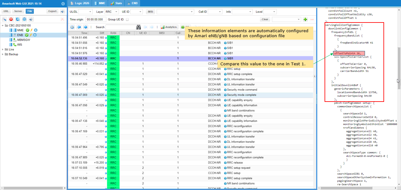
In the WebGUI log, you can easily check the bandwidth related configurations as shown below. The downlink band, bandwidth, subcarrier spacing can be confirmed from frequencyInfoDL and initialDownlinkBWP IE. These IEs are automatically set by gNB software based on the configuration file.
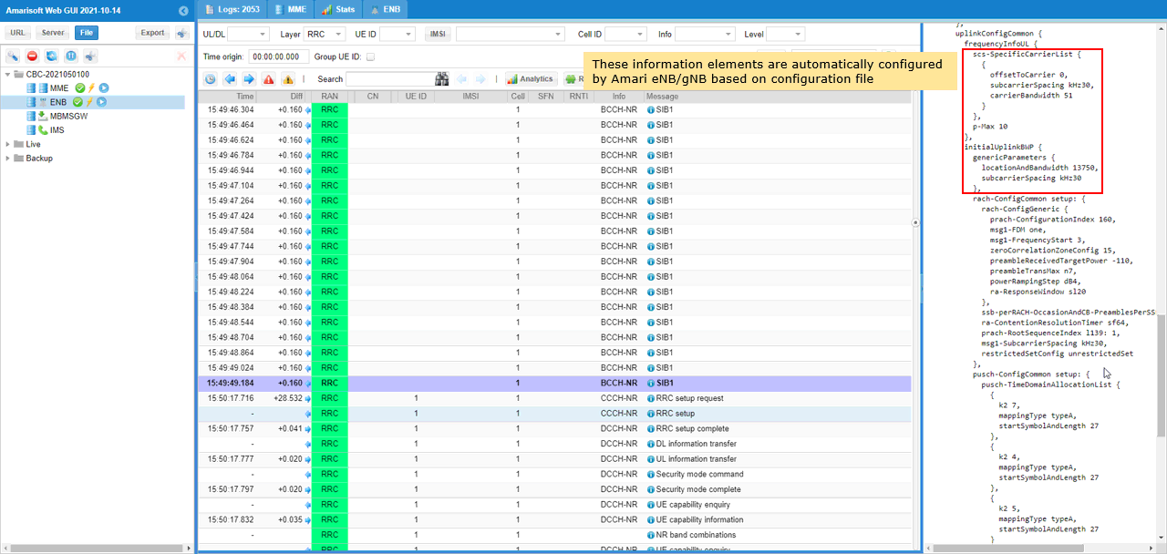
The uplink band, bandwidth, subcarrier spacing can be confirmed from frequencyInfoUL and initialUplinkBWP IE. These IEs are automatically set by gNB software based on the configuration file.
Test 2 : NR/SA-N41-20Mhz, Manual configuration of SSB Position
In this test, I will show you how you can set the position of SSB on your own instead of letting gNB specify the position automatically. Usually this kind of manual configuration is not recommended since it is not an easy task to determined the position without making any mistake since the allowable SSB position varies depending on various factors like channel bandwidth, subcarrier spacing, CORESET0 position etc.
Determine Band / ARFCN
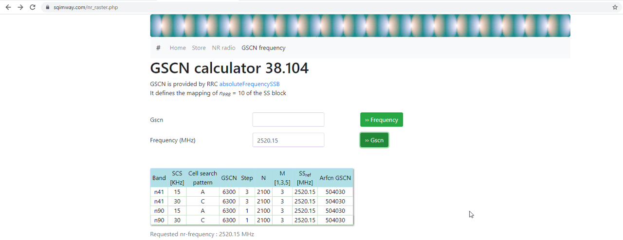
Determine (pick) a GSCN and check if it is valid for the band/SCS that you try.
The tool at the following site would help : https://www.sqimway.com/nr_raster.php . In this tutorial, I decided to try with n41 and picked a frequency as follows.
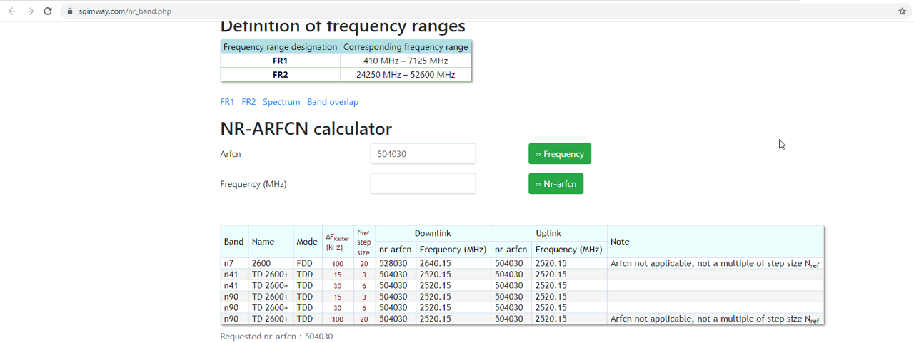
Check if the GSCN frequency you picked is valid ARFCN.
Following site would help you with this : https://www.sqimway.com/nr_band.php
Configuration
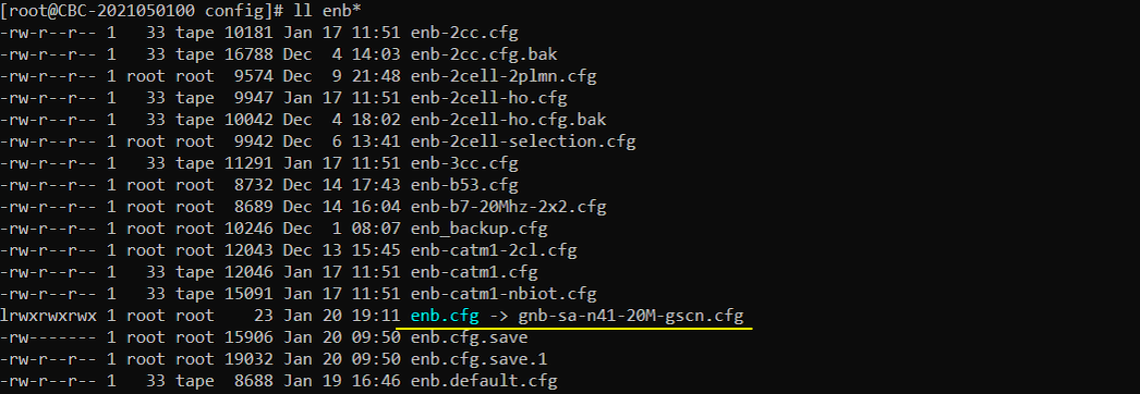
I used the configuration file gnb-sa-n41-20M-gscn.cfg which is copied from gnb-sa.cfg and modified.
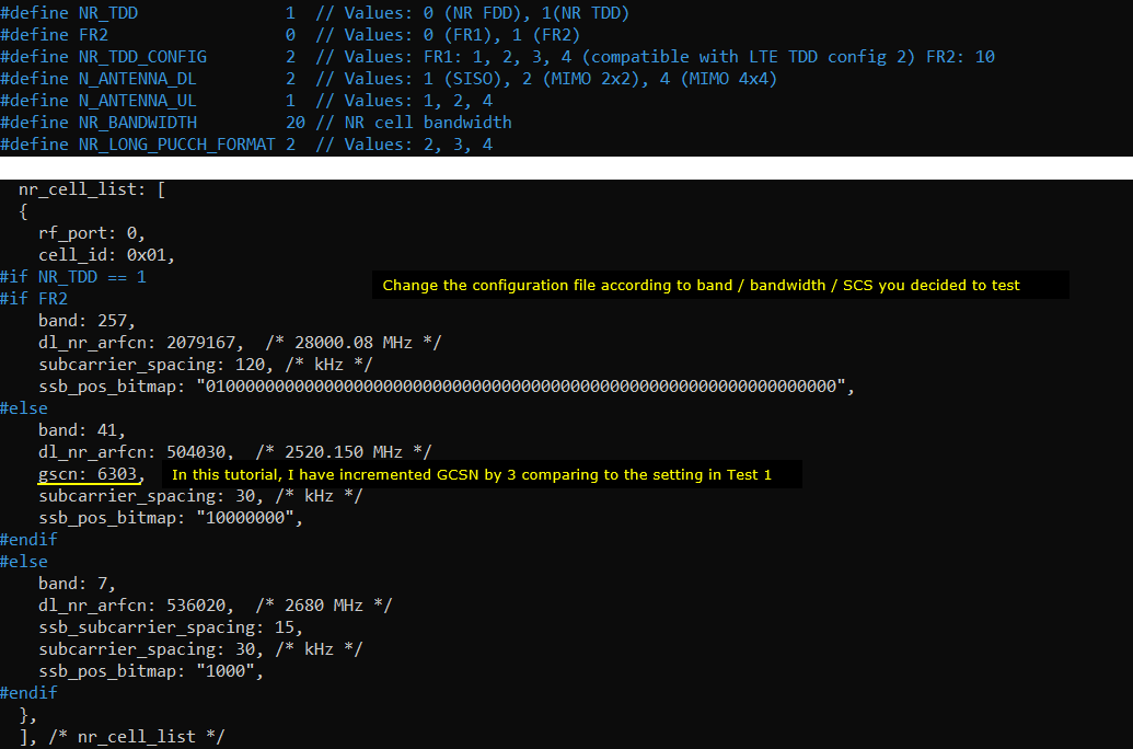
Configured as shown below. I only added gscn parameter to the configuration used in Test 1 Be careful to set the value of gscn. Make it sure that the value is valid in the band, bandwidth, subcarrier spacing etc.
Perform the Test
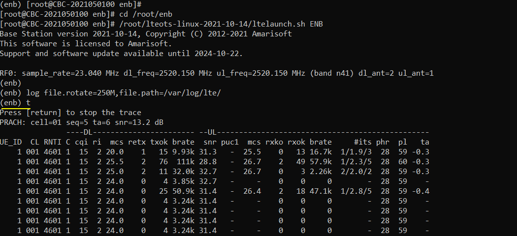
Run LTE service and check cell configuration in (enb) screen as shown below. Confirm that the Bandwidth, band and SSB position are configured as intended. Note that SSB position is printed in ARFCN unit, not in GSCN. If you want to convert this to Mhz or to GSCN, you can convert in https://www.sqimway.com/nr_band.php and https://www.sqimway.com/nr_raster.php

Power on UE and let it complete the attach
Log Analysis
In this section, I would not go through the full log. I would show you just the parts that are related to the test in this tutorial.
If you open /tmp/gnb0.log file (WebGUI does not show this information), you will see the following information at the beginning. Blue and red lined part is automatically configured by AmariCall box. Red lined part is MIB configuration and it is very tricky to set proper values for these parameters manually and error prone, but these are configured automatically in Amari Callbox. (
- ssb_arfcn indicates the center frequency in arfcn. If you want to convert this to Mhz or to GSCN, you can convert in https://www.sqimway.com/nr_band.php and https://www.sqimway.com/nr_raster.php
- ssb_prb indicates the position of ssb in PRB
- k_ssb indicates the k_ssb position (i.e, offset in subcarrier unit from the lowest PRB of ssb_prb)
- coreset0_prb indicates the position of CORESET0 in PRB unit

In the WebGUI log, you can easily check the bandwidth related configurations as shown below.
RRC / NAS Signaling
SIB1 (SA)
: This is the SIB1 message sent by gNB to configure NR SA. (
{
message c1: systemInformationBlockType1: {
...
servingCellConfigCommon {
downlinkConfigCommon {
frequencyInfoDL {
frequencyBandList {
{
freqBandIndicatorNR 78
}
},
...
},
initialDownlinkBWP {
genericParameters {
locationAndBandwidth 13750,
subcarrierSpacing kHz30
},
},
uplinkConfigCommon {
frequencyInfoUL {
scs-SpecificCarrierList {
{
offsetToCarrier 0,
subcarrierSpacing kHz30,
carrierBandwidth 51
}
},
p-Max 10
},
initialUplinkBWP {
genericParameters {
locationAndBandwidth 13750,
subcarrierSpacing kHz30
},
}
rrcConnectionReconfiguration for NR Addition (NSA)
: This is the RRC message sent by eNB (LTE) to add NR. (
message c1: rrcConnectionReconfiguration: {
rrc-TransactionIdentifier 0,
criticalExtensions c1: rrcConnectionReconfiguration-r8: {
....
nonCriticalExtension {
nonCriticalExtension {
nonCriticalExtension {
nonCriticalExtension {
nonCriticalExtension {
nonCriticalExtension {
nonCriticalExtension {
nonCriticalExtension {
nr-Config-r15 setup: {
endc-ReleaseAndAdd-r15 FALSE,
nr-SecondaryCellGroupConfig-r15 {
rrc-TransactionIdentifier 0,
criticalExtensions rrcReconfiguration: {
secondaryCellGroup {
...
spCellConfig {
servCellIndex 1,
reconfigurationWithSync {
spCellConfigCommon {
physCellId 500,
downlinkConfigCommon {
frequencyInfoDL {
absoluteFrequencySSB 632256,
frequencyBandList {
78
},
absoluteFrequencyPointA 632016,
scs-SpecificCarrierList {
{
offsetToCarrier 0,
subcarrierSpacing kHz30,
carrierBandwidth 51
}
}
},
initialDownlinkBWP {
genericParameters {
locationAndBandwidth 13750,
subcarrierSpacing kHz30
},
...
},
uplinkConfigCommon {
frequencyInfoUL {
scs-SpecificCarrierList {
{
offsetToCarrier 0,
subcarrierSpacing kHz30,
carrierBandwidth 51
}
}
},
initialUplinkBWP {
genericParameters {
locationAndBandwidth 13750,
subcarrierSpacing kHz30
},
Frequent Errors
Followings are some of the frequent errors (common errors) you may encounter when you try to set your own band, frequency (arfcn) and bandwidth
the DL frequency must be a multiple of XXX kHz
You would get this error when you set arfcn which is not divisible by the raster frequency specified for each band in 3GPP as shown below.

cell bandwidth does not fit in band definition
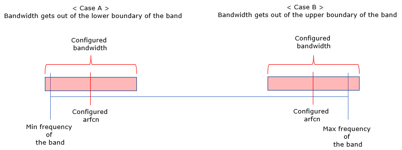
You would get this error when you set arfcn too low or too high so that the configured bandwidth gets out of lower or upper boundary of the band as illustrated below.
