LTE PUCCH
The purpose of this tutorial is to show you how to configure various parameters related to PUCCH. Main purpose is to help you understand the relationship between Amarisoft eNB configuration parameters and LTE RRC configuration for PUCCH. It is important to understand the details of these parameters since PUCCH configuration may affect the UL max throughput and the number of UE that can be supported by eNB.
In LTE, PUCCH is located around the either ends of the spectrum as shown below to utilize the property of frequency diversity. The exact location of PUCCH location and how many RBs are occupied by PUCCH is determined by a few RRC parameters and format of PUCCH.
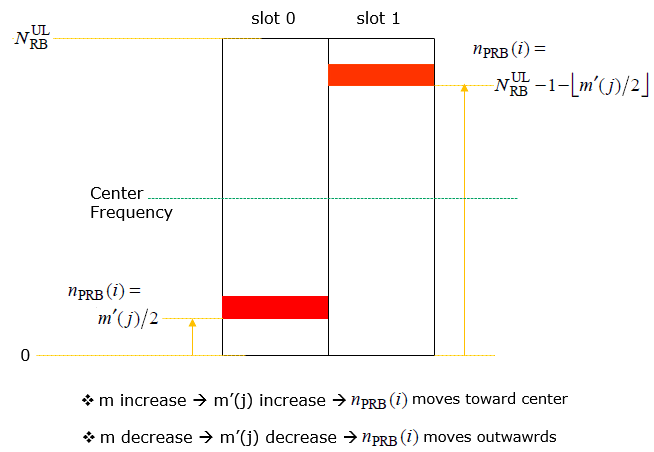
Image Source : Sharetechnote
Table of Contents
- LTE PUCCH
- Introduction
- Summary of the Tutorial
- Test Setup
- Key Configuration Parameters
- Test 1 : SISO, CSI Disabled
- Test 2 : SISO, CSI Disabled : n1PUCCH-AN
- Test 3 : SISO, CSI Enabled
- Test 4 : SISO, CSI Enabled : nRB-CQI
- Test 5 : MIMO, CSI Enabled
- Test 6 : Simulteneous CSI and Ack/Nack
- Test 7 : SIB2 ASN.1 Modification : nCS-AN change
- RRC / NAS Signaling
Introduction
The Physical Uplink Control Channel (PUCCH) is a pivotal component of the LTE (Long Term Evolution) radio interface, responsible for carrying uplink control information such as Hybrid Automatic Repeat Request (HARQ) acknowledgments, scheduling requests, and channel quality indicators from the User Equipment (UE) to the eNodeB (eNB). Architecturally, PUCCH is strategically allocated to the edges of the LTE system bandwidth to exploit frequency diversity, thereby enhancing reliability in the presence of frequency-selective fading. The precise allocation, size, and structure of PUCCH resources are governed by a set of RRC (Radio Resource Control) configuration parameters, which are in turn closely tied to the eNB’s configuration, especially within software-defined platforms like Amarisoft. The relationship between these configuration parameters directly impacts critical network performance metrics, including uplink maximum throughput and the number of UEs supportable within a cell. Understanding how PUCCH operates, its various formats, and the interplay between eNB configuration and RRC parameters is essential for network engineers and operators aiming to optimize LTE uplink control performance and overall system capacity. This tutorial provides a comprehensive exploration of these concepts, equipping learners with the knowledge to effectively configure and troubleshoot PUCCH in real-world LTE deployments.
-
Context and Background
- PUCCH serves as the LTE uplink channel dedicated to control signaling, distinct from the Physical Uplink Shared Channel (PUSCH) which carries user data.
- Located at the edges of the LTE spectrum, PUCCH leverages frequency diversity to resist channel impairments.
- The configuration of PUCCH involves a combination of eNB-specific parameters and standardized RRC signaling, requiring a solid understanding of both LTE protocol architecture and vendor-specific implementations.
-
Relevance and Importance of the Tutorial
- Correct PUCCH configuration is critical for maximizing uplink control reliability, supporting large numbers of UEs, and ensuring optimal network throughput.
- This tutorial bridges the gap between Amarisoft eNB configuration and LTE RRC parameterization, providing practical insights into real-world deployment scenarios.
- Professionals responsible for LTE network planning, optimization, and troubleshooting will benefit from a deep understanding of these mechanisms.
-
Learning Outcomes
- Gain an in-depth understanding of PUCCH architecture and its operational principles within LTE networks.
- Learn to map Amarisoft eNB configuration parameters to corresponding LTE RRC PUCCH settings.
- Develop the ability to assess and optimize the impact of PUCCH parameters on uplink throughput and UE capacity.
- Acquire practical skills for troubleshooting and fine-tuning PUCCH configurations in live LTE environments.
-
Prerequisite Knowledge and Skills
- Familiarity with basic LTE network architecture and protocol stack.
- Understanding of LTE physical layer concepts, including channels and resource blocks.
- Experience with eNB configuration interfaces, particularly with Amarisoft software-defined eNB solutions, is recommended.
- Basic knowledge of RRC signaling and parameter structures is beneficial for following advanced configuration topics.
Summary of the Tutorial
This tutorial provides detailed procedures for testing various PUCCH (Physical Uplink Control Channel) configurations in an LTE system using Amarisoft software. The following summarizes each test scenario, highlighting the procedures, configuration steps, and methodologies applied.
-
Test 1: SISO, CSI Disabled
- Configure eNB using enb-pucch1-dl-siso.cfg (based on enb.default.cfg).
- Set N_ANTENNA_DL to 1 for SISO operation and DISABLE_CSI to 1 to disable CSI reporting.
- Adjust n1_pucch_sr_count and cqi_pucch_n_rb in pucch_dedicated for efficient resource allocation.
- Start the eNB and MME, power on UE, and ensure successful attach.
- Optionally, perform throughput tests (DL/UL) using a speedtest application.
- Analyze logs: Check PUCCH resource allocation, verify parameters in SIB2, and confirm CQI is disabled in relevant configuration and log entries.
- Visualize PUCCH resource usage using PHY logs and RB maps.
-
Test 2: SISO, CSI Disabled, n1PUCCH-AN Variation
- Use enb-pucch1-dl-siso-sr-count.cfg and adjust n1_pucch_sr_count to demonstrate its impact.
- Maintain SISO and CSI-disabled settings as in Test 1.
- Follow the same test execution steps: check configuration, run UE attach, and perform optional speed tests.
- Analyze logs to compare how changes in n1_pucch_sr_count affect physical resource allocation and SIB2 mapping.
-
Test 3: SISO, CSI Enabled
- Configure eNB with enb-pucch-dl-siso-csi.cfg.
- Set N_ANTENNA_DL to 1 and DISABLE_CSI to 0 to enable CSI reporting.
- Set n1_pucch_sr_count and cqi_pucch_n_rb appropriately, noting that cqi_pucch_n_rb = 0 is only allowed if periodic CSI is disabled.
- Run and check procedures as in previous tests.
- Log analysis: Confirm CQI is enabled via SIB2 and RRC messages, and compare resource allocation to previous cases.
-
Test 4: SISO, CSI Enabled, nRB-CQI Variation
- Use enb-pucch-dl-siso-csi-nrbCQI.cfg and modify cqi_pucch_n_rb to demonstrate its impact on resource allocation.
- Maintain SISO and CSI-enabled settings.
- Follow standard run and check procedures.
- Analyze how cqi_pucch_n_rb changes are reflected in SIB2 and physical resource allocation.
-
Test 5: MIMO, CSI Enabled
- Configure eNB with enb-pucch-dl-mimo-csi.cfg (note: N_ANTENNA_DL = 1 in provided steps, but intended for MIMO operation).
- Enable CSI and adjust PUCCH resource configurations appropriately.
- Execute the test as per previous methodology: verify configuration, attach UE, and optionally perform throughput tests.
- Log analysis focuses on the impact of MIMO and CSI on PUCCH resource allocation.
-
Test 6: Simultaneous CSI and Ack/Nack
- Use enb-pucch-dl-siso-csi-an-mux.cfg to test SISO with simultaneous CSI and Ack/Nack reporting.
- Set simultaneousAckNackAndCQI and simultaneousAckNackAndCQI_format3 to true.
- Set force_dl_schedule: true to ensure Ack/Nack is sent every subframe, creating conditions for multiplexed reporting.
- Standard run and check steps, with emphasis on confirming feature support via UE capability and physicalConfigDedicated information.
- Log analysis: Verify correct multiplexing and resource utilization in PHY logs.
-
Test 7: SIB2 ASN.1 Modification (nCS-AN Change)
- Demonstrates changing PUCCH configurations not directly available in configuration files by editing SIB2 ASN.1.
- Use enb-pucch-dl-siso-csi-nCS-AN.cfg and specify a custom sib2_3_nCS-AN.asn file in sib_sched_list.
- Change nCS-AN value within the ASN.1 file and link it to the eNB configuration.
- Execute standard procedures, ensuring the modified SIB2 is used and reflected in the system.
- Analyze logs to verify the new nCS-AN value is present and correctly mapped in SIB2 and system behavior.
Across all tests, the methodology includes:
- Careful adjustment of eNB and MME configuration files to set PUCCH-related parameters.
- Validation of configuration through system logs, PHY layer monitoring, and SIB2 inspection.
- Optional throughput testing to confirm system performance under each configuration.
- Use of graphical and textual log analysis to verify resource allocation and the effect of parameter changes.
Test Setup
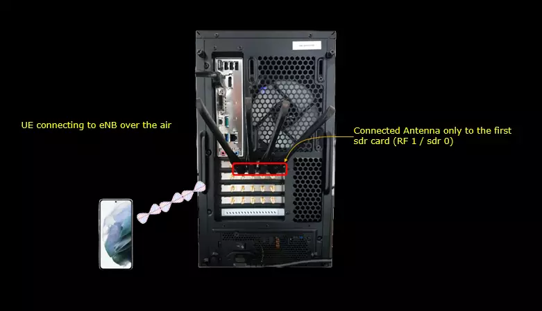
Test setup for this tutorial is as shown below.
- SIM Card used in this tutorial is the one delivered with the system as it is.
- If you want to change the configuration, The tutorial Configuration Guide would help
Key Configuration Parameters
Followings are important configuration parameters for this tutorial. You may click on the items for the descriptions from Amarisoft documents.
- pucch_dedicated : In this link, you would get the descriptions for all the items linked below
- n1_pucch_sr_count
- cqi_pucch_n_rb
- n1_pucch_an_cs_count
- ack_nack_feedback_mode_ca
- n3_pucch_an_n_rb
- simultaneousAckNackAndCQI
- simultaneousAckNackAndCQI_format3
- sr_period
- cqi_period
- m_ri
- forced_cqi
- forced_ri
Test 1 : SISO, CSI Disabled
This test is to show a case of the PUCCH configuration with minium resource allocation : SISO, CSI Disabled.
Configuration
I used the eNB configuration enb-pucch1-dl-siso.cfg which is copied from enb.default.cfg and modified for this tutorial.

I used the mme configuration mme-ims.cfg and ims configuration ims.default.cfg

In enb-pucch1-dl-siso.cfg , PUCCH related configurations are set as follows.
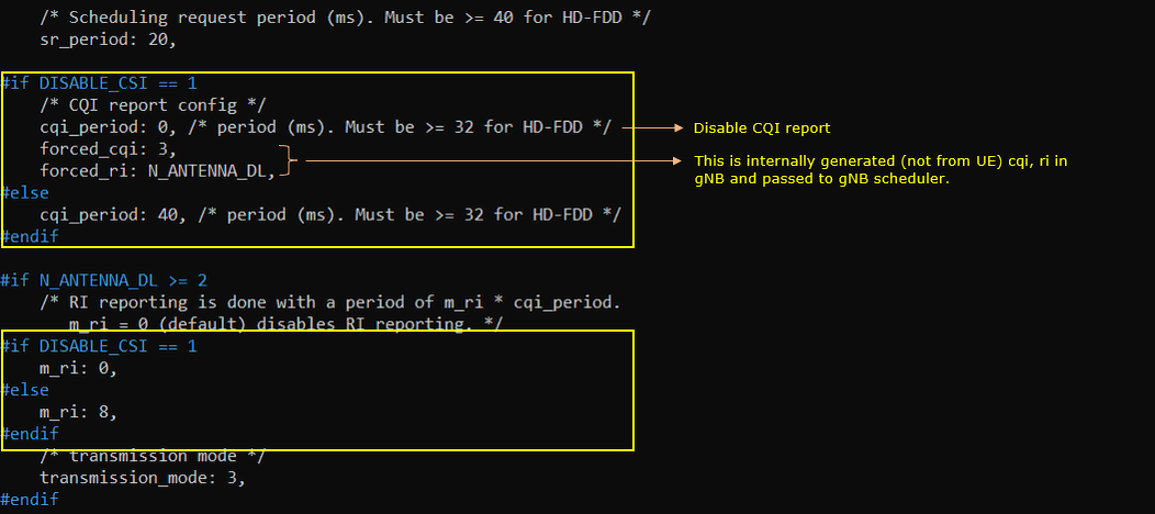
Set N_ANTENNA_DL 1 to configure the cell to SISO and set DISABLE_CSI 1 to disable CSI Report.

Configure n1_pucch_sr_count and cqi_pucch_n_rb in pucch_dedicated configuration to fit with the test configuration. In terms of efficient utilization of the physical resources, it is recommended not to set these unnecessarily large values.

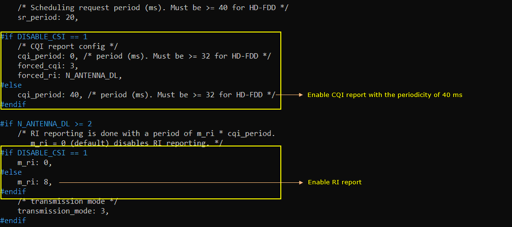
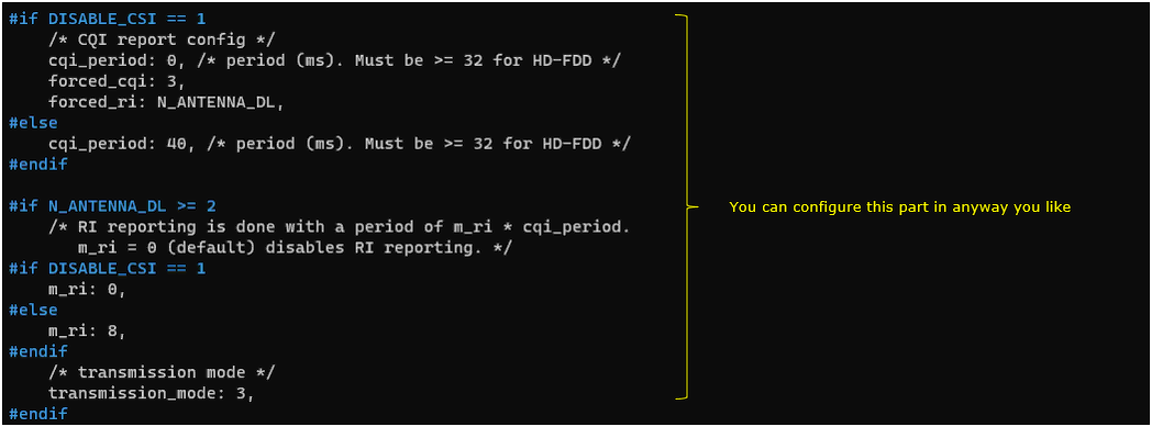
This is just to show how cqi_period, forced_cqi, force_ri, m_ri parameters are set depending on DISABLE_CSI value. This is only for informational purpose. you don't need to modify anything here.
Run and Check
Check the cell phy configuration and see if it is configured as intended.

run 't' command and power on UE and make it sure that UE complete the attach.

(This is not mandatory but) perform some high throughput test for both DL and UL. I ran a speedtest app on internet for this tutorial.
Log Analysis
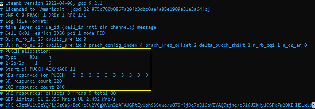
For the analysis of PUCCH log, it would be helpful to check first the meta data in the log file and check the overall information about PUCCH resource allocation. If you open up the enb log in text editor, you will find these information at the beginning of the log.
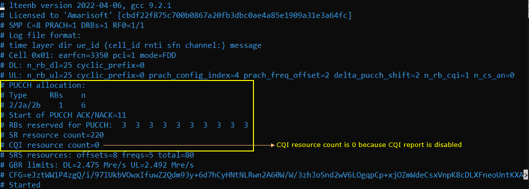
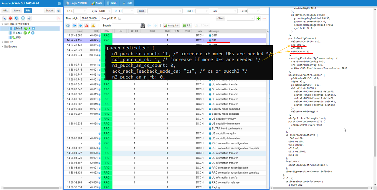
Check out pucch-ConfigCommon in SIB2 and see if the configuration parameter is properly reflected in the message. cqi_pucch_n_rb in configuration file is mapped to nRB-CQI IE in SIB2 and n1_pucch_sr_count in configuration file is mapped to n1PUCCH-AN IE in SIB2.
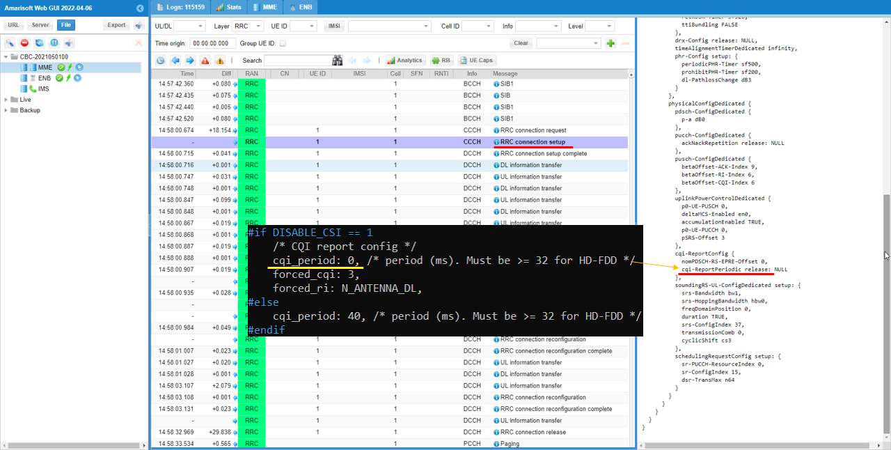
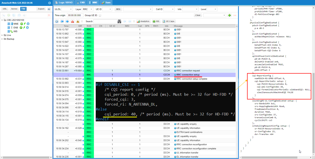
You can confirm that CQI is disabled from cqi-ReportConfig IE in RRC Connection Setup.
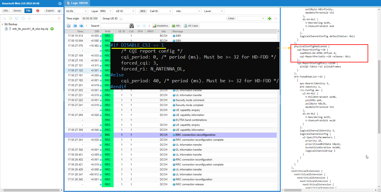
In additon, you can also confirm that CQI is disabled from phsicalConfigDedicated IE in RRC Connection Reconfiguration.
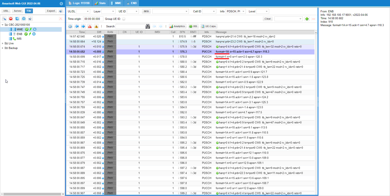
You can confirm with PHY log on which PUCCH formats are used for the test
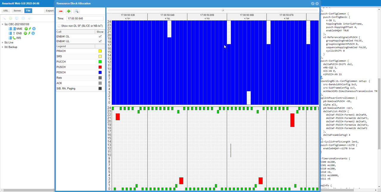
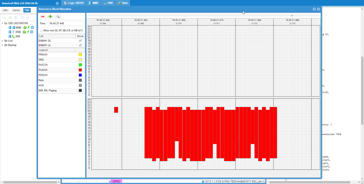
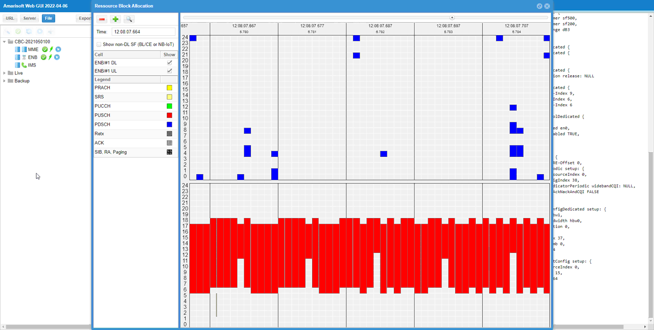
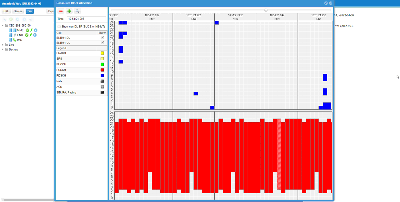
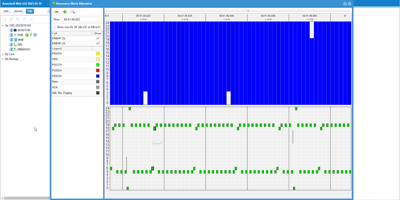
If you check the time period while PDSCH is flowing in RB map, you can easily check out the Uplink physical resources that are really used by PUCCH. The small green rectangles in the lower track indicates the physical resources that are used by PUCCH.
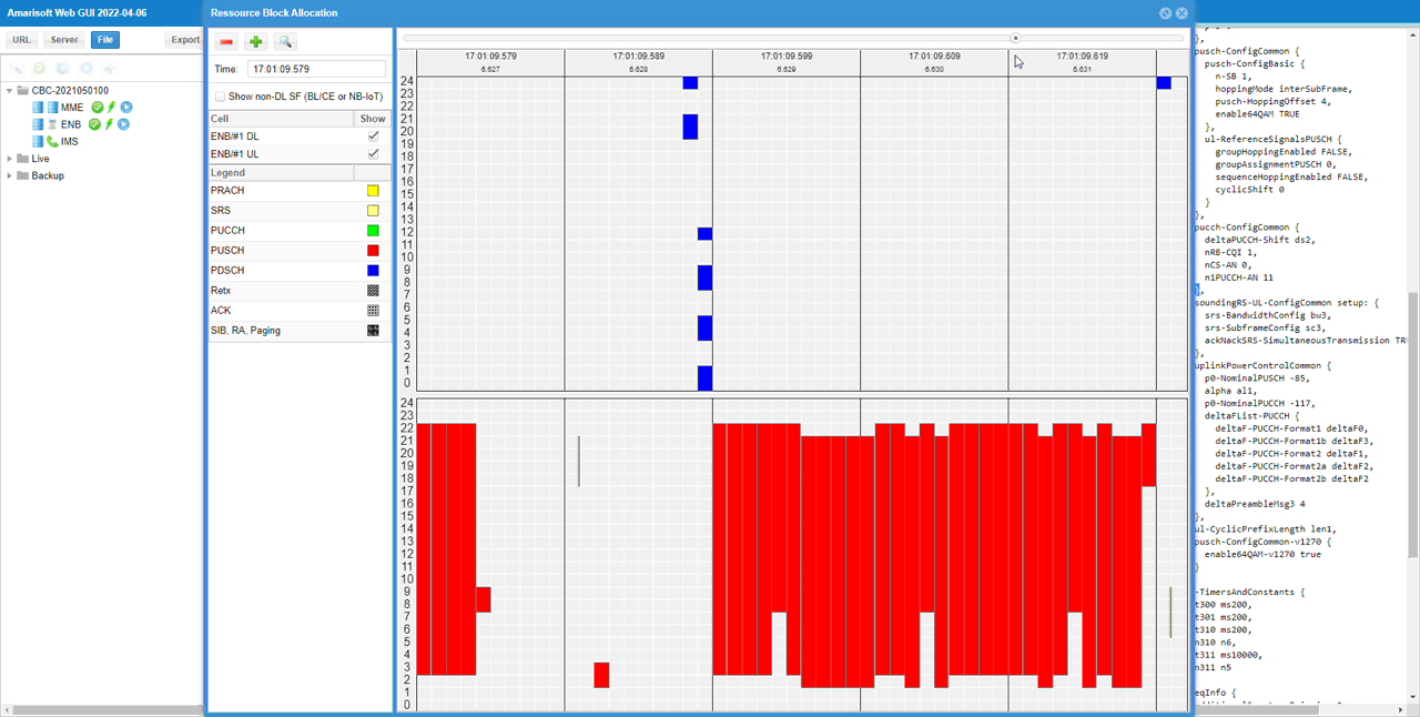
If you look into the period while PUSCH is fully allocated, you can visually confirm the physical resources reserved for PUCCH. The blank space outside of the red block(PUSCH) in lower track is the area reserved for PUCCH. This shows that Amarisoft does not allocate the reserved area for PUSCH even if it is not really used and this way of scheduling would give me a little bit lower maximum throughput than you may expected. If you want to schedule PUSCH even at the reserved area for maximum throughput, check out this tutorial.
Test 2 : SISO, CSI Disabled : n1PUCCH-AN
This test is to show a case of the PUCCH configuration for SISO, CSI Disabled. In this test, I will show you how to change the RRC parameter n1PUCCH-AN in configuration file.
Configuration
I used the eNB configuration enb-pucch1-dl-siso-sr-count.cfg which is copied from enb.default.cfg and modified for this tutorial.

I used the mme configuration mme-ims.cfg and ims configuration ims.default.cfg

In enb-pucch1-dl-siso-sr-count.cfg , PUCCH related configurations are set as follows.
Set N_ANTENNA_DL 1 to configure the cell to SISO and set DISABLE_CSI 1 to disable CSI Report.

Configure n1_pucch_sr_count and cqi_pucch_n_rb in pucch_dedicated configuration to fit with the test configuration. In terms of efficient utilization of the physical resources, it is recommended not to set these unnecessarily large values. In this test, I increased the value of n1_pucch_sr_count. I may not need to change the value for the operation, but I changed it just to show how the change is reflected to RRC parameter and physical resource allocation.

This is just to show how cqi_period, forced_cqi, force_ri, m_ri parameters are set depending on DISABLE_CSI value. This is only for informational purpose. you don't need to modify anything here.

Run and Check
Check the cell phy configuration and see if it is configured as intended.

run 't' command and power on UE and make it sure that UE complete the attach.

(This is not mandatory but) perform some high throughput test for both DL and UL. I ran a speedtest app on internet for this tutorial.
Log Analysis
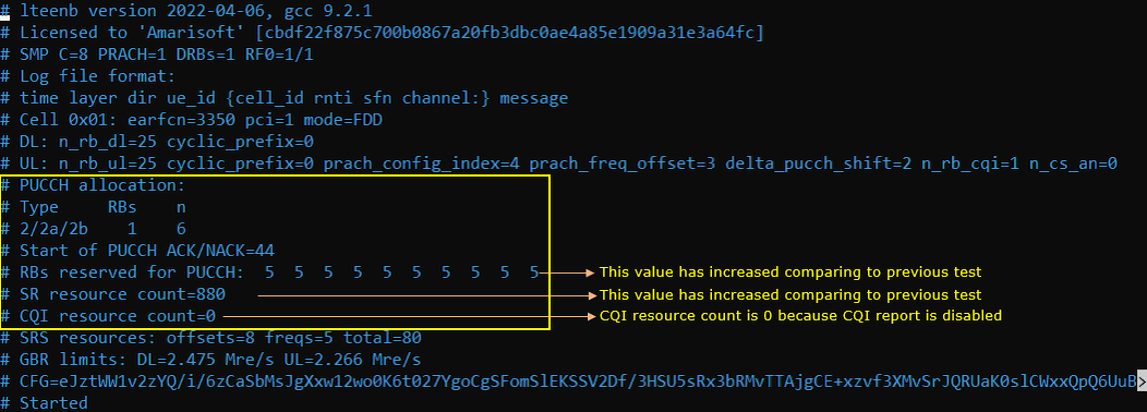
For the analysis of PUCCH log, it would be helpful to check first the meta data in the log file and check the overall information about PUCCH resource allocation. If you open up the enb log in text editor, you will find these information at the beginning of the log.
Compare the configuration value shown here with the value in previous test to see how the parameters set in the configuration file is reflected into actual pucch physical resources.
Check out pucch-ConfigCommon in SIB2 and see if the configuration parameter is properly reflected in the message. cqi_pucch_n_rb in configuration file is mapped to nRB-CQI IE in SIB2 and n1_pucch_sr_count in configuration file is mapped to n1PUCCH-AN IE in SIB2.
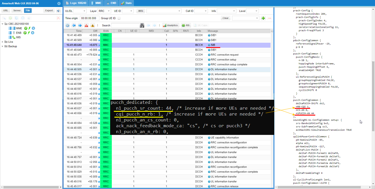
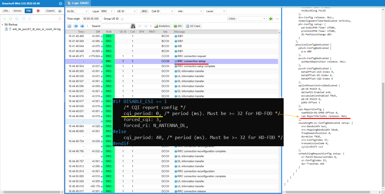
You can confirm that CQI is disabled from cqi-ReportConfig IE in RRC Connection Setup.
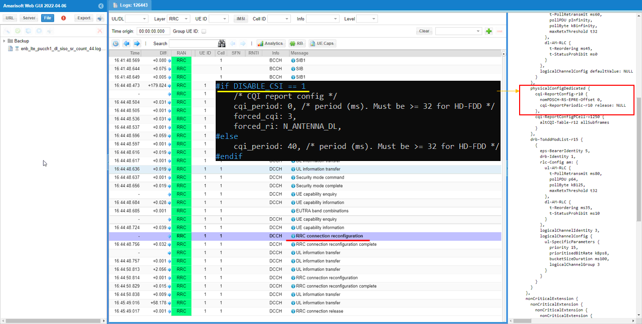
In additon, you can also confirm that CQI is enabled from phsicalConfigDedicated IE in RRC Connection Reconfiguration.
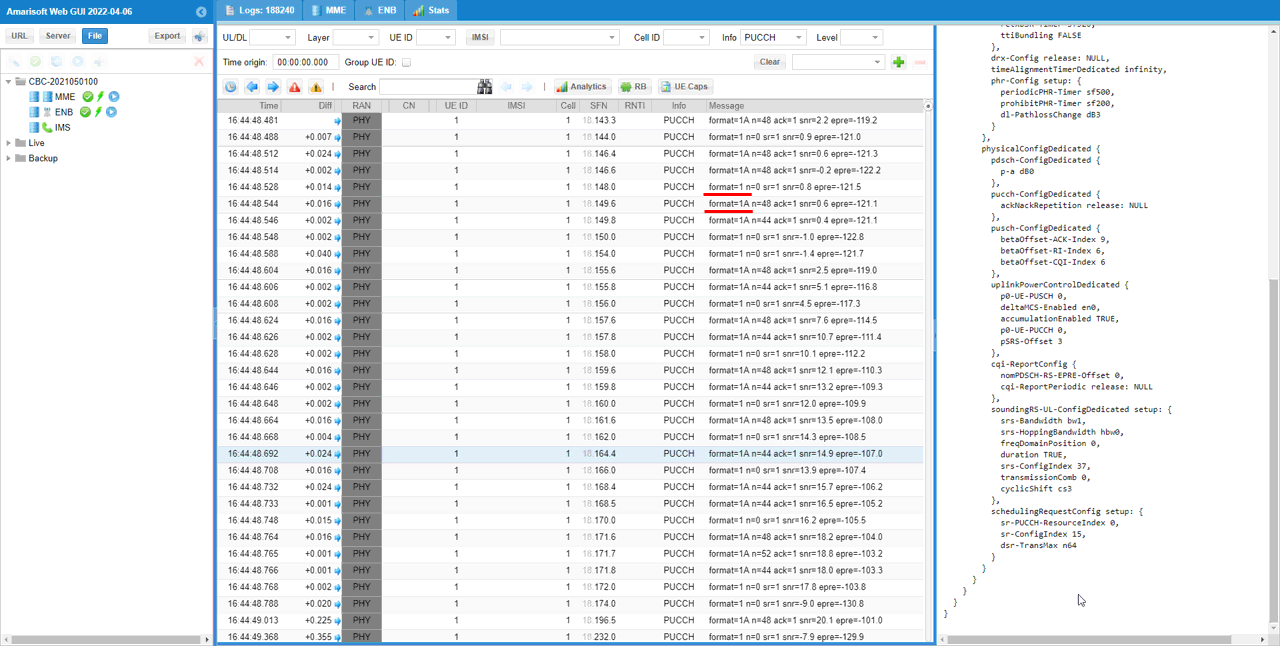
You can confirm with PHY log on which PUCCH formats are used for the test
If you check the time period while PDSCH is flowing in RB map, you can easily check out the Uplink physical resources that are really used by PUCCH. The small green rectangles in the lower track indicates the physical resources that are used by PUCCH.
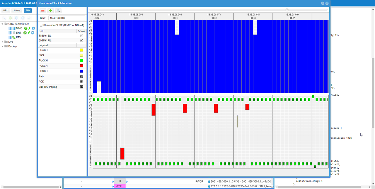
If you look into the period while PUSCH is fully allocated, you can visually confirm the physical resources reserved for PUCCH. The blank space outside of the red block(PUSCH) in lower track is the area reserved for PUCCH. This shows that Amarisoft does not allocate the reserved area for PUSCH even if it is not really used and this way of scheduling would give me a little bit lower maximum throughput than you may expected. If you want to schedule PUSCH even at the reserved area for maximum throughput, check out this tutorial.
Test 3 : SISO, CSI Enabled
This test is to show a case of the PUCCH configuration for SISO, CSI Enabled.
Configuration
I used the eNB configuration enb-pucch-dl-siso-csi.cfg which is copied from enb.default.cfg and modified for this tutorial.

I used the mme configuration mme-ims.cfg and ims configuration ims.default.cfg

In enb-pucch-dl-siso-csi.cfg , PUCCH related configurations are set as follows.
Set N_ANTENNA_DL 1 to configure the cell to SISO and set DISABLE_CSI 0 to enable CSI Report.

Configure n1_pucch_sr_count and cqi_pucch_n_rb in pucch_dedicated configuration to fit with the test configuration. In terms of efficient utilization of the physical resources, it is recommended not to set these unnecessarily large values.

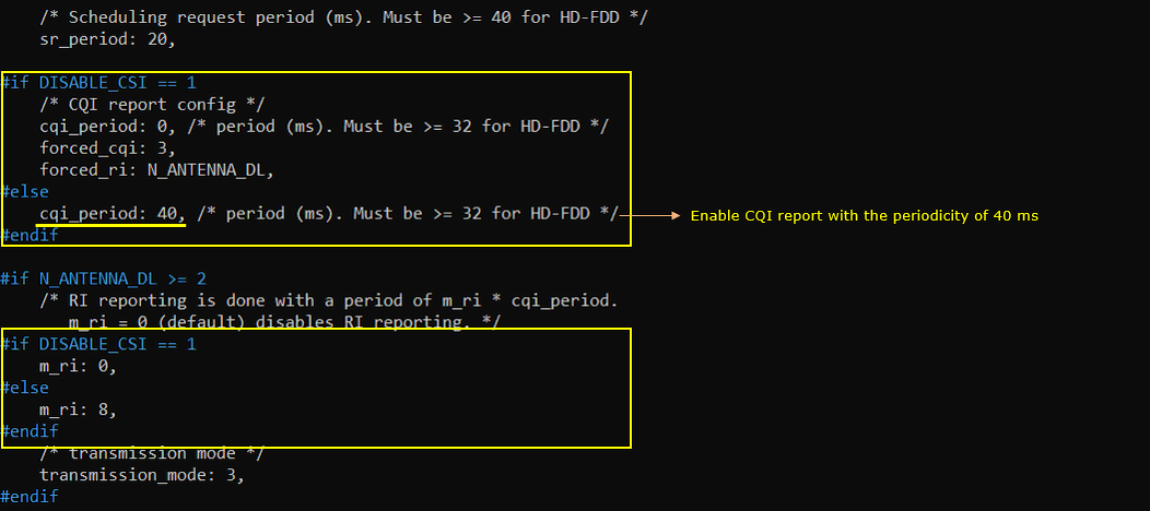
This is just to show how cqi_period, forced_cqi, force_ri, m_ri parameters are set depending on DISABLE_CSI value. This is only for informational purpose. you don't need to modify anything here.
Run and Check
Check the cell phy configuration and see if it is configured as intended.

run 't' command and power on UE and make it sure that UE complete the attach.
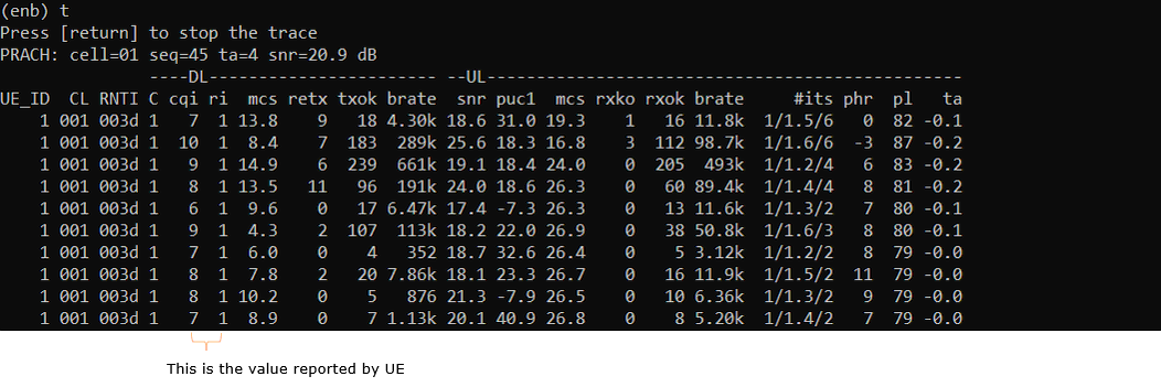
(This is not mandatory but) perform some high throughput test for both DL and UL. I ran a speedtest app on internet for this tutorial.
Log Analysis
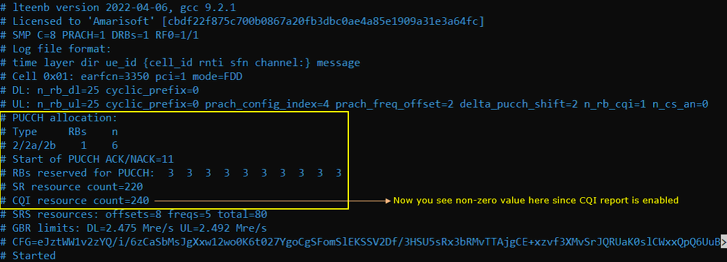
For the analysis of PUCCH log, it would be helpful to check first the meta data in the log file and check the overall information about PUCCH resource allocation. If you open up the enb log in text editor, you will find these information at the beginning of the log.
Compare the configuration value shown here with the value in previous test to see how the parameters set in the configuration file is reflected into actual pucch physical resources.
Check out pucch-ConfigCommon in SIB2 and see if the configuration parameter is properly reflected in the message. cqi_pucch_n_rb in configuration file is mapped to nRB-CQI IE in SIB2 and n1_pucch_sr_count in configuration file is mapped to n1PUCCH-AN IE in SIB2.
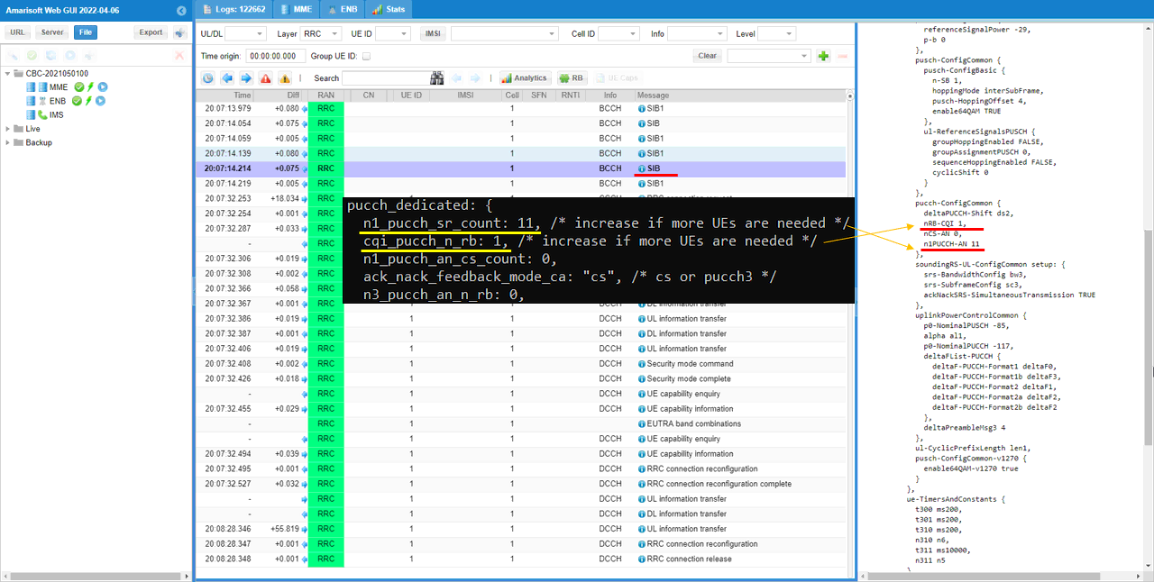
You can confirm that CQI is enabled from cqi-ReportConfig IE in RRC Connection Setup.
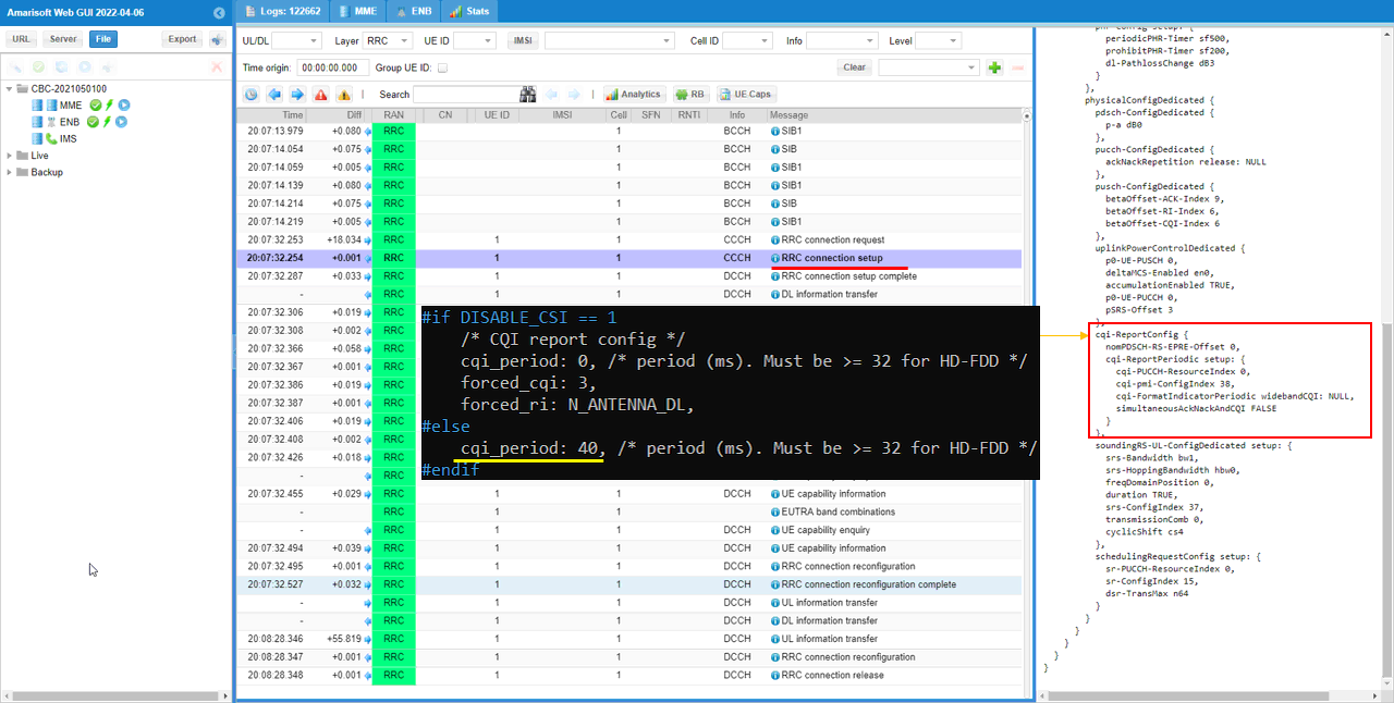
In additon, you can also confirm that CQI is enabled from phsicalConfigDedicated IE in RRC Connection Reconfiguration.
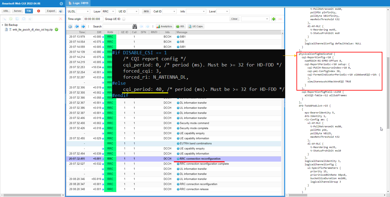
You can confirm with PHY log on which PUCCH formats are used for the test
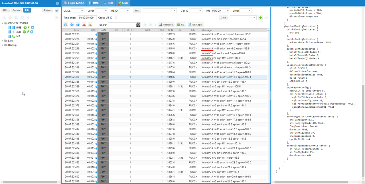
If you check the time period while PDSCH is flowing in RB map, you can easily check out the Uplink physical resources that are really used by PUCCH. The small green rectangles in the lower track indicates the physical resources that are used by PUCCH.
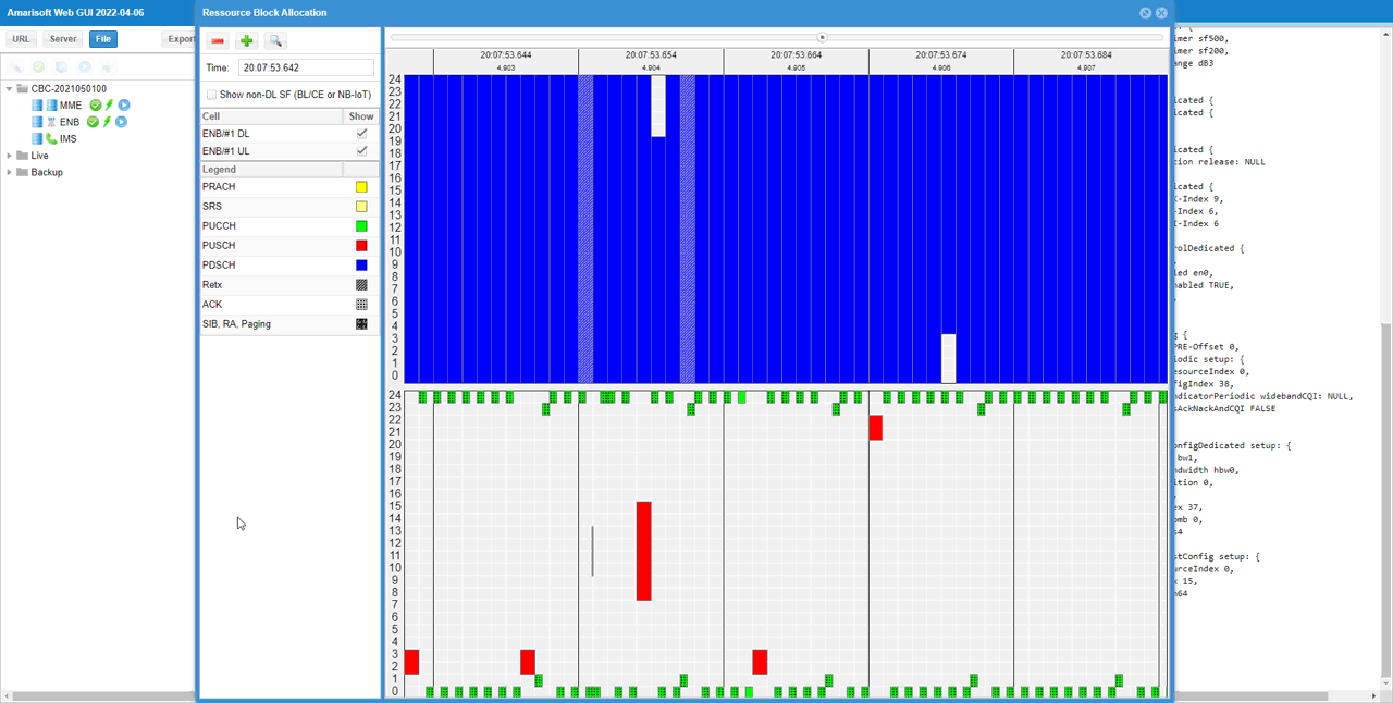
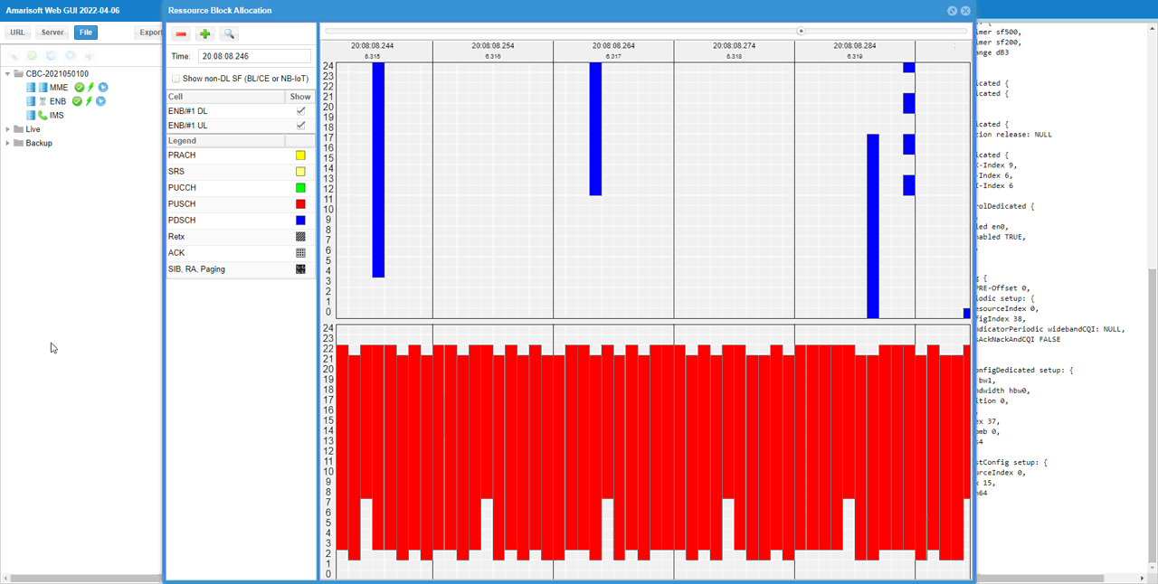
If you look into the period while PUSCH is fully allocated, you can visually confirm the physical resources reserved for PUCCH. The blank space outside of the red block(PUSCH) in lower track is the area reserved for PUCCH. This shows that Amarisoft does not allocate the reserved area for PUSCH even if it is not really used and this way of scheduling would give me a little bit lower maximum throughput than you may expected. If you want to schedule PUSCH even at the reserved area for maximum throughput, check out this tutorial.
Test 4 : SISO, CSI Enabled : nRB-CQI
This test is to show a case of the PUCCH configuration for SISO, CSI Enabled. In this test, I will show you how to change the RRC parameter nRB-CQI in configuration file.
Configuration
I used the eNB configuration enb-pucch-dl-siso-csi-nrbCQI.cfg which is copied from enb.default.cfg and modified for this tutorial.

I used the mme configuration mme-ims.cfg and ims configuration ims.default.cfg

In enb-pucch-dl-siso-csi-nrbCQI.cfg , PUCCH related configurations are set as follows.
Set N_ANTENNA_DL 1 to configure the cell to SISO and set DISABLE_CSI 0 to enable CSI Report.

Configure n1_pucch_sr_count and cqi_pucch_n_rb in pucch_dedicated configuration to fit with the test configuration. In terms of efficient utilization of the physical resources, it is recommended not to set these unnecessarily large values.

This is just to show how cqi_period, forced_cqi, force_ri, m_ri parameters are set depending on DISABLE_CSI value. This is only for informational purpose. you don't need to modify anything here.

Run and Check
Check the cell phy configuration and see if it is configured as intended.

run 't' command and power on UE and make it sure that UE complete the attach.

(This is not mandatory but) perform some high throughput test for both DL and UL. I ran a speedtest app on internet for this tutorial.
Log Analysis
For the analysis of PUCCH log, it would be helpful to check first the meta data in the log file and check the overall information about PUCCH resource allocation. If you open up the enb log in text editor, you will find these information at the beginning of the log.
Compare the configuration value shown here with the value in previous test to see how the parameters set in the configuration file is reflected into actual pucch physical resources.
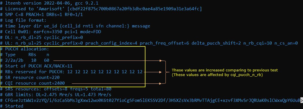
Check out pucch-ConfigCommon in SIB2 and see if the configuration parameter is properly reflected in the message. cqi_pucch_n_rb in configuration file is mapped to nRB-CQI IE in SIB2 and n1_pucch_sr_count in configuration file is mapped to n1PUCCH-AN IE in SIB2.
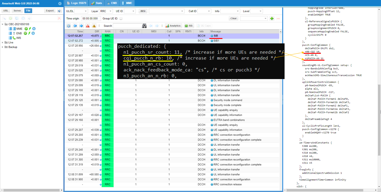
You can confirm that CQI is enabled from cqi-ReportConfig IE in RRC Connection Setup.
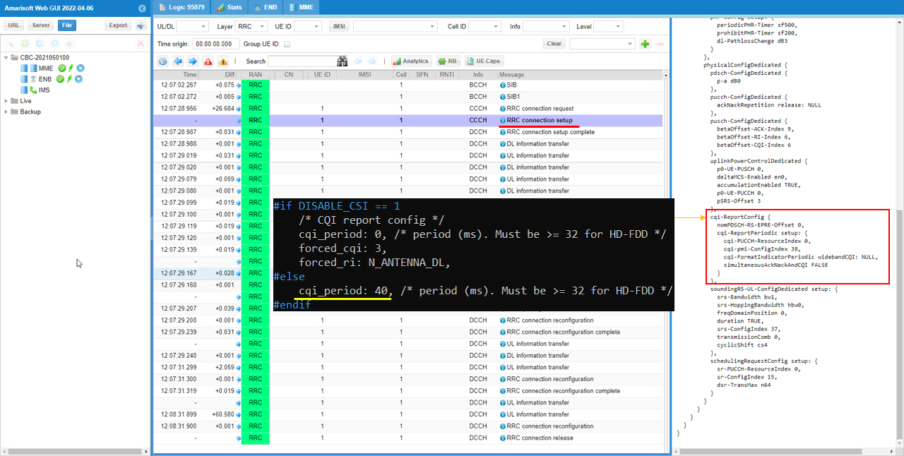
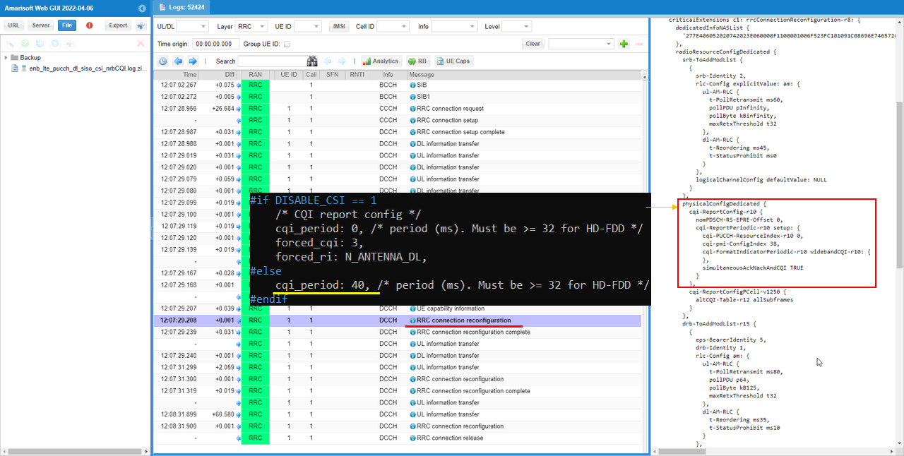
In additon, you can also confirm that CQI is enabled from phsicalConfigDedicated IE in RRC Connection Reconfiguration.
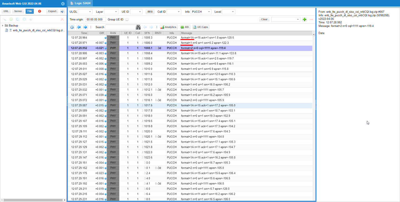
You can confirm with PHY log on which PUCCH formats are used for the test
If you check the time period while PDSCH is flowing in RB map, you can easily check out the Uplink physical resources that are really used by PUCCH. The small green rectangles in the lower track indicates the physical resources that are used by PUCCH.
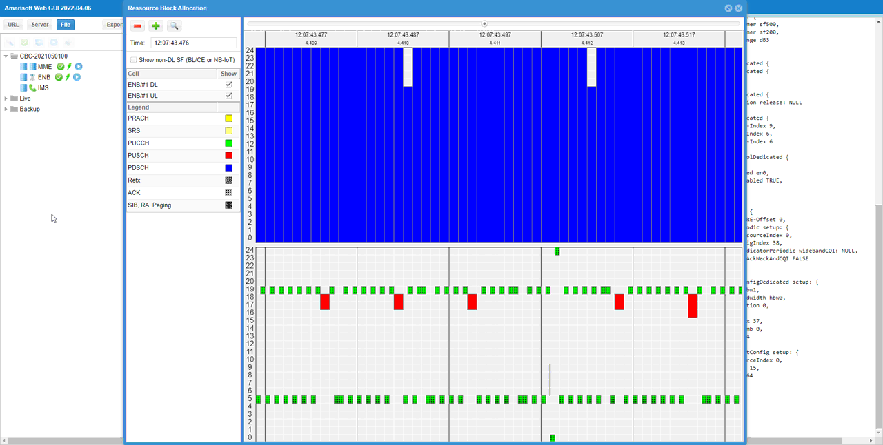
If you look into the period while PUSCH is fully allocated, you can visually confirm the physical resources reserved for PUCCH. The blank space outside of the red block(PUSCH) in lower track is the area reserved for PUCCH. This shows that Amarisoft does not allocate the reserved area for PUSCH even if it is not really used and this way of scheduling would give me a little bit lower maximum throughput than you may expected. If you want to schedule PUSCH even at the reserved area for maximum throughput, check out this tutorial.
Test 5 : MIMO, CSI Enabled
This test is to show a case of the PUCCH configuration for MIMO, CSI enabled.
Configuration
I used the eNB configuration enb-pucch-dl-mimo-csi.cfg which is copied from enb.default.cfg and modified for this tutorial.

I used the mme configuration mme-ims.cfg and ims configuration ims.default.cfg

In enb-pucch-dl-mimo-csi.cfg , PUCCH related configurations are set as follows.
Set N_ANTENNA_DL 1 to configure the cell to SISO and set DISABLE_CSI 0 to enable CSI Report.

Configure n1_pucch_sr_count and cqi_pucch_n_rb in pucch_dedicated configuration to fit with the test configuration. In terms of efficient utilization of the physical resources, it is recommended not to set these unnecessarily large values.

This is just to show how cqi_period, forced_cqi, force_ri, m_ri parameters are set depending on DISABLE_CSI value. This is only for informational purpose. you don't need to modify anything here.
Run and Check
Check the cell phy configuration and see if it is configured as intended.

run 't' command and power on UE and make it sure that UE complete the attach.

(This is not mandatory but) perform some high throughput test for both DL and UL. I ran a speedtest app on internet for this tutorial.
Log Analysis
For the analysis of PUCCH log, it would be helpful to check first the meta data in the log file and check the overall information about PUCCH resource allocation. If you open up the enb log in text editor, you will find these information at the beginning of the log.
Compare the configuration value shown here with the value in previous test to see how the parameters set in the configuration file is reflected into actual pucch physical resources.
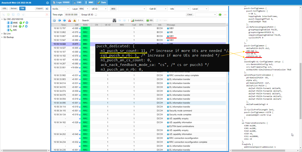
Check out pucch-ConfigCommon in SIB2 and see if the configuration parameter is properly reflected in the message. cqi_pucch_n_rb in configuration file is mapped to nRB-CQI IE in SIB2 and n1_pucch_sr_count in configuration file is mapped to n1PUCCH-AN IE in SIB2.
You can confirm that CQI is enabled from cqi-ReportConfig IE in RRC Connection Setup.
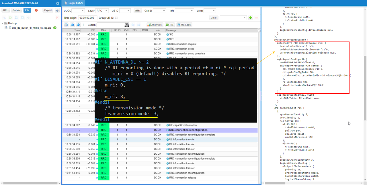
In additon, you can also confirm that CQI is enabled from phsicalConfigDedicated IE in RRC Connection Reconfiguration.
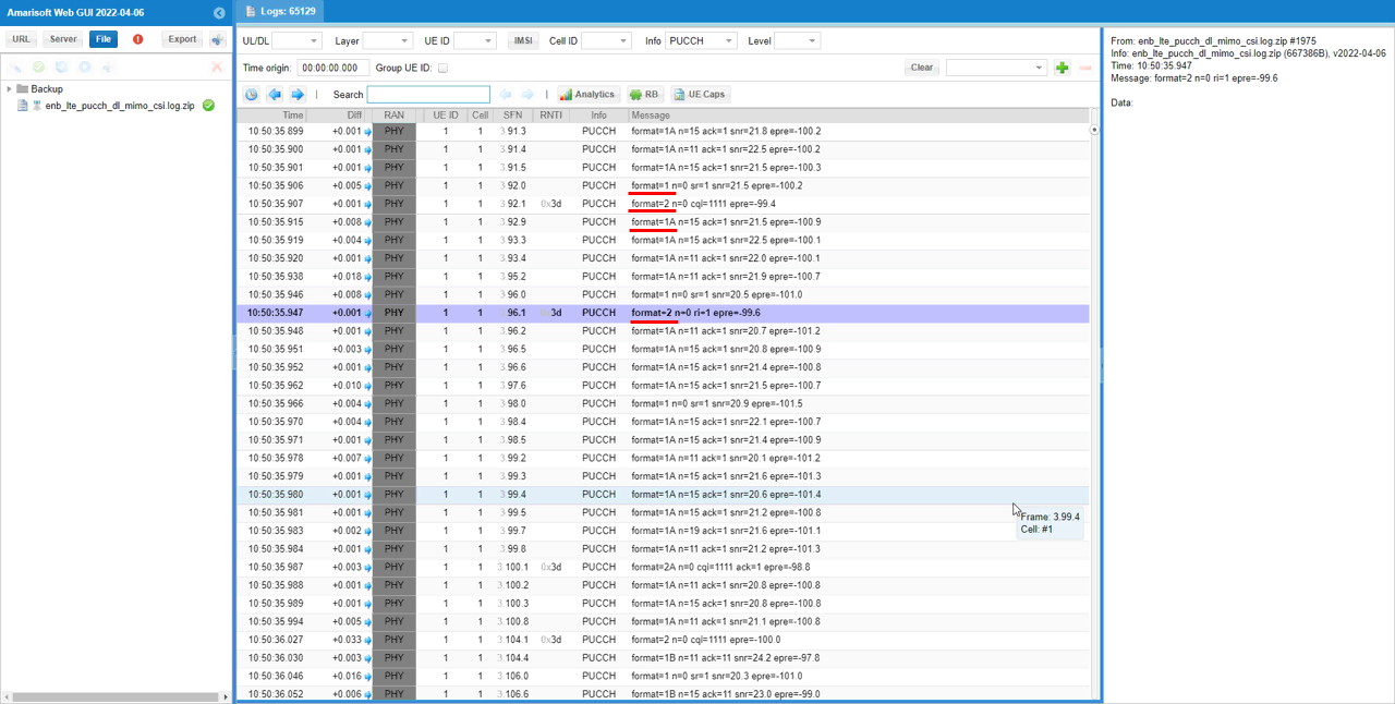
You can confirm with PHY log on which PUCCH formats are used for the test
If you check the time period while PDSCH is flowing in RB map, you can easily check out the Uplink physical resources that are really used by PUCCH. The small green rectangles in the lower track indicates the physical resources that are used by PUCCH.
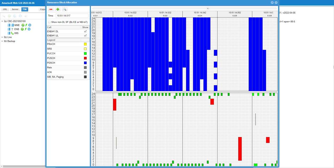
If you look into the period while PUSCH is fully allocated, you can visually confirm the physical resources reserved for PUCCH. The blank space outside of the red block(PUSCH) in lower track is the area reserved for PUCCH. This shows that Amarisoft does not allocate the reserved area for PUSCH even if it is not really used and this way of scheduling would give me a little bit lower maximum throughput than you may expected. If you want to schedule PUSCH even at the reserved area for maximum throughput, check out this tutorial.
Test 6 : Simulteneous CSI and Ack/Nack
This test is to show a case of the PUCCH configuration for SISO with Simultaneous CSI and Ack/Nack.
Configuration
I used the eNB configuration enb-pucch-dl-siso-csi-an-mux.cfg which is copied from enb.default.cfg and modified for this tutorial.

I used the mme configuration mme-ims.cfg and ims configuration ims.default.cfg

In enb-pucch-dl-siso-csi-an-mux.cfg , PUCCH related configurations are set as follows.
Set N_ANTENNA_DL 1 to configure the cell to SISO and set DISABLE_CSI 0 to enable CSI Report.

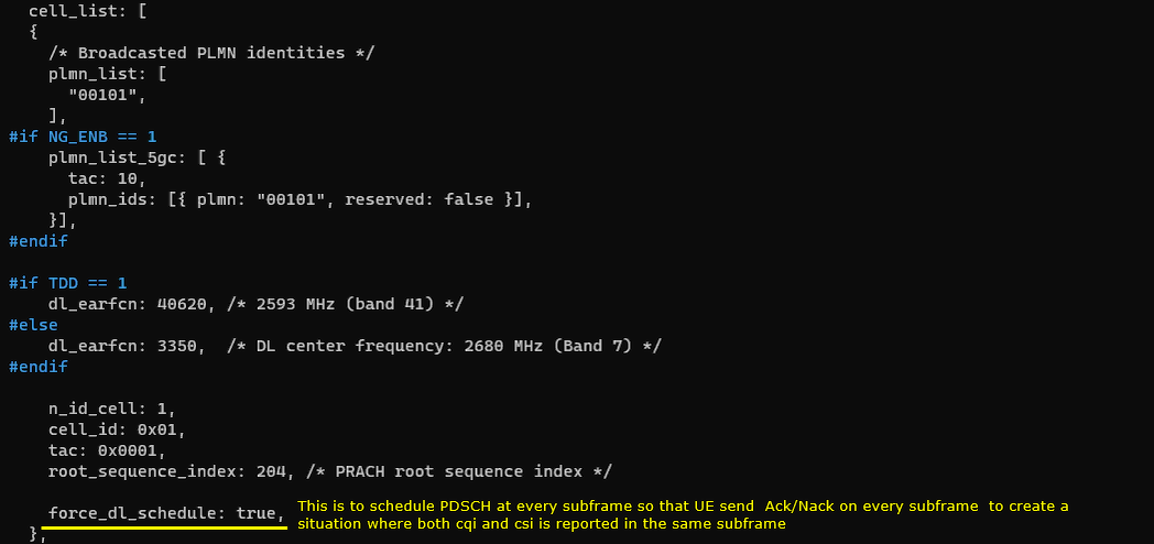
Just for testing purpose, I set force_dl_schedule: true. This is to schedule PDSCH at every subframe so that UE send Ack/Nack on every subframe to create a situation where both cqi and csi is reported in the same subframe.
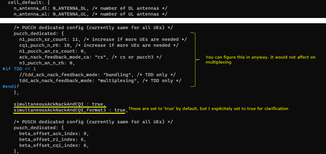
Set simultaneousAckNackAndCQI: true and simultaneousAckNackAndCQI_format3:true. In this case, you don't need to care about the parameters in pucch_dedicated configuration since they would not affect on multiplexing.
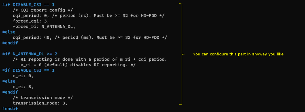
This is just to show how cqi_period, forced_cqi, force_ri, m_ri parameters are set depending on DISABLE_CSI value. This is only for informational purpose. you don't need to modify anything here.
Run and Check
Check the cell phy configuration and see if it is configured as intended.

run 't' command and power on UE and make it sure that UE complete the attach.

(This is not mandatory but) perform some high throughput test for both DL and UL. I ran a speedtest app on internet for this tutorial.
Log Analysis
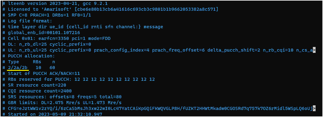
For the analysis of PUCCH log, it would be helpful to check first the meta data in the log file and check the overall information about PUCCH resource allocation. If you open up the enb log in text editor, you will find these information at the beginning of the log.
Compare the configuration value shown here with the value in previous test to see how the parameters set in the configuration file is reflected into actual pucch physical resources.
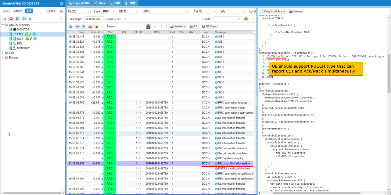
Confirm that UE support the PUCCH type that can report CSI and Ack/Nack simultaneously from featureGroupIndicators (FGI) in UE capability Information message
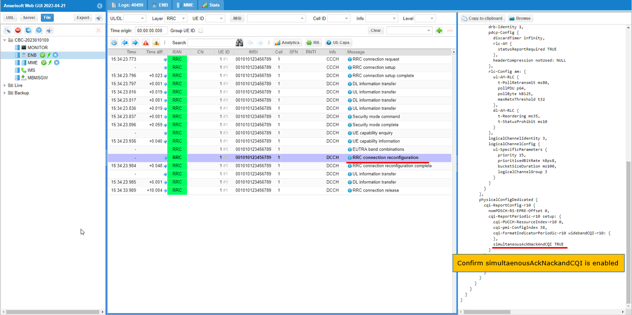
You can confirm that simultaneousAckNackAndCQI is enabled by checking out physicalConfigDedicated IE in RRC Connection reconfiguration message
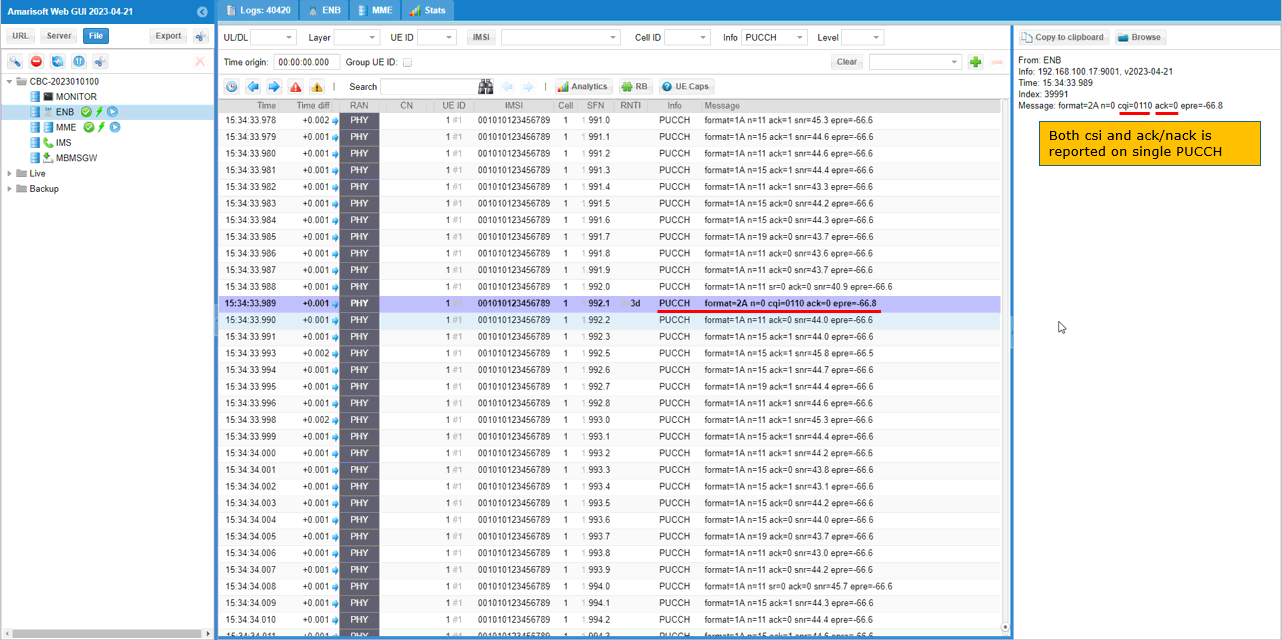
You can confirm with PHY log on which PUCCH formats are used for the test
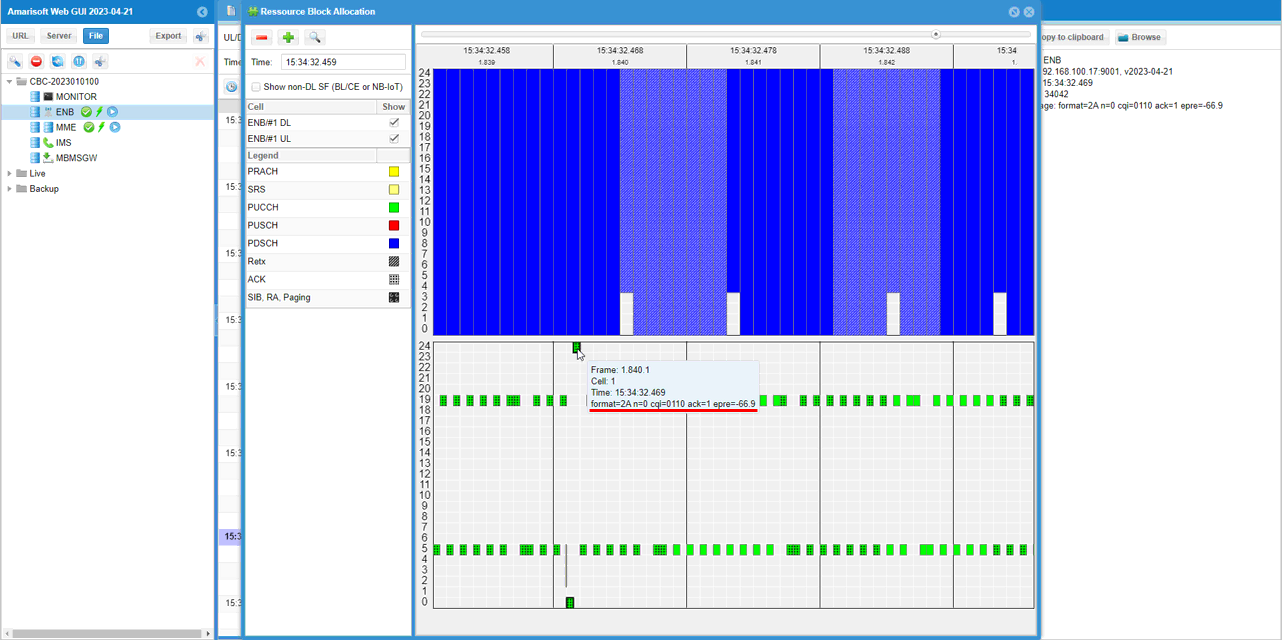
If you check the time period while PDSCH is flowing in RB map, you can easily check out the Uplink physical resources that are really used by PUCCH. The small green rectangles in the lower track indicates the physical resources that are used by PUCCH.
Test 7 : SIB2 ASN.1 Modification : nCS-AN change
This test is to show how to change a PUCCH configuration not cofigurable in configuration file by modifying SIB2 message.
Configuration
I used the eNB configuration enb-pucch-dl-siso-csi-nCS-AN.cfg which is copied from enb.default.cfg and modified for this tutorial. And in this tutorial, the modified SIB ASN.1 is used. sib2_3_nCS-AN.asn is copied and modified from sib2_3.asn.
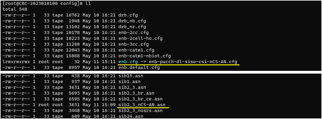
I used the mme configuration mme-ims.cfg and ims configuration ims.default.cfg

In enb-pucch-dl-siso-csi-nCS-AN.cfg , PUCCH related configurations are set as follows.
Set N_ANTENNA_DL 1 to configure the cell to SISO and set DISABLE_CSI 0 to enable CSI Report.

Just for testing purpose, I set force_dl_schedule: true. This is to schedule PDSCH at every subframe so that UE send Ack/Nack on every subframe to create a situation where both cqi and csi is reported in the same subframe.
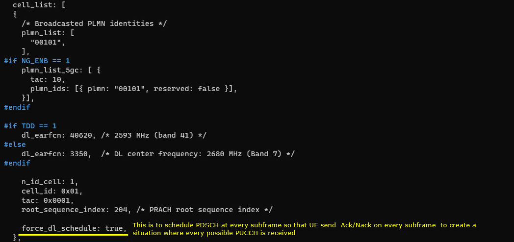
Specify the file name of the modified sib messages to filename in sib_sched_list configuration.

Set simultaneousAckNackAndCQI: true and simultaneousAckNackAndCQI_format3:true. In this case, you don't need to care about the parameters in pucch_dedicated configuration since they would not affect on multiplexing.
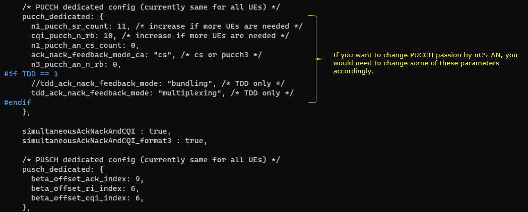
In this case, you don't need to care about the parameters in cqi_period, m_ri since they would not affect on multiplexing.
In sib2_3_nCS-AN.asn , nCS-AN value of pucch-ConfigCommon IE of SIB2 is changed in this test.

Run and Check
Check the cell phy configuration and see if it is configured as intended.

run 't' command and power on UE and make it sure that UE complete the attach.

(This is not mandatory but) perform some high throughput test for both DL and UL. I ran a speedtest app on internet for this tutorial.
Log Analysis
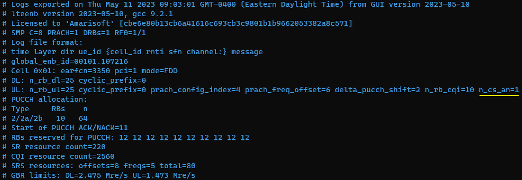
For the analysis of PUCCH log, it would be helpful to check first the meta data in the log file and check the overall information about PUCCH resource allocation. If you open up the enb log in text editor, you will find these information at the beginning of the log.
Compare the configuration value shown here with the value in previous test to see how the parameters set in the configuration file is reflected into actual pucch physical resources.
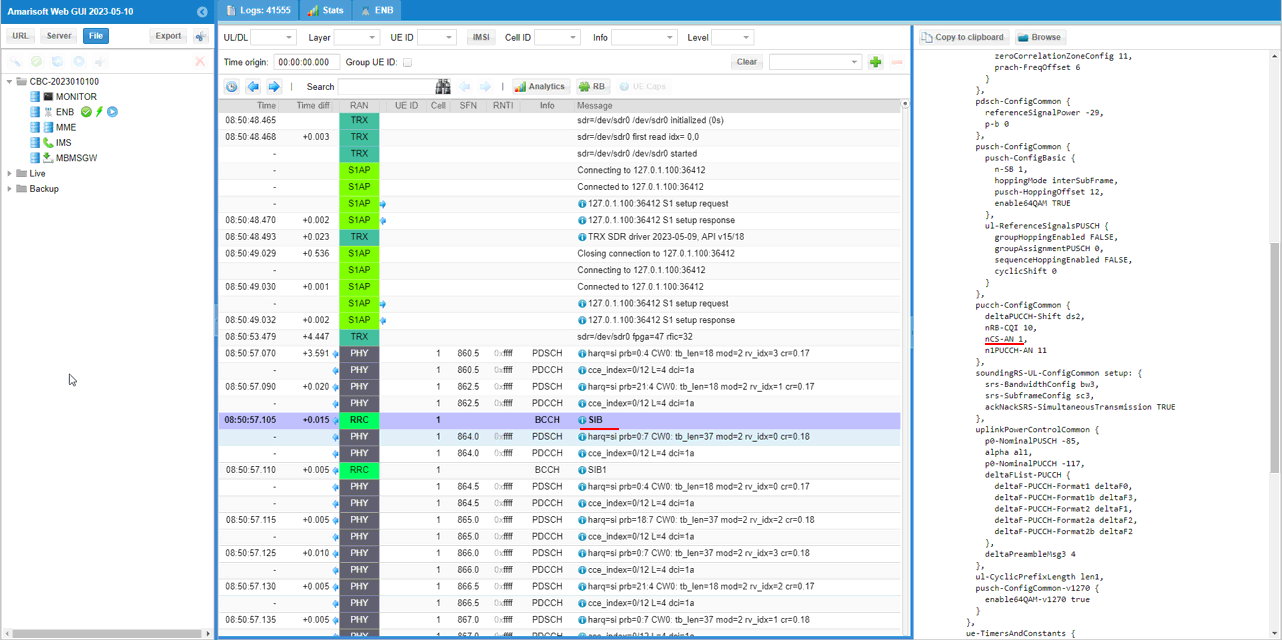
Check out pucch-ConfigCommon in SIB2 and see if the configuration parameter is properly reflected in the message. Check nCS-AN IE is set as you configured in sib2 asn file.
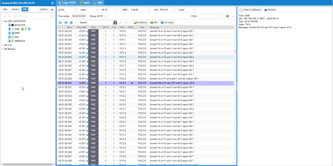
You can confirm with PHY log on which PUCCH formats are used for the test
If you check the time period while PDSCH is flowing in RB map, you can easily check out the Uplink physical resources that are really used by PUCCH. The small green rectangles in the lower track indicates the physical resources that are used by PUCCH.
RRC / NAS Signaling
SIB 2
: This is the SIB 2 message sent by eNB to configure LTE PUCCH. (
{
message c1: systemInformation: {
criticalExtensions systemInformation-r8: {
sib-TypeAndInfo {
sib2: {
radioResourceConfigCommon {
rach-ConfigCommon {
...
},
bcch-Config {
...
},
pcch-Config {
...
},
prach-Config {
...
},
pdsch-ConfigCommon {
...
},
pusch-ConfigCommon {
...
},
pucch-ConfigCommon {
deltaPUCCH-Shift ds2,
nRB-CQI 1,
nCS-AN 0,
n1PUCCH-AN 11
},
soundingRS-UL-ConfigCommon setup: {
...
},
uplinkPowerControlCommon {
...
},
ul-CyclicPrefixLength len1,
pusch-ConfigCommon-v1270 {
...
}
},
ue-TimersAndConstants {
...
},
...
},