
LTE HO(Handover) - Inter Frequency
This tutorial shows how to test LTE to LTE Handover in Inter Frequency with a commercial phone. This tutorial also shows how to configure Measurement Report and how to trigger measurement report. Triggering measurement report for inter frequency on Amari callbox is a little bit trickier than intra frequency case because of triggering measurement gap. Handover is a procedure of cell change during the connected mode and usually occurs as described below.
Step 1 : Network (eNB) configures measurement request to direct UE to perform the measurement of current cell and neighbouring cells
Step 2 : UE perform the measurement and send the report to the network if the measurement result matches the condition set by the measurement request configuration specified at step 1
Step 3 : Network sends RRC message to force UE to change cell (Handover) to the target cell. In this RRC message, network sends all the necessary low layer information about the target cell (e.g, cell frequency, rach info and other channel information)
In terms of frequencies of current cell and target/destination cell, the handover can be categorized into two types as below
- Intra Frequency Handover : Current Cell and Target Cell frequency is same
- Inter Frequency Handover : Current Cell and Target Cell frequency is different
Table of Contents
- LTE HO(Handover) - Inter Frequency
Introduction
LTE (Long Term Evolution) is a cornerstone of modern wireless communication, enabling high-speed data transmission and robust connectivity for mobile devices. One of the critical features of LTE networks is the seamless handover process, which ensures uninterrupted service as User Equipment (UE), such as commercial smartphones, move between different cells or frequencies. Handover procedures are vital for maintaining call quality and data integrity, particularly in dense urban environments or scenarios with significant mobility. Inter Frequency Handover, in particular, involves transitioning a connection from one frequency band to another, which is more complex than intra frequency handover due to the need for measurement gaps and more sophisticated radio resource management. The LTE handover mechanism relies on a collaborative interaction between the network's base stations (eNodeBs) and the UE. The process typically starts with the configuration of measurement reports, enabling the UE to assess the quality of surrounding cells. Upon meeting specific criteria, the UE triggers a measurement report to the network, allowing the eNodeB to make informed decisions about when and where to initiate the handover. Tools such as the Amari Callbox provide a controlled environment to simulate and test these scenarios, supporting both measurement-based and blind handover strategies. Understanding and validating the inter frequency handover process is essential for network engineers and testers to ensure optimal performance and user experience in live LTE deployments.
-
Context of LTE to LTE Inter Frequency Handover
- LTE technology employs advanced radio resource management to maintain connectivity as UEs move across coverage areas.
- Inter Frequency Handover is employed when the serving and target eNodeBs operate on different frequency bands, often due to load balancing, interference management, or coverage optimization.
- Measurement configuration and reporting are fundamental to enabling the network to make accurate handover decisions based on real-time radio conditions.
- Test environments like Amari Callbox replicate network scenarios, allowing controlled, repeatable handover testing with commercial devices.
-
Relevance and Importance of the Tutorial
- Understanding inter frequency handover is crucial for maintaining seamless mobility and high service quality in LTE networks.
- Proper configuration and triggering of measurement reports are essential for ensuring that handovers are executed efficiently and reliably.
- This tutorial addresses the complexities unique to inter frequency scenarios, such as the necessity for measurement gaps.
- Insights gained from this tutorial aid in troubleshooting, optimizing, and validating LTE networks in both lab and live environments.
-
Learning Outcomes
- Comprehend the LTE handover architecture and the sequence of events in inter frequency handover.
- Gain practical experience configuring and testing measurement reports and handover triggers using commercial smartphones.
- Understand the differences between measurement-based and blind handover approaches and how to implement each using test equipment.
- Acquire skills for diagnosing handover issues and optimizing LTE network performance.
-
Prerequisite Knowledge and Skills
- Basic understanding of LTE network architecture, including the roles of eNodeB and UE.
- Familiarity with radio resource management concepts and mobility procedures in cellular networks.
- Experience with test tools such as the Amari Callbox is beneficial, though key steps will be explained in the tutorial.
- General knowledge of wireless communication fundamentals and protocol workflows will enhance comprehension.
Summary of the Tutorial
This tutorial describes the procedure for performing and validating an LTE Inter-Cell Handover test using a callbox and two SDR-based eNBs. The focus is on the practical setup, configuration, execution, and verification of inter-cell handover between two LTE cells operating on different frequencies.
-
Test Setup:
- SIM card provided with the system is used.
- Reference is made to a configuration guide for custom SIM or system settings.
- Test environment includes two LTE cells with separate configurations for inter-cell handover.
-
Key Configuration Parameters:
- ncell_list: Configure neighbor cell lists for each cell, ensuring each cell recognizes the other as a neighbor with a different frequency (dl_earfcn).
- meas_config_desc: Set up measurement event criteria (such as a1, a2, a3 events, thresholds, hysteresis, and time to trigger) to define when measurement reports should be generated for handover triggering.
- meas_gap_config: Configure measurement gaps as required for inter-frequency measurement reporting.
- ho_from_meas: Define handover trigger logic based on reported measurements.
-
Configuration Process:
- Modify and use enb-2cell-ho-inter.cfg to enable handover between two cells, ensuring N_CELL is set to at least 2.
- For each eNB, configure ncell_list to add the other cell as a neighbor with a different frequency.
- Set up meas_config_desc to define handover measurement criteria and events.
- Ensure measurement gap and handover logic configurations are in place based on Amarisoft documentation.
-
Test Execution Steps:
- Start the LTE service and confirm both cell configurations are active.
- Adjust the output power of cells using cell_gain commands to ensure the UE initially camps on the first cell.
- Power on the UE and let it attach to the first cell.
- Modify cell power so that the target cell becomes stronger than the current camping cell, triggering a measurement report as per the configured criteria.
- Observe and confirm that handover is triggered and completed properly; adjust cell powers as necessary to ensure the handover occurs.
-
Log Analysis Steps:
- Verify that measurement report configurations (measObjectToAddModList, reportConfigToAddModList, measIdToAddModList) are set as intended during UE attach.
- Check that measGapConfig is initially set to Release and is setup when measurement gap criteria are met.
- Confirm that UE sends the required measurement report when cell power conditions meet the trigger criteria.
- Validate that the eNB triggers handover upon receiving the proper measurement report, and that the handover parameters (such as targetPhysCellId) are correct.
- If handover is not triggered, tweak cell powers or measurement criteria accordingly.
Note: The tutorial emphasizes careful configuration of measurement and neighbor cell parameters, validation through log analysis, and iterative adjustment of test parameters (such as cell power) to ensure proper handover triggering and completion. For details on specific configuration fields, refer to Amarisoft documentation as linked in the tutorial.
Test Setup
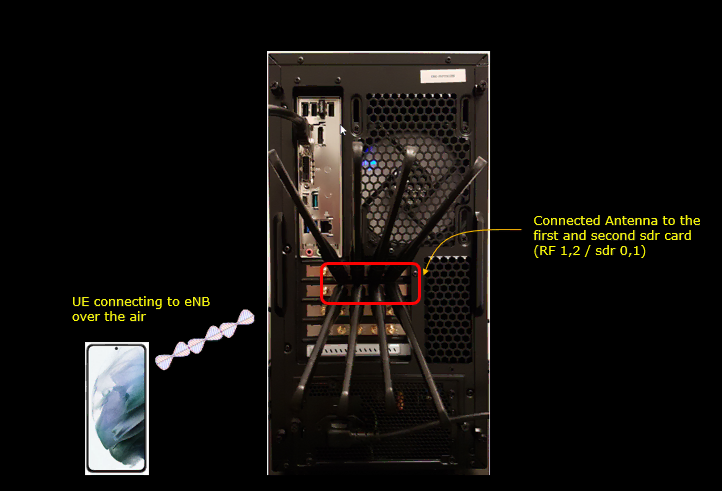
Test setup for this tutorial is as shown below.
- SIM Card used in this tutorial is the one delivered with the system as it is.
- If you want to change the configuration, The tutorial Configuration Guide would help
Key Configuration Parameters
Followings are important configuration parameters for this tutorial. You may click on the items for the descriptions from Amarisoft documents.
- ncell_list : In this link, you would get the descriptions for all the items listed below
- rat
- cell_id
- meas_config_desc : In this link, you would get the descriptions for all the items listed below
- a1_report_type
- a1_rsrp
- a1_hysteresis
- a1_time_to_trigger
- a2_report_type
- a2_hysteresis
- a2_time_to_trigger
- a3_report_type
- a3_offset
- a3_hysteresis
- a3_time_to_trigger
- meas_gap_config
- ho_from_meas
Configuration
I used the enb-2cell-ho-inter.cfg which is copied and modified from enb-2cell-ho.cfg.
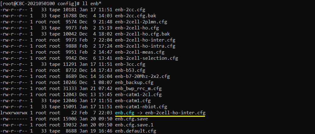
I also used mme-ims.cfg as it is.

Configure enb-2cell-ho-inter.cfg as below.
In this test, N_CELL is set to 2 because inter-frequency handover requires at least two cells: one serving cell and one target cell. TDD is set to 0, meaning this example uses FDD mode. N_RB_DL is set to 25, which corresponds to 5 MHz bandwidth. N_ANTENNA_DL and N_ANTENNA_UL are both set to 1, so this example uses SISO for both downlink and uplink. CHANNEL_SIM is set to 0, meaning the internal channel simulator is disabled. NG_ENB is set to 0 because this test is based on LTE eNB operation, not ng-eNB operation.

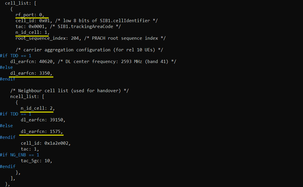
Add the neighbour cell list, ncell_list, to the first cell configuration and register the second cell as the neighbour cell by setting n_id_cell: 2. In this example, the first cell is the serving cell where the UE initially camps, and the second cell is the target cell for handover. Since this tutorial is for inter-frequency handover, the serving cell and target cell use different downlink EARFCNs. For FDD, the serving cell uses dl_earfcn: 3350, while the neighbour target cell uses dl_earfcn: 1575. This difference in dl_earfcn is the key point that makes this an inter-frequency handover case.
The neighbour cell entry also includes the target cell identity information such as cell_id and tac, which allows the eNB to identify the target cell and prepare the handover command properly. In short, this part of the configuration tells the serving cell which neighbour cell can be used as the handover target and on which frequency the UE should measure that target cell.
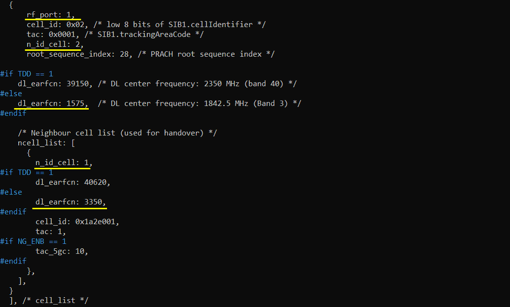
Add the neighbour cell list, ncell_list, to the second cell configuration and register the first cell as the neighbour cell by setting n_id_cell: 1. In this part of the test, the UE may be connected to the second cell, and the first cell becomes the target cell for handover. Since this is still an inter-frequency handover scenario, the second cell and the first cell are configured with different downlink EARFCNs. For FDD, the second cell uses dl_earfcn: 1575, while its neighbour target cell uses dl_earfcn: 3350.
This configuration makes the handover relationship bidirectional. The first cell already knows the second cell as a possible handover target, and now the second cell also knows the first cell as a possible handover target. This is useful when you want to test handover in both directions, from cell 1 to cell 2 and from cell 2 back to cell 1.
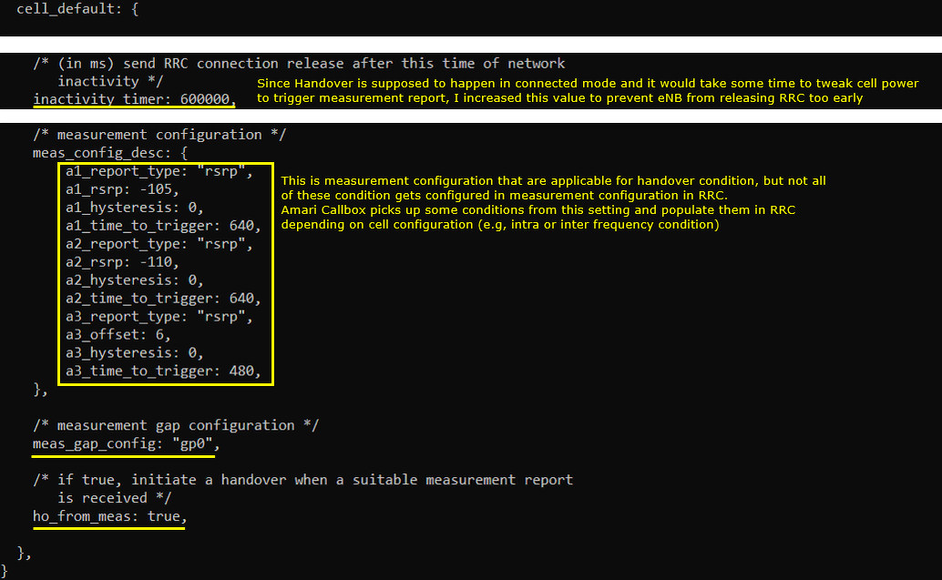
Then configure the measurement criteria in meas_config_desc so that the UE can send a Measurement Report before handover is triggered. Since handover happens in RRC connected mode and it may take some time to adjust the cell power until the measurement condition is satisfied, inactivity_timer is increased to 600000 to prevent the eNB from releasing the RRC connection too early.
The meas_config_desc section defines measurement event conditions that can be used for handover triggering. In this example, RSRP is used as the measurement quantity. a1_report_type: "rsrp" with a1_rsrp: -105 defines the A1 condition, which is usually used to indicate that the serving cell becomes better than a threshold. a2_report_type: "rsrp" with a2_rsrp: -110 defines the A2 condition, which is usually used to indicate that the serving cell becomes worse than a threshold. a3_report_type: "rsrp" with a3_offset: 6 defines the A3 condition, which is commonly used for handover because it means the neighbour cell becomes better than the serving cell by the configured offset. The time_to_trigger values define how long the condition should remain true before the UE sends the report.
For inter-frequency handover, meas_gap_config: "gp0" is important because the UE needs measurement gaps to measure the neighbour cell on a different frequency while it is still connected to the serving cell. Finally, ho_from_meas: true tells the eNB to initiate handover automatically when a suitable Measurement Report is received.
Perform the test
Start the LTE service and first check the basic cell configuration. The exact frequency and bandwidth can be different depending on your own test setup, but both cells should be shown as LTE cells and the two cells should have different downlink EARFCNs for this inter-frequency handover test.
In the cell phy output, cell 0x001 is configured as LTE Band 7 with 5 MHz bandwidth and DL EARFCN 3350, while cell 0x002 is configured as LTE Band 3 with 5 MHz bandwidth and DL EARFCN 1575. This confirms that the two LTE cells are running on different frequencies. The PCI values are also different, with PCI 1 for cell 0x001 and PCI 2 for cell 0x002, so the UE can distinguish the two cells during measurement.
The cell output gives a simpler view of the same configuration. Cell 0x001 uses n_id_cell 1, PRACH root sequence index 204, and DL gain 0.0. Cell 0x002 uses n_id_cell 2, PRACH root sequence index 28, and DL gain 0.0. At this point, the basic two-cell LTE configuration is ready, and you can proceed to UE attach and measurement-triggered handover testing.


Adjust the cell power before attaching the UE. In this step, the power of the second cell is lowered so that the UE camps on the first cell first. This is done with the cell_gain command by setting cell 1 to -10 dB and cell 2 to -20 dB. The exact gain values may need to be adjusted depending on the UE model, antenna placement, cable loss, and test environment, but the main purpose is to make cell 1 stronger than cell 2 at the beginning of the test.
After applying the command, the cell output shows dl_gain: -10.0 for cell 0x001 and dl_gain: -20.0 for cell 0x002, confirming that the second cell is configured weaker than the first cell. In this example, tx_gain is not changed and remains at the default value. cell_gain is used instead of tx_gain because tx_gain may change the broadcast reference cell power information in SIB, and that SIB change can affect UE behavior in a less predictable way during the test.


Power on the UE and let it attach to the network. After starting the trace with the t command, check the CL column to confirm which cell the UE is connected to. In this example, the UE is connected to cell 001, which means the initial cell selection worked as intended and the UE attached to the first cell.
The trace also shows PRACH activity on cell=01, meaning the UE performed random access toward cell 1. After attach, the UE traffic and radio status are displayed in the trace, including RNTI, CQI, MCS, bitrate, SNR, PUCCH power, PHR, path loss, and timing advance. At this point, the important check is not the exact value of each radio metric, but confirming that the UE is in connected mode on cell 1 before trying to trigger inter-frequency handover to cell 2.

Adjust the cell power to trigger the Measurement Report. In this step, the serving cell power is decreased and the target cell power is increased so that the target cell becomes stronger than the serving cell. Since the UE is currently connected to cell 1, cell 1 is weakened by setting dl_gain to -16.0, while cell 2 is made stronger by setting dl_gain to -10.0. This creates the radio condition required for the UE to satisfy the configured measurement event, such as the neighbour cell becoming better than the serving cell.
The exact gain values may be different depending on the UE and test environment, so you may need to tune them gradually. The main point is to make the serving cell weak enough and the target cell strong enough so that the UE sends the Measurement Report, which then allows the eNB to trigger handover to the target cell.

Confirm that the handover has completed properly by checking the trace again with the t command. In this example, the CL column has changed from 001 to 002, which means the UE is now connected to cell 2. This confirms that the UE measured the inter-frequency neighbour cell, sent the Measurement Report, and completed the handover from the serving cell to the target cell.
If the CL value does not change to 002, adjust the cell power again and wait until the measurement condition is satisfied. In practice, the proper gain setting depends on the UE, RF connection, antenna/cable environment, and measurement event thresholds, so the handover may not happen immediately with the first power setting.

Log Analysis
During the initial attach, check the RRC Connection Reconfiguration message sent from the Callbox to the UE. This message includes the measurement configuration that the UE will use later to decide when to send a Measurement Report. In the decoded message, confirm that measObjectToAddModList, reportConfigToAddModList, and measIdToAddModList are configured as intended.
measObjectToAddModList defines what frequency or cell the UE should measure. In this example, you should see measurement objects for the serving and neighbour LTE frequencies, such as carrierFreq 3350 and carrierFreq 1575. reportConfigToAddModList defines the reporting condition, such as A1, A2, or A3 event, the RSRP threshold or offset, hysteresis, timeToTrigger, triggerQuantity, reportQuantity, and reportInterval. measIdToAddModList connects the measurement object and report configuration together, so the UE knows which reporting rule should be applied to which measured frequency.
This step is important because the handover itself happens later, but the UE can only send the proper Measurement Report if this measurement configuration was already delivered correctly during RRC reconfiguration.
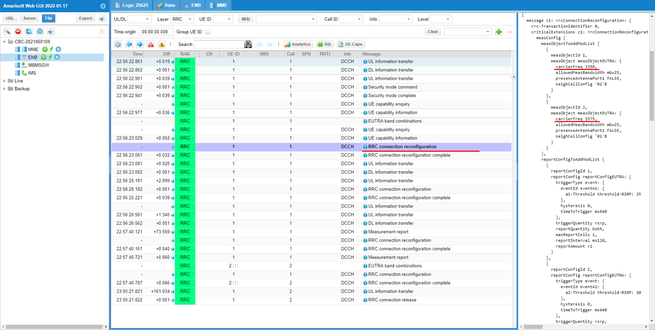
This can be normal in this test flow. Even though meas_gap_config: "gp0" is configured in the eNB configuration file, the eNB may not activate the measurement gap immediately during initial attach. The measurement gap can be enabled later when the proper measurement condition is reached, for example when the serving cell becomes weak enough or when the inter-frequency neighbour cell needs to be measured for handover decision. Therefore, if measGapConfig is still release in the initial RRC reconfiguration, it does not necessarily mean the configuration is wrong. It means the measurement gap has not been activated yet.
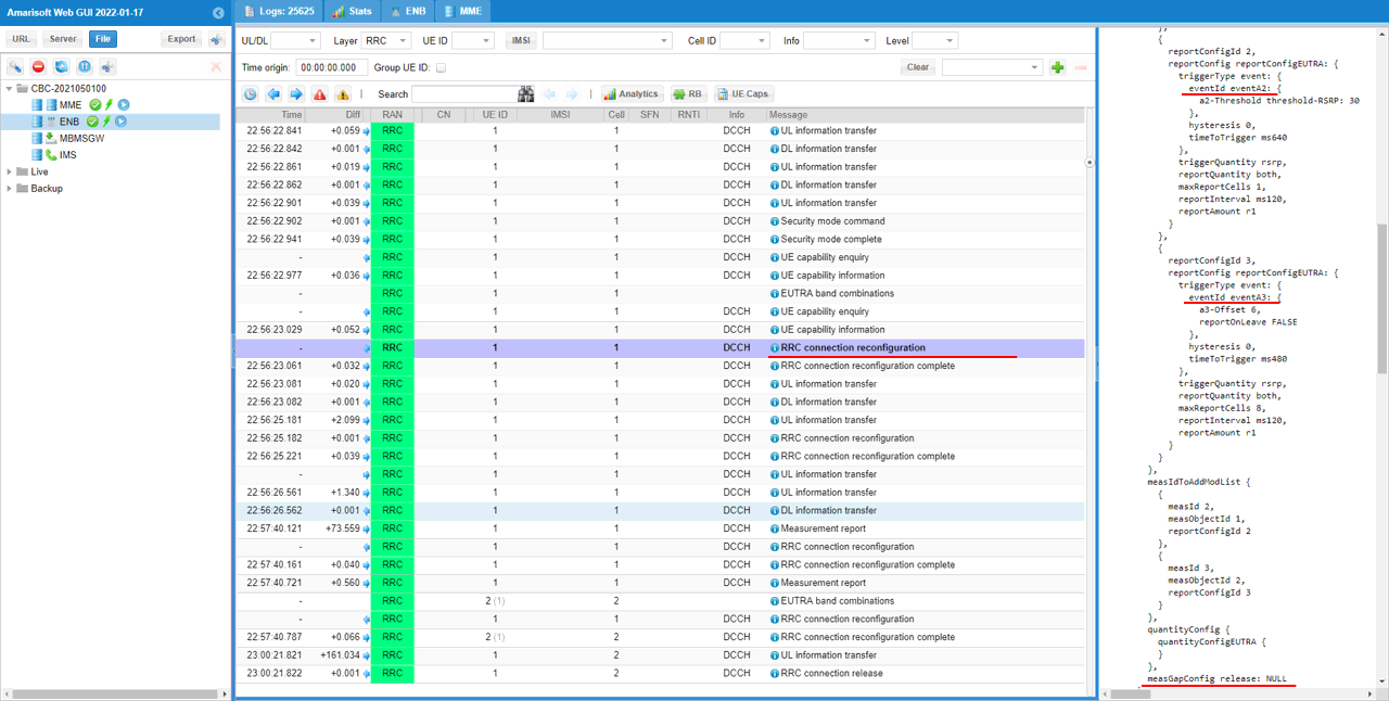
When the cell power condition satisfies the measurement gap activation criteria, the eNB sends another RRC Connection Reconfiguration message to enable the measurement gap. In this message, measGapConfig is changed from release to setup, which means the UE is now instructed to reserve periodic measurement gaps for inter-frequency measurement.
In the decoded message, measGapConfig setup includes gapOffset gp0: 0. This indicates that measurement gap pattern gp0 is activated with the specified gap offset. Once this is configured, the UE can temporarily stop serving-cell reception at the configured gap timing and measure the neighbour LTE frequency. This step is important for inter-frequency handover because the target cell is on a different EARFCN, so the UE needs measurement gaps before it can reliably evaluate the target cell and send the proper Measurement Report.

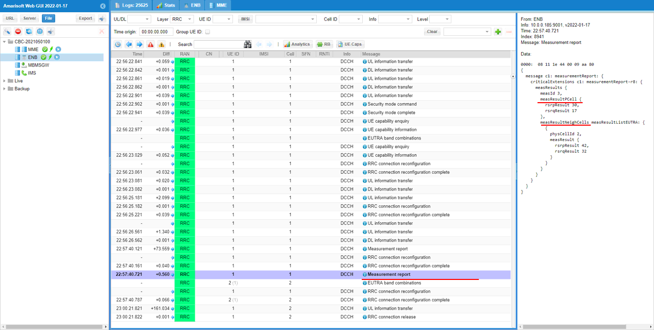
Once the cell power condition satisfies the configured measurement event, the UE sends a Measurement Report to the eNB. In this example, the Measurement Report includes measResults with measId: 3, and the serving cell result is shown under measResultPCell with rsrpResult and rsrqResult. More importantly, the report also includes measResultNeighCells, where the neighbour LTE cell is reported with physCellId: 2 and its measured RSRP/RSRQ values. This confirms that the UE successfully measured the inter-frequency neighbour cell and reported it to the network.
If you do not see measResultNeighCells in the Measurement Report, the eNB may not have enough information to trigger the handover. In that case, adjust the cell power again until the UE reports the neighbour cell properly. Based on this configuration, the eNB will trigger handover only after it receives the expected Measurement Report that satisfies the handover condition.
When the proper Measurement Report is received, the Callbox triggers handover by sending an RRC Connection Reconfiguration message that includes mobilityControlInfo. This IE is the actual handover command, because it tells the UE to move from the current serving cell to the target cell.
In this example, mobilityControlInfo includes targetPhysCellId: 2, which means the target cell is PCI 2. It also includes carrierFreq with dl-CarrierFreq 1575, which matches the target inter-frequency cell configured earlier. This confirms that the handover command is pointing to the intended target cell. The same message also carries the target cell access and lower-layer configuration, such as carrier frequency, RACH configuration, radioResourceConfigCommon, and radioResourceConfigDedicated, so that the UE can access and continue operation on the target cell after handover.
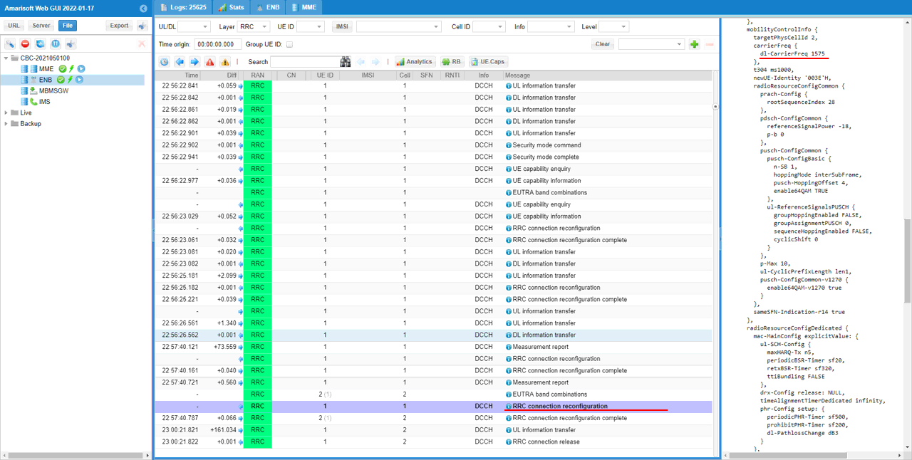
RRC / NAS Signaling
RrcConnectionReconfiguration
: This is the RrcConnectionReconfiguration message sent by eNB to configure Handover (
{
message c1: rrcConnectionReconfiguration: {
rrc-TransactionIdentifier 0,
criticalExtensions c1: rrcConnectionReconfiguration-r8: {
...
mobilityControlInfo {
targetPhysCellId 2,
carrierFreq {
dl-CarrierFreq 1575
},
t304 ms1000,
newUE-Identity '003E'H,
radioResourceConfigCommon {
prach-Config {
rootSequenceIndex 28
},
pdsch-ConfigCommon {
referenceSignalPower -18,
p-b 0
},
pusch-ConfigCommon {
pusch-ConfigBasic {
n-SB 1,
hoppingMode interSubFrame,
pusch-HoppingOffset 4,
enable64QAM TRUE
},
ul-ReferenceSignalsPUSCH {
groupHoppingEnabled FALSE,
groupAssignmentPUSCH 0,
sequenceHoppingEnabled FALSE,
cyclicShift 0
}
},
p-Max 10,
ul-CyclicPrefixLength len1,
pusch-ConfigCommon-v1270 {
enable64QAM-v1270 true
}
},
sameSFN-Indication-r14 true
},
radioResourceConfigDedicated {
mac-MainConfig explicitValue: {
...
},
physicalConfigDedicated {
...
}
},
securityConfigHO {
handoverType intraLTE: {
keyChangeIndicator FALSE,
nextHopChainingCount 0
}
},