SDR Check Up
The purpose of this tutorial is to shows how to check basic status and information about sdr cards installed on the callbox PC. This will help you to find root cause or troubleshoot for the sdr card related problems that you may face.
SDR stands for Software Defined Radio. The SDR card is the hardware card placed in PCI slots of the Callbox or UEsim. Each of the cards has multiple RF port (SMA type) where you connect antenna or coex cables. There are not so many cases where you need to check on SDR. But there are a few cases where it is worth checking SDR status/functionality.
Whenever you think you have any issues with sdr card (e.g, UE does not seem to receive any signal from Callbox), first suggestion is always to tweak the power of RF ports using tx_gain, rx_gain, t spl
If you end up with failure with the teaking the power tuning, it is not easy to confirm whether you have any issues with sdr power issue or timing/sync issue. so more practical advise would be ' do some sdr check up as in this tutorial whenever you have some problem and have done all other software related troubleshooting)
Table of Contents
- SDR Check Up
- Introduction
- Summary of the Tutorial
- Test Setup
- Key Command Line
- Check Up #1 : Errors / Warnings
- Check Up #2 : Check SDR Status with sdr_util
- Check SDR Status
- ./sdr_util -c all version
- ./sdr_util -c all sync_state
- ./sdr_util -c all gps_state
- ./sdr_util -c all clock_tune
- ./sdr_util -c all temp
- Sync with GPS
- Check Up #3 : Check SDR power with sdr_spectrum
- Check Up #4 : Running LTE on different sdr cards
- Check Up #5 : Clock Calibration
- Check Up #6 : Checkup for underflow/overflow
- Check Up #7 : Hardware Check-Up
- Additional Information
Introduction
Software Defined Radio (SDR) technology represents a transformative approach to radio communication systems by enabling the majority of radio functions, such as modulation, demodulation, and signal processing, to be implemented in software rather than hardware. SDR cards, which are specialized hardware modules typically installed in PCIe slots within systems like Callbox or UEsim, serve as highly flexible radio front-ends. Each SDR card is designed with multiple RF ports (commonly SMA type connectors), allowing for diverse connectivity options including antennas and coaxial cables. These cards interface directly with system software, facilitating real-time RF signal transmission and reception, and supporting a broad range of cellular and wireless standards. Within the Callbox ecosystem, SDR cards are pivotal for emulating network environments, running protocol stacks, and conducting comprehensive testing of wireless devices. Their configurability enables dynamic adjustment of RF parameters such as gain, frequency, and bandwidth, making them essential for troubleshooting and root cause analysis in laboratory and field scenarios. Understanding and monitoring the status of SDR cards is crucial for maintaining optimal system performance, diagnosing hardware or synchronization issues, and ensuring accurate test outcomes. This tutorial provides a systematic approach to checking the basic status and health of SDR cards installed on a Callbox PC, empowering engineers and technicians to efficiently identify and resolve SDR-related problems as part of broader troubleshooting workflows.
-
Context and Background
- SDR cards are integral hardware components in platforms such as Callbox and UEsim, providing the physical layer interface for wireless signal processing.
- The technology decouples radio functions from fixed hardware, allowing updates and adjustments via software, which supports rapid prototyping, testing, and deployment of new wireless standards.
- In a typical Callbox setup, each SDR card manages multiple RF ports, facilitating simultaneous multi-channel operation and extensive connectivity options.
-
Relevance and Importance of This Tutorial
- SDR card status directly impacts the fidelity and reliability of wireless testing environments, making regular health checks vital for consistent operation.
- Troubleshooting SDR cards helps in isolating hardware issues from software misconfigurations, streamlining the resolution process in complex test setups.
- This tutorial enables users to proactively identify potential SDR hardware faults or misconfigurations before they escalate into critical system failures.
-
Learning Outcomes
- Gain the ability to check and interpret basic SDR card status and health indicators on the Callbox PC.
- Understand the typical symptoms and scenarios where SDR card checks are necessary, such as unexpected signal loss or suspected hardware malfunction.
- Acquire practical troubleshooting skills for distinguishing between software and hardware-related RF issues.
- Learn to utilize key command-line utilities and logs relevant to SDR monitoring and diagnostics.
-
Prerequisite Knowledge and Skills
- Familiarity with the Callbox or UEsim test environments and their hardware architecture.
- Basic understanding of RF concepts, including signal gain, synchronization, and antenna connectivity.
- Experience with command-line interfaces in a Linux or Windows environment.
- General troubleshooting methodology for wireless communication systems.
Summary of the Tutorial
This tutorial provides a comprehensive set of check-up and troubleshooting procedures for SDR (Software Defined Radio) card functionality in a test setup environment. The following summarizes each test procedure, step-by-step methodologies, and essential checks described in the document:
-
Test Setup
- Connect antennas or RF cables to as many SDR cards as required for your testing scenario.
Key command-line utilities used:
- sdr_util
- sdr_test
- sdr_spectrum
Common sdr_util commands include:
- ./sdr_util -c all version
- ./sdr_util -c all sync_state
- ./sdr_util -c all gps_state
- ./sdr_util clock_tune
- ./sdr_util -c all temp
-
Check Up #1: Errors / Warnings
- Investigate explicit errors or warnings related to SDR cards (such as initialization failures, clock source issues, GPS synchronization errors, temperature alarms, or system errors).
- Do not proceed until the root cause of the error or warning is resolved.
-
Check Up #2: Check SDR Status with sdr_util
- Use sdr_util to check the status of installed SDR cards.
- Ensure LTE service is stopped before executing these commands (use service lte stop).
- Commands and their purposes:
- ./sdr_util -c all version: Lists basic information about all detected SDR cards; if any card is missing, perform a hardware checkup.
- ./sdr_util -c all sync_state: Verifies synchronization status, sync source, and clock source of each card. By default, SDR 0 is sync master and others are slaves.
- ./sdr_util -c all gps_state: Checks GPS status. If the GPS antenna is connected, look for 'GPS locked(active)'; otherwise, 'GPS not locked' indicates no GPS signal.
- ./sdr_util -c all clock_tune: Shows current clock drift. A value of 0 may indicate factory tuning has not been performed.
- ./sdr_util -c all temp: Reports temperature of each SDR card; if high temperature is reported, reboot and recheck before concluding an issue.
- Synchronizing with GPS: If a GPS antenna is connected, synchronize the SDR card with the GPS clock to improve performance (e.g., reduce BLER).
-
Check Up #3: Check SDR Power with sdr_spectrum
- Transmit a known reference signal from SDR and measure RF output power.
- Use a spectrum analyzer or another SDR card as a spectrum analyzer if dedicated equipment is unavailable.
- Refer to a separate tutorial for detailed steps on generating OFDM signals and measuring with sdr_spectrum.
-
Check Up #4: Running LTE on Different SDR Cards
- Troubleshoot attachment issues by running LTE (or NR) using only one SDR card at a time.
- Modify a copy of the configuration file (enb.default.cfg) for each SDR card under test.
- Restart LTE service, check SDR info using rf_info, and attempt to attach UE. Successful attachment and traffic indicate the SDR card is functioning.
- Repeat the procedure for each SDR card in the system.
- For multi-SDR configurations (e.g., running one NR cell on two SDRs for higher bandwidth), refer to the referenced tutorial.
-
Check Up #5: Clock Calibration
- If all previous checkups (particularly #1, #2, and #6) pass but issues persist, consider calibrating the SDR card clock to a GPS clock.
- Refer to the specified wiki for clock calibration procedures.
- Situations warranting calibration include long-term use (oscillator drift), synchronizing with other equipment, or excessive Carrier Frequency Offset (CFO) in UEsim scenarios.
-
Check Up #6: Checkup for Underflow/Overflow
- If underflow or overflow errors persist after prior checkups, consult the provided wiki for further troubleshooting steps.
-
Check Up #7: Hardware Check-Up
- If SDRs fail to work despite passing basic checkups, investigate hardware issues.
- Steps include:
- Remove all SDR cards; insert one card into a PCI slot and test individually using Checkup #2, Checkup #6, and by running LTE service with a single cell configuration. Repeat for each card.
- Identify working SDR cards.
- Install multiple confirmed-working cards, connect sync cables securely, and test multi-card operation (Checkup #2, #6, and LTE service with multi-cell configuration).
- If problems persist in multi-card setup, suspect sync cable or connection issues rather than the SDR cards themselves.
-
Additional Information: Max Power
- Maximum transmit power depends on frequency, bandwidth, and TX gain.
- Consult the appropriate documentation for SDR50 or SDR100 regarding measurement conditions and maximum power specifications.
This summary captures the stepwise diagnostic and validation process for SDR card operation, focusing on command-line checks, hardware verification, and systematic troubleshooting. Individual configuration parameters and commands are highlighted where essential for following the test procedures.
Test Setup
Test setup for this tutorial is as shown below. I would suggest you to connect antenna (or RF cables) to as many sdr cards as possible as per your needs.

Key Command Line
Followings are the list of the important command used in this tutorial.
- sdr_util
- ./sdr_util -c all version
- ./sdr_util -c all sync_state
- ./sdr_util -c all gps_state
- ./sdr_util clock_tune
- ./sdr_util -c all temp
- sdr_test
- sdr_spectrum
Check Up #1 : Errors / Warnings
When you have explicit errors or warnings about sdr cards. Some example of this kind of errors are as follows : ( NOTE : The full set of error/warning list is much longer than this, but I just tried to put some of the errors that most commonly happen. If you want to get the full list of error/warning, check out this file)
Some examples of commonly observed SDR-related errors are shown below. This is not the full list of all possible SDR errors or warnings, but it covers several cases that are often seen during Callbox or UEsim operation. For the complete list of SDR error and warning messages, refer to this file.
In general, these messages are useful because they can tell you whether the problem is related to SDR card detection, RF port access, clock synchronization, sample transmission, sample reception, or a lower-level driver issue. If you see one of these errors, do not immediately assume that the problem is in the UE, the test configuration, or the protocol stack. It is better to first confirm that the SDR card is properly detected, initialized, and synchronized before moving on to higher-layer troubleshooting.
In most cases, when you see this kind of SDR-related error or warning, the system cannot proceed normally. So the first step is not to debug the UE behavior or higher-layer protocol, but to find the root cause of the SDR error or warning and remove it first.
The important point is that these errors are usually not normal runtime messages. If any of these messages appear, first confirm the SDR card detection, clock configuration, sync source, cable connection, GPS/PPS availability, temperature condition, and driver status. After these SDR-level issues are cleared, then you can continue with RF power tuning, UE attach debugging, protocol log analysis, or other higher-layer troubleshooting.
- "*** Can't initialize phy ***"
- "Clock of device 'DDD' is not master - please check cables"
- "Clock of device 'DDD' is not slave - please check cables"
- Clock source of SDR device DDD should be set as master for the first one and slave for the others
- "Error: Timeout while waiting for the PPS"
- Timeout waiting for a valid SYNC signal (PPS).
- "Error: GPS time not available for sync"
- Sync is set as GPS but no signal received.
- "Can't init thread"
- Fatal system error
- "ERROR: OverTemp on 'DDD': FPGA:FFF� RFIC:RRR�"
- Temperature is above threshold for device DDD
- Low level internal error: retry
Check Up #2 : Check SDR Status with sdr_util
If you do not see any specific SDR-related warning or error, but you still suspect that the SDR card may not be functioning properly, the next practical step is to check the SDR status directly using sdr_util. This tool allows you to confirm whether the SDR card is detected by the system, whether the device information can be read correctly, and whether the basic hardware status looks normal.
This kind of check is useful when the problem is not obvious from the Amarisoft log. For example, the eNB or gNB may start without a clear fatal error, but the UE still does not receive the signal properly, the RF output looks abnormal, or the behavior changes depending on the SDR port or cable connection. In this case, sdr_util can help you separate SDR-level problems from RF power tuning, UE configuration, or protocol-level issues.
Check SDR Status
You may check on some basic status of sdr card using sdr_util.
Go to the directory /root/trx_sdr as shown below

Check how many SDR cards are installed and basic information of each cards. run ./sdr_util -c all version
This command checks all detected SDR cards and prints the version and basic device information. If the SDR card is detected correctly, you should see information for each SDR device in the output. If no SDR device is shown in the output, it usually means that the system cannot detect the SDR hardware properly. In that case, you need to perform a hardware-level check, such as confirming that the SDR card is installed correctly, the PCI connection is recognized by the system, the required cables are connected properly, and the SDR driver or firmware is in the expected state.
./sdr_util -c all version
This command returns the basic information of all SDR cards detected by the system. In the example below, the command detects three SDR devices: /dev/sdr0, /dev/sdr1, and /dev/sdr2.
./sdr_util -c all version
For each detected SDR card, the output shows the board ID, board master setting, board revision, FPGA revision, FPGA status, software version, and DNA value. The Board ID indicates the SDR hardware type. In this example, all three devices show 0x4b01 (SDR50), which means the detected SDR cards are SDR50 type devices. The FPGA revision shows the FPGA image version loaded on the SDR card, and the Software version shows the SDR software package version used by the system.
The FPGA status field is especially important. In this example, all three SDR cards show operational, which means that the FPGA is loaded and running normally. If the SDR card is detected but the FPGA status is not operational, it usually indicates a lower-level SDR initialization, firmware, or hardware problem that should be fixed before continuing with Callbox or UEsim operation.
The DNA value is a unique identifier of each SDR card. Even when multiple SDR cards are the same hardware type and use the same FPGA/software version, each card has a different DNA value. This can be useful when you need to distinguish one physical SDR card from another.
In this example, the important result is that three SDR cards are detected and all of them show normal version information with FPGA status operational. This means the basic SDR detection and FPGA loading status look normal. If your output does not show the expected number of SDR cards, or if one of the devices is missing from the list, you should check the SDR hardware installation, PCI connection, power, driver status, and any required hardware synchronization connection before continuing with higher-level troubleshooting.

./sdr_util -c all sync_state
: check if each of the sdr cards are synched and prints sync_src, clock_source etc
SDR50: In the case of SDR50, one SDR card is configured as the synchronization master and the other SDR cards are configured as synchronization slaves. Usually, the SDR card with sync_source = 0 works as the sync master, and it provides the synchronization signal to the other SDR cards whose sync_source is not 0. The sync ports of the SDR cards should be connected by sync cables, so the master SDR can distribute the timing reference to the slave SDR cards.
By default, /dev/sdr0 is configured as the sync source, which means it works as the sync master using an internal reference. The other SDR cards are configured as sync sink, which means they work as sync slaves using an external reference from the master SDR. If you are not using /dev/sdr0 and you are using other SDR cards only, one of the SDR cards actually used in the test should be configured as the sync source using the internal reference. Even in this case, /dev/sdr0 usually remains configured as internal by default.
Refer to the SDR50 user manual for the detailed hardware form factor and sync port structure.
In this example, /dev/sdr0 shows sync_source = 0 (internal), pps_locked = 1, clock_source = 0 (internal), and clock_pll_locked = 1. This means /dev/sdr0 is using its internal synchronization source and its clock PLL is locked correctly. The value pps_locked = 1 indicates that the PPS-related synchronization state is locked, and clock_pll_locked = 1 indicates that the clock PLL is also locked.
The other SDR cards, /dev/sdr1, /dev/sdr2, and /dev/sdr3, show sync_source = 2 (external), pps_locked = 1, clock_source = 1 (external), and clock_pll_locked = 1. This means these SDR cards are configured to use an external synchronization source and external clock source, which should come from the master SDR card through the sync cable connection. Since both pps_locked and clock_pll_locked are 1 for all slave SDR cards, the synchronization status looks normal in this example.
The important point in this output is that one SDR card is working as the internal sync master and the other SDR cards are working as external sync slaves. If any slave SDR shows pps_locked = 0 or clock_pll_locked = 0, it usually means that the synchronization signal is not being received or locked correctly. In that case, you should check the sync cable connection, master/slave configuration, SDR card selection, and whether the expected SDR card is actually being used by the Callbox or UEsim configuration.
NOTE : Refer to sdr50 user manual for the details of hardware form factor and structure

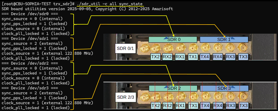
SDR100: In the case of SDR100, each SDR hardware module can run independently with its own internal clock and synchronization source. However, inside one SDR100 hardware module, there are two logical SDR devices. Among these two SDR devices, the first one works as the internal master and the second one works as the slave. So even though each SDR100 board can be independent from other SDR100 boards, the two SDR devices inside the same SDR100 board still have a master/slave relationship.
In the example below, /dev/sdr0 and /dev/sdr1 belong to one SDR100 hardware module, and /dev/sdr2 and /dev/sdr3 belong to another SDR100 hardware module. For the first SDR100 module, /dev/sdr0 shows sync_source = 0 (internal) and clock_source = 0 (internal), so it works as the internal synchronization master. /dev/sdr1 shows sync_source = 2 (external) and clock_source = 1 (external), so it works as the slave that receives the timing reference from /dev/sdr0 inside the same SDR100 module.
The same structure is shown for the second SDR100 module. /dev/sdr2 shows sync_source = 0 (internal) and clock_source = 0 (internal), so it works as the internal master for the second SDR100 module. /dev/sdr3 shows sync_source = 2 (external) and clock_source = 1 (external), so it works as the slave synchronized to /dev/sdr2.
The important fields to check are sync_pps_locked and clock_pll_locked. In this example, all SDR devices show sync_pps_locked = 1 (locked) and clock_pll_locked = 1 (locked), which means the PPS synchronization and clock PLL lock status are normal. If either of these values is 0 or not locked, it usually means that the SDR timing reference is not locked correctly, and you should check the SDR configuration, internal SDR pairing, cable connection if external sync is used, and whether the expected SDR devices are assigned correctly in the Callbox or UEsim configuration.
So the main difference from SDR50 is that SDR50 normally uses one card as the sync master and the other cards as sync slaves through sync cabling, while SDR100 has a paired SDR structure inside each hardware module. In SDR100, the first logical SDR in each module is normally the internal master and the second logical SDR is normally the slave. Therefore, when you check sync_state for SDR100, you should interpret the result by grouping the logical SDR devices by hardware module, such as /dev/sdr0 with /dev/sdr1, and /dev/sdr2 with /dev/sdr3.
./sdr_util -c all gps_state
This command checks the GPS lock status of all SDR cards detected by the system. It is useful when your SDR configuration is expected to use GPS-based synchronization, or when you want to confirm whether the GPS input of the SDR card is actually receiving a valid GPS signal.
In this example, all SDR devices show GPS not locked. This means that the SDR cards do not currently have a valid GPS lock. One common reason is that the GPS antenna is not connected to the GPS port of the SDR card, or the GPS antenna does not have a clear enough signal reception condition. This result is not always an error by itself. If your test setup does not use GPS synchronization, then GPS not locked may be expected and may not affect normal Callbox or UEsim operation.
The important point is to interpret this result together with your actual sync configuration. If GPS sync is not used, GPS not locked can simply mean that no GPS antenna is connected. If GPS sync is used, GPS not locked means the SDR timing source is not ready, and this should be fixed before continuing with RF or protocol-level troubleshooting.

If your SDR card is connected to a GPS antenna, you can check whether the GPS signal is properly detected by using the gps_state command. This check is mainly useful when your test setup is expected to use GPS-based synchronization, or when you want to confirm that the GPS antenna and SDR GPS input are working correctly.
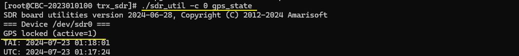
If /dev/sdr0 is connected to the GPS antenna, you can check the GPS status only for /dev/sdr0 by running the following command.If the GPS signal is properly detected, the output shows GPS locked (active=1), as shown in the example below. This means that the SDR card has successfully locked to the GPS signal and the GPS timing information is available. The output also shows TAI and UTC time values, which confirms that the SDR is receiving valid GPS time information.
In this example, the important part is GPS locked (active=1). If this value is shown, the GPS input is working normally from the SDR point of view. If the output shows GPS not locked instead, then you should check the GPS antenna connection, antenna placement, sky visibility, GPS port connection, and whether enough time has been given for the GPS receiver to acquire lock.
If the GPS signal is not detected, the output shows GPS not locked, as shown in the example below.
In this example, the command checks the GPS status of /dev/sdr1, and the result is GPS not locked. This means that /dev/sdr1 does not currently have a valid GPS lock. The most common reason is that the GPS antenna is not connected to this SDR card, or the antenna is connected but the GPS signal is not strong enough to acquire lock.
This result should be interpreted based on your actual configuration. If /dev/sdr1 is not supposed to use GPS synchronization, GPS not locked may be normal and does not necessarily indicate a problem. However, if /dev/sdr1 is configured to use GPS as its synchronization source, this is a problem and should be fixed before starting the Callbox or UEsim service. In that case, check the GPS antenna connection, GPS port selection, antenna location, sky visibility, and whether enough time has passed for GPS lock acquisition.

./sdr_util -c all clock_tune
This command shows the current clock tuning value applied to each SDR card. The value is shown as TCXO PWM tune in ppm, and it represents the frequency drift compensation value applied to the SDR clock. This value is normally adjusted during the factory tuning process so that the SDR clock can stay close to the expected reference frequency. (
In this example, the command shows the clock tuning value for each detected SDR device. /dev/sdr0 has TCXO PWM tune = -0.7 ppm, /dev/sdr1 has -1.2 ppm, /dev/sdr2 has -1.0 ppm, and /dev/sdr3 has -1.7 ppm. Since these values are not 0, it indicates that clock tuning values have been applied to these SDR cards.
So the important point is to interpret this result together with the actual sync role of the SDR card. If the SDR is used as the internal master or standalone timing source, the clock tune value should normally be properly configured. If the SDR is only a slave using an external clock source, the factory clock tune value may be less critical because the actual timing is coming from the external reference.

./sdr_util -c all temp
This command checks the temperature of all SDR cards detected by the system. It is useful when you suspect an SDR hardware problem, especially when you see an over-temperature warning or when the SDR stops working after running for some time.(
In this example, the command prints the temperature and voltage information for /dev/sdr0, /dev/sdr1, /dev/sdr2, and /dev/sdr3. Each SDR card shows the Board ID, RFIC temperature, FPGA temperature, and FPGA voltage values. The RFIC temperature is the temperature of the RF transceiver part, and the FPGA temperature is the temperature of the FPGA device on the SDR card. These are the main values to check when you are looking for a possible overheating problem.
In the example output, the RFIC temperatures are around 27 to 28 �C, and the FPGA temperatures are around 44 to 48.5 �C. These values look normal and do not indicate an overheating condition. If the temperature is much higher than normal, or if you see an over-temperature alarm in the log, you should check the PC cooling condition, airflow, fan operation, dust buildup, room temperature, and whether the SDR cards have been running under heavy load for a long time.
The voltage values, such as FPGA vccint, vccaux, and vccbram, are also shown for each SDR card. These values are mainly useful for checking whether the SDR power rails look normal. In most troubleshooting cases, you do not need to analyze these voltage values in detail unless you suspect a hardware or power supply issue.
One thing to note is that, in some very old software releases, a false high-temperature alarm may happen. So if you see a high-temperature alarm but the hardware condition does not look abnormal, it is worth rebooting the PC and checking the temperature again before concluding that the SDR card really has a temperature problem. If the high temperature is still reported after reboot, then you should treat it as a real hardware or cooling issue and fix it before continuing normal Callbox or UEsim operation.

Sync with GPS
If a GPS antenna is connected to the GPS input port of the SDR card, you can synchronize the SDR card with the GPS clock. This can improve the timing stability of the SDR and may help reduce RF-related issues such as BLER degradation, especially when the test setup requires an accurate external timing reference.
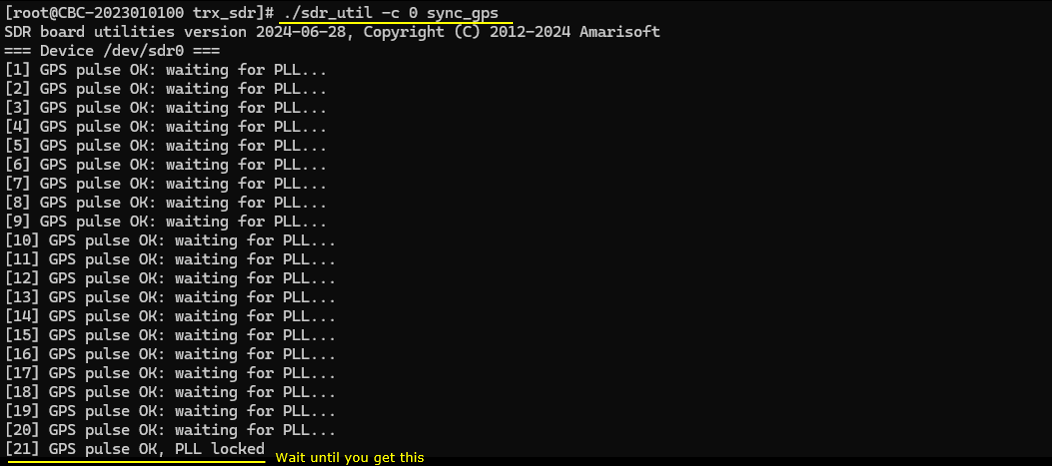
To synchronize /dev/sdr0 with GPS, run the following command.After running the command, the SDR first checks whether the GPS pulse is received correctly. In the example output, the message GPS pulse OK: waiting for PLL... is repeated several times. This means that the GPS pulse itself is detected, but the SDR clock PLL has not locked yet. You need to wait until the PLL lock process is completed.
When the synchronization is successful, the output shows GPS pulse OK, PLL locked. This is the expected final result. It means that the SDR card has received the GPS pulse and the internal PLL has locked to the GPS-based timing reference.
If the command keeps showing waiting for PLL for a long time, or if the GPS pulse is not detected, you should check the GPS antenna connection, GPS lock status, antenna placement, sky visibility, and whether the correct SDR device number is used in the command. Also make sure that GPS synchronization is actually required for your test setup before changing the sync configuration.
Check Up #3 : Check SDR power with sdr_spectrum
If you do not find any obvious issue from the previous SDR checks, the next step is to verify that the SDR is actually transmitting and receiving RF power correctly. One practical way to do this is to generate a known reference signal from the SDR and measure the signal power at the RF port.
This check is useful because many SDR-related problems are not caused by SDR detection, synchronization, or software configuration issues. Instead, they may be caused by RF path problems such as damaged cables, loose SMA connections, incorrect port selection, excessive attenuation, faulty RF components, or SDR hardware failures. By transmitting a known signal and measuring the resulting RF power, you can quickly determine whether the SDR RF chain is operating as expected.
You can generate a predefined reference signal using the SDR and then observe the signal with a spectrum analyzer. If a spectrum analyzer is available, it provides the most direct way to verify the transmitted frequency, signal shape, and output power level. If a dedicated spectrum analyzer is not available, another SDR card installed in the same system can be used as a simple spectrum analyzer by running the sdr_spectrum utility.
The goal of this test is not to perform detailed RF performance measurements, but to confirm that the SDR can generate a predictable RF signal and that the expected power is present at the RF port. If the measured power is significantly lower than expected, completely absent, or appears on an unexpected frequency, the problem is likely related to the SDR RF path rather than higher-layer software or protocol operation. This makes sdr_spectrum one of the most useful tools for isolating SDR hardware and RF issues after the basic status and synchronization checks have already passed.
Check out this tutorial for the details : sdr_test-generated OFDM signal on sdr 0 and sdr_spectrum on sdr 1
Check Up #4 : Running LTE on different sdr cards
This check is mainly useful when your system has multiple SDR cards and the UE still does not attach to the cell even after all previous SDR check-up procedures have been completed. For example, you may have already checked the SDR error messages, sdr_util status, sync_state, GPS status, temperature, and RF power, but the UE still cannot detect or attach to the LTE or NR cell.
The basic idea is to run a simple LTE or NR cell using only one SDR card at a time, and then repeat the same test with different SDR cards one by one. By doing this, you can check whether the problem happens with all SDR cards or only with a specific SDR card. If the same configuration works with one SDR card but fails with another SDR card, the issue is likely related to the failing SDR card, its RF port, its clock/sync setting, or the cable path connected to that card.
This test is especially helpful because a multi-SDR setup can make troubleshooting more complicated. When several SDR cards are used together, a failure may come from the SDR card itself, the synchronization between cards, RF port mapping, cable connection, or configuration mismatch. Running a simple single-SDR LTE or NR setup removes many of these variables and allows you to isolate the problem more clearly.
So the purpose of this check is not to verify full system performance, but to confirm whether each SDR card can independently support a basic cell operation. Once you identify which SDR card works and which one does not, you can focus the next troubleshooting step on the suspected SDR card, RF port, cable, or hardware connection instead of spending time debugging higher-layer protocol behavior.
Running on sdr 0
In this test, I first run a simple LTE cell on /dev/sdr0 and then repeat the same test on /dev/sdr1. If the UE can detect the cell and attach successfully in both cases, it means both SDR cards are basically functioning correctly from the LTE operation point of view.
For this test, I used enb.default.cfg as the baseline configuration and modified only the SDR-related part so that the LTE cell runs on the target SDR card. The purpose is to keep all other LTE parameters as similar as possible and change only the SDR card selection. This makes the comparison easier because, if the UE attach works on one SDR card but fails on another SDR card, the difference is likely coming from the SDR card, RF port, cable connection, or SDR hardware path rather than from the LTE configuration itself.
In this first step, the LTE cell is configured to run on /dev/sdr0. After starting the eNB, check whether the cell is transmitted normally and whether the UE can find the cell, camp on it, and complete attach. If this works normally, /dev/sdr0 can be considered functional for this basic LTE test.

I have added the following configuration changes for this test.
In the original enb.default.cfg, the RF driver configuration is usually included from a separate file by using the include line. For this test, I commented out the include line and added the RF driver configuration directly in the main configuration file so that I can explicitly select which SDR card is used.
The rf_driver section configures the eNB to use the SDR driver, and args: "dev0=/dev/sdr0" selects /dev/sdr0 as the SDR card for this test. The rx_antenna: "rx" setting specifies the receive antenna port name to be used by the SDR driver. This makes the test run only through the selected SDR card instead of relying on the default RF driver configuration.
I also added tx_gain and rx_gain directly in the configuration. tx_gain: 90 sets the transmit gain used for the downlink signal from the SDR, and rx_gain: 60 sets the receive gain used for uplink reception. These values are not necessarily the best values for every setup, but they provide a known starting point for this SDR card check. If the UE cannot detect the cell or attach, you may still need to adjust tx_gain, rx_gain, attenuation, or cable connection depending on your RF setup.
The important point in this configuration is that /dev/sdr0 is explicitly selected as the RF device. After applying this configuration, start the LTE service and check whether the UE can detect the LTE cell and attach successfully. If it works, then /dev/sdr0 is confirmed to be usable for this basic LTE operation test.

Restart the LTE service by running service lte restart, then reconnect to the Amarisoft screen session with screen -r and check rf_info in the eNB window. This command shows the RF driver status and the SDR device information currently used by the running LTE cell.
In this example, rf_info shows that the LTE cell is running with sample_rate = 5.760 MHz, dl_freq = 2680.000 MHz, ul_freq = 2560.000 MHz, band 7, dl_ant = 1, and ul_ant = 1. The TX0 line shows that the downlink is transmitted through port 0 with gain 89.8 dB at 2680 MHz, and the RX0 line shows that uplink reception is configured on port 0 with gain 60.0 dB at 2560 MHz. This confirms that the configured tx_gain and rx_gain are actually applied to the running SDR configuration.
The most important part of this output is PCIe RFIC /dev/sdr0. This confirms that the LTE cell is using /dev/sdr0, which is the SDR card selected in the configuration by args: "dev0=/dev/sdr0". The output also shows the SDR hardware information such as Hardware ID 0x4b01, FPGA revision, FPGA voltage values, FPGA temperature, RFIC temperature, and clock tune value. In this example, the FPGA temperature is 44.3 �C, the RFIC temperature is 28 �C, and the clock tune value is -0.7 ppm, so the basic SDR hardware status looks normal.
The TX underflows = 0 and RX overflows = 0 fields are also important. TX underflow means the SDR did not receive transmit samples fast enough from the software side, and RX overflow means the software side could not consume received samples fast enough from the SDR side. In this example, both values are 0, which means there is no obvious sample streaming problem at the time of this check.
So this rf_info output confirms that the eNB is running on /dev/sdr0, the expected RF frequency and gain values are applied, the SDR hardware information can be read normally, the temperature looks normal, and there are no TX underflow or RX overflow errors. After confirming this, you can continue the actual UE attach test and check whether the UE can detect and attach to the LTE cell using this SDR card.

Now run the trace command in the eNB console and let the UE attach to the cell, as shown below.
If the UE successfully attaches and you see traffic in the trace output, it is a good indication that the SDR card is functioning properly for this basic LTE operation. In this example, the trace shows PRACH detection first, followed by UE traffic statistics after the UE is connected. The PRACH line indicates that the eNB received the UE random access preamble, and the following rows show downlink and uplink activity for the attached UE.
The DL side shows values such as CQI, MCS, retransmission count, transmitted OK count, bitrate, and SNR. The UL side shows values such as PUCCH SNR, uplink MCS, received OK count, retransmission-related counters, bitrate, timing advance, and power-related information. Since both downlink and uplink traffic are visible, this confirms that the SDR is not only transmitting the cell signal, but also receiving uplink signal from the UE.
This does not guarantee that the SDR card has no issue under every possible condition. There can still be SDR problems that appear only with a specific bandwidth, frequency band, RF port, MIMO configuration, or higher traffic load. However, if the UE can attach successfully and some traffic is exchanged, you can at least say that there is no critical SDR problem for this basic single-cell LTE test on this SDR card.

Running on sdr 1
In this test, I repeat the same LTE cell test using /dev/sdr1 instead of /dev/sdr0. The purpose is to check whether the second SDR card can also run a basic LTE cell and support UE attach normally. If the UE can attach successfully when the cell is running on /dev/sdr0 and also when the same cell is running on /dev/sdr1, you can say that both SDR cards are functioning correctly for this basic LTE operation.
For this test, I used enb.default.cfg as the baseline configuration again and changed only the SDR-related configuration so that the LTE cell uses /dev/sdr1. Keeping the rest of the configuration the same is important because it makes the test result easier to compare. If the UE attaches on /dev/sdr0 but fails on /dev/sdr1, the difference is more likely related to the SDR card, RF port, cable path, or SDR synchronization setting rather than the LTE cell configuration itself.
This test is not intended to prove full SDR performance for every bandwidth, band, MIMO mode, or RF condition. It is a simple isolation test to confirm whether /dev/sdr1 can transmit the LTE cell signal and receive the UE uplink signal well enough for attach and basic traffic.
I have added the following configuration changes for running the LTE cell on /dev/sdr1.
As in the previous test, the original RF driver include line is commented out, and the rf_driver section is added directly in the main configuration file. The main difference from the /dev/sdr0 test is the args field. In this case, args: "dev0=/dev/sdr1" explicitly selects /dev/sdr1 as the SDR card used by the LTE cell. The name: "sdr" field tells Amarisoft to use the SDR RF driver, and rx_antenna: "rx" specifies the receive antenna path.
The tx_gain: 90 and rx_gain: 60 values are kept the same as in the /dev/sdr0 test. This is important because the purpose of this procedure is to compare SDR cards under the same RF configuration as much as possible. If you change the gain values, attenuation, cable path, or other LTE parameters at the same time, it becomes harder to determine whether the difference comes from the SDR card itself or from the changed RF condition.
After applying this configuration, restart the LTE service and check rf_info again from the eNB console. In the rf_info output, confirm that the active SDR device is shown as PCIe RFIC /dev/sdr1. If the eNB is still showing /dev/sdr0, it means the configuration change was not applied correctly or the service was not restarted with the modified configuration.
Once /dev/sdr1 is confirmed in rf_info, run the trace command and let the UE attach to the cell. If the UE can attach and you can see downlink and uplink traffic, then /dev/sdr1 is also working normally for this basic LTE test.

Restart the LTE service by running service lte restart, then reconnect to the Amarisoft screen session with screen -r and check rf_info in the eNB window. This confirms whether the modified configuration is really using /dev/sdr1.
In this example, rf_info shows the same LTE cell configuration as before: sample_rate = 5.760 MHz, dl_freq = 2680.000 MHz, ul_freq = 2560.000 MHz, band 7, dl_ant = 1, and ul_ant = 1. The TX0 line shows gain 89.8 dB at 2680 MHz, and the RX0 line shows gain 60.0 dB at 2560 MHz. This confirms that the same RF gain and frequency settings are being used for the /dev/sdr1 test.
The most important part of this output is PCIe RFIC /dev/sdr1. This confirms that the eNB is now running on /dev/sdr1, not /dev/sdr0. The SDR information also shows Hardware ID 0x4b01, FPGA revision 2021-10-08, FPGA temperature 48.6 �C, RFIC temperature 29 �C, and clock tune -1.2 ppm. These values look normal for this basic check.
The TX underflows = 0 and RX overflows = 0 fields are also important. Since both values are 0, there is no obvious transmit or receive sample streaming issue at the time of this check. The DMA buffer usage is also shown as 0/2048 for both TX and RX, which does not indicate any immediate buffer problem.
So this output confirms that the LTE cell is now running on /dev/sdr1, the expected RF frequency and gain values are applied, the SDR hardware information can be read normally, the temperature looks normal, and there are no TX underflow or RX overflow errors. After confirming this, run the trace command and check whether the UE can attach and exchange traffic through this SDR card.

Now run the trace command in the eNB console and let the UE attach to the cell.
In this example, the trace output first shows PRACH detection, which means the eNB received the UE random access preamble. After that, the table shows UE traffic statistics, which means the UE has attached and started exchanging traffic with the cell.
The DL part shows downlink-related information such as CQI, rank indicator, MCS, retransmission count, transmitted OK count, bitrate, and SNR. The UL part shows uplink-related information such as PUCCH SNR, uplink MCS, received OK count, bitrate, timing advance, and power-related values. Since both DL and UL activity are visible, this confirms that /dev/sdr1 is transmitting the downlink signal and receiving the uplink signal from the UE.
If the UE successfully attaches and you see some traffic, it is a good indication that the SDR card is functioning properly for this basic LTE test. This does not guarantee that the SDR card is completely problem-free in every condition. There may still be issues that appear only with a specific bandwidth, frequency, RF port, MIMO configuration, or high traffic load. However, at least for this simple LTE attach and traffic test, you can say that there is no critical problem with /dev/sdr1.
Running one cell(one NR Cell) on 2 x sdr 20
In some cases, each SDR card may work fine when it is tested independently, but you may still see problems when multiple SDR cards are combined to run one cell. This can happen, for example, when you try to run a wider-bandwidth NR cell that requires more RF bandwidth than a single SDR card can support. In that case, one logical NR cell may be transmitted and received through multiple SDR cards working together. For this operation, refer to this tutorial.
This kind of test is different from the previous single-SDR test. In the previous test, each SDR card was checked one by one, and the goal was to confirm whether each card could independently support a basic LTE or NR cell. In this test, the goal is to check whether multiple SDR cards can work together correctly as one combined RF system. Even if each SDR card passes the single-card test, the combined setup may still fail if there is a synchronization issue, wrong SDR mapping, wrong RF port connection, or incorrect configuration for the multi-SDR operation.
When you run one NR cell on 2 x SDR 20, you should pay special attention to the clock and sync relationship between the SDR cards. The SDR cards must be synchronized properly so that the transmitted and received sample streams are aligned in time and frequency. If the cards are not synchronized correctly, the UE may fail to detect the cell, may detect the cell but fail during random access, or may attach but show poor RF performance such as high BLER, unstable throughput, or frequent retransmissions.
So this check is mainly for cases where the basic SDR status looks normal and each SDR works individually, but the problem appears only when two SDR cards are used together for one wider-bandwidth NR cell. In that situation, the troubleshooting focus should move from individual SDR health to multi-SDR synchronization, RF port mapping, cable connection, and whether the combined SDR configuration matches the intended NR cell bandwidth and antenna configuration.
Check Up #5 : Clock Calibration
If all the previous check-up steps do not show any obvious problem, but the SDR still does not work properly, you may need to consider clock calibration. In this context, clock calibration means tuning the SDR card clock against a GPS reference clock so that the SDR internal oscillator can be corrected more accurately.
Regarding how to do clock calibration, refer to this wiki.
Amarisoft SDR cards are normally delivered with factory clock calibration already applied, so clock calibration is not usually the first thing to suspect. In most cases, SDR problems are more likely to come from configuration, RF cabling, sync source selection, GPS/PPS connection, RF gain, or hardware detection issues. However, there are some situations where clock calibration can be worth trying.
One example is when the SDR card has been used for a long time, such as several months or years, and the internal oscillator may have drifted from its original calibrated value. Another case is when you want to synchronize your eNB, gNB, or Callbox with another external test equipment and you need more accurate frequency alignment. Clock calibration may also be useful when you are using an SDR card on UEsim and you notice that the CFO is too high. As a practical criterion, if abs(CFO) is larger than the SCS in Hz, it is strongly recommended to try clock calibration. This assumes that there is no clock problem on the eNB or gNB side. If the network-side clock itself is not accurate, then the CFO observed on UEsim may not be caused by the UEsim SDR card.
So clock calibration should be treated as a later-stage troubleshooting step. You normally try it after confirming that SDR detection, sync_state, GPS status, temperature, RF power, and basic single-SDR operation look normal, but the system still shows symptoms that may be related to frequency accuracy or clock drift.
In summary, you may consider trying this calibration in some situation exampled below.
- It has been used over long time (months/years) and the internal oscillator might have drifted
- You want to synchronize our enb/gnb with a other test equipment
- If you are using SDR card on UEsim and notice the CFO is too high (NOTE : if abs(CFO) > SCS (in Hz), it is strongly suggested to try clock calibration. this criteria is based on assumption that there is no clock issue on gNB/eNB side)
Check Up #6 : Checkup for underflow/overflow
When you have 'underflow / overflow' even after all the previous checkup has passed, I would suggest you to check out this wiki.
Check Up #7 : Hardware Check-Up
There are some cases where most of the basic SDR check-up steps pass, but the SDR still does not work properly for the complete call connection. For example, Check Up 1, 2, 6 may not show any obvious error, the SDR may be detected correctly, and the basic status may look normal, but the UE still fails to attach or the RF behavior is still abnormal.
In this case, you may need to consider a hardware-level check. Unfortunately, there is no single simple or deterministic method to find the root cause of every hardware issue. The practical approach is to inspect the physical setup step by step, such as checking whether the SDR card is properly inserted into the PCIe slot, whether the SDR card is detected consistently after reboot, whether the RF cables and SMA connectors are firmly connected, whether the sync cables are connected correctly, whether the GPS/PPS or external clock cable is connected to the expected port, and whether the RF port mapping matches the configuration.
It is also useful to open the PC chassis, if you are allowed to do so, and try different physical combinations. For example, you may reseat the SDR card, move the SDR card to another PCIe slot, swap RF cables, swap sync cables, or compare the behavior with another SDR card that is known to work. If the problem follows a specific SDR card, the card itself may be suspicious. If the problem follows a specific PCIe slot, cable, RF port, or sync path, then the issue may be in that physical connection rather than in the SDR card itself.
Since hardware issues are often case-dependent, the purpose of this section is to collect practical trials and observations from real troubleshooting cases. The goal is not to define one fixed procedure, but to provide a set of things to check when the normal software-level and SDR utility-level checks do not reveal the root cause.
Check if each individual sdr card works
Pick one PCI slot and insert only one SDR card into that slot. Then check whether the card works normally. The purpose of this test is to isolate the SDR card itself from other possible variables. If multiple SDR cards are installed at the same time, it may be difficult to know whether the problem is caused by a specific SDR card, a PCI slot, a sync cable, RF cabling, or multi-SDR configuration. By testing only one SDR card at a time in the same PCI slot, you can make the test condition much simpler and easier to compare.
After inserting one SDR card, boot the PC and first perform Checkup #2 to confirm that the SDR card is detected properly by sdr_util and that the basic device information is shown correctly. Then perform Checkup #6 to verify the RF power path with a known signal. After that, run the LTE or NR service using a simple single-cell configuration, such as enb.default.cfg or gnb-sa.cfg, and check whether the UE can detect the cell, complete random access, attach successfully, and exchange some traffic.
If the card works with no problem, power down the PC, remove that SDR card, insert another SDR card into the same PCI slot, and repeat the same procedure. Testing all SDR cards in the same PCI slot allows you to compare the cards under the same hardware condition. If one card fails while the other cards work in the same slot, that specific SDR card is suspicious. If all cards work normally in the same slot, then each SDR card is likely functioning properly by itself.
Once all individual SDR cards are confirmed to work, but the full system still fails when multiple SDR cards are installed together, the problem is more likely related to PCI slot combination, sync connection, clock configuration, RF port mapping, cable connection, or multi-SDR configuration rather than a completely faulty SDR card.
For SDR 50
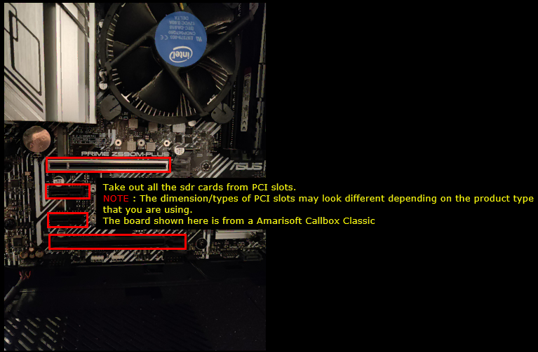
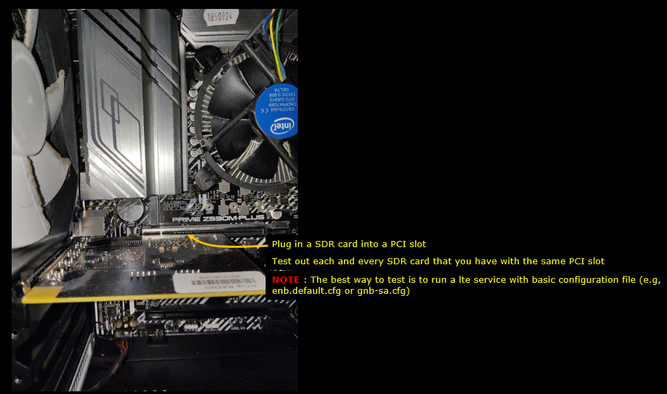
First, take out all SDR cards from the PCI slots. After removing the SDR cards, you will see the empty PCI slots as shown below. The exact number and type of PCI slots can vary depending on the Amarisoft product and PC hardware that you are using. In this example, the picture is from an Amarisoft Callbox Classic, so your system may look different if you are using a different Callbox model or UEsim PC.
The purpose of this step is to start from a clean hardware condition and then insert one SDR card at a time. By doing this, you can check whether each SDR card is detected and works properly in a specific PCI slot. If you install all SDR cards at once, it may be difficult to know which card or which slot is causing the problem. But if you test one card at a time, you can isolate the issue more clearly.
After removing all SDR cards, visually inspect the PCI slots and make sure there is no obvious physical damage, dust, loose connector, or object blocking the slot. Then insert only one SDR50 card into one PCI slot, boot the PC, and check whether the SDR card is detected by sdr_util. If the card is detected and works normally, repeat the same test with the next SDR card or the next PCI slot as needed. This kind of step-by-step test can help you determine whether the problem follows a specific SDR card, a specific PCI slot, or a specific combination of card and slot.
Pick any one PCI slot, insert only one SDR card, and check whether the card works normally. The purpose of this test is to remove as many variables as possible by using only one PCI slot and one SDR card at a time. If you test multiple SDR cards at the same time, it can be difficult to know whether the problem comes from the SDR card, the PCI slot, the sync connection, or the RF path.
For this check, first insert one SDR card into the selected PCI slot and boot the PC. Then perform Checkup #2 to confirm that the SDR card is detected correctly by sdr_util and that the basic SDR information can be read. After that, perform Checkup #6 to confirm that the SDR can transmit or receive a known RF signal and that the RF power path looks normal. Then run the LTE or NR service with a simple single-cell configuration, such as enb.default.cfg or gnb-sa.cfg, and check whether the UE can detect the cell, perform random access, attach successfully, and exchange some traffic.
If there is no problem with these steps, power down the PC, remove the SDR card, insert another SDR card into the same PCI slot, and repeat the same procedure. By testing all SDR cards with the same PCI slot, you can check whether each individual SDR card works under the same hardware condition. If all SDR cards work normally in the same slot, the SDR cards themselves are likely OK. If only one specific SDR card fails in the same slot while the others work, that SDR card becomes suspicious.
Once you confirm that all SDR cards work individually, you can say that each SDR card is basically functioning OK. After this, if the complete multi-SDR setup still fails, the problem is more likely related to the PCI slot combination, synchronization between SDR cards, RF cable connection, port mapping, or multi-SDR configuration rather than a completely dead SDR card.
In summary, the procedure goes as follows
Pick any one PCI slot and plug in only one of your sdr cards and check if it works. And then check if the card works with no problem. For this checking, I would try followings
- i) Perform Checkup #2
- ii) Perform Checkup #6
- iii) Run lte service with any single cell configuration (e.g, enb.default.cfg or gnb-sa.cfg) and check if the initial attach with UE complete successfully
- iv) If there is no problem with step i),ii),iii), pull out the sdr cards, plug in another sdr cards and repeat the step i), ii), iii)
- v) Identify all the sdr cards that is working OK.
Check if Multiple cards works
After confirming that each SDR card works individually, the next step is to check whether multiple SDR cards can work together in the same system. This is an important check because some problems appear only in multi-card operation, even when each SDR card works normally by itself.
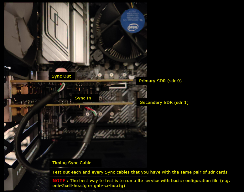
For SDR50, install two SDR cards into two PCI slots and connect the sync cable between them. One SDR card should work as the primary card, usually /dev/sdr0, and the other card should work as the secondary card, usually /dev/sdr1. Make sure the sync cable is connected from Sync Out of the primary SDR to Sync In of the secondary SDR, and confirm that the cable is firmly inserted into the socket. If the sync cable is loose, connected incorrectly, or defective, you may see problems such as sync lock failure, TX underflow, RX overflow, second cell detection failure, or UE attach failure.
For SDR100, check the clock cable connection between the SDR100 modules. Even though each SDR100 module can work independently with its own internal clock, multiple SDR100 modules should share a common clock when they are used together in multi-card scenarios such as Carrier Aggregation, handover, or multi-cell testing. One module should act as the clock master, and the other modules should receive the clock from the master. Make sure Clock Out and Clock In are connected in the correct direction and that all cables are firmly plugged in.
After the physical connection is checked, perform Checkup #2 and confirm that all expected SDR devices are detected by sdr_util. Then check the sync_state result and make sure the master/slave relationship is correct and that the lock status looks normal. After that, perform Checkup #6 to confirm that the RF power path works as expected.
Finally, run the LTE or NR service with a simple multi-card configuration, such as enb-2cell-ho.cfg or gnb-sa-ho.cfg, and check whether the UE can detect the cell, complete random access, attach successfully, and exchange traffic. If this works, it is a good indication that the SDR cards, PCI slots, sync or clock cables, RF ports, and multi-card configuration are working properly together.
If each SDR card works individually but the multi-card test fails, the problem is more likely related to the sync cable, clock cable, master/slave configuration, PCI slot combination, RF port mapping, or multi-SDR configuration rather than a completely faulty SDR card.
For SDR 50
If you have confirmed in the previous step that each SDR card works individually, the next step is to check whether those SDR cards also work correctly in a multi-SDR configuration. This is important because a card may work normally by itself, but still fail when it needs to operate together with another SDR card through timing synchronization.
For this test, plug two SDR50 cards into two PCI slots and connect the timing sync cable between them, as shown below. One card works as the primary SDR, usually /dev/sdr0, and the other card works as the secondary SDR, usually /dev/sdr1. The sync cable should be connected from the Sync Out port of the primary SDR to the Sync In port of the secondary SDR. This allows the secondary SDR to receive the timing reference from the primary SDR.
The exact sync cable connection method can vary depending on the SDR card type, such as SDR50 or SDR100, and also depending on the Amarisoft product type. The example shown here is for SDR50 cards installed in a Callbox Classic, so your hardware layout may look different.
After connecting the two SDR cards and the sync cable, boot the PC and check the SDR status again. First confirm that both SDR cards are detected with sdr_util, then check sync_state and make sure that the primary SDR is configured as the internal sync source and the secondary SDR is configured as the external sync sink. You should also confirm that pps_locked and clock_pll_locked are both locked for the SDR cards.
Then run the LTE or NR service with a basic multi-SDR configuration, such as enb-2cell-ho.cfg or gnb-sa-ho.cfg, and check whether the UE can detect the cell, attach, and exchange traffic. If the individual SDR test passed but this multi-SDR test fails, the problem is more likely related to sync cable connection, sync cable quality, master/slave configuration, PCI slot combination, RF port mapping, or multi-SDR configuration rather than a completely faulty SDR card.
It is also a good idea to test each timing sync cable with the same pair of SDR cards. If one sync cable works and another sync cable fails with the same SDR cards and same configuration, then the cable itself becomes suspicious.
In short, Plug in two sdr cards in two PCI slots and connect Sync cable as shown below (
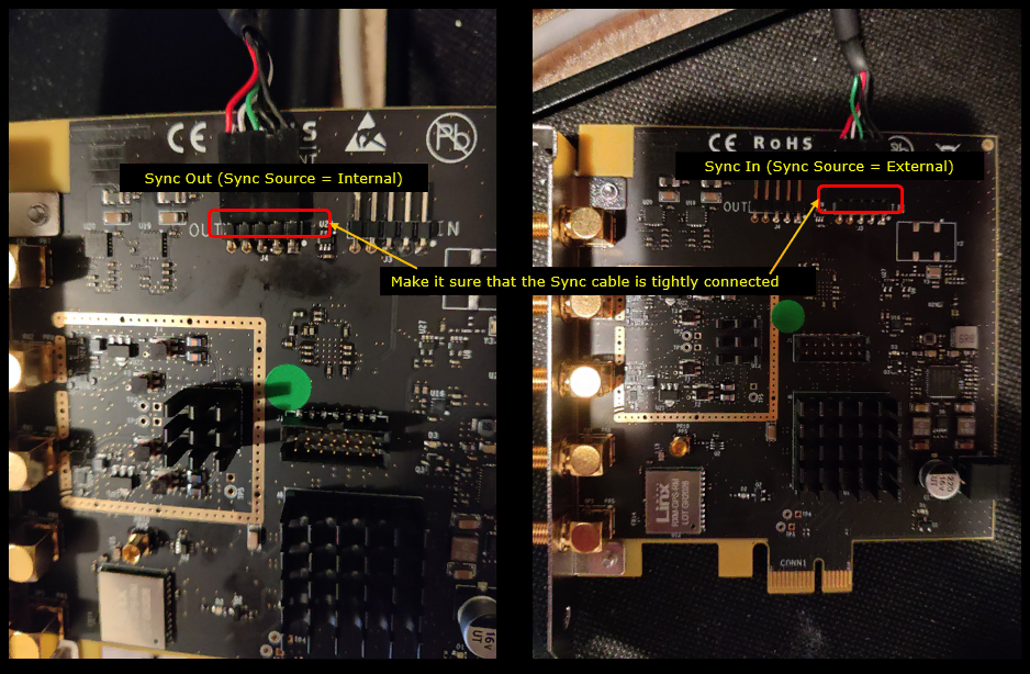
If the sync cable is loose, connected to the wrong port, or has a problem by itself, you may see many different symptoms. For example, the second SDR card may not be detected correctly, the service may show TX underflow or RX overflow, the second cell may not be detected by the UE, or the UE may fail during attach even though each SDR card works fine individually. In some cases, the problem may look like an RF issue or protocol issue, but the real cause can simply be unstable synchronization between the SDR cards.
So whenever you use multiple SDR50 cards together, always check the physical sync cable connection first. Make sure the connector is tightly seated, the cable is connected in the correct direction from Sync Out to Sync In, and the sync_state output shows the expected internal/external configuration with the lock status properly set.
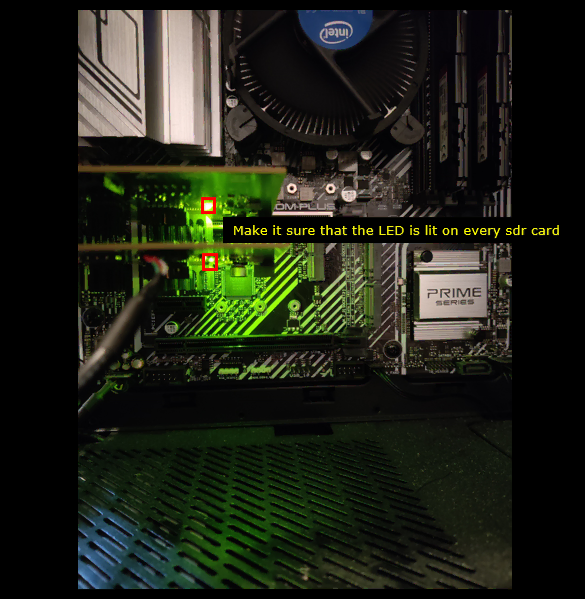
Make sure that the green LED is lit on each SDR card. This is a simple but useful hardware check because the LED gives a quick indication that the SDR card is powered and physically active.
After inserting the SDR cards into the PCI slots and connecting the sync cable, power on the PC and visually check the LEDs on the SDR cards. In the example shown below, the green LEDs are lit on both SDR cards. This is the expected condition. If the LED on one SDR card is not lit, that card may not be powered correctly, may not be seated properly in the PCI slot, or may have a hardware issue.
If you do not see the green LED, power off the PC first, then reseat the SDR card firmly into the PCI slot and check again. You may also try another PCI slot or compare with another SDR card that is known to work. If the same SDR card still does not show the LED in different slots, the SDR card itself becomes suspicious. If other SDR cards also fail to show the LED in the same PCI slot, the PCI slot or motherboard side may be suspicious.
Now check whether the SDR cards work correctly in a multi-card configuration. At this stage, each SDR card has already been checked individually, so the purpose of this test is to confirm whether the cards can also work together with the proper sync connection and multi-SDR configuration.
First, perform Checkup #2 again and confirm that all installed SDR cards are detected by sdr_util. Then perform Checkup #6 to verify that the RF power path looks normal. After that, run the LTE service with a basic two-cell configuration, such as enb-2cell-ho.cfg, and check whether the UE can detect the cell, complete random access, attach successfully, and exchange some traffic.
If the UE attaches successfully in this two-card configuration, it is a good indication that the SDR cards, PCI slots, sync cable, and multi-SDR setup are working properly together. If the individual SDR tests passed but this multi-card test fails, focus your troubleshooting on the sync cable connection, sync_state result, master/slave configuration, PCI slot combination, RF port mapping, and whether the two-cell configuration is correctly mapped to the intended SDR cards.
In summary, Check out if the sdr cards work with multi card configuration as follows :
- i) Perform Checkup #2
- ii) Perform Checkup #6
- iii) Run lte service with any two cell configuration (e.g, enb-2cell-ho.cfg) and check if the initial attach with UE complete successfully
For SDR 100
Even though each SDR100 hardware module can work independently with its own internal clock, one SDR100 module should work as the clock master and the other SDR100 modules should work as clock slaves when they are used together in a multi-card configuration, such as Carrier Aggregation, handover, or any test scenario where multiple SDR cards need to operate with a common timing reference.(
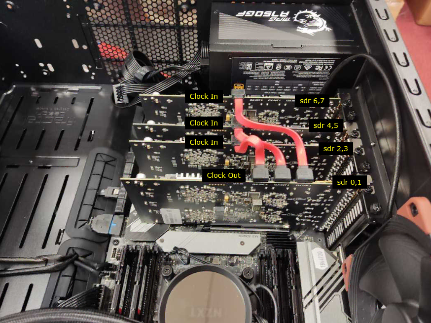
In this case, the first thing to check is whether the clock cables are connected properly, as shown below. The clock output of the master SDR100 module should be connected to the clock input of the slave SDR100 modules. In the example shown here, the lower SDR100 module, which corresponds to SDR 0/1, provides the clock output, and the upper SDR100 modules receive the clock input. This allows all SDR100 modules to run with the same clock reference.
Make sure that all clock cables are firmly plugged into the connectors. Even if the cable looks connected, it may still be slightly loose, and this can cause clock or synchronization errors during the test. A loose or bad clock cable can create many different symptoms, such as SDR initialization failure, clock lock failure, unstable RF behavior, UE attach failure, poor BLER, or problems that appear only when multi-card scenarios are used.
So when troubleshooting SDR100 multi-card operation, do not check only the software configuration. Also check the physical clock cable path carefully. Confirm which SDR100 module is the master, which modules are slaves, whether Clock Out is connected to Clock In in the expected direction, and whether the cables are firmly seated in all connectors. Once the cabling is confirmed, check the SDR status with sdr_util and verify that the clock and sync state are locked before running the actual LTE or NR test scenario.
Now check whether the SDR cards work correctly in a multi-card configuration. At this point, the physical clock cable connection has already been checked, so the next step is to confirm that the software and RF operation also work correctly with multiple SDR100 modules installed together.
First, perform Checkup #2 and confirm that all expected SDR devices are detected by sdr_util. For SDR100, remember that one physical SDR100 module appears as two logical SDR devices, so you should check whether the expected device pairs, such as /dev/sdr0 and /dev/sdr1, or /dev/sdr2 and /dev/sdr3, are shown correctly. Also check the sync_state output and make sure that the master/slave clock relationship is consistent with your cable connection.
Then perform Checkup #6 to verify that the RF power path works as expected. This helps confirm that the SDR cards are not only detected by the system, but also able to transmit or receive RF signal through the expected ports.
After that, run the LTE service with a basic two-cell configuration, such as enb-2cell-ho.cfg, and check whether the UE can detect the cell, complete random access, attach successfully, and exchange traffic. If this test works, it is a good indication that the SDR100 cards, clock cables, PCIe connection, RF ports, and multi-card configuration are working properly together.
If the individual SDR test passed but the multi-card test fails, focus your troubleshooting on the clock cable connection, clock master/slave configuration, sync_state result, PCI slot combination, RF port mapping, and whether the two-cell configuration is using the intended SDR devices.
In short, check out if the sdr cards work with multi card configuration as follows :
- i) Perform Checkup #2
- ii) Perform Checkup #6
- iii) Run lte service with any two cell configuration (e.g, enb-2cell-ho.cfg) and check if the initial attach with UE complete successfully
Additional Information
Max Power
the max power would vary depending on frequency, bandwidth and tx_gain. The measurement condition for the documentation is a little different between SDR 50 and SDR100. You need to refer to different document depending on the type of SDR card you are using.
- For SDR 100, refer to this document
- For SDR 50, refer to this document