NR 1 Band 2 sdr
The purpose of this tutorial is to show you how to use multiple sdr cards combined (called Stereo Mode) to implement wide bandwidth that is wider than the maximum bandwidth of single sdr card. As of now, Amarisoft products are based on one of the following two types sdr cards as follows. The main difference between them are maximum bandwidth it can cover.
- SDR50 : It can conver up to 50Mhz bandwidth. Callbox mini and Callbox Classics are using this type of sdr cards. (For further details of this type, check out this document)
- SDR100 : It can cover up to 100Mhz bandwidth. Callbox Pro, Callbox Ultimate are using this type of sdr cards. (For further details of this type, check out this document)
There is no issues (no major differences) for LTE regardless of whether you use SDR50 or SDR100 since the max bandwidth of LTE is only 20 Mhz, but there would be some cases where you come across issues for NR if you are using SDR50 since there are various kinds of configuration that uses the bandwidth wider than 50Mhz. Then how do we test NR with Bandwidth greater than 50Mhz with sdr50 ? This tutorial would provide you with the solution for the case. The idea is to combine two sdr50 cards that enables to handle max 100 Mhz bandwidth.
Table of Contents
Introduction
Software Defined Radios (SDRs) have revolutionized wireless communications by providing flexible, programmable platforms capable of emulating a variety of radio protocols and adapting to new standards through software updates. In the context of wireless network testing and development, products like Amarisoft Callbox utilize advanced SDR hardware to emulate base stations and user equipment for technologies such as LTE and 5G NR (New Radio). One of the architectural challenges faced in modern 5G NR testing environments is the requirement for extremely wide channel bandwidths, often exceeding the maximum supported by a single SDR card. To address this, Amarisoft's Callbox platforms implement a technique known as Stereo Mode, where multiple SDR cards are synchronized and combined to operate as a single logical interface, effectively aggregating their individual bandwidth capabilities. For example, while the SDR50 card supports up to 50 MHz of RF bandwidth and the SDR100 supports up to 100 MHz, certain NR test scenarios—especially those simulating high-capacity or carrier aggregation use cases—may require more than 50 MHz on platforms equipped only with SDR50 cards. Stereo Mode enables two SDR50 cards to be used together to deliver up to 100 MHz bandwidth, thus overcoming hardware limitations without the need for a more expensive SDR100 card. This capability is critical for comprehensive NR testing and ensures that test equipment can keep pace with evolving wireless standards. Understanding and correctly configuring Stereo Mode is essential for engineers and testers aiming to validate wideband NR configurations, optimize performance, and ensure conformance with 3GPP specifications within the Amarisoft testing ecosystem.
-
Context and Background
- SDRs serve as the backbone for flexible wireless protocol implementation in test, measurement, and research environments.
- Amarisoft Callbox platforms utilize SDR50 and SDR100 hardware, with bandwidth limitations dictated by the specific card in use.
- Modern 5G NR deployments often require channel bandwidths exceeding 50 MHz, making advanced SDR configurations necessary for accurate emulation.
- Stereo Mode is a proprietary feature that enables the aggregation of two SDR cards, effectively doubling the available bandwidth on compatible platforms.
-
Relevance and Importance of the Tutorial Topic
- Enables users to test and validate NR scenarios that exceed the capabilities of a single SDR50 card by leveraging hardware aggregation.
- Facilitates cost-effective testing solutions by allowing continued use of existing SDR50 hardware for wideband scenarios, delaying or obviating the need for immediate SDR100 upgrades.
- Addresses critical testing requirements for 5G NR, including wideband channels, non-contiguous carrier aggregation, and high-throughput scenarios.
- Ensures that test setups remain compliant with industry standards and support the full spectrum of NR use cases.
-
Learning Outcomes
- Understand the architectural principles behind SDR bandwidth aggregation and Stereo Mode.
- Gain practical knowledge of configuring and deploying multiple SDR cards in tandem for wideband NR testing.
- Learn best practices for synchronizing SDR hardware, managing resource allocation, and troubleshooting common issues in multi-card setups.
- Acquire the skills necessary to extend the lifespan and utility of SDR50-based platforms in advanced testing environments.
-
Prerequisite Knowledge and Skills
- Familiarity with SDR concepts and basic operation of Amarisoft Callbox products.
- Understanding of LTE and NR (5G) channel bandwidth requirements and typical network deployment scenarios.
- General competence in configuring test equipment, interpreting wireless standards, and basic networking concepts.
- Some experience with Linux environments and basic hardware setup is recommended for hands-on configuration tasks.
Summary of the Tutorial
This tutorial details the procedures and methodologies for configuring and testing NR Standalone (SA) and Non-Standalone (NSA) cells with 100 MHz bandwidth using multiple SDR50 cards, as a single SDR50 can only support up to 50 MHz bandwidth. The tutorial covers two main test scenarios and provides tips for SDR card combinations.
-
Test 1: NR SA 100 MHz BW with 2 x SDR50
- Purpose: Demonstrate configuration of a single NR SA cell with 100 MHz bandwidth using two SDR50 cards.
-
Configuration Steps:
- Use the configuration file gnb-sa-2sdr-0-1.cfg, modified from the standard configuration.
- Set NR_BANDWIDTH to 100 MHz.
- Specify both SDR devices in the args parameter:
args:"dev0=/dev/sdr0,dev1=/dev/sdr1" - Configure n_subband in rf_ports to enable bandwidth aggregation across two SDR cards.
- Adjust sample_rate and guard_band parameters for optimal operation of combined SDRs.
-
Test Execution:
- Start LTE service and check cell configuration on the (enb) screen to verify intended bandwidth settings.
- Review tx_gain and rx_gain values; note that default/max gain settings remain unchanged compared to the single SDR case.
- Check RF configuration for each SDR using rf_info to determine the tuned center frequencies.
- Enable BCCH log capturing for further analysis.
- Check ss-PBCH-BlockPower to observe how it varies with bandwidth and frequency.
- Power on the UE and allow it to complete the attach procedure.
-
Test 2: NR NSA 100 MHz BW with 2 x SDR50 (Total 3 SDR50s)
- Purpose: Demonstrate configuration of a dual cell (LTE and NR) NSA setup, where 100 MHz NR cell uses two SDR50 cards and LTE cell uses a third SDR50.
-
Configuration Steps:
- Use the configuration file gnb-nsa-2sdr-1-2.cfg, modified from gnb-nsa.cfg.
- Set NR_BANDWIDTH to 100 MHz; TRX_MAX_BANDWIDTH being less than NR_BANDWIDTH triggers automatic multi-SDR selection.
- Enable three SDR devices in the args parameter:
args:"dev0=/dev/sdr0,dev1=/dev/sdr1,dev2=/dev/sdr2" - Configure n_subband in rf_ports for the NR cell to utilize two SDR cards; the configuration for combining SDRs is auto-handled in the latest release.
- Adjust sample_rate and guard_band as needed; no manual changes required for auto-handled fields.
-
Test Execution:
- Start LTE service and verify cell configurations, ensuring bandwidth settings match the intended test case.
- Review tx_gain and rx_gain settings; note these remain consistent with single SDR scenarios.
- Check RF configuration for each SDR card to confirm proper setup.
- Power on the UE, allow it to complete the attach, and verify assignment of one core network ID and two distinct cell IDs (one for LTE, one for NR) to the same UE in NSA mode.
-
Tips: Using Other SDR Card Combinations
- To use different SDR card pairs (e.g., SDR1 and SDR2, or SDR2 and SDR3), adjust the args parameter accordingly, for example:
- args: "dev0=/dev/sdr1,dev1=/dev/sdr2" // uses SDR1 and SDR2
- args: "dev0=/dev/sdr2,dev1=/dev/sdr3" // uses SDR2 and SDR3
- To use different SDR card pairs (e.g., SDR1 and SDR2, or SDR2 and SDR3), adjust the args parameter accordingly, for example:
The tutorial emphasizes adjusting configuration files, properly assigning SDR devices, tuning RF parameters, and validating the test setup using system logs and UE behavior. Detailed message contents and protocol specifics are intentionally omitted in favor of focusing on high-level test methodologies and configuration procedures.
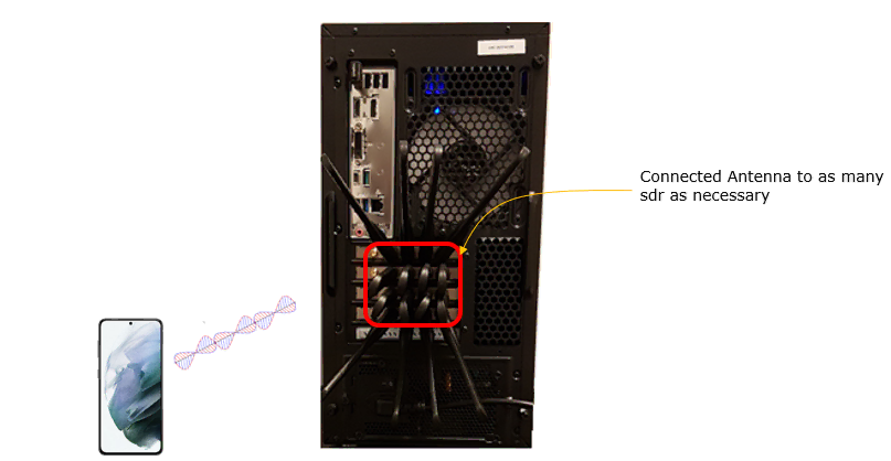
Test Setup
Test setup for this tutorial is as shown below.
- SIM Card used in this tutorial is the one delivered with the system as it is.
- If you want to change the configuration, The tutorial Configuration Guide would help
Key Configuration Parameters
Followings are important configuration parameters for this tutorial. You may click on the items for the descriptions from Amarisoft documents.
- rf_driver
- rf_ports
- sample_rate
- n_subband
- guard_band
- band
- bandwidth
Test 1 : NR SA 100 Mhz BW with 2 x sdr50
In this test, I will show you how to configure a SA cell of 100Mhz BW using two sdr50. The max bandwidth that can be supported by a sdr50 is 50Mhz. So with sdr50 card, it would have not been able to simulate a cell with bandwidth greater than 50Mhz. To overcome this limitation, we implemented the feature to combine two sdr50 cards to simulate a cell with the bandwidth greater than 50 Mhz. So in this test, we need to use two SDR 50 cards even though the number of cell is only one.
Configuration
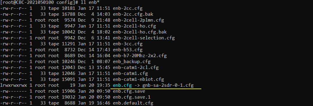
I used the configuration file gnb-sa-2sdr-0-1.cfg which is copied from gnb-sa.cfg and modified.
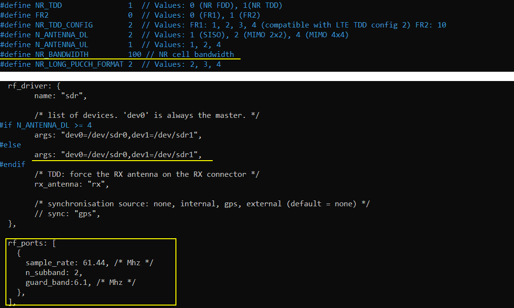
Configured in gnb-sa-2sdr-0-1.cfg is as shown below. I set NR_BANDWIDTH to 100 Mhz. args:"dev0=/dev/sdr0,dev1=/dev/sdr1" mean that two sdr card sdr0 and sdr1 will be enabled for this test. Another important parameter to configure one cell with multiple sdr card is n_subband parameter in rf_ports. The sample_rate and guard_band are configured to fine tune the two combined sdr cards.
Perform the Test
Run LTE service and check cell configuration in (enb) screen as shown below. Confirm that the Bandwidth are configured as you intended.

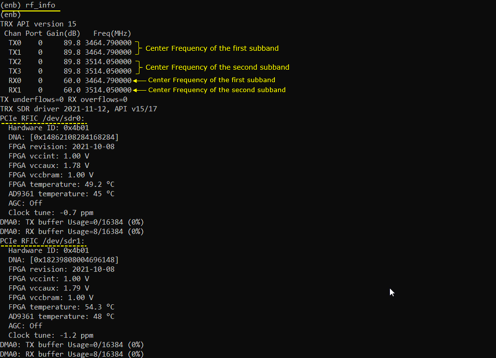
Check tx_gain and rx_gain and see if there is any changes comparing to 1 sdr cases. (NOTE : the default / max gain are same as 1 sdr case). In this case, TX0 and TX1 is from sdr0. TX2 and TX3 is from sdr1. RX0 is for sdr0 and RX1 is for sdr1.

Check how RF of each sdr cards are configured. With rf_info command, you can figure out the center frequencies that each sdr cards are tuned to.
Enable bcch log capturing in (enb) as shown below

Check ss-PBCH-BlockPower as shown below. This value would vary depending on channel Bandwidth and Frequency.

Power on UE and let it complete the attach

Test 2 : NR NSA 100 Mhz BW with 2 x sdr50
In this test, I will show you how to configure a NSA cell of 100Mhz BW using three sdr50. The max bandwidth that can be supported by a sdr50 is 50Mhz. So with sdr50 card, it would have not been able to simulate a cell with bandwidth greater than 50Mhz. To overcome this limitation, we implemented the feature to combine two sdr50 cards to simulate a cell with the bandwidth greater than 50 Mhz. So in this test, we need to use three SDR 50 cards in total even though the number of cell is only two. One LTE cell uses one sdr50 card and one NR cell uses tw0 sdr50 cards in this test.
Configuration
I used the configuration file gnb-nsa-2sdr-1-2.cfg which is copied from gnb-nsa.cfg and modified.
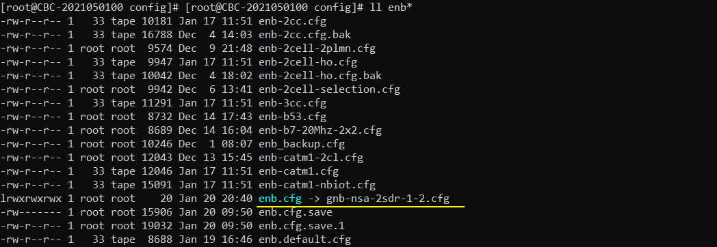
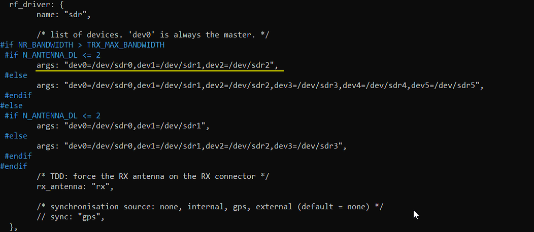
Configured in gnb-sa-2sdr-1-2.cfg is as shown below. I set NR_BANDWIDTH to 100 Mhz. If TRX_MAX_BANDWIDTH is narrower than NR_BANDWIDTH, multi sdr card is automatically selected.

args:"dev0=/dev/sdr0,dev1=/dev/sdr1,dev2=/dev/sdr2" mean that two sdr card sdr0,sdr1 and sdr2 will be enabled for this test. The configuration in gnb-nsa.cfg in 2021-11-19 release is automatically handling dev with combined sdr card as follows. This is just for your reference. You don't need to change anything in this part.
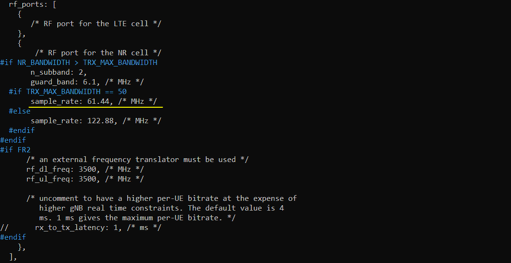
Another important parameter to configure one cell with multiple sdr card is n_subband parameter in rf_ports. The sample_rate and guard_band are configured to fine tune the two combined sdr cards. The configuration in gnb-nsa.cfg in 2021-11-19 release is automatically handling rf_ports with combined sdr card as follows. This is just for your reference. You don't need to change anything in this part.
Perform the Test
Run LTE service and check cell configuration in (enb) screen as shown below. Confirm that the Bandwidth are configured as you intended.

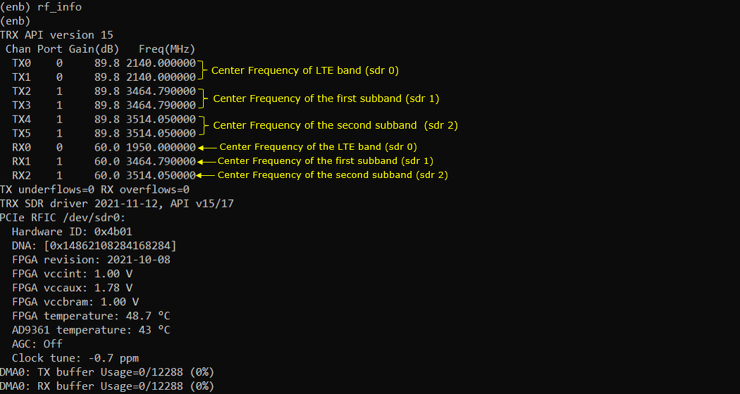
Check tx_gain and rx_gain and see if there is any changes comparing to 1 sdr cases. (NOTE : the default / max gain are same as 1 sdr case)

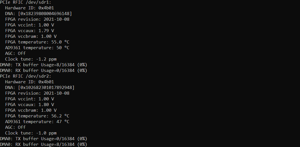
Check how RF of each sdr cards are configured.
Power on UE and let it complete the attach
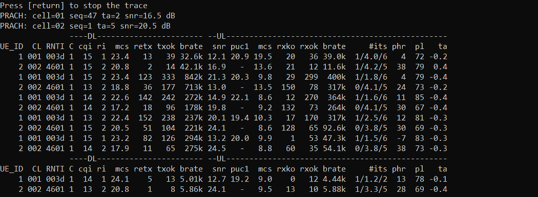
Check out ue configuration. You would notice that one core network id is assigned and two different cell ID (RAN ID) and RAN_UE_ID are assigned for the same UE in case of NSA cell. One of the cell ID is for LTE cell and the other is for NR cell.

Tips
Using other combinations of sdr card
If you want to combine other two sdr cards (i.e, other than sdr 0 and sdr 1), you can do it by simply changing sdr card number as shown below.
args: "dev0=/dev/sdr
args: "dev0=/dev/sdr