Out of the Box Test - NR NSA
The purpose of this tutorial is to show you how to establish NR NSA connectivitybetween a UE and Amari Callbox. It is assumed that you don't have any previous experience with Amari callbox.
SA stands for "Non-Stand Alone". "Non Stand Alone" in NR NSA implies a fewthings as below
- It support NR with help of other technology (e.g, LTE). In most common form of NSA called ENDC, NR is supported with the help of LTE. In this configuration, LTE plays a role as an anchor (MCG) which performs the initial attach and most of signaling and NR plays a role as secondary cell (SCG) which provides additional pipe for user traffic
- (In ENDC) NR Core is not supported and NR is directly/indirectly connected to LTE Core.
According to NR deployment options described in RP-161266, There are many different forms of NSA is defined in this document, but when we say 'NSA' as of now, it usually mean Option 3.x (i.e, Option 3 and/or Option 3a)(
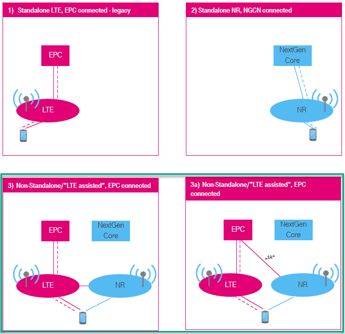
In terms of the frequency and bands, Amarisoft Callbox (gNB) support all the frequencies and bands that are specified in 3GPP. In terms of bandwidth, Amarisoft Callbox (gNB) support any 3gpp defined band upto 100Mhz per component carrieras of now.
Table of Contents
- Out of the Box Test - NR NSA
- Introduction
- Summary of the Tutorial
- Test Setup
- Key Configuration Parameters
- Test 1 : Basic NSA (Single LTE + Single NR)
- Configuration
- Check if LTE service is Running
- Perform the Test
- Log Analysis
- Generating Traffic
- Analysis in Screen during traffic test
- Traffic Analysis on WebGUI
- Test 2: 6LTE CA+ Single NR
- Configuration
- 1st LTE Cell
- 2nd LTE Cell
- 3rd LTE Cell
- 4th LTE Cell
- 5th LTE Cell
- 6th LTE Cell
- Common to AllLTE Cell
- NRCell
- Perform the Test
- Log Analysis
- Test 3: 5LTE CA(FDD + TDD)+ Single NR
- Configuration
- Global Parameters
- 1st LTE Cell
- 2nd LTE Cell
- 3rd LTE Cell
- 4th LTE Cell
- 5th LTE Cell
- NRCell
- Common to All LTE Cell
- Perform the Test
- Log Analysis
- RRC / NAS Signaling
- Tips
- Troubleshoot
Introduction
The evolution of mobile network technology has led to the development of 5G New Radio (NR), which is designed to deliver significantly higher data rates, ultra-low latency, and enhanced connectivity compared to previous generations. One of the pivotal deployment strategies for 5G NR is the Non-Stand Alone (NSA) architecture, where 5G NR is integrated with existing LTE infrastructure to facilitate a smoother transition from LTE to full 5G Stand Alone (SA) networks. In NSA mode, LTE serves as the Master Cell Group (MCG), managing initial network attachment and control signaling, while NR operates as the Secondary Cell Group (SCG), supplementing data throughput and network capacity. This dual-connectivity approach, commonly referred to as E-UTRA NR Dual Connectivity (ENDC), enables operators to leverage their existing LTE core networks (EPC) while introducing NR capabilities. The Amarisoft Amari Callbox provides a comprehensive test and development platform for both LTE and NR, allowing users to emulate network elements such as the gNB (NR base station) and eNB (LTE base station), and manage both LTE and NR core network functionalities through a unified 'mme' core. This is particularly significant for research, validation, and troubleshooting in NR NSA deployments, as the Callbox supports all 3GPP-defined frequency bands and bandwidths up to 100 MHz per component carrier. Understanding and establishing NR NSA connectivity between a User Equipment (UE) and the Amari Callbox is essential for network engineers, researchers, and developers aiming to validate device interoperability, optimize network performance, and accelerate 5G adoption in real-world scenarios.
-
Context and Background
- 5G NR NSA Architecture: Integrates NR with LTE, enabling early 5G deployments by utilizing existing LTE infrastructure as the primary control and signaling anchor.
- ENDC (E-UTRA NR Dual Connectivity): Allows simultaneous connection of a UE to both LTE (eNB) and NR (gNB) nodes, with LTE handling mobility and initial attachment, and NR boosting user data performance.
- Amarisoft Amari Callbox: A flexible network emulation platform supporting both LTE and NR, with a unified core network component ('mme') for comprehensive NSA testing.
- Industry Deployment Options: Focuses on Option 3.x (Option 3 and Option 3a), the most prevalent form of NSA as per 3GPP RP-161266, where NR is anchored by LTE and connected to the LTE core.
-
Relevance and Importance of the Tutorial
- Enables users to establish and validate NR NSA connectivity in a controlled environment, which is critical for device certification, interoperability testing, and performance benchmarking.
- Provides hands-on experience with Amarisoft Amari Callbox, a widely used platform for R&D, prototyping, and troubleshooting in 4G/5G mobile networks.
- Facilitates understanding of dual connectivity mechanisms, network architecture, and signaling flows in NR NSA deployments.
-
Learning Outcomes
- Gain practical knowledge of configuring and operating the Amari Callbox for NR NSA scenarios.
- Understand the roles of LTE and NR in NSA, including signaling, data transfer, and core network integration.
- Learn to troubleshoot common NSA setup failures using dedicated guides and Callbox diagnostic tools.
- Acquire insights into 3GPP deployment options and how they map to real-world test and deployment environments.
-
Prerequisite Knowledge or Skills
- Basic understanding of mobile network concepts (LTE, NR, core network architecture).
- Familiarity with RF fundamentals and 3GPP specifications is helpful but not mandatory.
- No prior experience with the Amari Callbox is required, as the tutorial is designed for beginners.
Summary of the Tutorial
This tutorial covers three main NSA (Non-Standalone) test scenarios using Amarisoft Callbox, focusing on configuration, execution, and verification methodologies. The procedures are outlined for basic NSA operation, advanced carrier aggregation with NSA, and mixed FDD/TDD carrier aggregation with NSA. Key troubleshooting and configuration management steps are also provided.
-
Test 1: Basic NSA (Single LTE + Single NR)
- Test Setup: Use the default NSA configuration file (gnb-nsa.cfg) without modification. The SIM card provided with the system is utilized.
- Configuration:
- Set up enb.cfg as a symbolic link to gnb-nsa.cfg in the eNB/gNB configuration directory.
- Ensure that ims.cfg and mme.cfg are correctly linked in the /root/mme/config directory.
- Execution:
- Restart the Callbox to apply configuration changes.
- Verify LTE service is running using service lte status.
- Access the system via screen -r to monitor and control network components.
- Switch to the ENB component (Ctrl+A+1), verify RF and cell configuration with cell phy and cell main commands.
- Start trace logging with the t command.
- Power on UE and observe the attach and NSA establishment process. Stop trace with the Enter key.
- Check UE connectivity and IP assignment using ue command in ENB and MME.
- Log Analysis:
- Analyze /tmp/gnb0.log for NSA setup, focusing on measurement report configuration, RRC messages, and RACH procedure for NR cell addition.
- Traffic Generation and Analysis:
- Generate IP traffic (e.g., browser-based speed test) after NSA establishment.
- Monitor throughput and troubleshoot using t, t spl, and t cpu commands in the screen session.
- Optionally, use WebGUI for detailed throughput and retransmission analysis.
-
Test 2: 6 LTE Carrier Aggregation (CA) + Single NR
- Test Setup: Requires hardware resources for 7 cells (ideally 7 SDR cards, or multiple cells per SDR if supported).
- Configuration:
- Use gnb-6LTE-1NR-nsa.cfg, based on gnb-nsa.cfg.
- Configure six LTE cells (each mapped to a separate rf_port with unique dl_earfcn values) as Primary or Secondary Component Carriers (SCC).
- Configure one NR cell as TDD, band n78, mapped to rf_port 6.
- Ensure NR measurement configuration (Event B1) is present in all LTE cells to trigger NR addition based on UE measurement report.
- Execution:
- Verify all cell configurations using cell phy and cell commands.
- Start trace logging with t command, attach UE, and monitor for NR cell addition.
- Log Analysis:
- Review UE capability enquiry and information messages to ensure support for desired LTE CA and NSA configurations.
- Confirm that measurement objects and report configurations are present for all LTE and NR cells.
- Verify sequence: measurement report from UE, RRCConnectionReconfiguration messages, NR cell addition as SCG, and successful NR RACH procedure.
-
Test 3: 5 LTE CA (FDD + TDD Mix) + Single NR
- Test Setup: Requires hardware for 6 cells (6 SDR cards or multi-cell per SDR where feasible).
- Configuration:
- Use gnb-cc-mix_TDD_FDD-nsa.cfg, based on gnb-nsa.cfg.
- Configure five LTE cells with a mix of FDD and TDD duplex modes, each mapped to a unique rf_port and dl_earfcn.
- Apply TDD-specific parameters (uldl_config, sp_config, tdd_ack_nack_feedback_mode) for TDD cells.
- Configure NR cell as TDD, band n78.
- Set common parameters for all LTE cells, including periodic CSI reporting, TM3, and Measurement Report (B1) for NSA initiation.
- Execution:
- Verify all cell configurations with cell phy and cell commands.
- Attach UE, start trace logging, and wait for NR cell addition.
- Log Analysis:
- Check UE capability enquiry and information for LTE CA and NSA band support.
- Confirm configuration of measurement objects and report configurations for all involved bands.
- Verify the sequence of measurement reports, RRCConnectionReconfiguration, NR cell addition, and completion of NR RACH procedure.
- Ensure traffic flows and CSI reports are received for both LTE and NR as configured.
- RRC/NAS Signaling:
- Examine the structure of key RRC messages, especially rrcConnectionReconfiguration for NR addition.
Configuration File Management: Copy existing configuration files as templates for new tests, modify as required, and set symbolic links accordingly. Avoid modifying default files directly.
Troubleshooting Guidelines:
- Ensure UE supports the required NSA band combinations and DCNR.
- Verify correct measurement and report configuration in RRC messages.
- Check physical connections, gain settings, and UE logs if measurement reports are missing.
- Analyze SCG Failure messages for root cause analysis if NSA setup fails after RRC procedures.
This summary encapsulates the end-to-end procedures for NSA testing from configuration to troubleshooting, with emphasis on command-line interaction, RAN-side verification, capability checks, and log analysis.
Test Setup
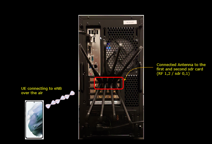
Test setup for this tutorial is as shown below.
- Since this test is for Out of the box testing, I used the default nsaconfiguration(gnb-nsa.cfg) file without changing anything in it
- SIM Card used in this tutorial is the one delivered with the system as it is.
- If you want to change the configuration, The tutorial Configuration Guidewould help
Key Configuration Parameters
Followings are important configuration parameters for this tutorial. You may click on the items for the descriptions from Amarisoft documents.
- cell_list
- cell_default
- nr_cell_list
- nr_cell_default
- meas_config_desc : In this link you will get the descriptions for all the items listed below
- a1_report_type
- a1_rsrp
- a1_hysteresis
- a1_time_to_trigger
- a2_report_type
- a2_rsrp
- a2_hysteresis
- a2_time_to_trigger
- a3_report_type
- a3_offset
- a3_hysteresis
- a3_time_to_trigger
- rsrp_filter_coeff
- nr_b1_report_type
- nr_b1_rsrp
- nr_b1_hysteresis
- nr_b1_time_to_trigger
- nr_rsrp_filter_coeff
- meas_gap_config
Test 1 : Basic NSA (Single LTE + Single NR)
This is the simplest and the most basic test for NSA which involves only one LTE Cell and only one NR Cell. The main purpose is to introduce basic operation with default sample configuration.
Configuration
By default, Amari Callbox uses enb.cfg for eNB/gNB configuration. This default configuration is configured for LTE band 3, band 4. If you want to use the call box for other RAT (Radio Access Technology) like 5G or other LTE bands (i.e, bands other than band 3, 7), you need to change the configuration.
In this section, I would show you how to change the configuration file that is used by eNB/gNB. But in this very basic tutorial (Out of the Box Test), I would not try to change the detailed configuration within the file and will just replace the enb.cfg with another file.
Go to eNB/gNB configuration directory

change the symbolic link so that enb.cfg points to { enb.cfg -> gnb-nsa.cfg }using following command


Now go to the directory /root/mme/config. You should see the configuration files as below.

If ims.cfg and mme.cfg is not linked to the files as shown above, you may run following commands to make proper link.
![]()
Restart the callbox so that the new configuration file is applied

Check if LTE service is Running
Whatever you want to test, the first thing you need to do is that call box program (LTE Service) is running. You can check on the execution status of the call box program by running following command and you should get the result as shown below
# service lte status
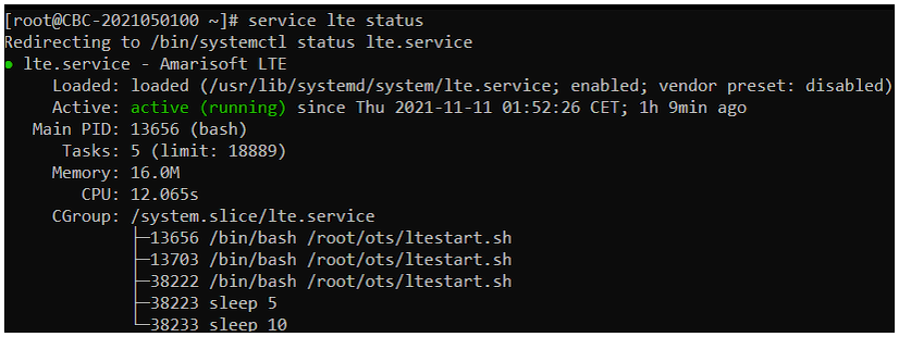
NOTE : Getting this result is pre-requisite for Call Box Operation, but this result itself does not guarantee the normal operation. If you see some unexpected issues. You may restart the call box with following command
# service lte restart
Perform the Test
If it is confirmed that the lte service is running, go to screen mode by running 'screen -r' and follow through the steps as shown below. The steps shown here is the procedure that you would use for almost every test and it is highly recommended to get familiar with these steps. For further commands you can use in this screen mode, refer to the tutorial : Command Line Command
First open the screen window with the 'screen' command. (

You will get the screen as shown below. This screen shows all the network components installed in the callbox. In this tutorial, it indicates MME, ENB, IMS, MBMSGW are installed in the callbox.
You would see a number before each component name. With Ctrl+A and the number before the component name, you can switch to command line window for the specific component. For example, if you press Ctrl+A+1, the command line window switches to ENB and if you press Ctrl+A+0, the command line window switches to MME and so on.
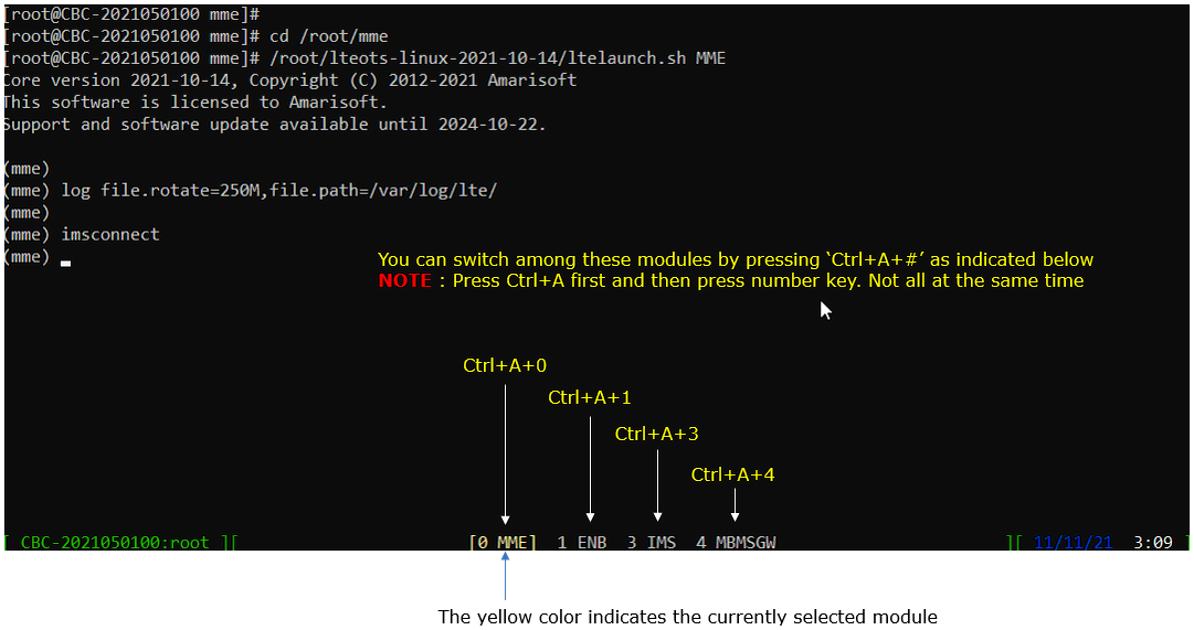
Switch to [ENB] by pressing { Ctrl + A + 1 }. You will get the screen as shown below
When you switches to [ENB] there are some important information provided without running any specific command. It provides RF information showing the sample_rate, dl_freq, ul_freq, band, dl_ant, ul_ant that gives you very fundamental RF information. Check out the details of these info and see if the RF is configured as you intended.
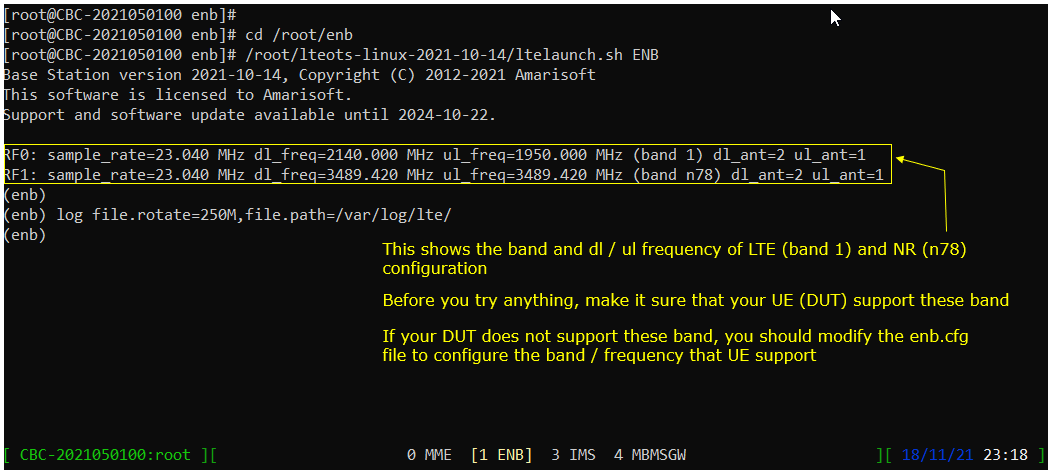
You can confirm the cell configuration (e.g, RAT type, BW, frequency etc) using cell commands.
If you run 'cell phy' command, you will get the basic physical configuration for the cells that are configured in the test. RAT, BAND, BW, ARFCN, SCS are the most common items to be checked before you move on with the test.

If you run 'cell main' or just 'cell' command, you will get some additional information that is not shown with 'cell phy', for example, PCI, TAC, plmn and dl_gain.

Start trace logging by 't' command as shown below.
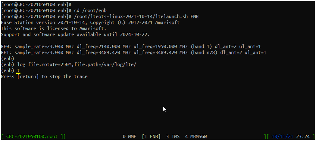
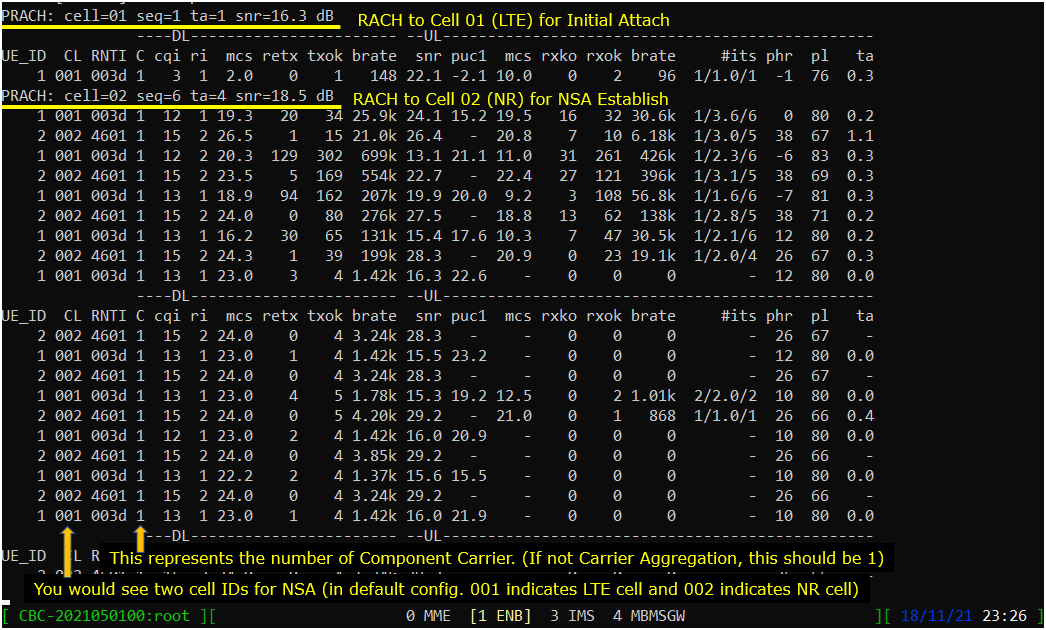
Press [Enter] key to stop the trace logging. When you want to use another command, you need to stop 't' command by pressing the enter key and get back to prompt as shown below.
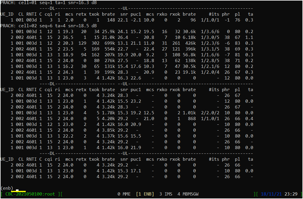
While UE is in connected status, you can get the connection information with the command 'ue' in (enb) as shown below. If the call is in idle status, you would not get any information.

you can get the connection information with the command 'ue' in (mme) as shown below. You would get this result once UE complete the attach. One important information you would get is the IP address assigned to the UE.

Log Analysis
In this section, you will see how to confirm if UE is established with NSA. I will skip the initial registration part and focus only on NSA setup. Refer to the tutorial OutOfBox Test LTE if you are not familiar with the log for initial attach
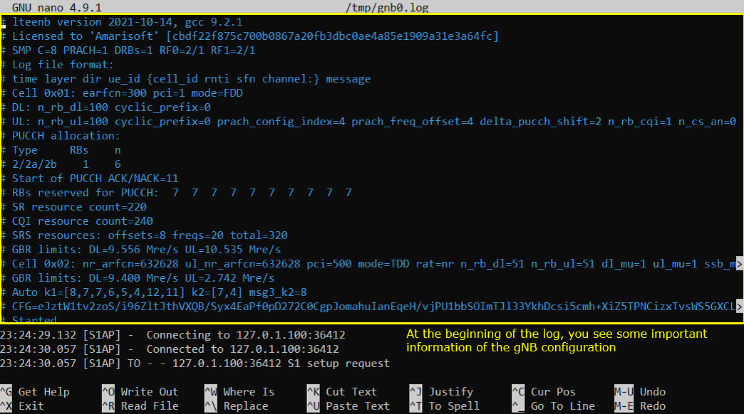
Open /tmp/gnb0.log using any text editor. I am using nano in this tutorial. You will see various high level information (meta data) at the beginning of the file. This is useful high level information. Check out this tutorial to the details on this meta data.
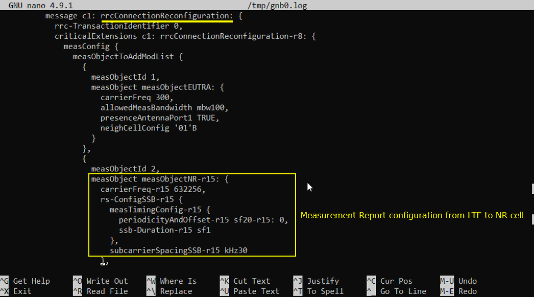
After the attach to LTE is completed, you should see that eNB send Measurement Report Configuration for NR cell as shown below. If you don't see this message, it is highly likely that UE does not notify NR support in UE capability or UE support NR but does not support band combination you specified in the configuration file.
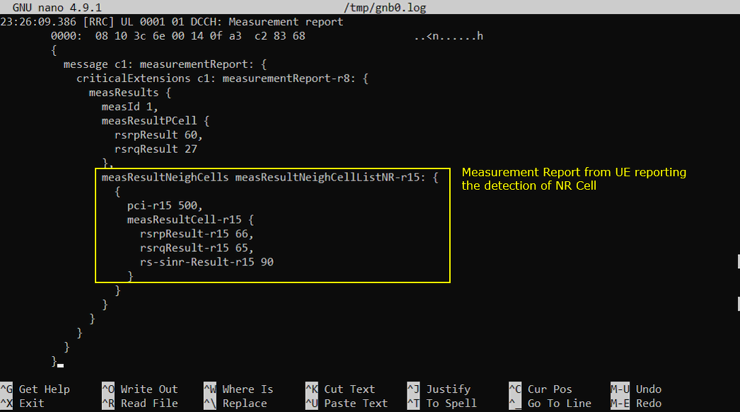
If you support the LTE-NR band combination specified above and NR cell is properly configured, you should see the measurement report for NR as shown below. If UE does not send this measurement report, eNB does not send RrcConnectionReconfiguration message for NR addition. This is one of the most common cause for NSA failure.
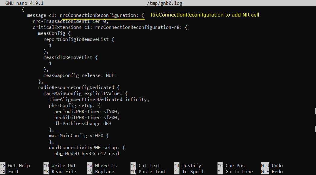
If the measurement report from UE is recieved, (in most case) eNB send RrcConnectionReconfiguration to add NR cell as shown below.
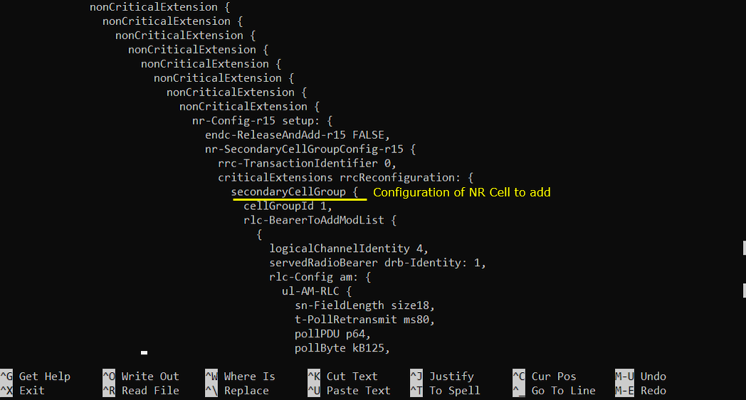
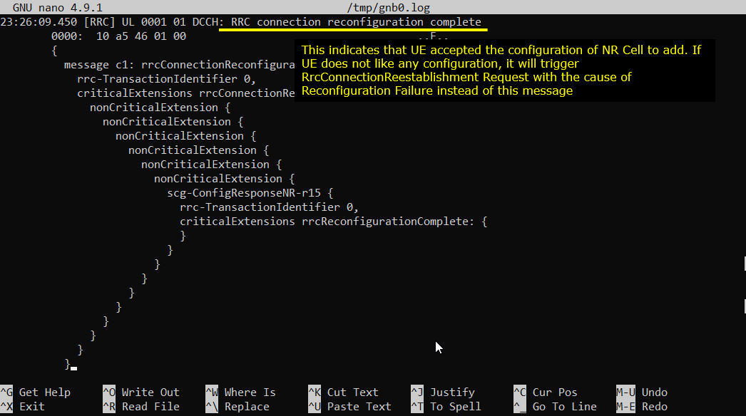
If UE received the RrcConnectionReconfiguration and processed it successfully, UE send RrcConnectionReconfigurationComplete message.
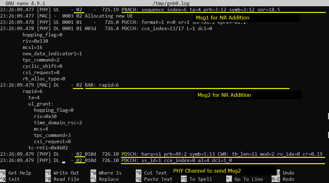
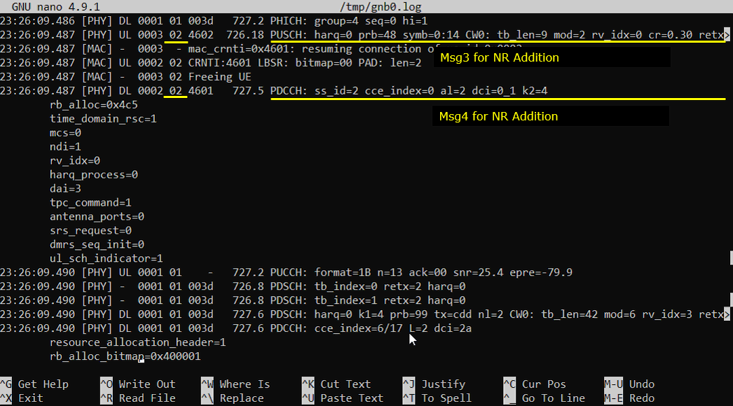
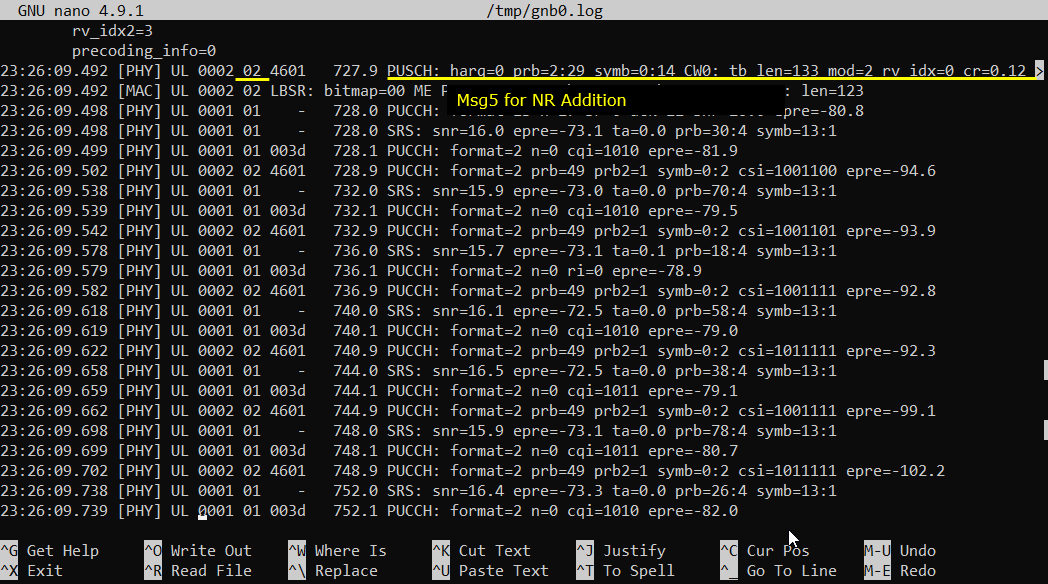
Now UE and Network perform RACH procedure to establish the connection to NR cell. This RACH procedure is 5 step process as shown below. If the process fails any of these steps, NSA establish fails.
Generating Traffic
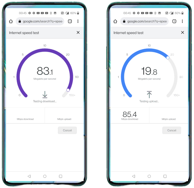
Once UE established NSA and in connected mode, you may generate IP traffic for throughput test. There are many different ways to generate IP traffic. In this tutorial, I simply opened up a browser on UE and visit speedtest site.
Analysis in Screen during traffic test
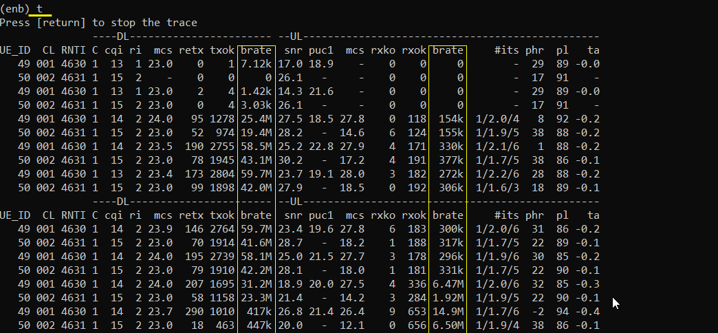
During the traffic test, we usually check some status in Screen window for checking throughput or troubleshoot. Followings are three most common command that we use for check up. If you are not familiar with the meaning or interpretation of these commands. Refer to Command Line command tutorial.
With t command, you can check various things. For the quick check on connectivity, just checking the throughput indicated by 'brate' columnwould be good enough. For further details on how to interpret this and how to use the information for troubleshooting, check out this tutorial.
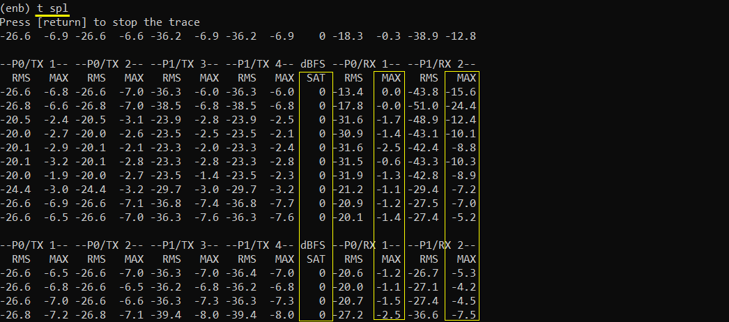
If you think you have any power related issues for example TX and RX power, run 't spl'. This is especially useful to troubleshoot the reciever power related issue. For further details on how to interpret this and how to use the information for troubleshooting, check out this tutorial.
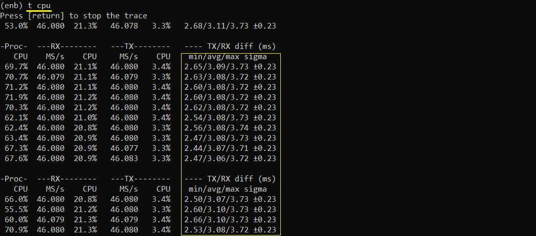
If you think you have issues related to performance (e.g, timing issue or overflow issue), run 't cpu'. This is especially useful to troubleshoot the case when you have 'overflow' issue. For further details on how to interpret this and how to use the information for troubleshooting, check out this tutorial.
Traffic Analysis on WebGUI
This is an optional section. You may try high throughput test and analyze it with WebGUI. If you are not familiar with how to setup and use WebGUI, refer to the tutorial : WebGUI.
What kind of Analsys to be checked is up to you, but a few examples shown in this tutorial would be the most common analysis you may check.
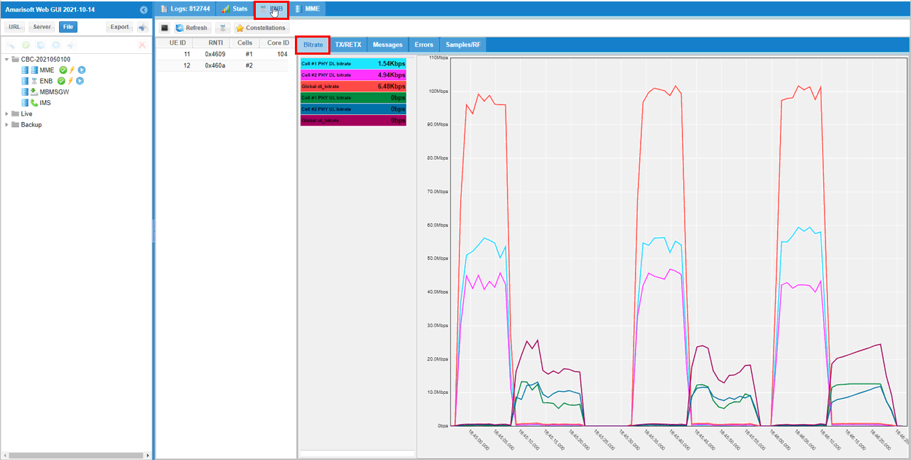
First thing you may want to check out is the throughput plot. The tool menu on the analysis screen would vary depending on the software version you are using an older version of the software, you would get the plot window right away when you clicking on [ENB] button. Hit on [Bitrate] tab to get the throughput plot.
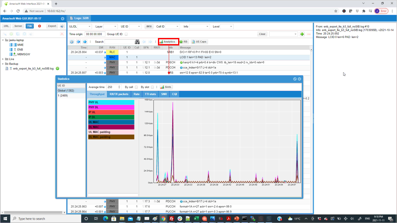
If you are using the relatively recent version, hit [Analysis] button first and then you get the plot window. Select [Throughput] tab to get the throughput plot.
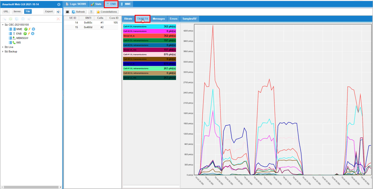
If you hit [TX RETX] tab, you will get the plots for the count of retransmitted packet. This plot shows how many packets failed to be decoded by the reciever and retransmitted.
In addition to these plots mentioned above, there are various additional analysis features are supported by WebGUI. If you want to know more about all other features of WebGUI, check out this tutorial.
Test 2: 6LTE CA+ Single NR
This is a kind of advanced test of NSA and I assume that the readers are already familiar with basic operations and overall verification procedures explained in Test 1. With that assumption, I would mainly focus on RAN side configuration and verification only. You can follow the procedure in Test 1 for user traffic.
- The best option is that you have 7 sdr cards.
- If you don't have enough number of sdr cards, you may put multiple cells in one sdr card if the requency and RAT requirement is met as mentioned in this tutorial.
Configuration
The configuration for this test is gnb-6LTE-1NR-nsa.cfg which is cbased on gnb-nsa.cfg. It may look complicated but it is just repetition of the same structure with minor modifications.
Following is the configurations for 6 LTE cells.
1st LTE Cell
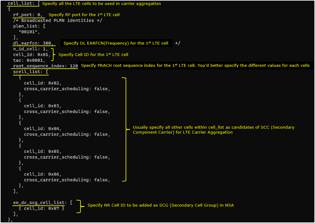
1st LTE cell is mapped to rf_port 0 and configured for FDD. dl_earfcn is set to 300. 5 LTE cells (cell id 2,3,4,5,6) are configured as SCC (Secondary Component Carrier) and one NR cell (cell id 7) is configured as SCG(Secondary Cell Group).
2nd LTE Cell
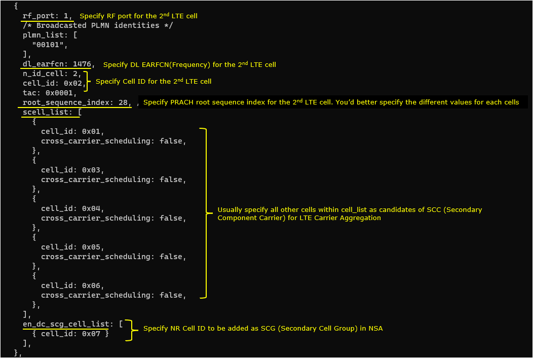
2nd LTE cell is mapped to rf_port 1and configured for FDD. dl_earfcn is set to 1476. 5 LTE cells (cell id 1,3,4,5,6) are configured as SCC (Secondary Component Carrier) and one NR cell (cell id 7) is configured as SCG(Secondary Cell Group).
3rd LTE Cell
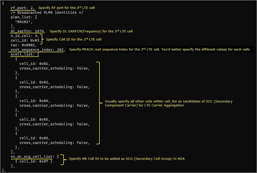
3rd LTE cell is mapped to rf_port 2and configured for FDD. dl_earfcn is set to 1674. 5 LTE cells (cell id 1,2,4,5,6) are configured as SCC (Secondary Component Carrier) and one NR cell (cell id 7) is configured as SCG(Secondary Cell Group).
4th LTE Cell
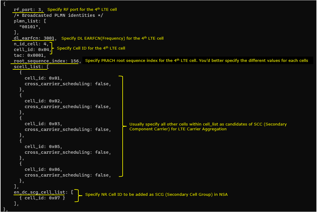
4th LTE cell is mapped to rf_port 3and configured for FDD. dl_earfcn is set to 3001. 5 LTE cells (cell id 1,2,3,5,6) are configured as SCC (Secondary Component Carrier) and one NR cell (cell id 7) is configured as SCG(Secondary Cell Group).
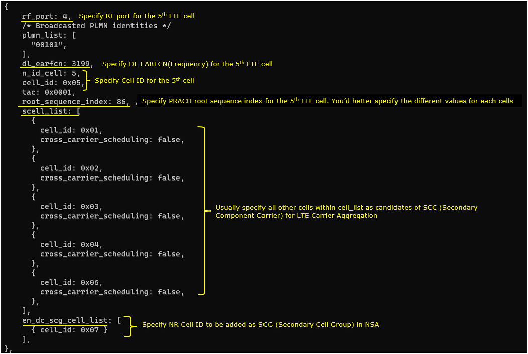
5th LTE Cell
5th LTE cell is mapped to rf_port 4and configured for FDD. dl_earfcn is set to 3199. 5 LTE cells (cell id 1,2,3,4,6) are configured as SCC (Secondary Component Carrier) and one NR cell (cell id 7) is configured as SCG(Secondary Cell Group).
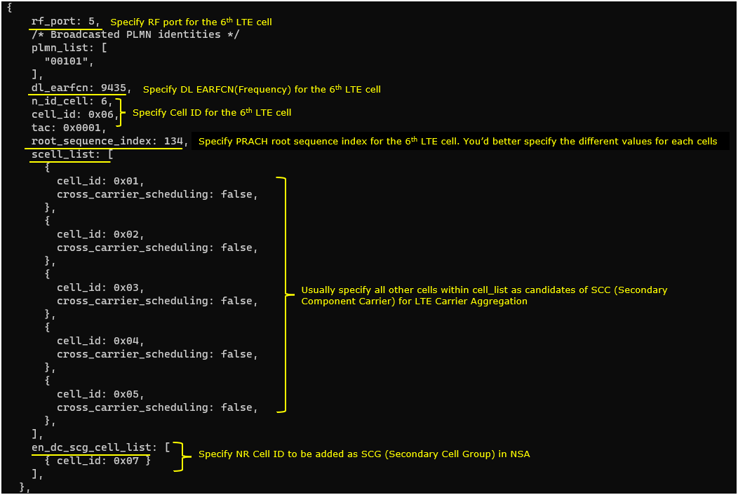
6th LTE Cell
6th LTE cell is mapped to rf_port 5and configured for FDD. dl_earfcn is set to 9435. 5 LTE cells (cell id 1,2,3,4,5) are configured as SCC (Secondary Component Carrier) and one NR cell (cell id 7) is configured as SCG(Secondary Cell Group).
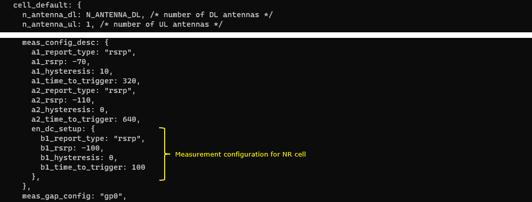
Common to AllLTE Cell
For all LTE cell,the measurement configuration for NR cell (Event B1)is configured. The presence of this configuration indicates Measurement Report from UE is required to trigger NR Addition.
NRCell
One NR cell is configured and it is mapped to rf_port 6. It is configured as TDD, band n78 and dl_nr_arfcn 636666.

Perform the Test
Check cell phy and cell commandoutput, and see if all the cells are configured as intended.


Run 't' command and get UE attached and wait until NR cell is added. (If you have any issues with NR addition, refer to troubleshoot section)

Log Analysis
Check out every details in the log. It will help you with understanding LTE CA and NSA protocol and troubleshoot process.
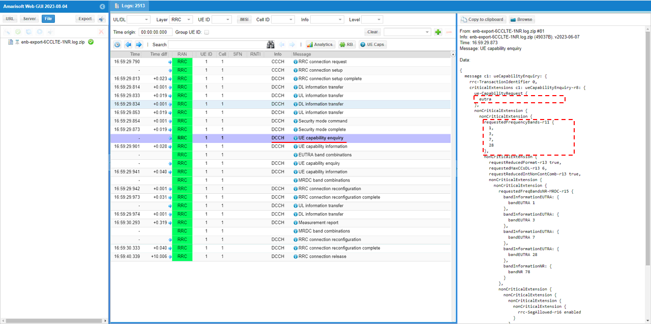
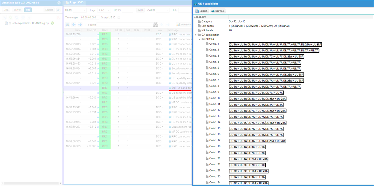
First thing you need to check in any carrier aggregation test is UE capability enquiry. You see an UE capability enquiry for LTE band 1, 3, 7, 28was sent.
Check out the contents of UE capability information message from UE. It would be easier to check it out with UE capability table rather than looking into the UE capability information RRC message itself. Ensure that the UE (DUT) supports LTE CA
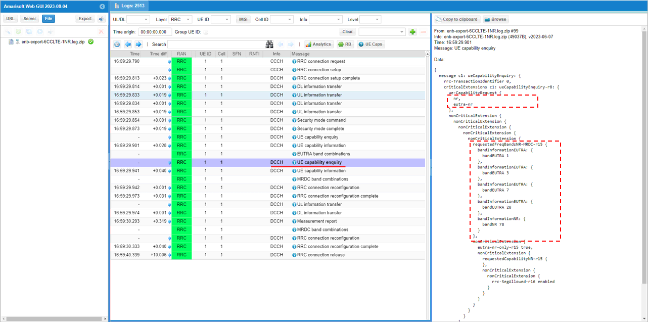
For NSA capability check, another UE capability enquiry was sent with nr n78 and lte b1,3,7,28.
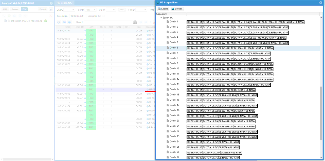
Check out the contents of UE capability information message from UE. It would be easier to check it out with UE capability table rather than looking into the UE capability information RRC message itself. Ensure that the UE (DUT) supports ENDC
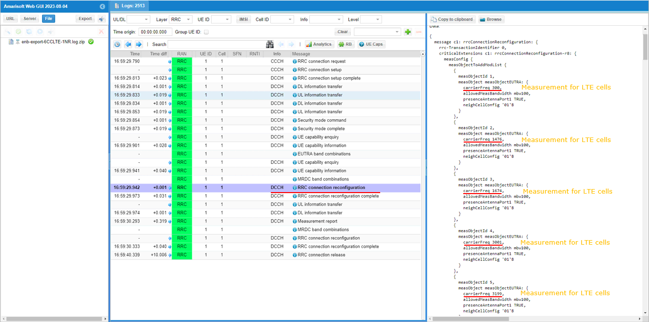
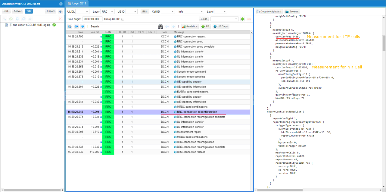
If UE capability information carries the band combination that is necessary to establish the desired carrier aggregation and NSA (endc), eNB configures measurement report. In this example, the measurement for carrierFreq 300,1476,1674,3001,3199,9435 are configured.
Measurement for NR cell with the carrierfreq of 633696 is configured as well. The frequency set is SSB frequency of the target NR cell. Then report configuration for even B1 is set.
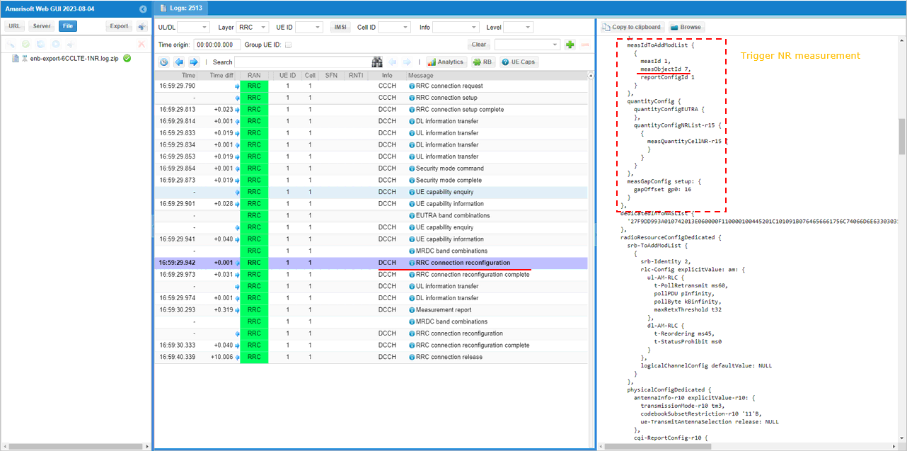
Finally measObjectId 7(NR measurement in this configuration) and reportConfigId 1(Event B1 in this configuration) is triggered.
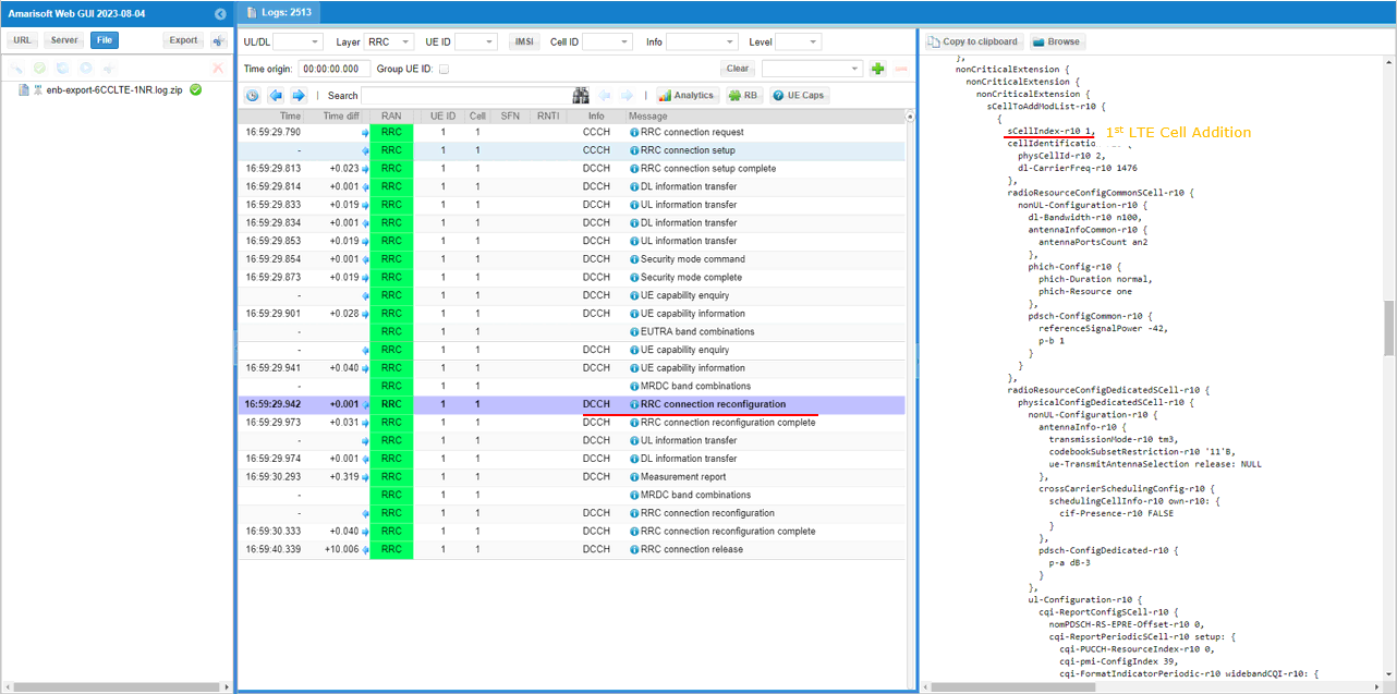
In the same RRCconnectionReconfiguration message, LTE cell id 2 is added as SCC 1(sCellIndex-r10 1).
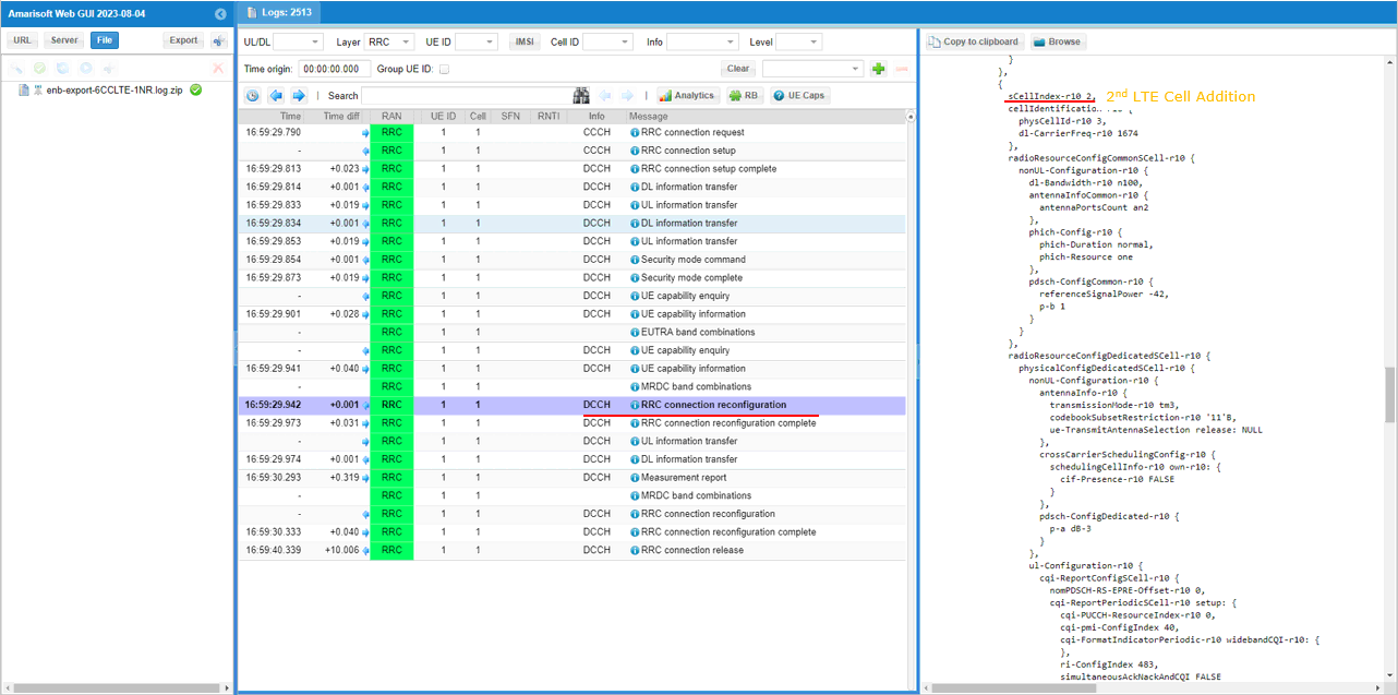
In the same RRCconnectionReconfiguration message, LTE cell id 3is added as SCC 2(sCellIndex-r10 2).
In the same RRCconnectionReconfiguration message, LTE cell id 4is added as SCC 3(sCellIndex-r10 3).
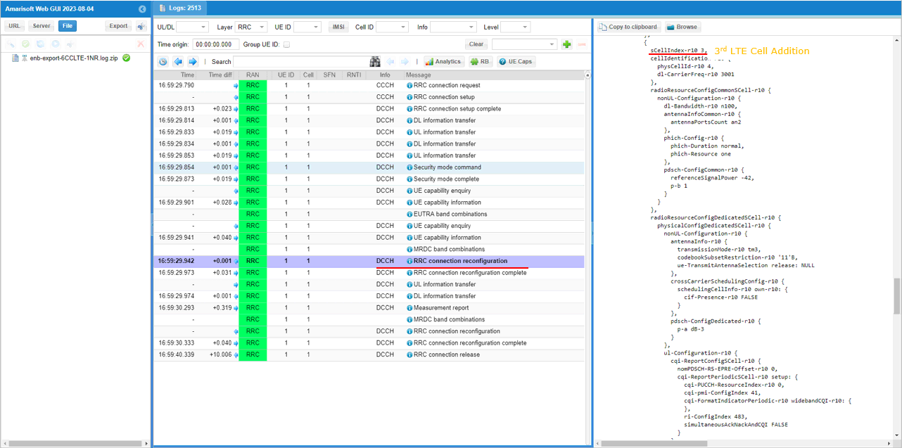
In the same RRCconnectionReconfiguration message, LTE cell id 5is added as SCC 4(sCellIndex-r10 4).
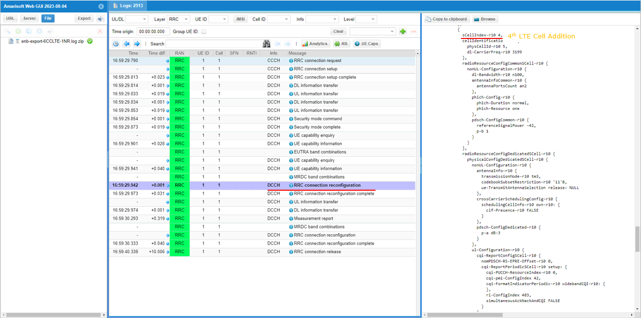
In the same RRCconnectionReconfiguration message, LTE cell id 6is added as SCC 5(sCellIndex-r10 5).
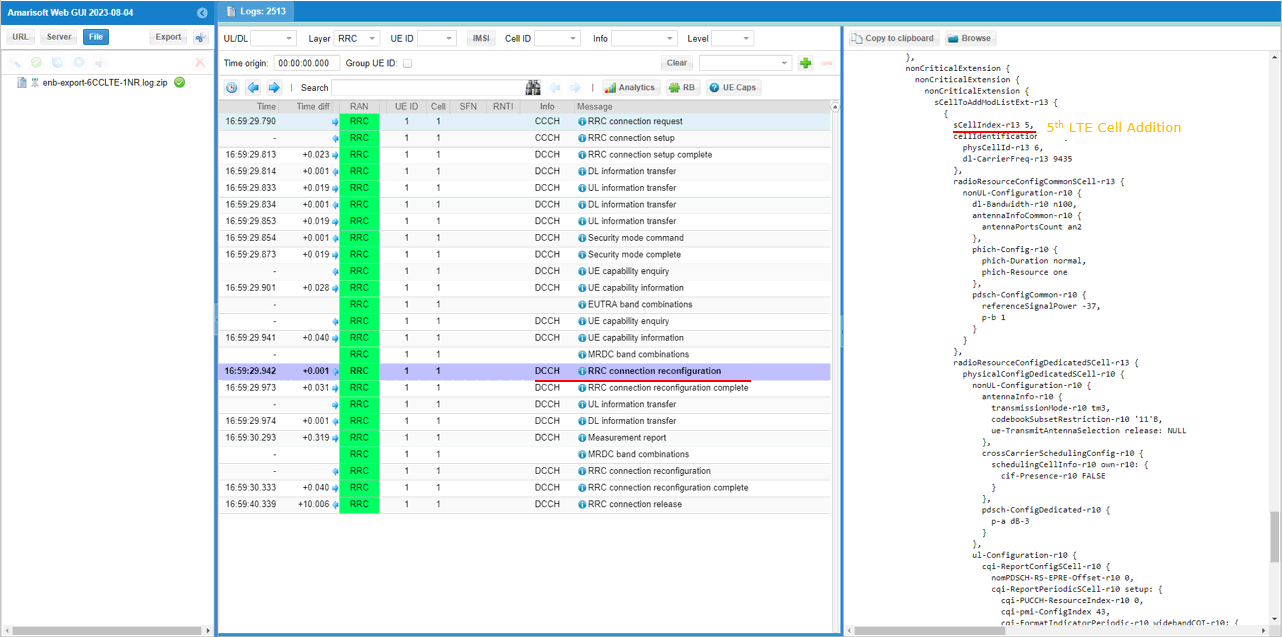
In the same RRCconnectionReconfiguration message, nr0RadioBearerConfig1-r15 is configured.
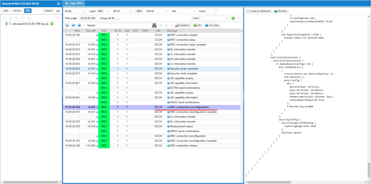
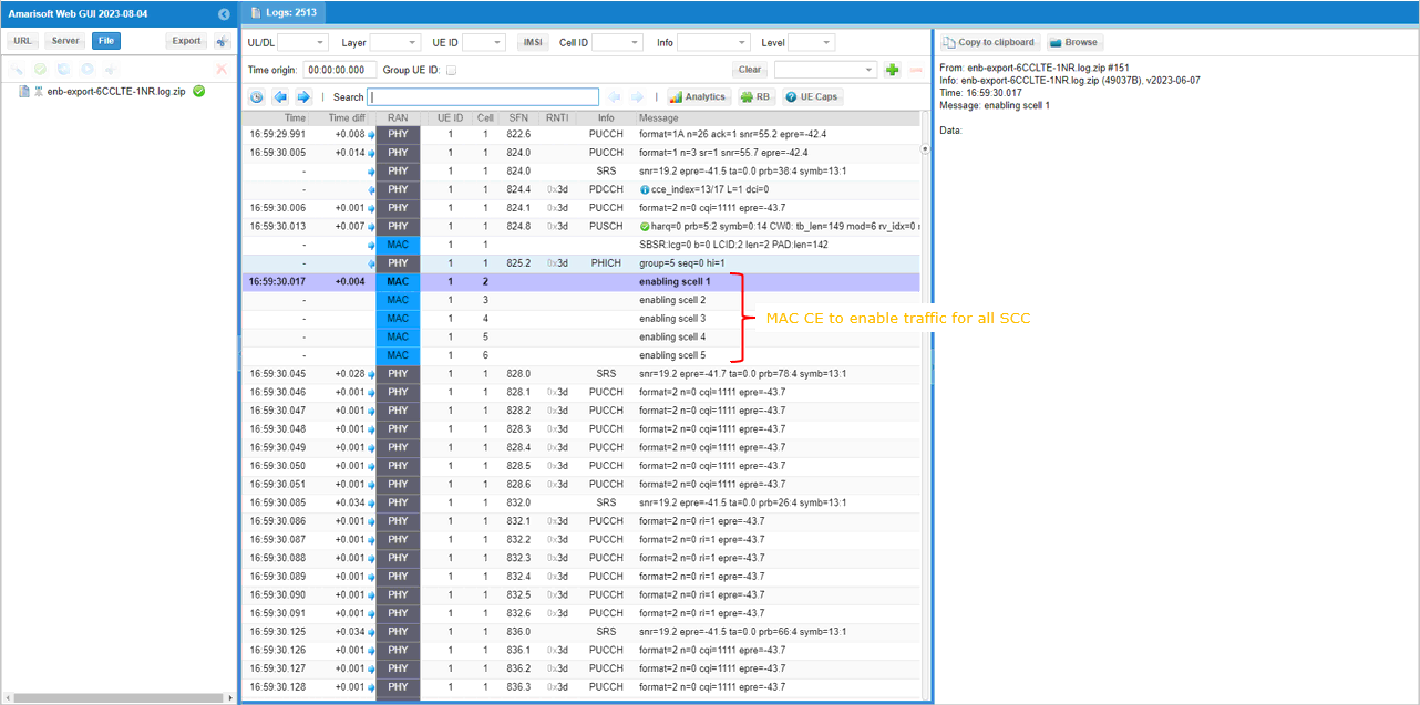
Once all the RRC processes are processed properly, MAC CE to enable SCC 1,2,3,4,5 are sent.
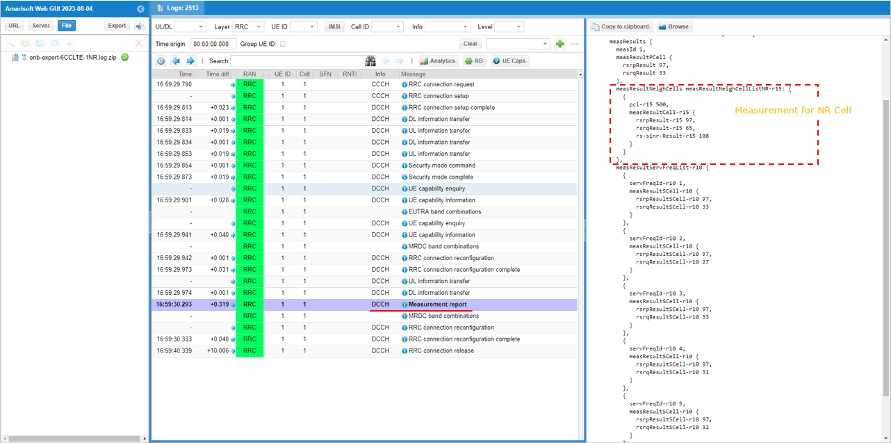
UE is expected to send measurement report for NR cell. after setting up LTE Carrier Aggregation
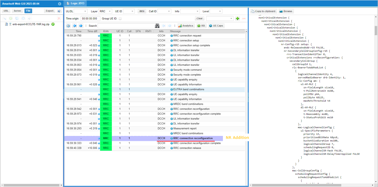
Once eNB recieves the measurement report for NR cell, eNB send RRCconnectionReconfiguration to establish NSA(endc).
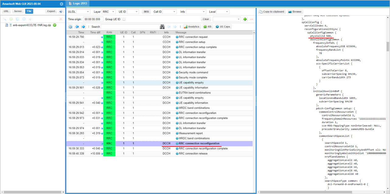
You can confirm that n78 and PCI 500 NR cell is added as SCG (Secondary Cell Group)
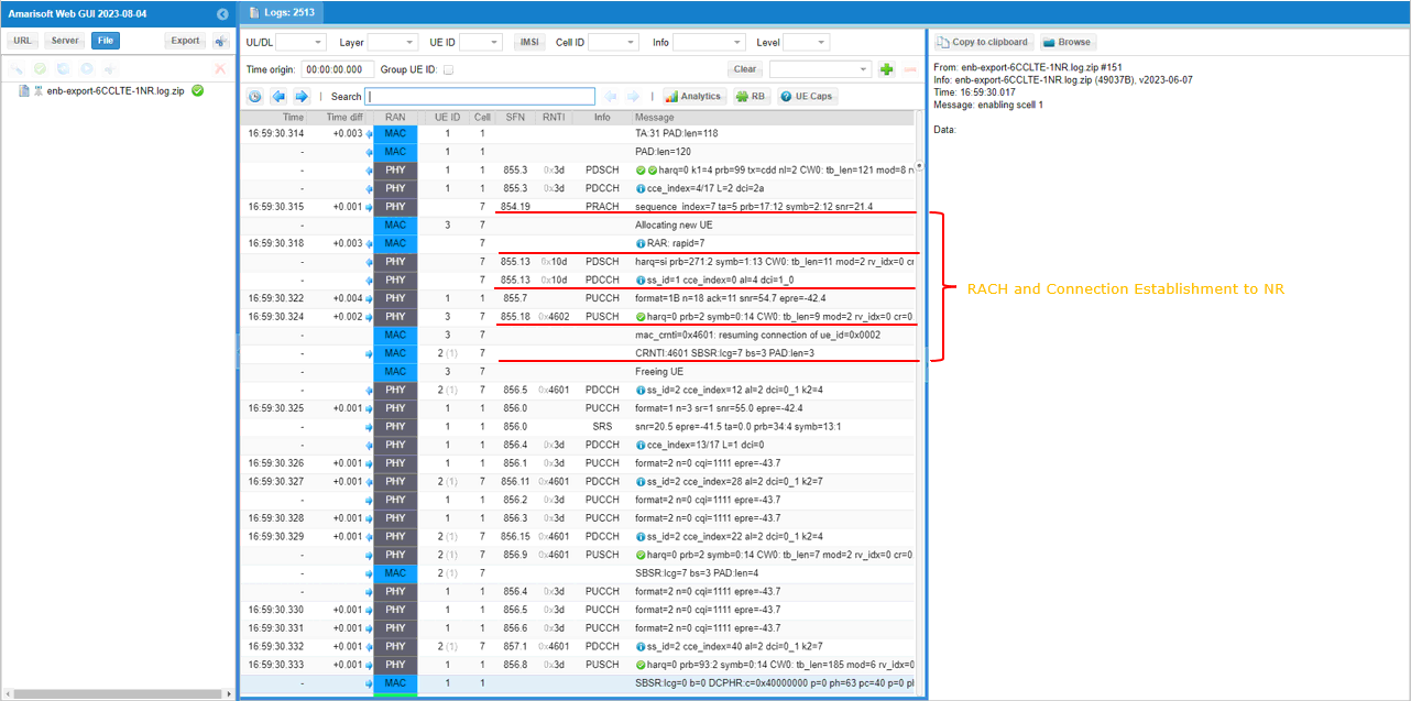
You can confirm the addition of NR cell by checking if RACH process in NR is completed. This is an important step since this is where NSA setup failure happens frequently.
Test 3: 5LTE CA(FDD + TDD)+ Single NR
This is a kind of advanced test of NSA and I assume that the readers are already familiar with basic operations and overall verification procedures explained in Test 1. With that assumption, I would mainly focus on RAN side configuration and verification only. You can follow the procedure in Test 1 for user traffic.
- The best option is that you have 6sdr cards.
- If you don't have enough number of sdr cards, you may put multiple cells in one sdr card if the requency and RAT requirement is met as mentioned in this tutorial.
Configuration
The configuration for this test is gnb-cc-mix_TDD_FDD-nsa.cfg which is cbased on gnb-nsa.cfg. It may look complicated but it is just repetition of the same structure with minor modifications.
Following is the configurations for 5LTE cells. The key point to be noticed in this configuration is that not all LTE cells uses the same duplex pattern. It is mixture of FDD and TDD. Some of them are using FDD and some of them are using TDD.
Global Parameters
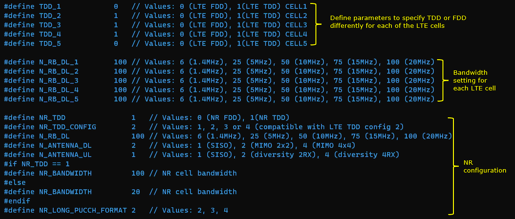
At the beginning, several flags (parameters) are added to let user to apply duplex mode and bandwidth differently for each LTE cells. These parameters are needed because the cells in carrier aggregation in this tutorial is mixture of FDD and TDD.
1st LTE Cell
Then configure the physical parameters of the first LTE cell. This cell is mapped to rf_port 0. This cell is configured for FDD and dl_earfcn is 800.

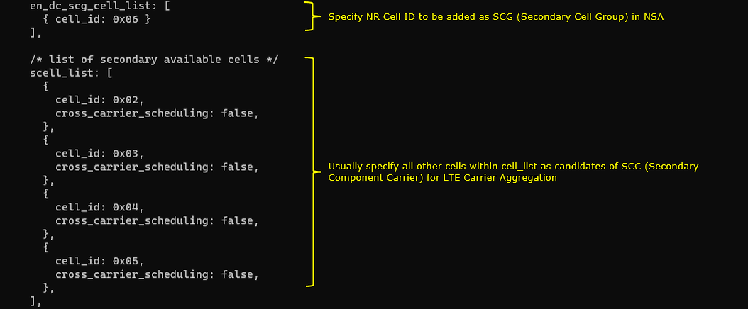
One NR cell (cell id 6) is configured as SCG(Secondary Cell Group) and 4 LTE cells (cell id 2,3,4,5) are configured as SCC(Secondary Component Carrier).
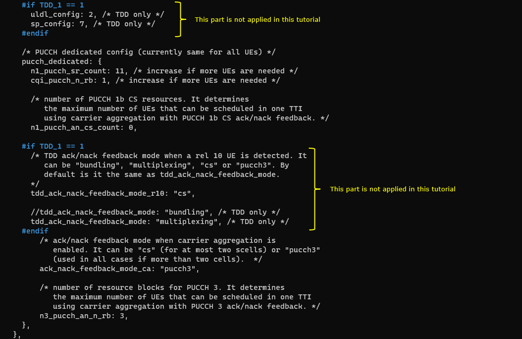
This cell is configured as FDD. so TDD specific configuration is not applied.
2nd LTE Cell
Next, configure the physical parameters of the 2ndLTE cell. This cell is mapped to rf_port 1. This cell is configured for TDD and dl_earfcn is 47290.

One NR cell (cell id 6) is configured as SCG(Secondary Cell Group) and 4 LTE cells (cell id 1,3,4,5) are configured as SCC(Secondary Component Carrier).
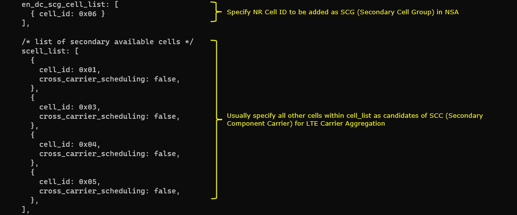
This cell is configured as TDD. uldl_config is set to 2 and sp_config is set to 7. tdd_ack_nack_feedback_mode_r10 is set to "cs" and tdd_ack_nack_feedback_mode is set to "multiplexing"
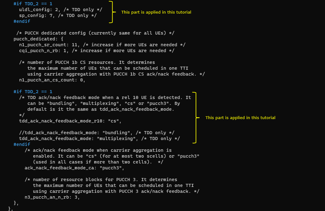
3rd LTE Cell
Next, configure the physical parameters of the 3rdLTE cell. This cell is mapped to rf_port 2. This cell is configured for TDD and dl_earfcn is 47488.

One NR cell (cell id 6) is configured as SCG(Secondary Cell Group) and 4 LTE cells (cell id 1,2,4,5) are configured as SCC(Secondary Component Carrier).
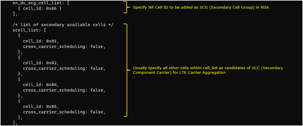
This cell is configured as TDD. uldl_config is set to 2 and sp_config is set to 7. tdd_ack_nack_feedback_mode_r10 is set to "cs" and tdd_ack_nack_feedback_mode is set to "multiplexing"
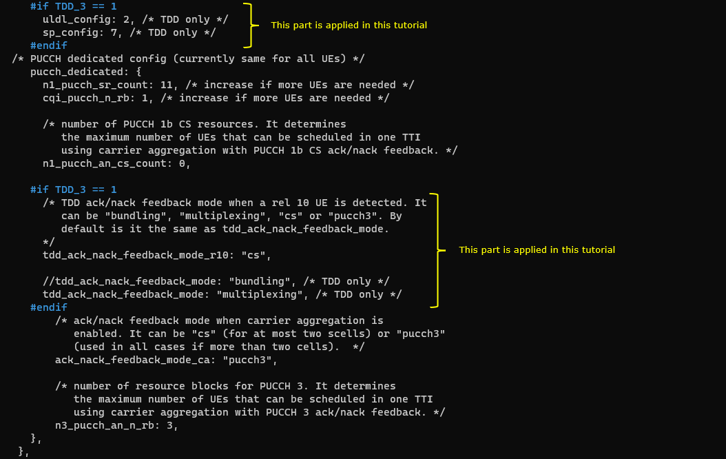
4th LTE Cell
Next, configure the physical parameters of the 4th LTE cell. This cell is mapped to rf_port 3. This cell is configured for TDD and dl_earfcn is 47686.

One NR cell (cell id 6) is configured as SCG(Secondary Cell Group) and 4 LTE cells (cell id 1,2,3,5) are configured as SCC(Secondary Component Carrier).
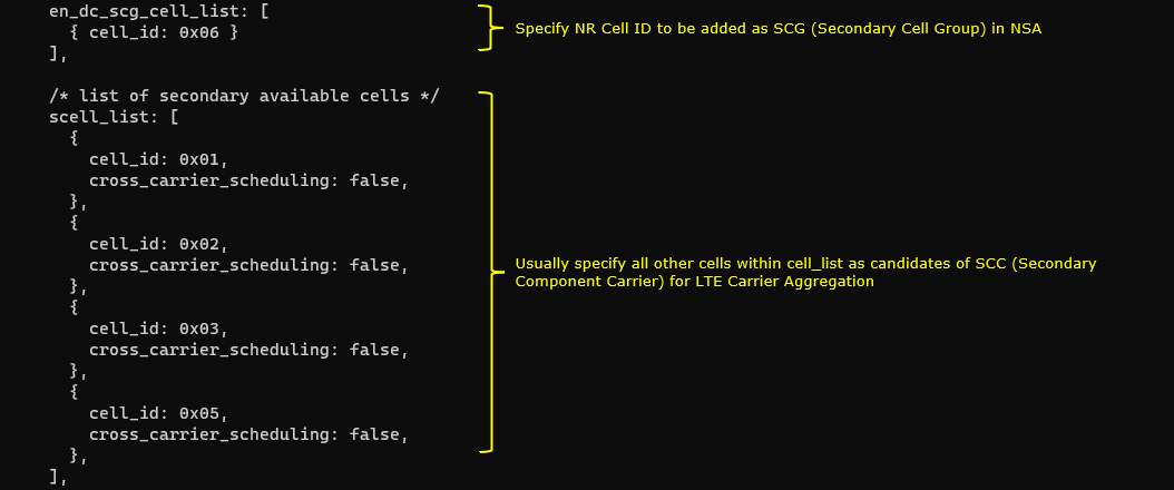
This cell is configured as TDD. uldl_config is set to 2 and sp_config is set to 7. tdd_ack_nack_feedback_mode_r10 is set to "cs" and tdd_ack_nack_feedback_mode is set to "multiplexing"
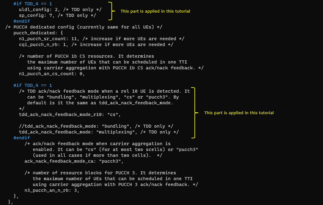
5th LTE Cell
Last for LTE cell, configure the physical parameters of the 5th LTE cell. This cell is mapped to rf_port 4. This cell is configured for FDD and dl_earfcn is 66836.

One NR cell (cell id 6) is configured as SCG(Secondary Cell Group) and 4 LTE cells (cell id 1,2,3,4) are configured as SCC(Secondary Component Carrier).
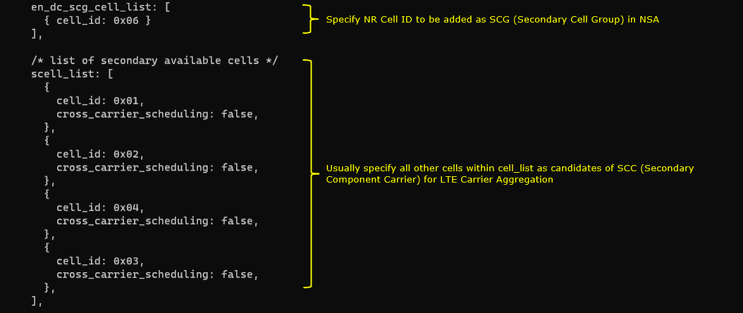
This cell is configured as FDD. so TDD specific configuration is not applied.
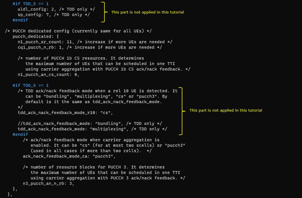
NRCell
Now, configure NR cell to be used for NSA setup. NR Cell is configured to TDD, band n78 and dl_nr_arfcn 627300.

Common to All LTE Cell
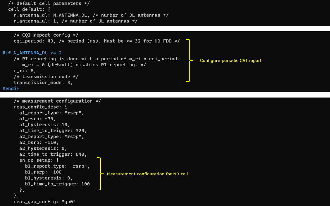
For configuration that are applied to all of the LTE cell (cell_default), CSI report is set to periodic, Transmission mode is TM3 and Measurement Report (B1) is configured meaning that a proper measurement report is required to initiate NSA setup.
Perform the Test
Check cell phy and cell commandoutput, and see if all the cells are configured as intended.

Run 't' command and get UE attached and wait until NR cell is added. (If you have any issues with NR addition, refer to troubleshoot section)

Log Analysis
Check out every details in the log. It will help you with understanding LTE CA and NSA protocol and troubleshoot process.
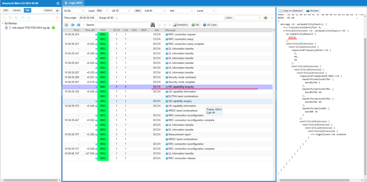
First thing you need to check in any carrier aggregation test is UE capability enquiry. You see an UE capability enquiry for LTE band 2, 46, 66 was sent.
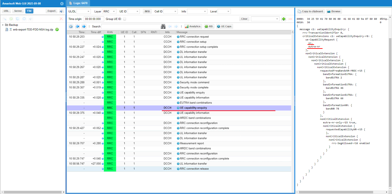
For NSA capability check, another UE capability enquiry was sent with nr n78 and lte b2,46,66.
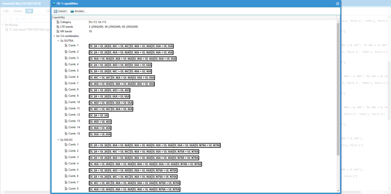
Check out the contents of UE capability information message from UE. It would be easier to check it out with UE capability table rather than looking into the UE capability information RRC message itself. Ensure that the UE (DUT) supports LTE CA and NSA band combination that you want to establish.
If UE capability information carries the band combination that is necessary to establish the desired carrier aggregation and NSA (endc), eNB configures measurement report. In this example, the measurement for carrierFreq 800,47290,47488,47686,65535 are configured.
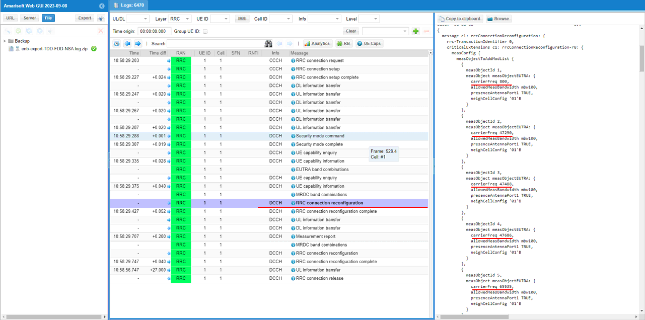
Measurement for NR cell with the carrierfreq of 624288is configured as well. The frequency set is SSB frequency of the target NR cell.
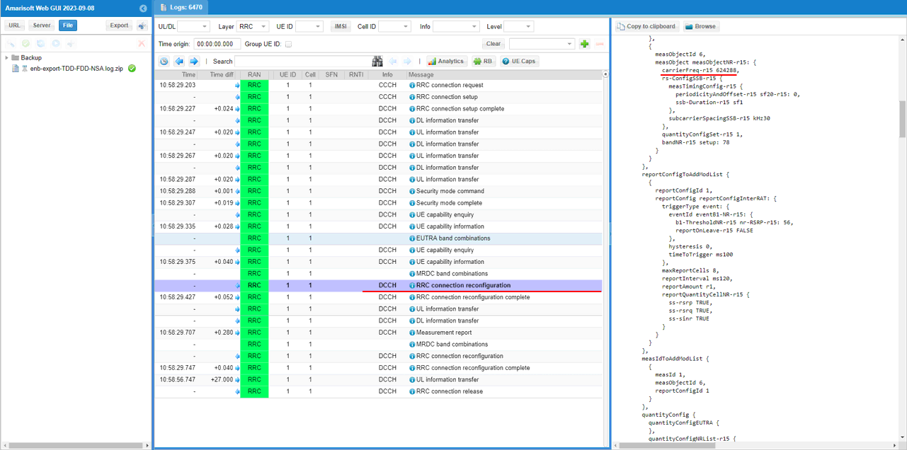
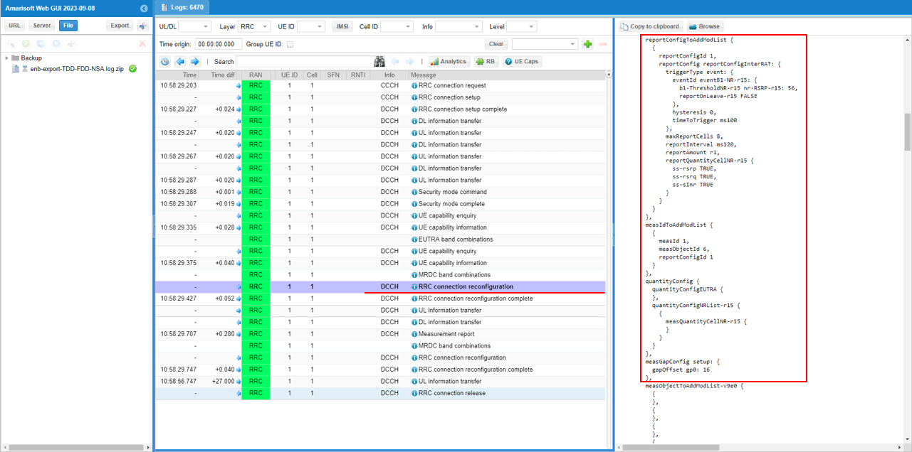
Then report configuration for even B1 is set. FinallymeasObjectId 6(NR measurement in this configuration) and reportConfigId 1(Event B1 in this configuration) is triggered.
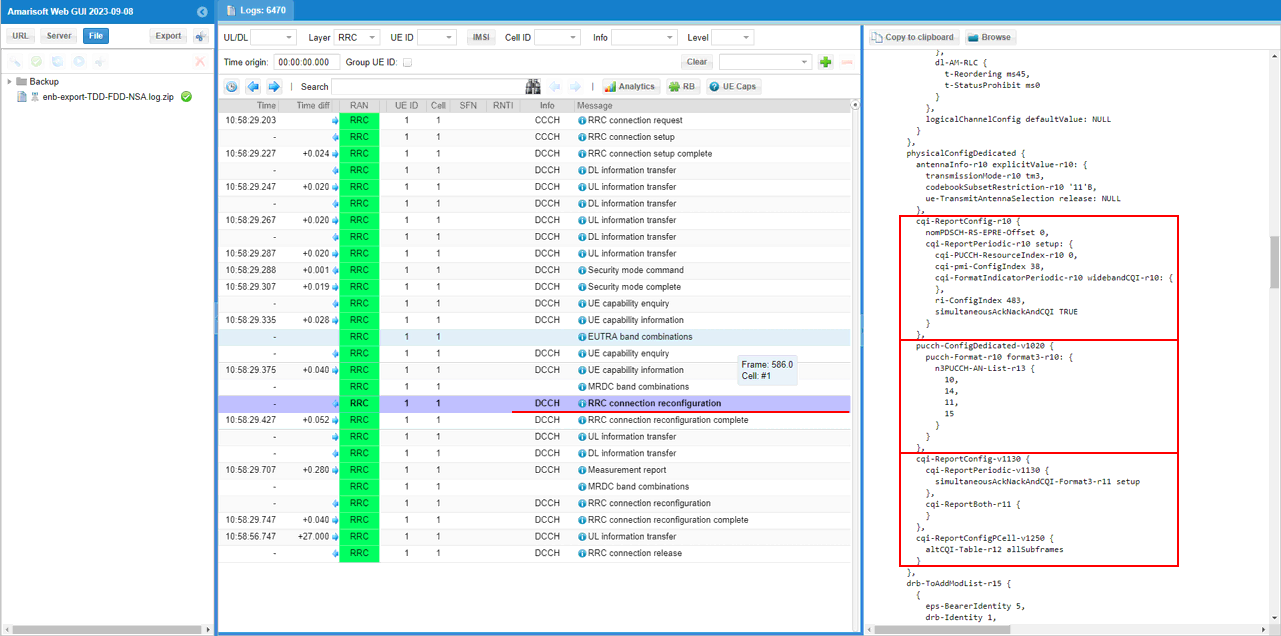
In the same RRCconnectionReconfiguration message, csi report configuration for all the subcarriers of LTE cells are configured.
In the same RRCconnectionReconfiguration message, LTE cell id 2 is added as SCC 1(sCellIndex-r10 1).
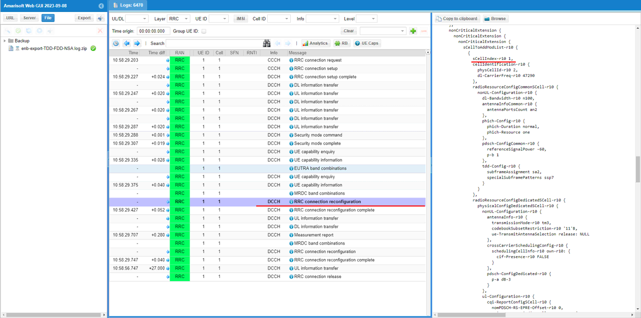
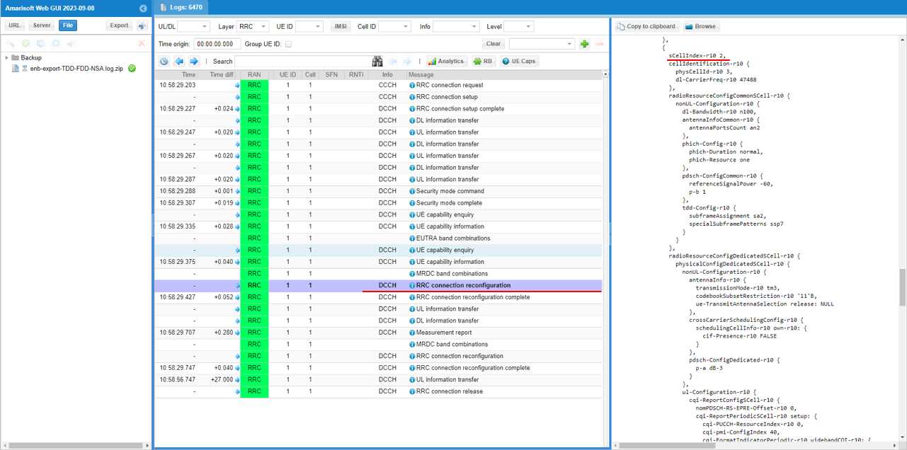
In the same RRCconnectionReconfiguration message, LTE cell id 3is added as SCC 2(sCellIndex-r10 2).
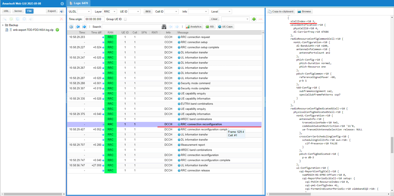
In the same RRCconnectionReconfiguration message, LTE cell id 4is added as SCC 3(sCellIndex-r10 3).
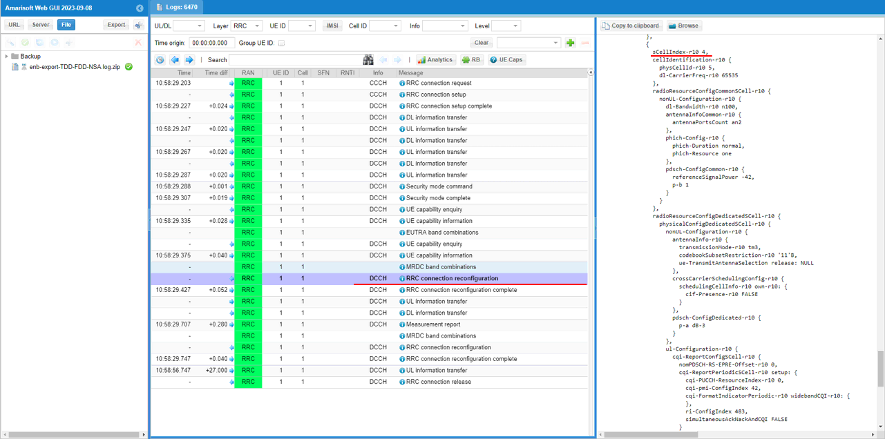
In the same RRCconnectionReconfiguration message, LTE cell id 5is added as SCC 4(sCellIndex-r10 4).
In the same RRCconnectionReconfiguration message, nr0RadioBearerConfig1-r15 is configured.
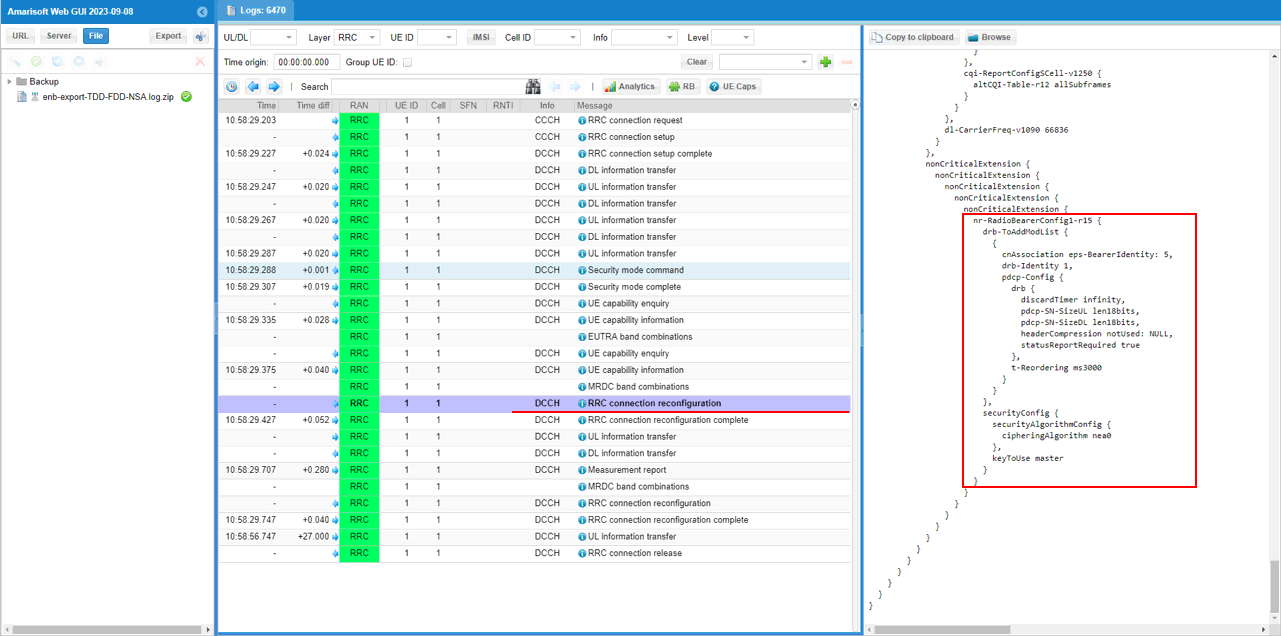
UE is expected to send measurement report for NR cell.
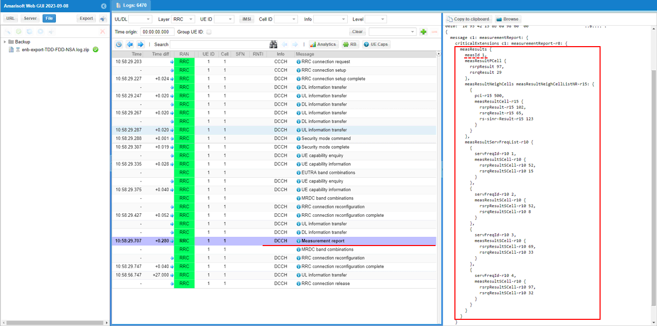
Once eNB recieves the measurement report for NR cell, eNB send RRCconnectionReconfiguration to establish NSA(endc).
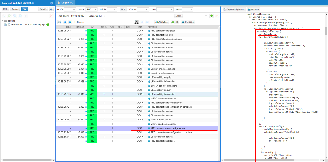
You can confirm that n78 NR cell is added as SCG (Secondary Cell Group)
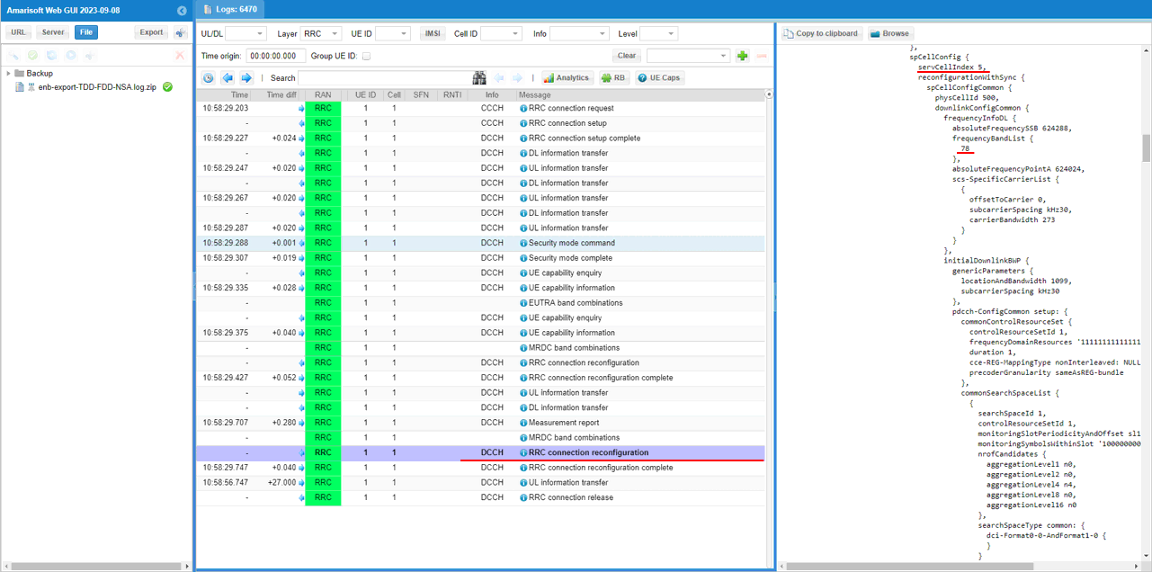
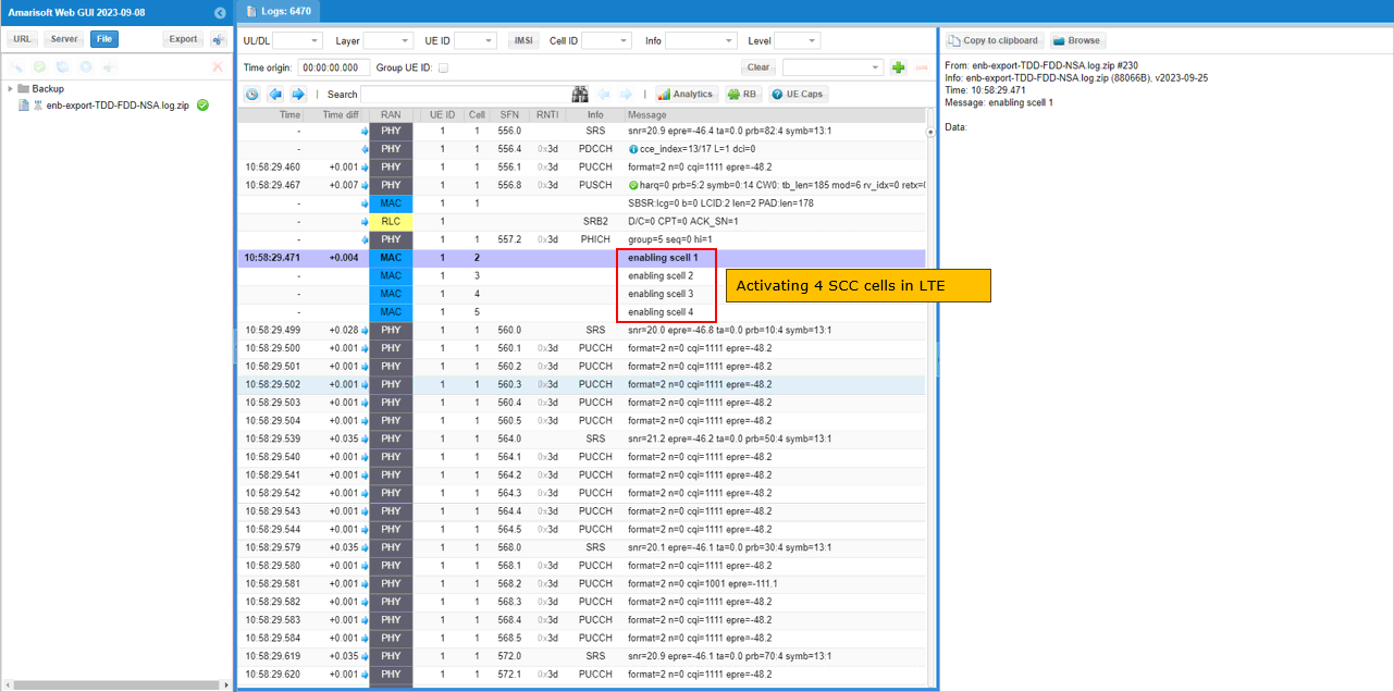
Once all the RRC processes are processed properly, MAC CE to enable SCC 1,2,3,4 are sent.
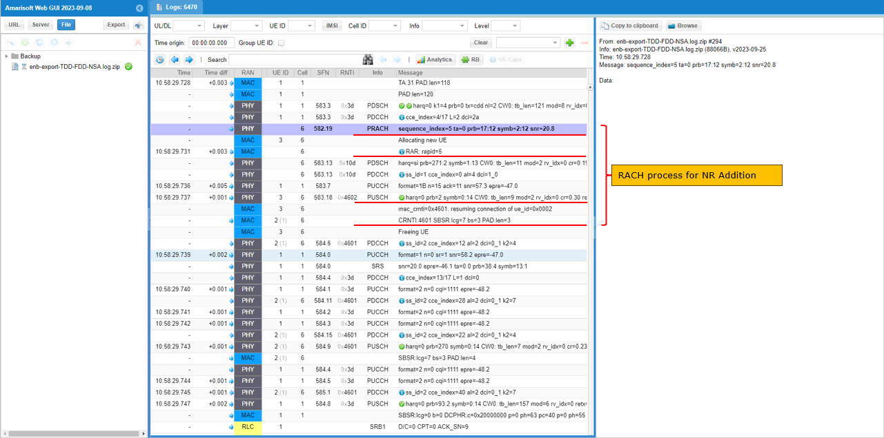
You can confirm the addition of NR cell by checking if RACH process in NR is completed. This is an important step since this is where NSA setup failure happens frequently.
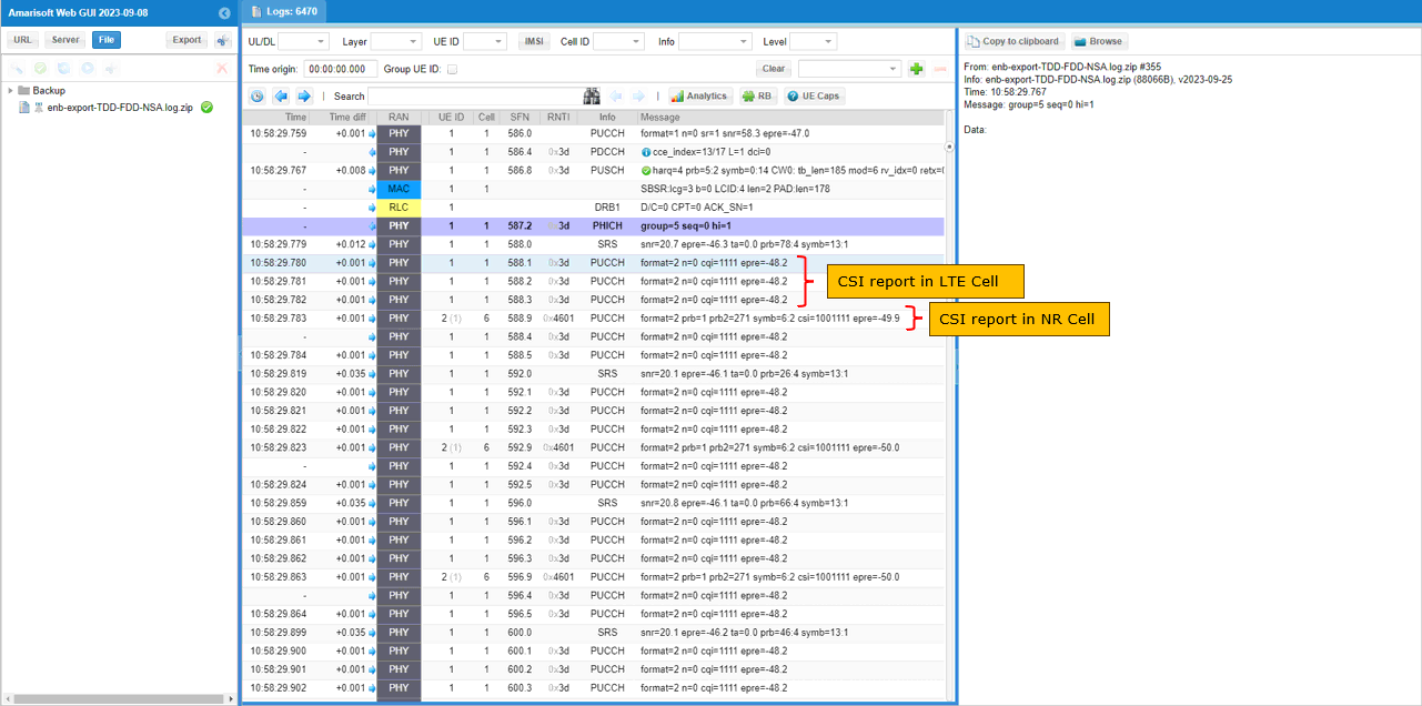
Once all LTE carrier aggregation and NR addition is completed, traffic flows and csi report are received for both LTE and NR as set in the configuration file.
RRC / NAS Signaling
: This section is to show you the overall structure of important Rrc messages and Information IE (IE) that are related to this tutorial. It is not intended to describe the details on every RRC/NAS Information elements. With the overall structure and key IEs shown here, it hope it would be easier / clearer to go through the sample log provided in this tutorial or any logs that you captured from your own test setup or live network.
rrcConnectionReconfiguration for NR Addition
: This is the RRC message sent by eNB (LTE) to add NR. (
message c1: rrcConnectionReconfiguration: {
rrc-TransactionIdentifier 0,
criticalExtensions c1: rrcConnectionReconfiguration-r8: {
....
nonCriticalExtension {
nonCriticalExtension {
nonCriticalExtension {
nonCriticalExtension {
nonCriticalExtension {
nonCriticalExtension {
nonCriticalExtension {
nonCriticalExtension {
nr-Config-r15 setup: {
endc-ReleaseAndAdd-r15 FALSE,
nr-SecondaryCellGroupConfig-r15 {
rrc-TransactionIdentifier 0,
criticalExtensions rrcReconfiguration: {
secondaryCellGroup {
cellGroupId 1,
rlc-BearerToAddModList {
...
mac-CellGroupConfig {
...
physicalCellGroupConfig {
pdsch-HARQ-ACK-Codebook dynamic
},
spCellConfig {
servCellIndex 1,
reconfigurationWithSync {
spCellConfigCommon {
physCellId 500,
downlinkConfigCommon {
frequencyInfoDL {
absoluteFrequencySSB 632256,
frequencyBandList {
78
},
absoluteFrequencyPointA 632016,
scs-SpecificCarrierList {
{
offsetToCarrier 0,
subcarrierSpacing kHz30,
carrierBandwidth 51
}
}
},
initialDownlinkBWP {
genericParameters {
locationAndBandwidth 13750,
subcarrierSpacing kHz30
},
pdcch-ConfigCommon setup: {
...
},
pdsch-ConfigCommon setup: {
...
},
uplinkConfigCommon {
frequencyInfoUL {
scs-SpecificCarrierList {
{
offsetToCarrier 0,
subcarrierSpacing kHz30,
carrierBandwidth 51
}
}
},
initialUplinkBWP {
genericParameters {
locationAndBandwidth 13750,
subcarrierSpacing kHz30
},
rach-ConfigCommon setup: {
...
},
pusch-ConfigCommon setup: {
...
},
pucch-ConfigCommon setup: {
...
}
},
dummy ms500
},
ssb-PositionsInBurst mediumBitmap: '80'H,
ssb-periodicityServingCell ms20,
dmrs-TypeA-Position pos2,
ssbSubcarrierSpacing kHz30,
tdd-UL-DL-ConfigurationCommon {
...
},
ss-PBCH-BlockPower -28
},
},
rlf-TimersAndConstants setup: {
...
},
spCellConfigDedicated {
initialDownlinkBWP {
pdcch-Config setup: {
...
},
pdsch-Config setup: {
...
},
radioLinkMonitoringConfig setup: {
...
}
},
firstActiveDownlinkBWP-Id 0,
uplinkConfig {
initialUplinkBWP {
pucch-Config setup: {
...
},
pusch-Config setup: {
...
},
srs-Config setup: {
...
},
firstActiveUplinkBWP-Id 0,
pusch-ServingCellConfig setup: {
}
},
pdcch-ServingCellConfig setup: {
},
pdsch-ServingCellConfig setup: {
nrofHARQ-ProcessesForPDSCH n16
},
csi-MeasConfig setup: {
...
},
tag-Id 0
}
}
}
}
}
},
sk-Counter-r15 0,
nr-RadioBearerConfig1-r15 {
drb-ToAddModList {
{
drb-Identity 1,
reestablishPDCP true,
pdcp-Config {
moreThanOneRLC {
primaryPath {
cellGroup 1,
logicalChannel 4
},
ul-DataSplitThreshold b0
}
}
}
},
securityConfig {
...
}
Tips
Changing Configuration File
When you create a your own configuration file, I strongly recommend you to copy a file from an existing example files as shown below. I suggest NOT to change the default configuration files that are provided by the installation software. These default files would overwritten by the new version when you install (or upgrade / downgrade) the new software release and you may lose your configuration.
Step 1 : Copy an existing configuration file to another file that you want to configure as shown in the following example.
![]()
Step 2 : Change the contents of the copied file as you want using a text editor as shown in the following example.
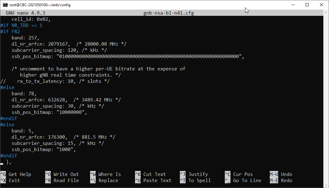
Step 3 : Make a symbolic link from the configuration file to enb.cfg as shown below.
![]()
Step 4 : Check if the symbolic link is properly made
![]()
Troubleshoot
Based on our observation, it seems that most of commercial UEs that claims to support NR NSA works well with Amarisoft Callbox. Most of the difficulties with NSA test that users faces comes from mismatch between UE NR band support and Callbox configuration or failing to meet RRC measurement criteria in terms of configuration or cell power during the test.
I would suggest you to go through each and every items in this section and check all of them one by one if you have any difficulties in getting NSA working
Requirement for UE Capability Information
By default, Amarisoft gNB triggers 'measurement report requestfor NR' and 'NR addition' based on UE Capability Information from UE. Followings are the configuration and the required UE Capability Information.
Requirement for UE Network Capability
Check out Attach Request message and make it sure that the UE support DCNR.
UE network capability:
0xf0 (EEA0=1, 128-EEA1=1, 128-EEA2=1, 128-EEA3=1, EEA4=0, EEA5=0, EEA6=0, EEA7=0)
0x70 (EIA0=0, 128-EIA1=1, 128-EIA2=1, 128-EIA3=1, EIA4=0, EIA5=0, EIA6=0, EIA7=0)
0xc0 (UEA0=1, UEA1=1, UEA2=0, UEA3=0, UEA4=0, UEA5=0, UEA6=0, UEA7=0)
0x40 (UCS2=0, UIA1=1, UIA2=0, UIA3=0, UIA4=0, UIA5=0, UIA6=0, UIA7=0)
0x19 (ProSe-dd=0, ProSe=0, H.245-ASH=0, ACC-CSFB=1, LPP=1, LCS=0, 1xSRVCC=0, NF=1)
0x80 (ePCO=1, HC-CP CIoT=0, ERw/oPDN=0, S1-U data=0, UP CIoT=0, CP CIoT=0, ProSe-relay=0, ProSe-dc=0)
0xb0 (15 bearers=1, SGC=0, N1mode=1,
Requirement for UE Capability Equniry
In order to get the UE capability information for both LTE and NR, you should send UE capability enquiry with both nr and uetra-nr requested as shown below. (
|
message c1: ueCapabilityEnquiry: { rrc-TransactionIdentifier 0, criticalExtensions c1: ueCapabilityEnquiry-r8: { ue-CapabilityRequest { }, nonCriticalExtension { nonCriticalExtension { nonCriticalExtension { nonCriticalExtension { nonCriticalExtension { requestedFreqBandsNR-MRDC-r15 { bandInformationEUTRA: { bandEUTRA 3 }, bandInformationNR: { bandNR 78 } }, nonCriticalExtension { nonCriticalExtension { requestedCapabilityNR-r15 { }, nonCriticalExtension { nonCriticalExtension { rrc-SegAllowed-r16 enabled } |
Requirement for measurement request
If NR-B1 is configured in meas_config_desc, UE Capability Information should carry supportedBandListEN-DC-r15. This IE should contain the NR band you configured in the enb.cfg. Following is an example for this parameter.
|
irat-ParametersNR-r15 { en-DC-r15 supported, { bandNR-r15 1 }, { bandNR-r15 78 } } }, |
Requirement for NR addition
To let gNB to trigger NR addition in RRC, UE Capability Information should carry. This IE should contain the LTE andNR band you configured in the enb.cfg. Following is an example for this parameter. (
|
supportedBandCombinationList { { bandList { eutra: { bandEUTRA 1, ca-BandwidthClassDL-EUTRA a, ca-BandwidthClassUL-EUTRA a }, nr: { bandNR 78, ca-BandwidthClassDL-NR a, ca-BandwidthClassUL-NR a } }, featureSetCombination 0, mrdc-Parameters { dynamicPowerSharingENDC supported, simultaneousRxTxInterBandENDC supported }, powerClass-v1530 pc2 } }, |
Common Issues
These are common issues that you may come across for NSA call setup. Whenever you have any issues even when LTE attach is completed, always check out Requirement for UE Capability Information first and make it sure that all the requirement is met. And then check out the points listed below.
Uninteded Measurement Configuration
: If you see the unintended Measurement Configuration as shown in the left column of the following table, it is highly likely that you have following issues
- UE does not support NSA band combination that you configured in the configuration file. ==> Possible Solution : Change the band combination that are supported by the UE and make it sure that you get all the required UE capability Information as described in Requirement for UE Capability Information section.
|
Uninteded Measurement Configuration |
Intended Measurement Configuration |
|
measObjectToAddModList with only for MGC (LTE Cell). No SCG cell.No reportConfigToAddModList and No measIdToAddModList |
measObjectToAddModList with both MCG(LTE) and SCG(NR) and reportConfigToAddModList and measIdToAddModList |
|
message c1: rrcConnectionReconfiguration: { rrc-TransactionIdentifier 0, criticalExtensions c1: rrcConnectionReconfiguration-r8: { measConfig { measObjectToAddModList { { measObjectId 1, measObject measObjectEUTRA: { carrierFreq 300, allowedMeasBandwidth mbw100, presenceAntennaPort1 TRUE, neighCellConfig '01'B } } }, quantityConfig { quantityConfigEUTRA { } }, measGapConfig release: NULL }, |
message c1: rrcConnectionReconfiguration: { rrc-TransactionIdentifier 0, criticalExtensions c1: rrcConnectionReconfiguration-r8: { measConfig { measObjectToAddModList { { measObjectId 1, measObject measObjectEUTRA: { carrierFreq 300, allowedMeasBandwidth mbw100, presenceAntennaPort1 TRUE, neighCellConfig '01'B } }, { measObjectId 2, measObject measObjectNR-r15: { carrierFreq-r15 632256, rs-ConfigSSB-r15 { measTimingConfig-r15 { periodicityAndOffset-r15 sf20-r15: 0, ssb-Duration-r15 sf1 }, subcarrierSpacingSSB-r15 kHz30 }, quantityConfigSet-r15 1, bandNR-r15 setup: 78 } } }, reportConfigToAddModList { { reportConfigId 1, reportConfig reportConfigInterRAT: { triggerType event: { eventId eventB1-NR-r15: { b1-ThresholdNR-r15 nr-RSRP-r15: 56, reportOnLeave-r15 FALSE }, hysteresis 0, timeToTrigger ms100 }, maxReportCells 8, reportInterval ms120, reportAmount r1, reportQuantityCellNR-r15 { ss-rsrp TRUE, ss-rsrq TRUE, ss-sinr TRUE } } } }, measIdToAddModList { { measId 1, measObjectId 2, reportConfigId 1 } }, quantityConfig { quantityConfigEUTRA { filterCoefficientRSRP fc3 }, quantityConfigNRList-r15 { { measQuantityCellNR-r15 { filterCoeff-RSRP-r15 fc3 } } } }, measGapConfig setup: { gapOffset gp0: 16 } }, |
Uninteded Measurement Event Configuration
: If you are trying to do measurement based NSA (i.e, NR Addition only after the expected measurement report) or various types of cell changes after NSA setup, you need to carefully check on the logics of measurement Event application. Even if various events are explicitely configured in meas_config_desc, whether they are applied to RRC Connection Reconfiguration or not is determined by various factors. Read carefully on the description of meas_config_descforLTE and meas_config_desc for NR in enb document for the details. For ENDC case, the logic would become even more complicated. So it is strongly suggested to read the entire section carefully before you start testing.
No Measurement Report
: If you don't have any measurement report even when you have no problem with UE capability Information and Intended Measurement Configuration as described above, I would recommend you to check followings
- Check if all the necessary antenna (or cable) is connected to sdr for NR (sdr 1 - the second sdr card by default).
- Check tx_gain and if the gain is is property set for your test setup. (Refer to this note to check and change tx_gain)
- Make it sure that cell_gain is set to 0 (the default value) for every cell. (Refer to this note to check the current cell gain for each of the cells)
- (If there is no problem with items listed above), check on UE log (or any display) to see if UE detects any power on NR cell (you may need to get access to UE log or any monitoring App for your DUT for this).
SCG Failure
: You may have some problem even after everything mentioned above went OK. One of the most common failure would be to get SCG Failure Information. SCG Failure happens in various stages and mode, UE send SCGFailureInformation with a specific cause. So the thing you need to do at this stage is to check out the cause specified in SCGFailureInformation and handle the problem accordingly. Check out this note for the description of each cause of SCG failure.