SDR - Multi Cells on One SDR
The purpose of this tutorial is to show you how to configure (map) multiple cells to single sdr card. This kind of mapping is possible as long as following condition is met.
- The center frequency of every cell should be within the frequency and bandwidth range of each sdr card support. (Both SDR50 and SDR100 support upto 6 Ghz frequency in terms of center frequency)
- The bandwidth aggregation of all cells should be accommodated by the each sdr card(SDR50 support upto 50 Mhz and SDR100 support upto 100 Mhz in terms of bandwidth)
- In case of FDD, both Uplink and Downlink frequency and Bandwidth of all cells should be accommodated by each SDR card
However, you should take into considerations a few possible limitations as below. This tutorial will be updated as we confirm further on following items. So for now, I would not recommend you to try any of the following cases.
- This feature is supported only on Callbox and is not supported on UEsim
- LTE + NR mapping on the same sdr card is still under test. Theoretically this should be possible, but some tricky issues were identified during the test.
- It is not easy to find LTE and NR that can map onto single sdr card due to the limited bandwidth supported by sdr card. The frequency separation between LTE and NR should be less than 50 Mhz (SDR50) or 100 Mhz(SDR 100)
- For LTE TDD + NR TDD, it is not confirmed whether we can use different DL and UL configuration for each cell
- It is not confirmed whether LTE FDD and NR TDD can be mapped onto the same sdr card.
- It is not confirmed whether different subcarrier spacing between LTE and NR can be used.
Table of Contents
- SDR - Multi Cells on One SDR
Introduction
Configuring multiple wireless communication cells to operate simultaneously on a single software-defined radio (SDR) card is a sophisticated capability that enables efficient use of radio hardware in advanced test and development environments. SDR technology abstracts traditional radio components into software, allowing flexible configuration of frequency, bandwidth, and protocol parameters. In the context of cellular network testing—such as LTE, NR (5G), and various radio access technologies—SDR cards like the SDR50 and SDR100 provide high-frequency coverage (up to 6 GHz) and sizable bandwidth aggregation (up to 50 MHz or 100 MHz, respectively). By mapping multiple cells onto a single SDR card, users can simulate complex network topologies, conduct multi-cell functionality tests, and optimize hardware utilization. The architectural approach relies on the SDR card’s ability to synthesize and process signals for several cells within its hardware limits, requiring careful coordination of center frequencies, cumulative bandwidth, duplexing modes (FDD/TDD), and protocol compatibility. This capability holds particular significance in laboratory testbeds, callbox environments, and automated validation systems, where density, flexibility, and cost-effectiveness are critical. However, the technique also introduces challenges, such as spectrum overlap, bandwidth constraints, and protocol interoperability, especially when mixing technologies like LTE and NR. Understanding these trade-offs and the operational boundaries of SDR hardware is essential for implementing robust and reliable multi-cell mapping solutions in wireless network testing and research.
-
Context and Technology Overview
- SDR (Software-Defined Radio) cards offer reconfigurable radio platforms capable of supporting various cellular standards, including LTE and NR (5G).
- Mapping multiple cells onto a single SDR card leverages the card’s ability to handle multiple signal chains within its supported frequency and bandwidth envelope.
- This approach is typically employed in controlled environments, such as callboxes or network simulators, to maximize test coverage and hardware efficiency.
-
Relevance and Importance of the Tutorial Topic
- Enables users to perform multi-cell testing scenarios without requiring dedicated SDR hardware for each cell, reducing cost and complexity.
- Supports advanced test setups, such as carrier aggregation, interworking between LTE and NR, and dual connectivity scenarios.
- Helps researchers and engineers evaluate device and network behavior under realistic multi-cell configurations.
-
Expected Learning Outcomes
- Understand the technical prerequisites and limitations for mapping multiple cells to a single SDR card.
- Gain practical knowledge on configuring cell parameters—such as frequency, bandwidth, and duplexing—to fit within SDR hardware constraints.
- Acquire awareness of known restrictions and experimental aspects, including technology interworking and protocol compatibility.
-
Prerequisite Knowledge and Skills
- Familiarity with cellular network architecture, including concepts like cells, frequency bands, and duplexing methods (FDD/TDD).
- Basic understanding of SDR principles and experience with SDR-based test platforms (e.g., Callbox systems).
- Awareness of LTE and NR technical parameters, such as bandwidth allocation, center frequency, and subcarrier spacing.
- General knowledge of test automation and network simulation environments is recommended for advanced configurations.
Summary of the Tutorial
This tutorial describes a low-layer test procedure for configuring and verifying a multi-cell setup using Amarisoft Callbox and UEsim with SDR (Software Defined Radio) cards, focusing on the case of two LTE cells and one NR cell.
-
Test Environment and Setup:
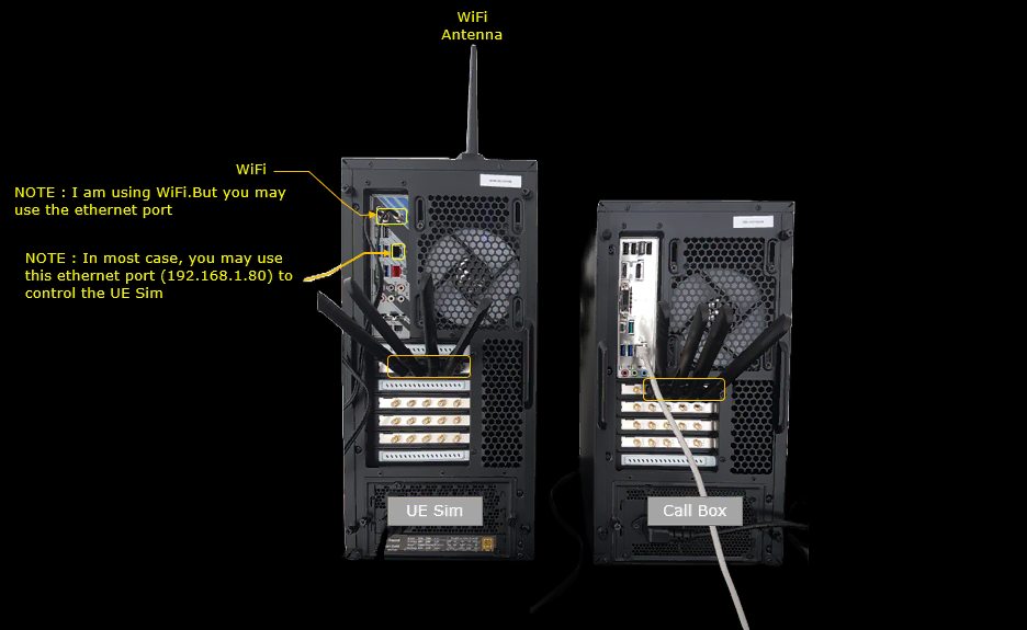
- The test utilizes Amarisoft Callbox and UEsim with at least two SDR cards. In real test setups, two SDR cards are connected with antennas on both Callbox and UEsim.
- SIM cards provided with the system are used, and no complex IP layer configuration is required for these low-layer tests.
-
Key Configuration Parameters:
- For Callbox (enb): rf_driver, rf_ports, Basic Cell Parameters, rf_port
- For UEsim: cell group configuration, cell_index
-
Test Procedure: 2 LTE on One SDR (Test 1)
- Three cells are configured on the Callbox: two LTE cells and one NR cell.
- The two LTE cells are mapped to the same SDR card, while the NR cell is mapped to another SDR card.
- With commercial phones, each phone can be used to connect to a different cell, or one phone can attempt to connect to each cell sequentially.
- With UEsim, three virtual UEs are configured, each mapped to a different cell. Each cell in the cell_groups is mapped to a different rf_port due to UEsim's lack of support for multicell mapping on a single SDR card. Each UE is assigned a different cell_index to ensure unique cell camping.
-
Configuration Steps:
- The Callbox configuration (enb-multicell-onesdr.cfg) is based on a template and modified to support two LTE FDD and one NR TDD cell.
- LTE bandwidth is set to 10 MHz, NR bandwidth to 40 MHz, and both LTE and NR use 2x2 MIMO.
- Two SDR devices are used on the Callbox: dev0 mapped to sdr0 (LTE), dev1 mapped to sdr1 (NR).
- Two RF ports are configured, with both LTE cells mapped to rf_port 0 and the NR cell to rf_port 1.
- For UEsim (ue-3ue-3sdr.cfg), three SDR cards are used (one per virtual UE), with each cell mapped to a separate rf_port and each UE mapped to a different cell using cell_index (0, 1, 2).
-
Execution Steps:
- Verify that all three cells are active and configured as intended using Callbox commands (cell phy, cell, rf_info).
- On UEsim, check that all three cells are detected and appear active before powering on.
- Power on all UEs and confirm that each UE connects to its assigned cell.
- Verify on the Callbox that all cell IDs appear in the connected list and that each UE is attached and assigned an IP address.
- Confirm UE registration status on the UEsim side as well.
-
Log Analysis:
- Check logs to confirm expected signaling (RRC and NAS) for initial attach procedures.
- Verify correct mapping by correlating cell and UE IDs in the log output.
Important Notes:
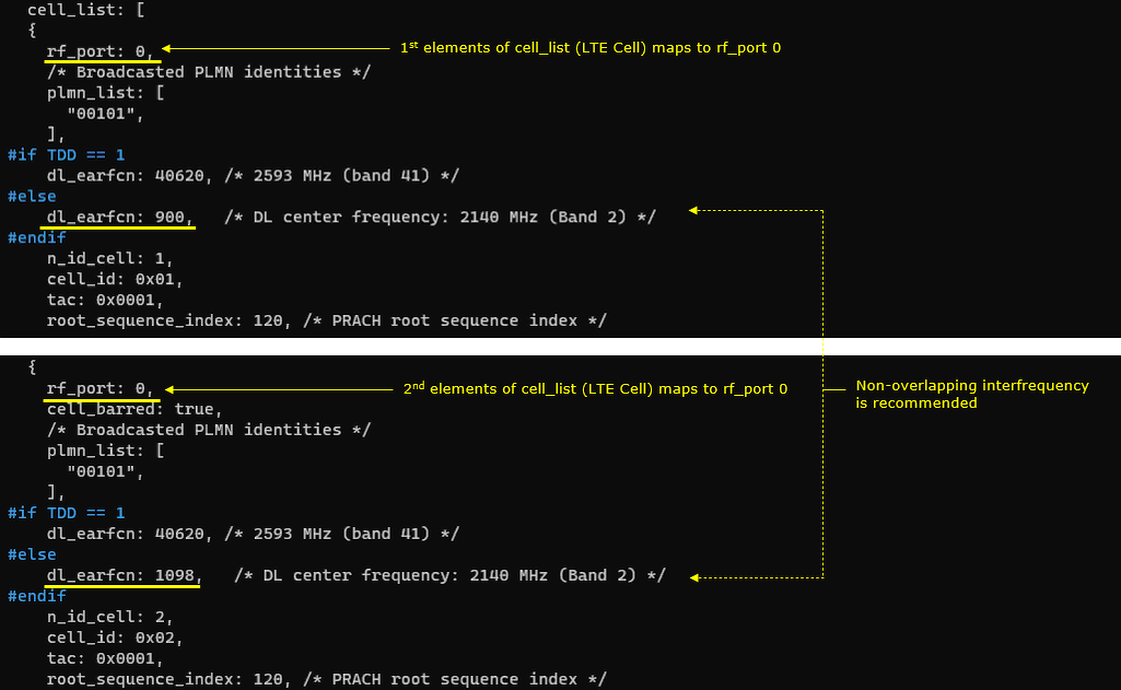
- For frequency planning, it is strongly recommended to use non-overlapping frequencies for the two LTE cells even though the Callbox software does not enforce it.
- UEsim requires each cell to be mapped to a separate SDR due to lack of multicell-on-one-card support.
Test Setup
Test setup for this tutorial is as shown below. This is just for low layer testing, you may not need any complicated IP layer setup.
- SIM Card used in this tutorial is the one delivered with the system as it is.
- If you want to change the configuration, The tutorial Configuration Guide would help
Key Configuration Parameters
Followings are important configuration parameters for this tutorial. You may click on the items for the descriptions from Amarisoft documents.
Test 1 : 2 LTE on One SDR
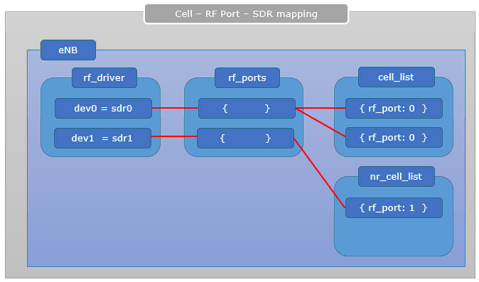
In this test, three cells are configured on Callbox which is LTE + LTE + NR. The two LTE cells are mapped to the same sdr card and the NR cell is mapped to another sdr card. Overall structure of the setting is illustrated as below.
If you are using commercial phones for the test, this is all. You can use one UE trying to connect to each of the cell at a time. or you may use three different UEs and let each of them to get access to each of the cell.
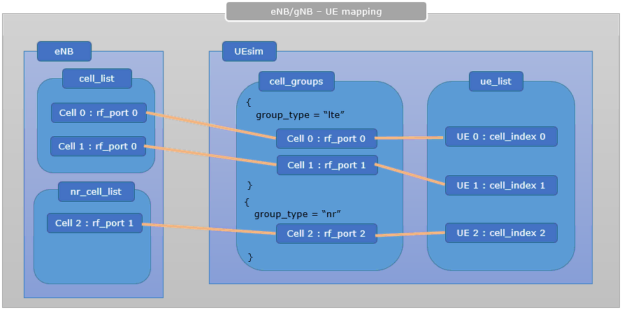
In my case, I used Amarisoft UEsim and configured the three UEs in it and configured as shown below. You would notice two things as below
- Each of the cells in cell_groups is mapped to different rf_port meaning that they are mapped to different sdr. This is because UEsim does not support multicell mapping on a single sdr card as mentioned before.
- I set different values for cell_index for each UEs in ue_list. This makes each UE to camp onto different cells.
Configuration
The configuration shown here is common configuration for all the subtests belonging to Test 1 and I will not show this configuration repeatedly for every subtest.
I have used enb-multicell-onesdr.cfg which is copied and modified from gnb-nsacfg

I am using the default mme, ims config as shown below.

I have used ue-3ue-3sdr.cfg which is copied and modified from ue-nr-nsa.cfg

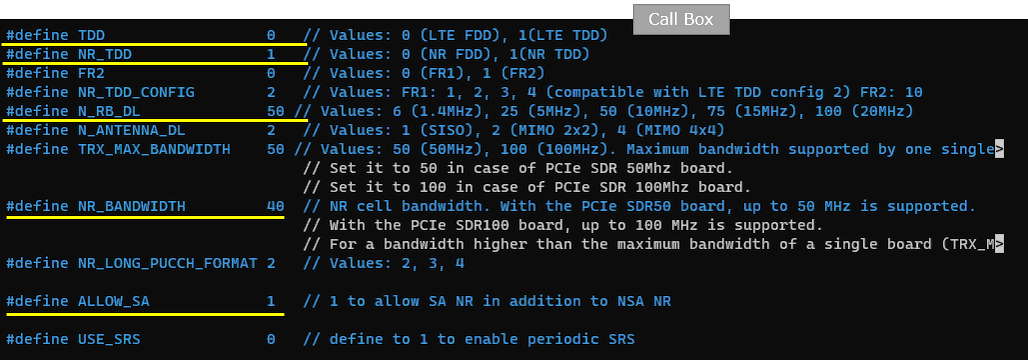
In enb-multicell-onesdr.cfg, it is configured as follows. In this test, two LTE FDD and one NR TDD are used. So TDD is set to 0 (meaning FDD) and NR_TDD is set to 1 (meaning TDD). LTE bandwidth is set to 10Mhz (N_RB_DL 50) and NR bandwidth is set to 40 Mhz (NR_BANDWIDTH 40). And both LTE and NR are set to 2x2 MIMO (N_ANTENNA_DL 2)
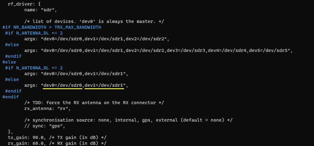
Two SDR cards are used in this test. dev0 is mapped to sdr0 and dev1 is mapped to sdr1.
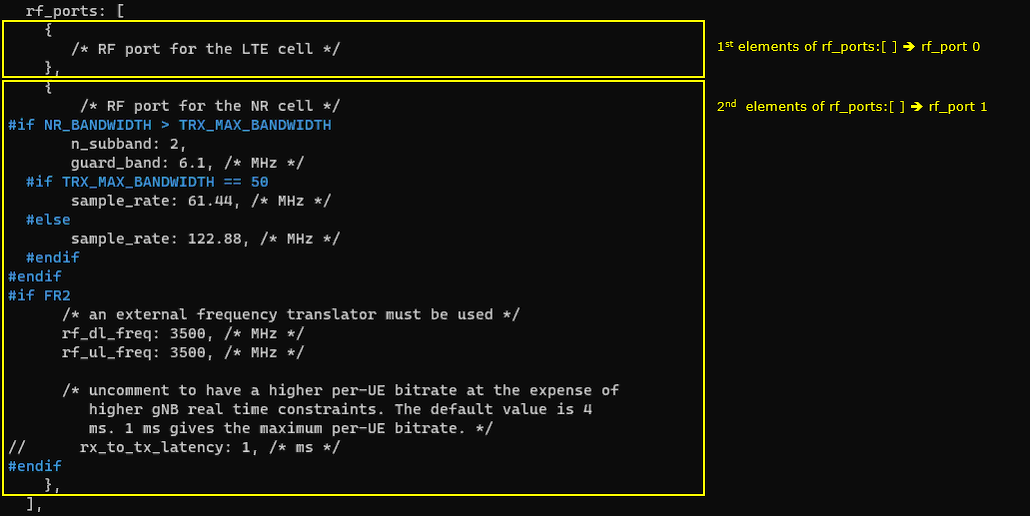
Two RF ports are configured. rf_port0 will be used for LTE cell and rf_port1 will be used for NR. Both RF is set to default configuration without any change.
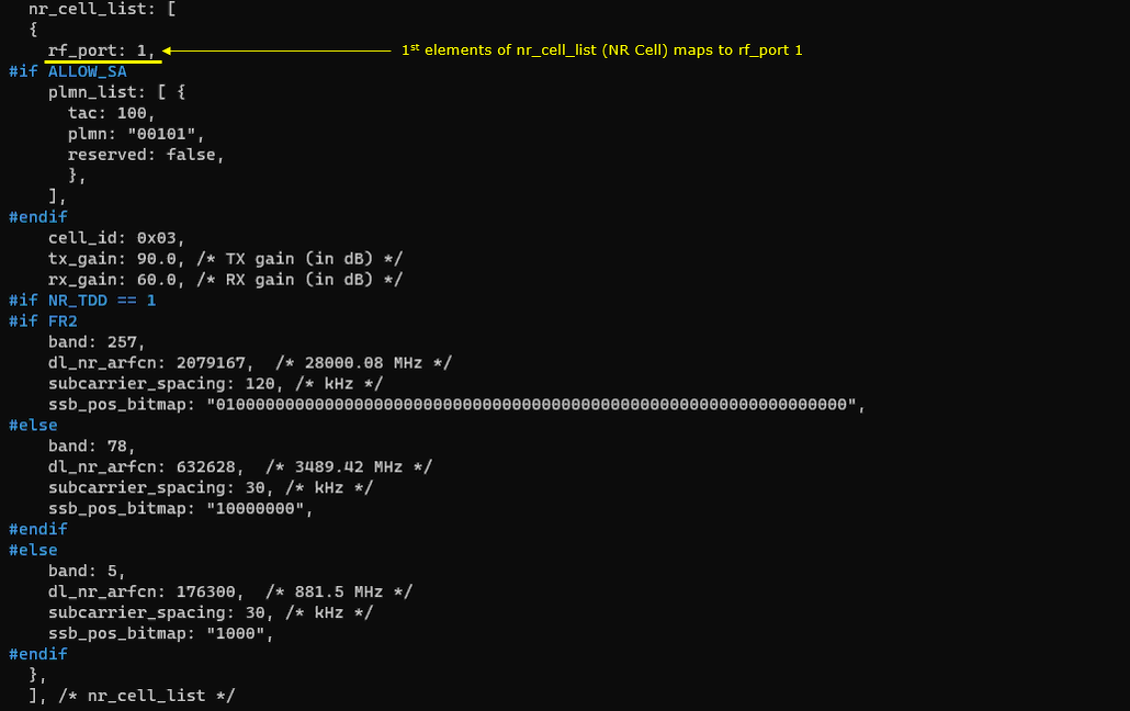
Note that both the first cell and the second cell are mapped to the same rf port(the first rf port (rf_port: 0)).
In nr_cell_list configuration (NR cell configuration), the NR cell is mapped to the second rf port(rf_port: 1).
In ue-3ue-3sdr.cfg, it is configured as follows. This test uses 3 cells (2 LTE cell and 1 NR cell), so N_CELL is set to 3.

UEsim does not support the multicell on one card, so we need 3 sdr card for the test. In this test, dev0 is mapped to sdr0, dev1 is mapped to sdr1 and dev2 is mapped to sdr2.

In cell configuration, you see each of the three cells are mapped to different rf ports. The first LTE cell is mapped to the first rf port(rf_port: 0), the second LTE cell is mapped to the second rf port(rf_portL 1) and the NR cell is mapped to the third rf port(rf_port: 2).
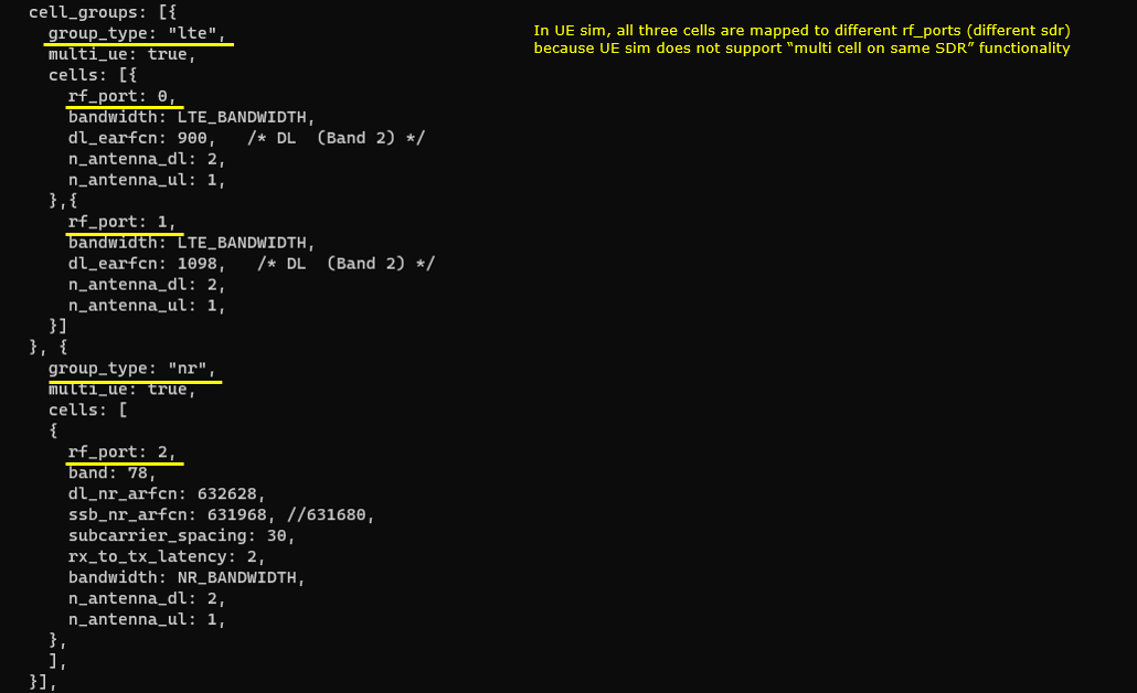
Now we will map each of the 3 UEs to each of 3 cells.
The first UE is mapped to the first cell (cell_index: 0)

The second UE is mapped to the second cell (cell_index: 1)

The third UE is mapped to the third cell (cell_index: 2)

Perform the Test
Check if all three cells show up and their configuration is as you want. You can check the basic configuration with 'cell phy' and 'cell' command, but you cannot check on sdr and rf port mapping with command line command. You may get some additional information with rf_info command, but this one does not show the detailed mapping either.


If you are using UEsim for test, check on UEsim and see if all cells are active and detected all three cells. The UEsim should detect all the cells even before you do 'power_on'.

Check on cell information on UEsim and see if it matches as you intended. Here you see all three cells (2 LTE cells and one NR cell) are detected.

Now power_on all the UEs (power_on *)
![]()
On Callbox, check if all the cells got connected. Make it sure that you see all cell IDs in CL column.
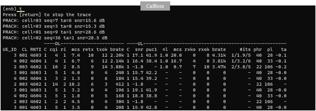
You can check if all the UE got connected and assigned with IP addresses. You should see all three UEs are attached and assigned with IP address.

You can confirm on UEside as well and see if all UEs are properly registered.

Log Analysis
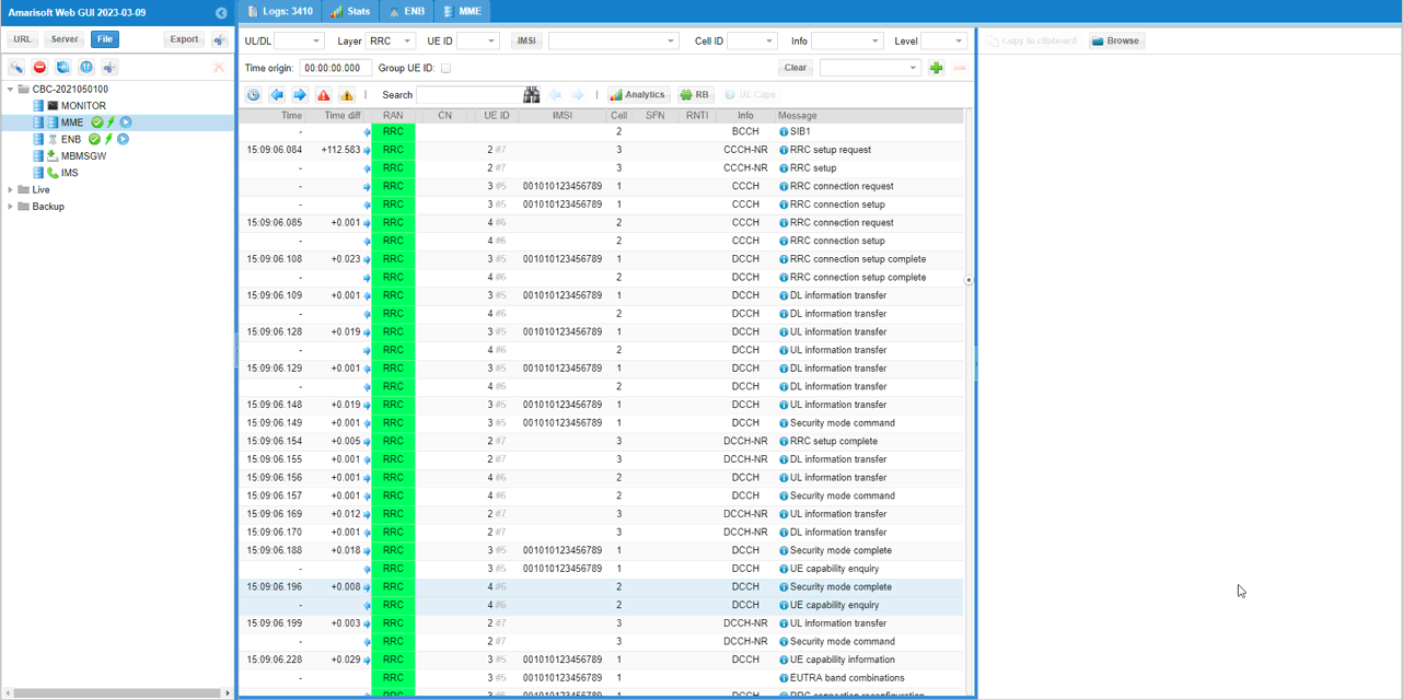
Nothing much you need to check on the log. Just make it sure that you see all RRC (or RRC + NAS) that you need to see for initial attach. You can confirm on this with 'Cell' colum and 'UE ID' column.
