Out of the Box Test - LTE Connection
The purpose of this tutorial is to show you how to do basic connectivity test between a UE and Amari Callbox. It is assumed that you don't have any previous experience with Amari callbox. If you just a new box delivered to you or if you are completely new to the callbox operation, this tutorial would be the good place to start.
The configuration being used in this tutorial is LTE band 7. I think most of the commerical UEs that you can purchase from almost any shops would support LTE band 7 by default. So if you placed Amarisoft default USIM in the phone, I expect it to camp on the the callbox (eNB) without any problem.
As mentioned above, most of the commercial UE would support band 7, but I am not 100% sure if they support all the possible LTE bandwidth. As far as I personally experienced, most of the commercial UE would support all the bandwidth, but some UE may have some bandwidth restrictions (for example, some UE has difficulties with 1.4 Mhz BW). If your UE has any limitation about LTE bandwidth, you can change it by setting N_RB_DL parameter in the configuration file.
|
#define TDD 0 // Values: 0 (FDD), 1(TDD) #define N_RB_DL 25 // Values: 6 (1.4 MHz), 15 (3MHz), 25 (5MHz), 50 (10MHz), 75 (15MHz), 100 (20MHz) #define N_ANTENNA_DL 1 // Values: 1 (SISO), 2 (MIMO 2x2) #define N_ANTENNA_UL 1 // Values: 1, 2 #define CHANNEL_SIM 0 // Values: 0 (channel simulator disabled), 1 (channel simulator enabled) #define NG_ENB 0 // 1 for ng-eNB |
Following is the topics to be covered in this tutorial. Basically Amarisoft Callbox operation is just repetition of the process explained in this tutorial. So if you are new to Amarisoft Callbox, try to repeat this process several times until your finger get used to the process and your mind gets enough confidence with the operation.
Table of Contents
- Out of the Box Test - LTE Connection
Introduction
The Amari Callbox is a versatile and powerful software-defined radio (SDR) test platform designed for simulating and validating cellular network connectivity between User Equipment (UE) and the network infrastructure in a controlled lab environment. It supports a wide range of radio access technologies, including LTE, NR (5G), and legacy networks, making it an essential tool for device manufacturers, network operators, and research institutions. Architecturally, the Amari Callbox integrates a software-based eNodeB (for LTE) or gNodeB (for 5G), a core network emulator, and an RF front-end, enabling comprehensive end-to-end testing without requiring a live commercial network. The system's flexible configuration allows users to define operating bands, bandwidths, antenna settings, and radio parameters, ensuring compatibility with a broad spectrum of commercial UEs and test scenarios. Its significance lies in accelerating device bring-up, regression testing, and protocol verification by providing a repeatable, isolated, and configurable environment. Within the broader telecommunications ecosystem, the Amari Callbox plays a crucial role in ensuring device interoperability, optimizing network features, and expediting certification processes by emulating realistic network conditions and facilitating detailed connectivity analysis. This tutorial focuses on establishing a basic LTE connectivity test using band 7, providing foundational knowledge and practical steps that form the basis for more advanced use cases.
-
Context and Overview
- The Amari Callbox is used to emulate LTE networks, enabling controlled interaction and connectivity testing between a UE and a simulated eNodeB.
- Leveraging software-defined radio technology, it abstracts traditional hardware limitations and allows fine-grained control over network parameters and test conditions.
- The tutorial utilizes LTE band 7, a widely supported frequency band on commercial UEs, ensuring broad device compatibility for entry-level testing.
-
Relevance and Importance
- Understanding the basic connectivity workflow between UE and Amari Callbox is fundamental for anyone beginning work with cellular device validation, network feature development, or protocol analysis.
- The skills acquired in this tutorial serve as a foundation for more advanced testing scenarios, including protocol conformance, performance benchmarking, and custom network feature evaluations.
- Mastery of these procedures reduces device bring-up time, accelerates troubleshooting, and builds confidence in handling SDR-based network simulators.
-
Learning Outcomes
- Gain practical experience in configuring Amari Callbox parameters for LTE connectivity, including frequency band, bandwidth, and antenna settings.
- Develop familiarity with the process required to establish and verify network attachment between a commercial UE and the callbox.
- Understand the impact of configuration variables such as N_RB_DL (number of resource blocks for downlink) and their relationship to device compatibility.
- Acquire troubleshooting techniques for common connectivity issues rooted in band and bandwidth support.
-
Prerequisite Knowledge
- Basic understanding of cellular network concepts (e.g., UE, eNodeB, LTE bands and bandwidths).
- Familiarity with general computing and device configuration procedures.
- No prior experience with Amari Callbox is assumed; the tutorial is suitable for complete beginners.
Summary of the Tutorial
This tutorial describes the Out-of-the-Box LTE Attach and Initial Registration test procedure using the Amarisoft Callbox with default configuration and SIM card. The summary below outlines the step-by-step methodology, including test setup, configuration, execution, and log analysis. Formatting and indentation matches the original content for clarity.
- Test Setup:
- Use the default configuration file (cfg) without modifications.
- Utilize the SIM card delivered with the system as is.
- If configuration changes are necessary, refer to the related Configuration Guide.
- Configuration Steps:
- Navigate to /root/enb/config and ensure enb.cfg is linked to enb.default.cfg (default for Amarisoft Callbox).
- Check /root/mme/config for correct ims.cfg and mme.cfg symbolic links. If not properly linked, use the suggested commands to create the links.
- Check if LTE Service is Running:
- Verify that the LTE service (call box program) is running using # service lte status.
- If required, restart the service using # service lte restart.
- Test Execution Procedure:
- Enter screen mode using screen -r to access the network components installed on the callbox (MME, ENB, IMS, MBMSGW).
- Switch between component command line windows using Ctrl+A and the corresponding number shown before each component.
- Check RF information in the [ENB] window for parameters such as sample_rate, dl_freq, ul_freq, band, dl_ant, ul_ant.
- Optionally, verify basic cell configuration using cell phy and cell commands to confirm frequency band, ARFCN, bandwidth, number of antennas, etc.
- Start log display with the t command. It is recommended to run this before powering on the UE to capture the full attach sequence.
- Power on the UE (for smartphones, disable Airplane mode; for AT command UEs, use AT+CFUN=1).
- Observe PRACH traces and the initial attach sequence in the log output. Successful PRACH and RACH completion strongly indicate a successful attach process.
- Press any key to stop trace and return to the prompt.
- Switch to the (mme) window and run the ue command to check if the UE has been assigned an IP address. Confirm the IP allocation as configured in mme.cfg.
- Log Analysis:
- Log files are saved by default in the /tmp directory (enb0.log for LTE tests). On stopping the test, logs are moved to /var/log/lte.
- Open logs in a text editor to review high-level information and signaling messages (recommended for new users before transitioning to the WebGUI for analysis).
- Analyze key signaling events in the log, such as:
- RRC Connection Request and Setup (indicates UE cell search and PRACH success).
- RRC Connection Setup Complete (confirms completion of RRC setup).
- Authentication (check for Authentication Response and possible failures due to SIM parameter mismatches).
- NAS Security and RRC Security completion (look for Security mode complete messages).
- RRC Connection Reconfiguration initiation and confirmation.
- Attach Accept from the core network (indicates successful registration).
- Default EPS bearer setup and confirmation of UE IP and DNS assignment.
- Completion of Attach process and IP allocation (Attach Complete message).
- User data flow and final RRC Release when traffic ceases.
- General Notes:
- The main focus is on confirming the correct sequence of attach and registration events, as well as IP allocation and bearer setup for the UE.
- For troubleshooting, ensure APN settings on the UE match those configured in the core network.
- Additional log analysis can be performed using the WebGUI for more detailed inspection.
This summary captures the high-level procedures and recommended steps for Out-of-the-Box LTE attach and registration testing, including pre-test setup, execution, and post-test analysis, while preserving the original structure and formatting of the tutorial.
Test Setup
Test setup for this tutorial is as shown below.
- Since this test is for Out of the box testing, I used the default configuration(cfg) file without changing anything in it
- SIM Card used in this tutorial is the one delivered with the system as it is.
- If you want to change the configuration, The tutorial Configuration Guide would help

Configuration
In Amarisoft Callbox, the eNB configuration file is typically referenced by the name enb.cfg. Instead of directly editing this file, Amarisoft usually provides a default configuration file named enb.default.cfg. The command shown here creates a symbolic link so that enb.cfg points to enb.default.cfg. This means the system will use the default configuration file whenever the eNB software loads enb.cfg during startup.
The command ln -sf enb.default.cfg enb.cfg forces the creation of the symbolic link and overwrites the existing link if it already exists. This ensures that enb.cfg always points to the correct default configuration file. Using a symbolic link provides flexibility because the active configuration can be changed simply by redirecting the link to another configuration file without modifying the software or scripts that expect the filename enb.cfg.
In most fresh installations of Amarisoft Callbox, this link is already configured by default. Therefore, running this command is usually not required. However, executing it again does not cause any problem and simply guarantees that the configuration file reference is correctly set. This step is often included in tutorials or setup procedures to ensure a consistent starting configuration before testing or modifying the system.
Go to the directory /root/enb/config and make a symbolic link as follows. (
![]()
Now you should see the enb.cfg file linked to enb.default.cfg as follows. (

In this step you move to the directory /root/mme/config where the configuration files for the Amarisoft MME are stored. The command ll is used to list all the configuration files in this directory so that you can verify how the MME and IMS configuration files are organized.
From the output you can see that several configuration files exist, including ims.default.cfg, mme.default.cfg, mme-ims.cfg and other related configuration files used by the LTE core components. Two important symbolic links are also shown. The file ims.cfg is a symbolic link pointing to ims.default.cfg, and the file mme.cfg is a symbolic link pointing to mme-ims.cfg. This indicates which configuration files are currently active when the MME service starts.
The MME software always loads the configuration file named mme.cfg. Instead of directly editing this file, Amarisoft uses symbolic links so that mme.cfg can point to different configuration profiles depending on the deployment scenario. In this example mme.cfg points to mme-ims.cfg, which means the system is configured to run with IMS related features enabled.
The same concept applies to ims.cfg. The software expects a configuration file named ims.cfg, but the actual configuration is stored in ims.default.cfg. The symbolic link simply connects the expected filename with the real configuration file.
This structure makes configuration management easier because different configuration variants can exist in the same directory. The active configuration can be switched simply by changing the symbolic link target without modifying the program or renaming the configuration files.
Now go to the directory /root/mme/config. You should see the configuration files as below. (

If ims.cfg and mme.cfg is not linked to the files as shown above, you may run following commands to make proper link.
This step ensures that the correct configuration files are used by the MME and IMS components of the Amarisoft Callbox. The software expects the configuration files to be named mme.cfg and ims.cfg when it starts. However, the actual configuration profiles are stored in files such as mme-ims.cfg and ims.default.cfg. To connect these expected filenames with the actual configuration files, symbolic links are created.
The first command creates a symbolic link so that mme.cfg points to mme-ims.cfg. This means the MME service will load the configuration defined in mme-ims.cfg when it reads mme.cfg during startup. This configuration typically includes settings required for LTE core operation with IMS support.
The second command creates a symbolic link so that ims.cfg points to ims.default.cfg. This ensures that the IMS service uses the default IMS configuration file when the system starts.
The option -sf in the ln command forces the symbolic link creation and replaces the existing link if it already exists. This guarantees that the links are always updated to the correct target files. Running these commands does not modify the actual configuration files. It only ensures that the expected filenames used by the system point to the proper configuration profiles.
![]()
Check if LTE service is Running
Before performing any LTE testing with Amarisoft Callbox, you first need to confirm that the LTE service is running. The LTE service is the main program that launches the eNB, MME, and other related LTE core components required for the system to operate. If this service is not running, the Callbox will not transmit LTE signals and no UE will be able to detect or connect to the network.
The command service lte status is used to check the execution status of the LTE service. Internally this command redirects to systemctl status lte.service, which displays detailed information about the systemd service responsible for running the Amarisoft LTE stack.
From the status output you can verify several important details. The line Active: active (running) indicates that the LTE service is currently running. The Loaded section shows the location of the service definition file, which in this case is /usr/lib/systemd/system/lte.service. The output also displays the main process ID and the list of tasks that belong to this service.
The process tree shows that the LTE service is launched through the script /root/ots/ltestart.sh. This startup script is responsible for initializing the LTE system components and keeping them running under systemd control.
If the service status shows active (running), it confirms that the Amarisoft Callbox software is properly running and ready for LTE testing. If the service is not active, the LTE stack must be started before proceeding with further configuration or UE connection tests.
Whatever you want to test, the first thing you need to do is that call box program (LTE Service) is running. You can check on the execution status of the call box program by running following command and you should get the result as shown below
# service lte status

# service lte restart
Perform the Test
If it is confirmed that the lte service is running, go to screen mode by running 'screen -r' and follow through the steps as shown below. The steps shown here is the procedure that you would use for almost every test and it is highly recommended to get familiar with these steps. For further commands you can use in this screen mode, refer to the tutorial : Command Line Command
Before checking detailed Callbox logs or interacting with the running LTE processes, you first open the screen session using the command screen -r. In Amarisoft environments, the LTE service is often started inside a GNU screen session so that the main console output remains available even after you disconnect from the terminal. Reattaching to this screen session lets you see the live runtime messages from the Callbox software.
The command screen -r means resume attach. It reconnects your terminal to a previously detached screen session. This is useful when the LTE service is already running in the background and you want to return to the same console to monitor logs or interact with the program.
Sometimes other documents use screen -x instead of screen -r. The option screen -x allows simultaneous attachment, which means multiple terminals can connect to the same screen session at the same time. The option screen -r is mainly used to reattach to a detached session. In many practical cases both commands may appear to give a similar result, especially when there is only one existing detached screen session.
So the purpose of this step is to reconnect to the Amarisoft runtime console. Once attached, you can directly observe system messages, monitor status changes, and check whether the Callbox software is behaving as expected during operation.
First open the screen window with the 'screen' command. (

After attaching to the screen session, you will see the console environment where the main network components of the Amarisoft Callbox are running. This screen shows the active modules that make up the LTE network stack running inside the Callbox system. In this example, the installed components include MME, ENB, IMS, and MBMSGW. Each of these modules represents a different functional part of the LTE core and radio access network.
The MME module handles mobility management and control signaling between the UE and the core network. The ENB module controls the LTE radio access node that communicates directly with the UE. The IMS module supports IP Multimedia services such as VoLTE, and the MBMSGW module is responsible for multicast and broadcast services. These modules are launched inside separate windows within the screen session so that each component can run independently while still being monitored from a single terminal.
At the bottom of the screen you will see a list of window numbers associated with each module. These numbers allow you to switch between the command line interfaces of the different components. By pressing Ctrl+A followed by the corresponding number, you can move to the console of a specific module. For example, pressing Ctrl+A and then 1 switches the terminal to the ENB window, while pressing Ctrl+A and then 0 switches to the MME window.
The currently selected module is highlighted in yellow. This indicates which module�s command interface is currently active and receiving keyboard input. This screen-based structure allows the operator to easily monitor logs and interact with each component of the LTE system without opening multiple terminal sessions.
In short, you would see a number before each component name. With Ctrl+A and the number before the component name, you can switch to command line window for the specific component. For example, if you press Ctrl+A+1, the command line window switches to ENB and if you press Ctrl+A+0, the command line window switches to MME and so on.

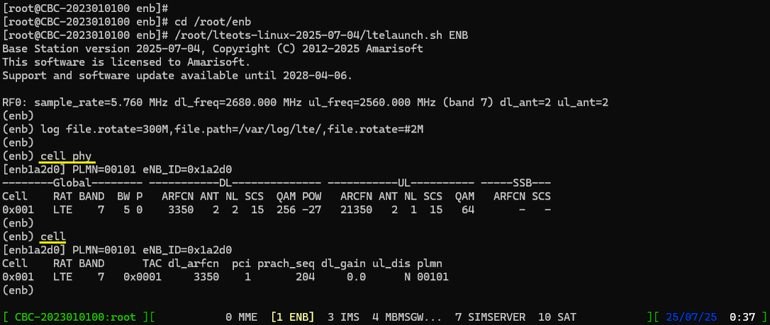
When you switch to the ENB window in the screen session, the system immediately prints several RF related parameters without requiring any additional command. These messages appear during the initialization of the eNB software and provide a quick summary of the current radio configuration used by the Callbox.
The displayed information includes parameters such as sample_rate, dl_freq, ul_freq, band, dl_ant, and ul_ant. These values represent the fundamental RF configuration of the LTE base station. The sample_rate indicates the baseband sampling rate used by the RF processing chain. The dl_freq and ul_freq indicate the downlink and uplink center frequencies configured for the cell. The band value indicates which LTE operating band is being used. The dl_ant and ul_ant parameters indicate the number of downlink and uplink antennas configured for transmission and reception.
This information is useful because it allows you to quickly verify the RF setup before performing any UE testing. By checking these parameters you can confirm whether the Callbox is transmitting on the intended frequency band and whether the antenna configuration matches your test setup.
It is especially important to verify that the LTE band and frequency configured in the eNB match the capabilities of the UE being used for testing. If the UE does not support the configured band, it will not detect the cell and the attach procedure will not start. In such a case you need to modify the enb.cfg configuration file and adjust the band or frequency parameters to match the band supported by your test device. This quick RF summary therefore serves as an important early validation step before proceeding with further LTE testing.

Before starting any UE test, it is strongly recommended to verify the basic cell configuration in the eNB console. Although this step is not strictly required, it helps confirm that the LTE cell is configured as intended and prevents many common test setup issues. This verification can be done using the commands cell phy and cell.
The command cell phy displays the physical layer configuration of the LTE cell. It shows important parameters such as operating band, ARFCN, bandwidth, number of antennas, number of transmission layers, subcarrier spacing, modulation configuration, and transmit power. These values describe how the radio signal is generated and transmitted by the eNB. By reviewing this information, you can confirm that the RF configuration matches the expected test conditions.
The command cell displays the higher level cell configuration used by the network layer. This output typically includes parameters such as PLMN, TAC, PCI, PRACH configuration, downlink gain, and other identifiers that define the LTE cell within the network. These values are important for UE detection and network attachment procedures.
By checking the outputs of cell phy and cell, you can quickly confirm that the LTE band, ARFCN, bandwidth, antenna configuration, and network identifiers are correctly configured. This simple validation step helps ensure that the test environment is properly prepared before attempting UE connection or further LTE testing.
In the ENB console you can start real time log monitoring by running the command t. This command enables trace output so that the system begins displaying internal eNB events and signaling messages directly on the console. Once the trace is enabled, the console continuously prints runtime information generated by the base station software.
This command can be executed at any time during operation. However, it is usually recommended to run the command before powering on the UE. By starting the trace earlier, you can capture the complete sequence of events beginning from the very first stage of UE detection and initial attach. This makes troubleshooting much easier because no early messages are missed.
After the command is executed, the console enters trace mode and begins printing logs as events occur in the system. The message Press [return] to stop the trace indicates that the trace display will continue until the user presses the Enter key. When Enter is pressed, the trace display stops and the console returns to the normal command prompt.
This simple trace mechanism provides a convenient way to observe the signaling behavior of the LTE base station in real time. During UE testing you will typically see messages related to cell detection, random access procedure, RRC signaling, and other LTE protocol activities appearing in this log output.
Run 't' command to start log display.
You can run this command any time during the test, but it is always good idea to run this command before you power on UE to get the log from very beginning of initial attach.

Power on UE (
If the trace command t was started before powering on the UE, the eNB console will capture the very first radio access attempts made by the UE. One of the earliest events that appears in the trace is the PRACH message. PRACH indicates that the UE has transmitted a Random Access preamble to begin the LTE access procedure.
The appearance of a PRACH trace message is an important troubleshooting indicator. It confirms that the eNB is successfully receiving the PRACH preamble transmitted by the UE. This means that the RF link between the UE and the base station is working at a basic level. It also confirms that the UE has detected the LTE cell and started the Random Access procedure.
If PRACH is properly received and the RACH procedure completes successfully, the UE will proceed to the next steps of the connection setup. After the RACH process, the system usually begins to display scheduling and traffic related information in the trace output. When these traffic statistics start appearing, it often indicates that the UE has successfully established a connection with the network.
In the trace output, the line showing PRACH indicates that the random access preamble has been detected by the eNB. Following this, the table-like statistics display various downlink and uplink parameters such as CQI, MCS, SNR, retransmission counters, and throughput information. These values represent the real-time radio link status between the eNB and the UE.
When these statistics start updating continuously, it generally indicates that the LTE connection is active and data transmission is taking place. However, to fully confirm that the UE registration and attach procedure has completed successfully, the detailed signaling logs should be reviewed.
Regarding the details on the meaning of each column of this log and how to use the information for troubleshoot, refer to this tutorial.

Press any key to stop trace and go back to prompt.

After the UE completes the initial attach procedure, the next step is to verify whether an IP address has been assigned to the UE. This check is performed from the MME console. Switch to the MME window in the screen session and run the command ue. This command displays the list of UEs currently registered in the core network along with various information related to their connection status.
The output shows identifiers such as SUPI, IMEISV, temporary identities like M-TMSI or 5G-TMSI, the registration status, and the number of active bearers. One of the most important fields in this output is the IP address column. If the UE attach procedure has been completed successfully, the UE should be assigned at least one IP address.
The assigned IP addresses are taken from the configuration defined in the mme.cfg file. In the configuration, each APN specifies parameters such as pdn_type, address range, and DNS settings. For example, an APN configured for IPv4 will allocate addresses from a defined IPv4 pool, while another APN may allocate both IPv4 and IPv6 addresses. The parameters first_ip_addr and last_ip_addr define the address range used by the core network when assigning IP addresses to connected UEs.
Normally you should see at least the first IP address assigned to the UE. In many cases the UE may receive two addresses, one IPv4 and one IPv6. However, if the IMS APN is not enabled or configured on the UE device, you may only see the IPv4 address. For this tutorial it is sufficient to see the first IP address.
If no IP address appears in the ue output, it usually indicates a problem in the attach or PDN session establishment procedure. A common cause is an APN mismatch between the UE and the core network configuration. The Amarisoft core network typically defines several default APNs such as default, internet, ims, and sos. The APN configured on the UE must match one of the APNs defined in the MME configuration file. If the APN names do not match, the UE may successfully attach to the network but fail to obtain an IP address. Adjusting the APN configuration either on the UE or in the mme.cfg file usually resolves this issue.
Switch to (mme) window and Run the command [ue] in (mme) and it will show whether UE is assigned with any IP and what are those IPs. The IPs assigned to the UE is configured in mme.cfg file as indicated below.

Once the UE successfully receives an IP address and the attach procedure is confirmed, you can leave the screen session while keeping all the network processes running in the background. This is done by detaching from the screen session.
To detach from the screen session, press Ctrl+A first and then press D. These keys should be pressed sequentially, not at the same time. When this command is executed, the current screen session is detached and the terminal returns to the normal shell prompt.
Detaching from the screen session does not stop the LTE service or any of the running network components. The MME, ENB, IMS, and other modules continue running exactly as before. The screen session simply continues in the background while you regain access to the normal terminal.
After detaching, the system displays a message indicating that the screen session has been detached. If you later want to return to the running console, you can reconnect to the same session using the command screen -r. This mechanism allows you to monitor or control the running Callbox processes whenever needed without interrupting the LTE network operation.
In short, you can go out of the screen with [ Alt + A and D] .

Log Analysis
In most case, you may use WebGUI to analyze the log, but in this tutorial I will show you how to check out the log with text editor to give you the idea on where the log is collected and the format of the saved log. I would recommend you to check out the log in this way at least a few times when you just starts to use Amarisoft product and then WebGUI would be more handy tools for log analysis.
By default the log file is saved in /tmp directory (you can change the location of the log file in configuration file, but in most case most user just use the default location which is /tmp). In case of LTE test, you will find the log file named enb0.log in /tmp directory while the test is trunning. (

After detaching from the screen session, you can examine the detailed logs generated by the eNB. These logs are usually stored in files such as /tmp/enb0.log or in the directory specified in the configuration. You can open the log file using any text editor such as nano, vi, or less.
At the beginning of the log file, you will see several lines of high level information about the eNB configuration. This section acts as metadata for the log and provides a quick overview of how the base station was configured when the system started. It includes information such as the software version, compiler version, license information, and general system capabilities.
The log also shows important radio configuration parameters. These include the cell identifier, ARFCN, PCI, duplex mode, bandwidth, cyclic prefix configuration, and other physical layer parameters. Additional sections describe configurations related to PRACH, PUCCH allocation, scheduling resources, and various control channel settings. These parameters define how the LTE cell operates at the physical layer.
This metadata section is useful because it allows you to quickly verify the configuration that was active when the log was generated. If you encounter unexpected behavior during testing, checking this information helps confirm whether the eNB was running with the intended parameters. Reviewing this section of the log is therefore a good first step before analyzing detailed signaling messages further down in the file.
Check out this tutorial to the details on this meta data.

After reviewing the metadata section at the beginning of the log file, the next step is to examine the signaling messages generated during the UE connection procedure. One of the first important messages to check is the RRC Connection Request followed by the RRC Connection Setup.
The RRC Connection Request message is transmitted by the UE after it completes the random access procedure. If this message appears in the log, it indicates that the UE has successfully detected the cell, performed the PRACH procedure, and started the RRC connection establishment process. This message typically contains fields such as the random UE identity and the establishment cause, which describes the reason for the connection request.
After receiving the RRC Connection Request, the eNB responds with the RRC Connection Setup message. This message is sent from the base station to the UE and contains the initial configuration required for establishing the RRC connection. The configuration includes parameters related to signaling radio bearers, RLC configuration, and other radio resource settings needed for further communication.
Seeing both of these messages in the log confirms that the early stages of the LTE connection setup are functioning properly. The UE has completed the random access procedure and the eNB has accepted the connection request and started the RRC setup procedure. If the RRC Connection Request message does not appear in the log, it usually indicates that the random access procedure did not complete successfully, and the troubleshooting should begin with checking the PRACH and RF related configurations.

The next message to check in the log is RRC Connection Setup Complete. This message is transmitted by the UE after it successfully receives and processes the RRC Connection Setup message from the eNB. If this message appears in the log, it indicates that the UE has accepted the configuration sent by the base station and the RRC connection establishment has been completed successfully.
When the eNB receives RRC Connection Setup Complete, it means that the UE has transitioned into the connected state and is ready to proceed with the next stage of the procedure. At this point the UE begins sending NAS signaling messages such as Attach Request through the established RRC connection. This is why NAS messages often appear immediately after the RRC Connection Setup Complete message in the log.
If the UE fails to complete the RRC setup procedure, the connection attempt usually restarts from the random access stage. In such a case the UE typically performs the RACH procedure again and sends another RRC Connection Request. When this happens repeatedly, you may observe multiple RACH attempts followed by repeated RRC Connection Request messages without reaching the RRC Connection Setup Complete stage.
Therefore, confirming the presence of the RRC Connection Setup Complete message is an important step in troubleshooting. It verifies that the UE has successfully completed the RRC connection establishment and that the signaling can proceed to the NAS attach procedure.

After the RRC connection establishment is completed, the network proceeds with the authentication procedure. In this step the core network verifies the identity of the UE using the authentication parameters stored in the SIM or USIM. The authentication process is initiated by the network and the UE must respond with the correct authentication information.
If the authentication process succeeds on the UE side, the UE sends an Authentication Response message. When this message appears in the log, it indicates that the UE has successfully validated the authentication challenge and returned the expected response. This confirms that the SIM authentication parameters are correctly matched between the UE and the core network configuration.
If the log shows an Authentication Failure message instead of Authentication Response, it usually indicates a mismatch in SIM authentication parameters. In most cases this happens when the secret key K or related authentication parameters configured in the core network do not match the parameters stored in the USIM used by the UE.
When this problem occurs, you should verify the SIM authentication configuration in the core network database. In Amarisoft systems these parameters are typically defined in configuration files such as ue_db.cfg or ue_db-ims.cfg. The values defined in these files must match the authentication parameters of the DUT�s USIM. Once the parameters are aligned, the authentication procedure should complete successfully and the UE will proceed to the next stage of the attach process.

After the authentication procedure is completed, the network proceeds with the security setup process. The purpose of this stage is to establish secure communication between the UE and the core network. In LTE there are two layers of security activation. The first layer is NAS security and the second layer is RRC security.
NAS security is established between the UE and the MME. During this stage the network activates integrity protection and encryption for NAS signaling messages. The UE receives a Security Mode Command and responds with Security Mode Complete after successfully applying the security configuration.
When the log shows the message EMM: Security mode complete, it indicates that the UE has accepted the NAS security configuration and that NAS level security has been successfully activated. At this point the signaling messages exchanged between the UE and the core network are protected using the negotiated security algorithms.
After NAS security is established, the system proceeds with the activation of RRC security. RRC security protects the radio control messages exchanged between the UE and the eNB. Together, NAS security and RRC security ensure that both the control plane signaling and the radio link communication are protected against unauthorized access and tampering.

After NAS security has been successfully established, the network proceeds with the second stage of the security procedure, which is the activation of RRC security. RRC security protects the signaling exchanged between the UE and the eNB over the radio interface.
During this step the eNB sends a Security Mode Command to the UE, instructing it to activate the selected ciphering and integrity protection algorithms for the RRC connection. The UE applies the security configuration and then responds with the Security Mode Complete message.
When the log shows the message DCCH: Security mode complete, it indicates that the UE has successfully applied the RRC security configuration and the RRC security procedure has finished. At this point both NAS signaling and RRC signaling are protected, meaning the control plane communication between the UE, eNB, and core network is now operating under the negotiated security context.
After the RRC security procedure is completed, the network usually continues with capability exchange procedures such as UE Capability Enquiry. This allows the eNB to retrieve detailed information about the UE�s supported radio features, including supported LTE bands, MIMO capability, and other radio capabilities needed for further configuration of the connection.

After the authentication and security procedures are completed, the network proceeds with the next stage of the connection establishment process. At this point the eNB initiates the RRC Connection Reconfiguration procedure. This step is used to finalize the radio configuration and prepare the UE for normal communication.
During this procedure the eNB sends an RRC Connection Reconfiguration message to the UE. This message typically includes configuration related to radio bearers, scheduling parameters, and other radio resource settings required for the UE to start data communication. The UE applies the configuration and responds with the message RRC Connection Reconfiguration Complete.
When the log shows RRC connection reconfiguration complete, it indicates that the UE has successfully received and applied the reconfiguration parameters sent by the eNB. This confirms that the radio connection setup is finalized and the communication path between the UE and the network is fully established.
Immediately after this step, the core network signaling also reflects the successful setup of the UE context. For example, messages such as Initial Context Setup Response may appear in the log. These messages indicate that the UE context and associated bearers have been successfully created in the network.
At this stage the LTE attach procedure is essentially completed and the UE is ready for normal data communication. The physical and logical communication paths between the UE, eNB, and core network are now fully established.

After all required RRC and NAS procedures for the initial registration are completed, the network proceeds with the final stage of the LTE attach procedure. At this point the network sends the message EMM: Attach Accept to the UE.
The Attach Accept message indicates that the core network has successfully processed the UE�s Attach Request and that the UE is now officially registered to the LTE network. This message is generated by the MME and delivered to the UE through the eNB. It contains important parameters required for the UE to operate in the network, such as the EPS attach result, tracking area information, and other mobility management parameters.
When this message appears in the log, it confirms that the network has accepted the registration request from the UE. This means that the authentication procedure, security setup, and radio configuration have all been successfully completed. The UE is now considered attached to the network and can begin normal network operations.
Following this step, the UE will usually send an Attach Complete message to acknowledge the successful registration. After this exchange, the default bearer is established and the UE can start using the assigned IP address for data communication. At this stage the initial LTE registration process is fully completed and the UE is ready to exchange user data with the network.

After the initial attach procedure is completed, the network proceeds with the establishment of the default EPS bearer. This step allows the UE to start IP based communication through the LTE network. The bearer setup is initiated by the network through the message Activate default EPS bearer context request.
This message contains several important parameters related to the UE�s data session. One of the most important fields is the PDN address. This field indicates the IP address that has been assigned to the UE. The address is selected from the IP address pool configured in the core network configuration file. In Amarisoft systems, the IP address pool is typically defined in the mme.cfg file.
The message also contains the APN that the UE is connected to. This value indicates the packet data network that the UE requested during the attach procedure. The APN determines which IP address pool and which network configuration will be used for the UE�s data session.
Another important field shown in this message is the DNS server address. The DNS server IP is provided to the UE so that it can resolve domain names when accessing external network resources. In many test configurations, a public DNS server such as 8.8.8.8 is assigned. This value is also configured in the mme.cfg file.
Additional parameters may also appear in this message, such as QoS related information and session bandwidth limits. These values define the quality of service and data rate limitations applied to the UE�s default bearer.
When this message appears in the log, it confirms that the UE has been assigned an IP address and that the default data bearer has been successfully established. At this point the UE is fully attached to the LTE network and ready to exchange IP data with external networks.

After the UE receives the Attach Accept message and the default EPS bearer is activated, the UE sends the Attach Complete message back to the network. This message confirms that the UE has successfully processed the attach acceptance and has accepted the default bearer configuration provided by the network.
When the Attach Complete message appears in the log, it indicates that the UE has finished the attach procedure and the IP session setup is complete. The message usually contains an ESM container that acknowledges the activation of the default EPS bearer context. This confirms that the UE has accepted the assigned IP address and the associated bearer parameters.
Seeing the Attach Complete message is a strong indication that the entire initial attach procedure has been successfully completed. At this stage the UE is fully registered in the LTE network, the security context is established, the default EPS bearer is active, and the UE has a valid IP address assigned.
Once this step is reached, the UE is ready to start normal data communication over the LTE network. Any subsequent signaling or traffic observed in the logs will typically be related to regular user data transmission or network management procedures rather than the initial registration process.

After the initial attach procedure is completed, the UE enters the connected state and user data can start flowing between the UE and the network. During this period the UE and eNB maintain an active RRC connection and the default EPS bearer carries IP traffic such as ping, web access, or application data.
If there is no user data activity for a certain period of time, the network may decide to release the RRC connection in order to conserve radio resources. In LTE this is handled by the eNB through the RRC Connection Release procedure.
When the eNB determines that the connection has been idle long enough, it sends the RRC Connection Release message to the UE. This message instructs the UE to terminate the active RRC connection and transition back to the idle state. Once the UE enters the idle state, it no longer maintains dedicated radio resources but continues to monitor the cell for paging messages.
In the log this event appears as the message RRC connection release. Seeing this message usually indicates that the UE was previously connected and the connection is now being terminated due to inactivity or normal session completion.
This behavior is normal in LTE operation. If the UE later needs to transmit data again, it will reestablish the connection by performing the random access procedure and initiating a new RRC connection establishment process.

RRC / NAS Signaling
: This section is to show you the overall structure of important Rrc messages and Information IE (IE) that are related to this tutorial. It is not intended to describe the details on every RRC/NAS Information elements. With the overall structure and key IEs shown here, it hope it would be easier / clearer to go through the sample log provided in this tutorial or any logs that you captured from your own test setup or live network.
SIB1
: This is the SIB1 message sent by eNB to configure LTE. (
{
message c1: systemInformationBlockType1: {
cellAccessRelatedInfo {
plmn-IdentityList {
{
plmn-Identity {
...
},
cellReservedForOperatorUse notReserved
}
},
trackingAreaCode '0001'H,
cellIdentity '1A2D001'H,
cellBarred notBarred,
intraFreqReselection allowed,
csg-Indication FALSE
},
cellSelectionInfo {
q-RxLevMin -70
},
p-Max 10,
freqBandIndicator 7,
schedulingInfoList {
...
},
si-WindowLength ms40,
systemInfoValueTag 0
}
}
SIB2
: This is the SIB2 message sent by eNB to configure LTE. (
{
message c1: systemInformation: {
criticalExtensions systemInformation-r8: {
sib-TypeAndInfo {
sib2: {
radioResourceConfigCommon {
rach-ConfigCommon {
...
},
bcch-Config {
...
},
pcch-Config {
...
},
prach-Config {
...
},
pdsch-ConfigCommon {
...
},
pusch-ConfigCommon {
...
},
pucch-ConfigCommon {
...
},
soundingRS-UL-ConfigCommon setup: {
...
},
uplinkPowerControlCommon {
...
},
ul-CyclicPrefixLength len1,
pusch-ConfigCommon-v1270 {
...
}
},
ue-TimersAndConstants {
...
},
freqInfo {
...
},
...
},
RrcConnectionSetup
: This is the RrcConnectionSetup message sent by eNB (
{
message c1: rrcConnectionSetup: {
rrc-TransactionIdentifier 0,
criticalExtensions c1: rrcConnectionSetup-r8: {
radioResourceConfigDedicated {
srb-ToAddModList {
...
},
mac-MainConfig explicitValue: {
...
},
physicalConfigDedicated {
pdsch-ConfigDedicated {
...
},
pucch-ConfigDedicated {
...
},
pusch-ConfigDedicated {
...
},
uplinkPowerControlDedicated {
...
},
cqi-ReportConfig {
...
},
soundingRS-UL-ConfigDedicated setup: {
...
},
schedulingRequestConfig setup: {
...
}
AttachRequest
: This is the AttachRequest message sent by UE (
Protocol discriminator = 0x7 (EPS Mobility Management)
Security header = 0x1 (Integrity protected)
Auth code = 0x410496cc
Sequence number = 0x09
Protocol discriminator = 0x7 (EPS Mobility Management)
Security header = 0x0 (Plain NAS message, not security protected)
Message type = 0x41 (Attach request)
EPS attach type = 2 (combined EPS/IMSI attach)
NAS key set identifier:
...
Old GUTI or IMSI:
...
UE network capability:
...
ESM message container:
...
Last visited registered TAI:
...
DRX parameter:
...
MS network capability:
...
Old location area identification:
...
Mobile station classmark 2:
...
Mobile station classmark 3:
...
Supported codecs:
...
Voice domain preference and UE's usage setting = 0x07 (IMS PS voice preferred, CS Voice as secondary, Data centric)
Old GUTI type = 0
MS network feature support = 0x01 (MS supports the extended periodic timer in this domain)
UE additional security capability:
...
AttachAccept
: This is the AttachAccept message sent by Core Network (
Protocol discriminator = 0x7 (EPS Mobility Management)
Security header = 0x2 (Integrity protected and ciphered)
Auth code = 0x6bb083ed
Sequence number = 0x02
Protocol discriminator = 0x7 (EPS Mobility Management)
Security header = 0x0 (Plain NAS message, not security protected)
Message type = 0x42 (Attach accept)
EPS attach result = 2 (combined EPS/IMSI attach)
T3412 value:
...
TAI list:
...
ESM message container:
...
GUTI:
...
Location area identification:
...
MS identity:
...
Emergency number list:
...
EPS network feature support:
...
RrcConnectionReconfiguration
: This is the RrcConnectionReconfiguration message sent by eNB (
{
message c1: rrcConnectionReconfiguration: {
rrc-TransactionIdentifier 0,
criticalExtensions c1: rrcConnectionReconfiguration-r8: {
dedicatedInfoNASList {
',,,
},
radioResourceConfigDedicated {
srb-ToAddModList {
,,,
},
physicalConfigDedicated {
antennaInfo-r10 explicitValue-r10: {
,,,
},
cqi-ReportConfig-r10 {
,,,
},
pucch-ConfigDedicated-v1020 {
,,,
},
cqi-ReportConfigPCell-v1250 {
,,,
}
},
drb-ToAddModList-r15 {
,,,
}
},
Activate default EPS bearer context request
: This is the "Activate default EPS bearer context request" message sent by Core Network (
Protocol discriminator = 0x7 (EPS Mobility Management)
Security header = 0x2 (Integrity protected and ciphered)
Auth code = 0x88b74077
Sequence number = 0x04
Protocol discriminator = 0x2 (EPS Session Management)
EPS bearer identity = 6
Procedure transaction identity = 9
Message type = 0xc1 (Activate default EPS bearer context request)
EPS QoS:
...
Access point name = "..."
PDN address:
...
Extended protocol configuration options:
...