
Ping IPv6
The purpose of this tutorial is to show you how to ping from Callbox to UE in IPv6. Difficulties in trying anything with IPv6 is to trigger UE to request IPv6 PDU and figure out right IPv6 to ping do. It is assumed that you don't have any previous experience with Amari callbox.
The purpose of doing IPv6 ping is same as IPv4. So for general introduction for ping test, refer to ping IPv4 tutorial. The reason why I am writing a separate tutorial for ping IPv6 is because there are some specific issues that you need to pay attention to IPv6 and followings are some of those issues.
- In most test equipment including Amarisoft default configuration, IPv4 is used as a default APN/PDN. So you need to know how to change configuration file if you want to use IPv6 as a default APN/PDN or if you want to create a specific APN/PDN for IPv6
- In most of the test UE using the test USIM, the UE is configured to use IPv4 as a default APN. So you need to know how to change the UE side setting if you want to use IPv6 as a default APN/PDN or if you want to create a specific APN/PDN for IPv6
- In many cases, UE does not assign UE IPv6 address as specified in NAS message. In most case, UE assigns a random interface id (the second half (32 bits) of IPv6 address. You need to know how to figure this out on UE side.
Table of Contents
Introduction
With the evolution of mobile communication networks, IPv6 adoption has become essential to accommodate the explosive growth of connected devices and the exhaustion of IPv4 addresses. In the context of mobile network testing, the ability to perform IPv6-based connectivity validation—such as executing a ping from a test system like the Amari Callbox to a User Equipment (UE)—is critical for verifying end-to-end protocol stack functionality and network configuration correctness. The Amari Callbox, a widely used testing platform for LTE and 5G networks, allows for flexible emulation of network elements, but leveraging its full potential for IPv6 scenarios requires an understanding of both test equipment and UE-side configuration. Unlike IPv4, where addressing and interface assignments are typically straightforward, IPv6 introduces complexities such as dual-stack configurations, address autoconfiguration, and the need for precise APN/PDN (Access Point Name/Packet Data Network) settings on both the network and UE. These requirements are compounded by the fact that both the callbox and the UE may default to IPv4, necessitating explicit configuration changes to enable IPv6. Additionally, the mechanisms by which UEs derive their IPv6 addresses—often involving random interface identifiers—present further challenges in determining the correct address to target for testing. Mastering these aspects is vital not only for functional validation but also for ensuring interoperability and future-proofing mobile network deployments as IPv6 becomes the global standard.
-
Technology Background and Context
- IPv6 provides a vastly expanded address space and improved routing efficiency compared to IPv4, addressing the growing need for unique device identification in modern mobile networks.
- Mobile network test environments such as the Amari Callbox simulate core and radio access network elements, enabling protocol, performance, and interoperability testing for both LTE and 5G technologies.
- APN/PDN configuration is central to how IP connectivity is established and managed for UEs within the mobile core; correct configuration is critical for successful IPv6 connectivity.
-
Relevance and Importance of IPv6 Ping Testing
- Validates network configuration and functional reachability over IPv6, ensuring that UEs can obtain and utilize IPv6 addresses as expected within carrier and test environments.
- Helps identify and resolve unique IPv6 deployment challenges such as address assignment, APN/PDN mismatch, and dual-stack behaviors not present in IPv4-only setups.
- Supports compliance testing for device manufacturers and network operators as IPv6 becomes mandatory for modern cellular services and IoT connectivity.
-
Tutorial Learning Outcomes
- Understand the step-by-step process for configuring both test equipment (Amari Callbox) and UEs to enable IPv6 connectivity.
- Gain practical skills in updating network and device settings to support IPv6 APN/PDN selection, and troubleshooting common IPv6-specific issues.
- Learn techniques to identify the correct IPv6 address assigned to a UE for targeted testing, considering the nuances of interface identifier generation.
- Develop a systematic approach to executing and verifying IPv6 ping operations end-to-end in a controlled test environment.
-
Prerequisite Knowledge and Skills
- Basic understanding of mobile network architecture, including LTE/5G core and radio access concepts.
- Familiarity with IP addressing principles, especially differences between IPv4 and IPv6 (address structure, interface identifiers, dual-stack operations).
- General experience with test equipment operation and UE configuration is helpful, although this tutorial is designed for users who are new to the Amari Callbox platform.
- Comfort with basic networking tools and concepts such as ping, interface configuration, and log analysis.
Summary of the Tutorial
This tutorial provides a comprehensive procedure for conducting IPv6 Ping testing using an LTE callbox setup. The process is divided into several key stages, each with specific steps and methodologies:
-
Test Setup:
- Utilize the default configuration file (cfg) and SIM card as provided with the system.
- Reference is made to a Configuration Guide for any required changes.
-
Configuration:
- Use enb.default.cfg for the eNB and mme.cfg (or mme-ims.cfg) for IP configuration, both supporting IPv4 and IPv6 by default.
- On the UE side, configuration may vary by device model, and the appropriate settings should be applied accordingly.
-
Check if LTE Service is Running:
- Verify that the LTE service is operational by executing service lte status.
- If issues are observed, restart with service lte restart.
-
Run Screen:
- After confirming LTE service, enter screen mode using screen -r.
- Switch to the [ENB] screen with Ctrl + A + 1.
- Initiate trace logging by pressing t in the screen session.
-
Attach Procedure:
- Ensure the UE completes the initial attach to the callbox by powering it on and verifying cell configuration (band, bandwidth, RAT type, etc.).
- Check for PRACH and traffic prints to confirm successful connection.
- Verify UE’s RRC connected status and check core network connectivity if needed.
-
Identify UE and Server IP Addresses:
- Obtain assigned IP addresses for the UE by running the [ue] command on the MME.
- For IMS/IPv6, review information on the IMS screen for a quick check of IPv6 connectivity.
- Identify relevant network interfaces (e.g., Tun2, Tun3) on the callbox for IPv6 allocation.
-
Select the Correct IPv6 Address for Ping Testing:
- Determine suitable IPv6 addresses assigned to the UE for the ping test. Candidates include:
- Address with network prefix from router advertisement and interface ID from NAS message.
- Address used in SIP registration.
- Address with local network prefix and SIP registration interface ID.
- The specific address that allows ping may vary by UE implementation.
-
Execute Ping Test:
- After identifying the valid IPv6 address, perform the ping test to verify connectivity.
- Sample logs are referenced for typical output.
-
Tips and Troubleshooting:
-
Figuring Out Network Prefix:
- If only the interface identifier is displayed on the UE, derive the full IPv6 address by combining it with the network prefix (obtainable from NAS messages).
-
IPv6 Verification with Amari UEsim:
- Common IPv6 setup issues are often related to UE implementation, UI limitations, or firewall restrictions.
- Use appropriate debugging tools on the UE for detailed status checks.
- Amarisoft UEsim and Callbox can be used for further IPv6 stack validation, with references to additional tutorials for Ping and Iperf tests under dual-stack (IPv4v6) and IPv6-only scenarios.
-
Figuring Out Network Prefix:
The tutorial emphasizes the importance of precise configuration, systematic verification of network and IP status, and careful selection of the correct IPv6 address for testing. It also provides guidance for troubleshooting and verification using both commercial devices and simulation tools.
Test Setup
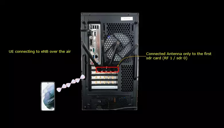
Test setup for this tutorial is as shown below.
- I used the default configuration(cfg) file without changing anything in it
- SIM Card used in this tutorial is the one delivered with the system as it is.
- If you want to change the configuration, The tutorial Configuration Guide would help
Configuration
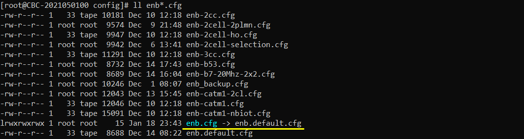
I used enb.default.cfg as the configuration for this tutorial but you may use any configuration as long as your DUT(UE) would support it.
IP configuration is set in mme.cfg (mme-ims.cfg which is the default configuration). Both IPv4 and IPv6 are configured by default. So I am just using the default configuration as it is.

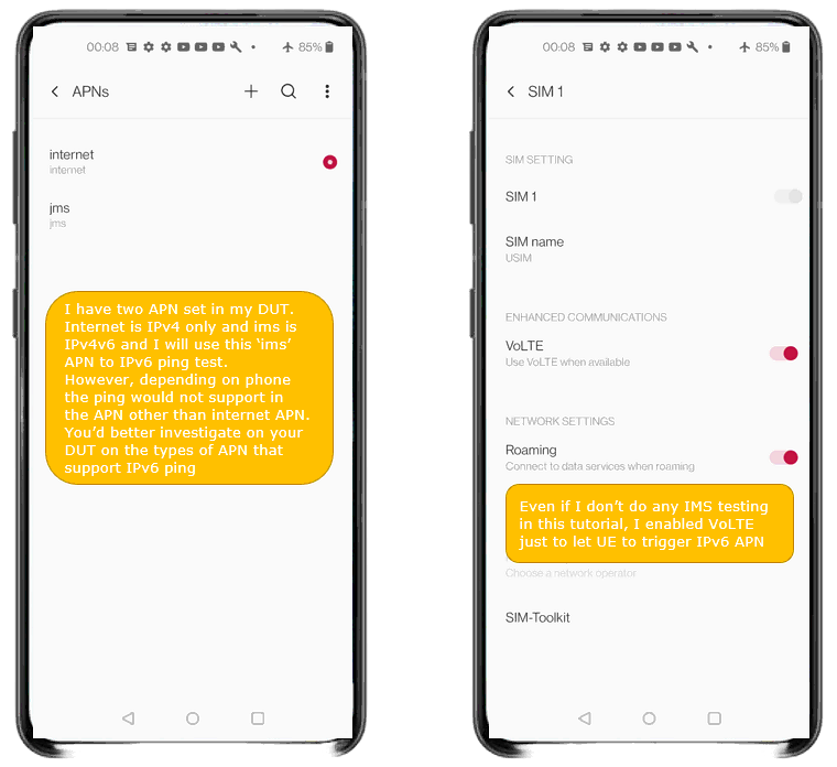
On UE side, I configured as below, but this configuration would vary depending on the mobile phone model or type of your DUT.
I have two APNs set in my DUT. internet is IPv4 only and ims is IPv4v6, and I used the ims APN for the IPv6 ping test. Depending on the phone, ping may not be supported on an APN other than the internet APN, so it is worth finding out on your own DUT which APN types allow an IPv6 ping before you spend time on the callbox side.
Even though I don't do any IMS testing in this tutorial, I enabled VoLTE in the SIM 1 settings just to let the UE trigger the IPv6 APN. Roaming is left on as well. If your phone never brings up the ims APN, enabling VoLTE is the first thing to try.
Check if LTE service is Running
Whatever you want to test, the first thing you need to do is that call box program (LTE Service) is running. You can check on the execution status of the call box program by running following command and you should get the result as shown below
# service lte status
The line to look at is Active, and it has to read active (running) in green. The unit is lte.service, described as Amarisoft LTE and loaded from /usr/lib/systemd/system/lte.service. It is enabled, so it comes back up by itself after a reboot, and the time at the end of the Active line tells you how long the current instance has been running.
The CGroup block at the bottom lists the processes that the service started, all of them /root/ots/ltestart.sh. This is the script that launches the individual modules such as MME and ENB inside the screen session that you attach to in the next step.
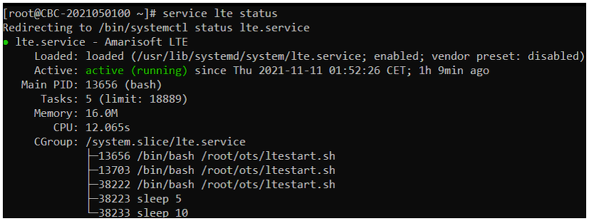
NOTE : Getting this result is pre-requisite for Call Box Operation, but this result itself does not guarantee the normal operation. If you see some unexpected issues. You may restart the call box with following command
# service lte restart
Run Screen
If it is confirmed that the lte service is running, go to screen mode by running 'screen -r' and follow through the steps as shown below. The steps shown here is the procedure that you would use for almost every test and it is highly recommended to get familiar with these steps. For further commands you can use in this screen mode, refer to the tutorial : Command Line Command
Run following command
Run it as root on the Callbox itself. screen -r does not start anything, it only reattaches you to the session that ltestart.sh already created when the lte service came up.

You will get the screen as shown below
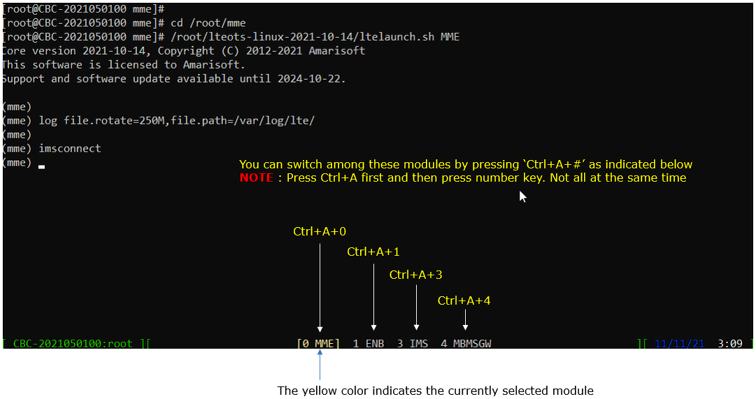
What comes up first is the [0 MME] window. The status bar at the bottom lists the four modules that the service runs, 0 MME, 1 ENB, 3 IMS and 4 MBMSGW, and the one shown in yellow is the module you are currently looking at. You move between them by pressing Ctrl+A first and then the number key, not all of them at the same time.
This MME window was started with ltelaunch.sh MME from /root/mme, and two commands have already been entered in it. log file.rotate=250M,file.path=/var/log/lte/ sets where the log file is written and how large it grows before it rotates, and imsconnect connects the MME to the IMS module. The IMS connection is what makes the [IMS] screen usable later, and that screen is where I read the UE IPv6 address back in this tutorial.
Switch to [ENB] by pressing �Ctrl + A + 1�. You will get the screen as shown below
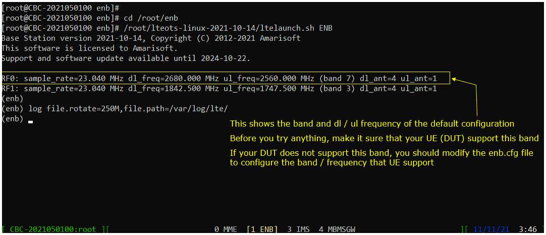
The two RF lines printed at startup are the ones to check. RF0 is on band 7 with dl_freq 2680.000 MHz and ul_freq 2560.000 MHz, and RF1 is on band 3 with dl_freq 1842.500 MHz and ul_freq 1747.500 MHz. Both run at sample_rate 23.040 MHz with dl_ant=4 and ul_ant=1.
Make sure your UE supports the band before you try anything else. If it does not, change the band and the frequency in enb.cfg to something the UE supports and restart the service, because the UE will never find the cell otherwise.
Start trace logging by 't' command as shown below .
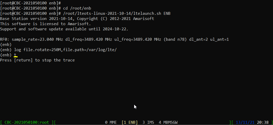
t is a toggle. Once it is entered the prompt replies with Press [return] to stop the trace, and from that point the physical layer and traffic prints for every connected UE keep scrolling in the window until you press return. Leave it running through the attach, because the PRACH print and the per UE traffic table in the next section only appear while the trace is on.
Attach
In this tutorial, it is assumed that you are familiar with how to get UE attached (Initial Attach) to Callbox. If you are completely new to Amari Callbox and never tried anything before, I would suggest you to try the tutorial LTE Attach first and get back to this tutorial.
Check on basic cell configuration and see if it is configured as you wanted (e.g, band, bw, RAT type etc)
cell phy gives the physical layer view. Cell 0x001 is an LTE cell on band 7 with 5 MHz bandwidth, downlink ARFCN 3350 with 2 antennas, 2 layers, 15 kHz subcarrier spacing and up to 256QAM, and uplink ARFCN 21350 with 2 antennas, 1 layer, 15 kHz subcarrier spacing and up to 64QAM. The SSB columns are empty because this is LTE and not NR.
cell gives the higher layer view of the same cell. TAC is 0x0001, dl_arfcn is 3350, pci is 1, prach_seq is 204 and dl_gain is 0.0. ul_dis is N, so the uplink is not disabled, and plmn is 00101 which matches the PLMN=00101 and eNB_ID=0x1a2d0 in the header line above.

Power On UE and let it complete the attach. (NOTE : You should see one or more PRACH print and several traffic prints as shown below).
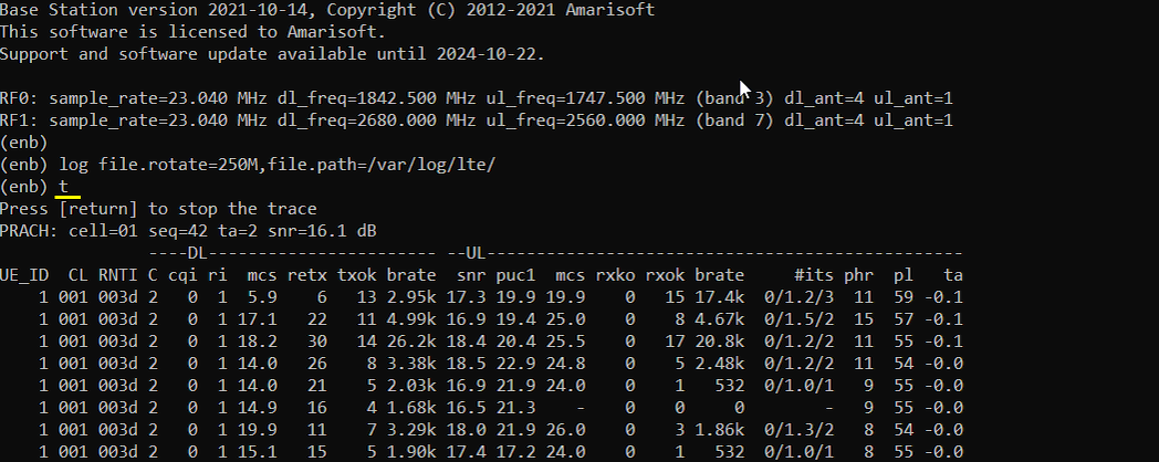
The PRACH print on (enb) screen is the first sign that the UE has found the cell. Mine reads PRACH: cell=01 seq=42 ta=2 snr=16.1 dB, so the preamble arrived on cell 1 with a timing advance of 2 and a signal to noise ratio of 16.1 dB.
After that the per UE traffic table starts scrolling. The UE is listed as UE_ID 1 on cell 001 with RNTI 003d, and the DL and UL sides each carry mcs, retransmission counts, transport block counts and bit rate. The DL mcs moves between 5.9 and 19.9 while the bit rates stay at a few kbps, which is what you get when there is no user traffic yet and only signalling is going through. phr stays around 8 to 15 and ta stays close to 0, so the link itself is fine. As long as these lines keep updating, the UE is attached and being scheduled.
When UE is in connected mode in RRC, you can check the ue status as follows (you don�t get any result when UE is in idle mode, but core network connection would still remain even after the rrc release if the initial attach was successful)
There is one entry, RAN_UE_ID 1 with CN_UE_ID 100, on cell 0x001 with RNTI 0x003d. The RNTI is the same 003d that appears in the traffic table above, which is how you tie a line in that table to a particular UE once more than one is connected.
CN_UE_ID is the identifier that the core network uses for the same UE, and it is the one that stays valid after the RRC connection is released. That is why an empty result here is not a failure by itself, and why the same command on the mme side still shows the UE with its IP addresses when this one shows nothing.

Figure Out UE and Server IP
Run the command [ue] in (mme) and it will show whether UE is assigned with any IP and what are those IPs. The IPs assigned to the UE is configured in mme.cfg file as indicated below.(
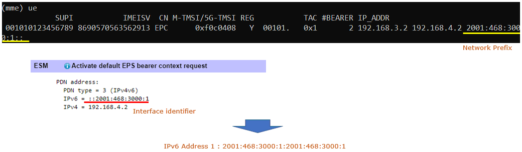
Make it sure that an IPv6 address is really assigned to the UE before going any further. The UE is listed with SUPI 001010123456789 and IMEISV 8690570563562913, CN is EPC, REG is Y and M-TMSI is 0xf0c0408. #BEARER is 2 and the IP_ADDR column carries three addresses, 192.168.3.2, 192.168.4.2 and 2001:468:3000:1::, so one bearer came up with IPv4 only and the other came up with both IPv4 and IPv6.
2001:468:3000:1:: is the one that matters for this tutorial. If that column shows IPv4 addresses only, the IPv6 PDN never came up and there is no point in hunting for an address on the UE screen. Go back to the APN setting on the phone and to the PDN type in mme.cfg first.

For IPv6 testing, I prefer checking users information on [IMS] screen. In may cases, many commercial UEs use IPv6 as default for IMS. So checking IMS status can be a quick and easy check if the IPv6 is working or not.
IMS registration is not mandatory for the ping test, but it is a good indicator that the IPv6 setup is complete. The SIP binding is registered on [2001:468:3000:1:5909:a3bd:9ee5:a9d0]:5060, so the UE has taken an address out of the same 2001:468:3000:1 prefix and is already using it as a source address for real traffic.
The rest of the entry is the identity part. IMPI is 001010123456789@ims.mnc001.mcc001.3gppnetwork.org, IMPU carries sip:001010123456789 together with tel:0600000000 and tel:600, Options is sms volte and Expires is 3520s. Keep the interface identifier 5909:a3bd:9ee5:a9d0 in mind, because it is not the one the network gave the UE in the NAS message and it turns into one of the ping candidates in the next section.

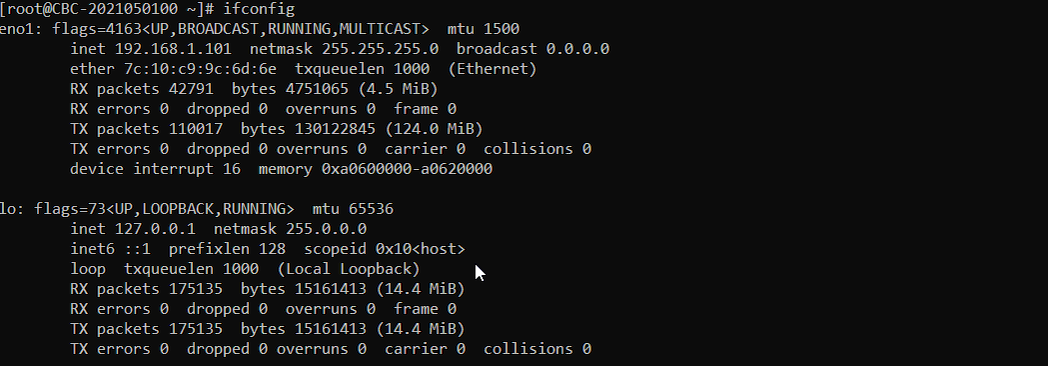
eno1 is the management interface of the box, on 192.168.1.101 with netmask 255.255.255.0 and mtu 1500, and it is the one I use to reach the Callbox over the LAN. It has no IPv6 address at all, so it plays no part in this test. lo below it is the loopback with 127.0.0.1 and inet6 ::1.
tun0, tun1 and tun2 are the tunnel interfaces created for the PDNs, and the address on each one is the network side of that PDN. tun0 is 192.168.2.1, tun1 is 192.168.3.1 and tun2 is 192.168.4.1, which lines up with the UE addresses from the ue output, 192.168.3.2 sitting behind tun1 and 192.168.4.2 sitting behind tun2.
tun2 is the one carrying IPv6. It has inet6 2001:468:3000:1:: with prefixlen 48 in global scope, the same prefix that was handed to the UE. tun0 and tun1 only have a link local fe80 address, so no global IPv6 is routed over those two and a ping sent to an address on this prefix leaves the box through tun2.
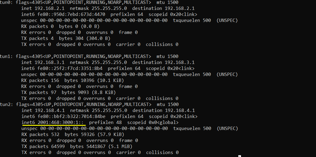
tun3 is set up the same way, 192.168.5.1 on the IPv4 side and inet6 2001:468:4000:1:: with prefixlen 48 in global scope. This is a second IPv6 capable PDN on a different prefix, 2001:468:4000 instead of 2001:468:3000, and it is not the one my UE ended up on. Which of the two you land on depends on which APN the UE brings up, so check the prefix in the ue output against these interfaces rather than assuming.
fe80::d942:b9c2:3d12:2bc4 on the same interface is the link local address of the Callbox side. It is not related to the link local address that the UE generates for itself, which shows up later as one of the ping candidates.

Figure out the IP to ping to
One of the challenging thing in IPv6 ping is to figure out the right IP address to use for Ping. Usually a few different IPv6 addresses are assigned once IPv6 Apn is established. Which IP allows Ping depends on UE implementation. So you need to know which IP to use for the ping test for your DUT
In this section, I will show you how to figure out some of the candidate IPv6s setup by UE (DUT). There may be another IP which is used for ping v6 by UE implementation but not shown here.
Candidate 1 : IPv6 address both network prefix assigned by Router Advertisement and interface id assigned by NAS message.
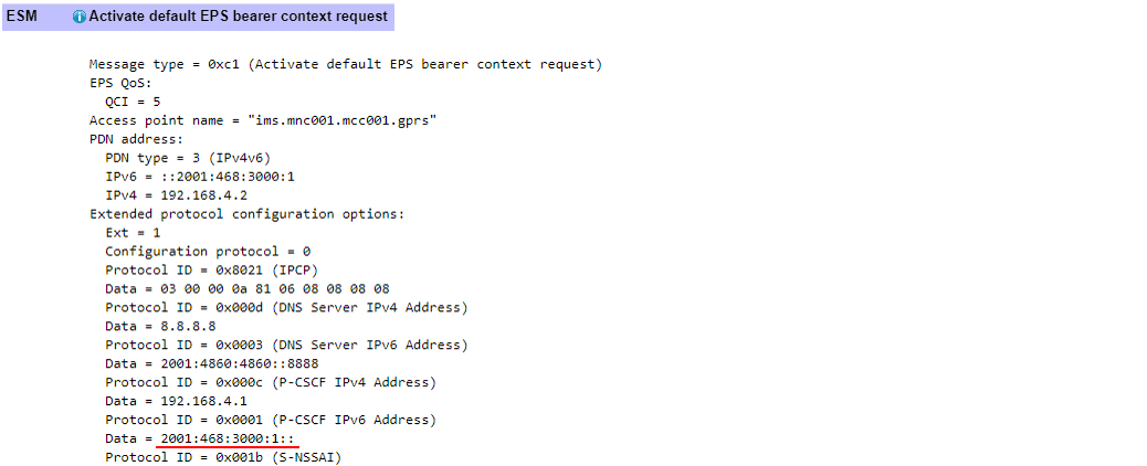
The prefix half is the 2001:468:3000:1:: value in the IP_ADDR column of the mme ue output. The interface identifier half comes from the Activate default EPS bearer context request, where the PDN address block reads PDN type = 3 (IPv4v6), IPv6 = ::2001:468:3000:1 and IPv4 = 192.168.4.2. The IPv6 field of a PDN address only carries the interface identifier and not a full address, which is why it is written with the leading colons.
Putting the two halves together gives 2001:468:3000:1:2001:468:3000:1. This is the address the network expects the UE to be using, and with the DUT in this tutorial it is the one that answered the ping.
Candidate 2 : IPv6 address used in SIP registration.
This one is 2001:468:3000:1:5909:a3bd:9ee5:a9d0. The prefix is the same 2001:468:3000:1, but the interface identifier 5909:a3bd:9ee5:a9d0 is a random one that the UE generated for itself instead of using the one it was given in the NAS message.
This is exactly the case I mentioned at the beginning of the tutorial. When a UE ignores the interface identifier from NAS and picks its own, the SIP binding in the ims users output is the easiest place to read the value back without touching the phone at all.

Candidate 3 : IPv6 address with local network prefix and interface id used in SIP registration.
This one is fe80::5909:a3bd:9ee5:a9d0. The interface identifier is the same random 5909:a3bd:9ee5:a9d0 taken from the SIP binding, but it is combined with the link local fe80 prefix instead of the global prefix.
A link local address is only reachable on the interface it lives on, so a ping to this candidate has to be sent out of the tunnel that the UE is on rather than left to the routing table. I keep it in the list because some UEs answer on the link local address when they do not answer on the global one.

Try ping
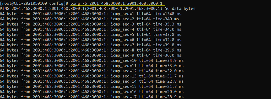
Once you figure out which IP out of all the candidates described above, you can try ping. With my DUT used in this tutorial, only following address allowed IPv6 ping.
The address that worked is candidate 1, and the command is ping -6 2001:468:3000:1:2001:468:3000:1 run from the Callbox shell. The -6 is what forces ping into IPv6 mode, and each request carries the default 56 data bytes.
The first reply comes back at 1348 ms and the second at 340 ms. That is the UE coming out of idle and the connection being set up again, and it is normal on the first packet. From icmp_seq=3 onwards the round trip time drops into the 20 to 40 ms range and stays there, with 64 bytes returned each time and ttl=64. No sequence number is missing, so every request is getting through.
If your UE does not answer on this address, work down the other two candidates. Which one replies depends on the UE implementation, and none of them replying usually points at something on the UE side rather than on the Callbox.
Tips
Figureing Out Network Prefix
There might be some cases where you get only interface identifier (the last 32 bits of IPv6 address) displayed on your UE and you want to figure out the network prefix (the first 32 bits of IPv6 address) to get the full IPv6 address. One way to figure the network prefix is to find it from a NAS message as shown below. Then, you can get the full 64bits IPv6 address by combining the network prefix and interface identifier.
The message to look for is Activate default EPS bearer context request, message type 0xc1. In my case it is sent for the ims APN, with Access point name = "ims.mnc001.mcc001.gprs" and QCI = 5, and the PDN address block reads PDN type = 3 (IPv4v6) with IPv6 = ::2001:468:3000:1 and IPv4 = 192.168.4.2.
The prefix itself is easiest to read out of the Extended protocol configuration options at the bottom. Protocol ID = 0x0001 (P-CSCF IPv6 Address) carries 2001:468:3000:1::, and since the P-CSCF sits on the same PDN as the UE, that value gives you the prefix half to combine with the interface identifier you read off the UE.
The same block also hands over the addresses that the UE needs for everything else on that PDN. Protocol ID = 0x000d (DNS Server IPv4 Address) is 8.8.8.8 and Protocol ID = 0x0003 (DNS Server IPv6 Address) is 2001:4860:4860::8888, while Protocol ID = 0x000c (P-CSCF IPv4 Address) is 192.168.4.1. All of these come from the pdn_list entry of the matching access_point_name in mme.cfg, the two DNS addresses from dns_addr and the two P-CSCF addresses from p_cscf_addr, so that is where you change them if you want a different set.
IPv6 Verficiation with Amari UEsim
As far as we experienced, most of IPv6 setup issue turned out to be due to UE side issues as follows (this is just a few examples).
- UE side implementation was not correct
- UE side implementation is correct but does not provide proper measures to present IPv6 address via user interface
- UE side implementation is correct but some features (e.g, ICMP) was blocked by firewall
We suggest users to have proper debugging tools on UE side to check the detailed status / procedure of IPv6. Amarisoft does not have any debugging tools for commercial device (or any other customer UE). The only way we can verify the operation of IPv6 is to use Amarisoft Callbox and Amarisoft UE simulator. Followings are tutorials showing how we can validate IPv6 with Amarisoft Product. You may not be able to verify as we do if you don't have Amarisoft UEsim + Amarisoft Callbox, but the point is that these verification would be good indicators that Amarisoft IPv6 stack works properly.