
Out of the Box Test - Ping
The purpose of this tutorial is to show you how to do IPv4 ping from Amari Callbox to UE. It is assumed that you don't have any previous experience with Amari callbox. For IPv6 ping, refer to another tutorial : Ping IPv6.
I don't think I need to explain on what is ping since everybody would know it. I think more important thing is why we do ping test and what are the things to be considered about the ping test. For any kind of data related test, for example, udp throughput (udp flooding), tcp throughput (tcp flooding), ftp(file download/upload) or streaming (e.g, YouTube streaming), the first thing you have to make it sure is that the required data pipe is properly established and the simplest way to check if the data pipe is established or not is to use ping test. Regarding the ping test, I would suggest to check a few things listed below.
- Check if the firewall on server (ping sender) and client (ping reciever) allows both incoming and outgoing ping(ICMP). Even if the data pipe is properly established, I see cases where ping does not go through due to the firewall setting.
- Check ping RTT. If your purpose is just to check whether the data pipe is established or not, just to make ping success would be enough. But if your final goal is to achieve maximum throughput at IP layer, you should make it sure that you get the shortest RTT that are allowed by the specific radio access network.
If the ping does not go through, refer to the ping throubleshoot Tips section.
Table of Contents
Introduction
In mobile communication networks, establishing reliable data connectivity between the User Equipment (UE) and the radio access infrastructure is fundamental for enabling a wide range of services—from web browsing and file transfers to voice over IP and media streaming. The Amari Callbox is a versatile and widely used test platform that emulates a complete cellular network environment, allowing engineers and researchers to validate and troubleshoot wireless connectivity scenarios in a controlled setting. One of the most essential diagnostic tools in this context is the Internet Control Message Protocol (ICMP) ping test, which is used to verify the integrity and performance of the IP data path between network elements. Conducting an IPv4 ping from the Amari Callbox to a UE involves multiple architectural layers, including the radio interface, the core network, and the IP stack, each contributing to the overall end-to-end communication process. The significance of the ping test lies in its ability to quickly confirm successful bearer establishment, identify potential misconfigurations, and measure round-trip times (RTT), which are indicative of the quality and responsiveness of the underlying network. This tutorial provides a step-by-step guide for executing IPv4 ping tests in the Amari Callbox environment, offering insights into test setup, configuration considerations, and troubleshooting best practices. By understanding the underlying mechanisms and implications of the ping test, practitioners can ensure robust data connectivity and lay the groundwork for further performance evaluations such as throughput benchmarking and application-level testing.
-
Context and Technology Overview
- The Amari Callbox simulates a complete cellular network, including radio access and core network functionalities, enabling comprehensive testing of UE connectivity and data transfer scenarios.
- ICMP ping operates at the network layer and is commonly used to test IP connectivity, measure latency, and ensure that the UE has successfully established an end-to-end data path through the simulated network.
- The IPv4 protocol stack underpins the communication, leveraging dynamic bearer establishment, routing, and address assignment mechanisms integral to both the radio network and the core IP infrastructure.
-
Relevance and Importance of the Tutorial
- Verifying IP connectivity via ping is a foundational step in any data service validation, preceding more complex throughput or application-layer tests.
- Successful ping tests confirm the correct setup of the data path, including radio bearers, IP routing, and firewall configurations, helping to quickly isolate issues in network setup.
- The tutorial addresses not only how to perform the ping test but also why it is essential for subsequent network performance analysis and troubleshooting.
-
What Learners Will Gain
- Step-by-step instructions for configuring and executing IPv4 ping tests from the Amari Callbox to a UE.
- Practical guidance on verifying network setup, interpreting ping results, and understanding common failure points.
- Insights into best practices for troubleshooting connectivity issues and optimizing network settings for reliable data transfer.
- A foundation for extending the methodology to more advanced tests, such as throughput measurements and application-level diagnostics.
-
Prerequisite Knowledge and Skills
- Basic familiarity with IP networking concepts and test tools (e.g., understanding of ping, IP addresses, and ICMP).
- General understanding of cellular network architecture (radio access network, core network, UE).
- No prior experience with the Amari Callbox is required; the tutorial is designed for beginners and provides necessary context for first-time users.
Summary of the Tutorial
This tutorial outlines the procedure for conducting an out-of-the-box LTE connectivity and IP traffic test using the Amari Callbox and a UE (User Equipment). The following steps and methodologies are described:
-
Test Setup
- Utilize the default configuration file with no modifications for out-of-the-box testing.
- Use the SIM card supplied with the system.
- If configuration changes are needed, refer to the linked Configuration Guide.
-
Configuration
- Ensure the eNB and MME configuration files are properly linked to their default versions (e.g., linking enb.default.cfg to enb.cfg).
- For MME, link mme-ims.cfg to mme.cfg and ims.default.cfg to ims.cfg as needed using ln -sf commands.
- Verify the presence of the correct configuration links in their respective directories.
-
Check if LTE Service is Running
- Run service lte status to confirm the LTE service is operational.
- If issues are found, restart the service with service lte restart.
-
Run Screen
- Attach to the screen session using screen -r to access the Callbox’s network components.
- Switch between components (e.g., ENB, MME) using Ctrl+A and the corresponding number shown in the interface.
- In the ENB window, review displayed RF configuration parameters for verification (sample_rate, dl_freq, ul_freq, band, etc.).
- Start trace logging by pressing t before powering on the UE to capture the complete attach process.
-
Attach Procedure
- Power on the UE and allow it to perform the initial attach to the Callbox.
- Monitor trace logs for PRACH attempts and successful RACH completion, which indicate a successful attach and readiness for IP traffic.
-
Figure Out UE and Server IP
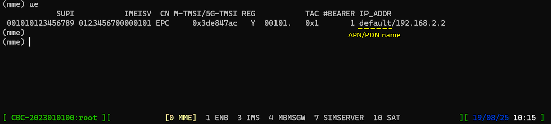
- In the MME command window, use the [ue] command to verify IP assignment to the UE. Confirm the assigned IPs correspond to configurations in mme.cfg.
- Ensure that the Callbox has active network interfaces for IP communication with the UE (e.g., verify tun0, tun1, etc. interfaces are up).
- Check that network interfaces with internet connectivity are operational.
-
Ping Test Procedures
- From the Callbox, initiate a ping to the UE’s assigned IP address to verify downlink IP connectivity.
- From the UE, use an appropriate ping application to send ICMP echo requests to the Callbox IP address to verify uplink IP connectivity.
- If the UE has multiple IP addresses (e.g., for internet and IMS PDNs), test both as some implementations may restrict ping on IMS PDNs.
-
Troubleshooting Tips
-
If ping fails:
- Verify that all required signaling and bearer setup procedures have completed.
- Check radio link conditions for excessive errors.
- Ensure correct IP addresses are used in ping commands.
- Verify that firewalls on both UE and Callbox permit ICMP traffic in both directions.
-
If ping fails:
This methodology ensures the out-of-the-box LTE system is functioning correctly and verifies IP connectivity between the Callbox and the UE through systematic configuration verification, service checks, initial attach monitoring, network interface validation, and bidirectional ping testing.
Test Setup
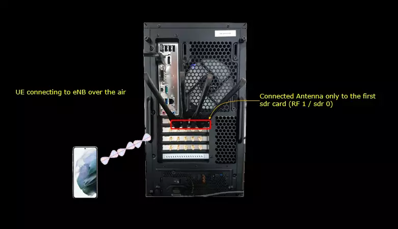
Test setup for this tutorial is as shown below.
- Since this test is for Out of the box testing, I used the default configuration(cfg) file without changing anything in it
- SIM Card used in this tutorial is the one delivered with the system as it is.
- If you want to change the configuration, The tutorial Configuration Guide would help
I connected the UE to the eNB over the air. The antennas are connected only to the first SDR card, identified as RF 1 / sdr 0.
Configuration
This test can be done with any configuration that assigns any one or more IP address to the UE. If you just want to use what I have used for this tutorial, you can do as follows.
Go to the directory /root/enb/config and make a symbolic link as follows. (

Now you should see the enb.cfg file linked to enb.default.cfg as follows.

Now go to the directory /root/mme/config. You should see the configuration files as below.
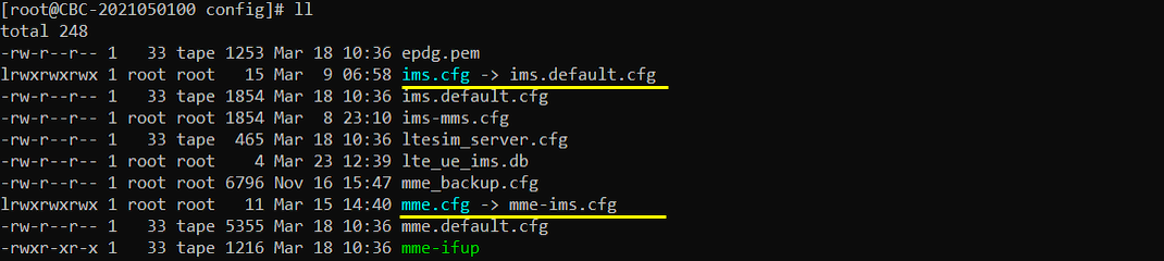
If ims.cfg and mme.cfg is not linked to the files as shown above, you may run following commands to make proper link.
"ln -sf mme-ims.cfg mme.cfg" mean 'link mme-ims.cfg to mme.cfg' and "ln -sf ims.default.cfg ims.cfg" mean "link ims.default.cfg to ims.cfg"

Check if LTE service is Running
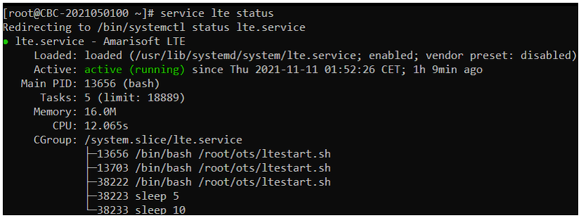
Whatever you want to test, the first thing you need to do is that call box program (LTE Service) is running. You can check on the execution status of the call box program by running following command and you should get the result as shown below
# service lte status
The Active field reports active (running), and the Loaded field reports that lte.service is enabled. The process list includes /root/ots/ltestart.sh.
# service lte restart
Run Screen
If it is confirmed that the lte service is running, go to screen mode by running 'screen -r' and follow through the steps as shown below. The steps shown here is the procedure that you would use for almost every test and it is highly recommended to get familiar with these steps. For further commands you can use in this screen mode, refer to the tutorial : Command Line Command
Run following command
I enter screen -r at the Linux shell prompt. After attaching, I can select the component console needed for the next step.

You will get the screen as shown below.
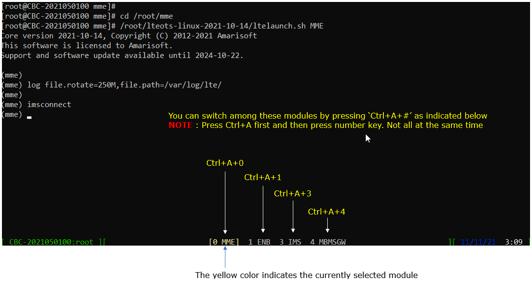
This screen shows all the network components installed in the callbox. In this tutorial, it indicates MME, ENB, IMS, MBMSGW are installed in the callbox. You would see a number before each component name. With Ctrl+A and the number before the component name, you can switch to command line window for the specific component. For example, if you press Ctrl+A+1, the command line window switches to ENB and if you press Ctrl+A+0, the command line window switches to MME and so on.
Press Ctrl+A first, release the keys, and then press the component number. Do not press all three keys at the same time.
The selected component is marked in yellow in the bottom bar. Here, 0 selects MME, 1 selects ENB, 3 selects IMS, and 4 selects MBMSGW.
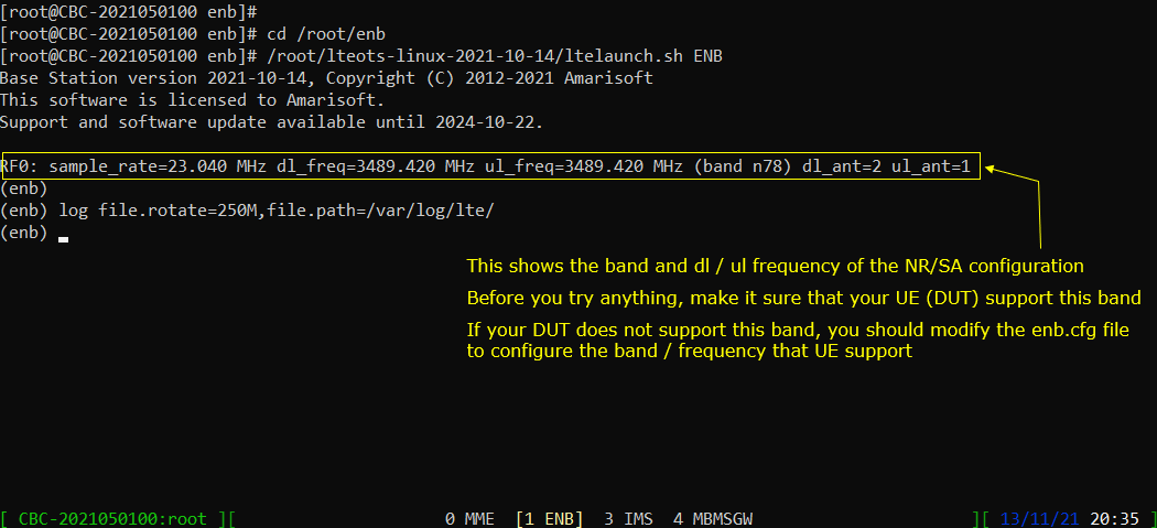
Switch to [ENB] by pressing { Ctrl + A + 1 }. You will get the screen as shown below, When you switches to [ENB] there are some important information provided without running any specific command. It provides RF information showing the sample_rate, dl_freq, ul_freq, band, dl_ant, ul_ant that gives you very fundamental RF information. Check out the details of these info and see if the RF is configured as you intended.
This console example uses NR SA on band n78. RF0 reports sample_rate=23.040 MHz, dl_freq=3489.420 MHz, and ul_freq=3489.420 MHz. The antenna counts are dl_ant=2 and ul_ant=1.
Check that your UE supports the configured band before starting the test. If it does not, change enb.cfg to use a band and frequency supported by your UE.
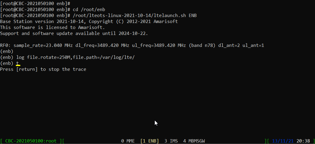
Start trace logging by 't' command as shown below . You can run this command any time during the test, but it is always good idea to run this command before you power on UE to get the log from very beginning of initial attach.
I enter t at the (enb) prompt. The console then prints Press [return] to stop the trace. Press Return when you want to stop this console trace.
Attach
In this tutorial, it is assumed that you are familiar with how to get UE attached (Initial Attach) to Callbox. If you are completely new to Amari Callbox and never tried anything before, I would suggest you to try the tutorial LTE Attach first and get back to this tutorial.
Power On UE and let it complete the attach. If you started 't' command before you powe on UE, you will get the traces for PRACH attempt. The presence of PRACH trace can be a good troubleshooting indicator for initial attach problem. If PRACH is properly received and the entire RACH process is completed, it is highly likely that the initial attach gets completed and start getting traffic log. Regarding the details on the meaning of each column of this log and how to use the information for troubleshoot, refer to this tutorial.
This attach example uses LTE band 3 on RF0 and band 7 on RF1. The earlier console example used NR band n78.
The PRACH entry reports cell=01, seq=42, ta=2, and snr=16.1 dB. The following rows contain DL and UL statistics for UE ID 1, cell 001, and RNTI 003d.
The first statistics row has a DL bitrate of 2.95k and a UL bitrate of 17.4k. I check the assigned IP addresses in MME next.
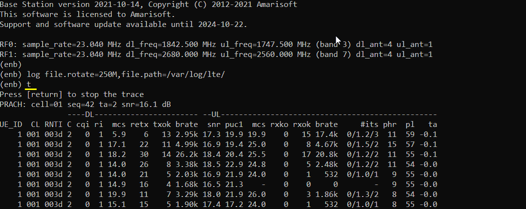
Figure Out UE and Server IP
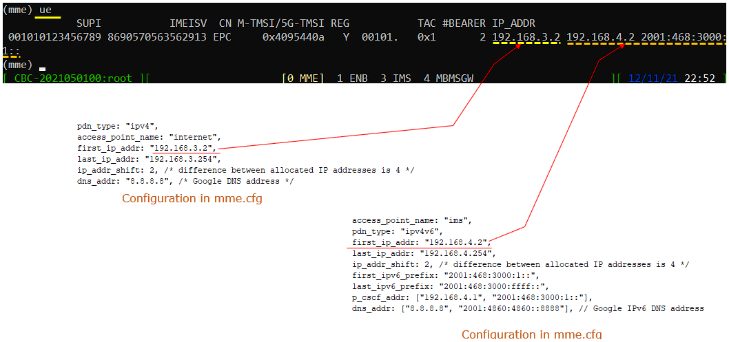
Run the command [ue] in (mme) and it will show whether UE is assigned with any IP and what are those IPs. The IPs assigned to the UE is configured in mme.cfg file as indicated below.(
The ue result lists CN as EPC, REG as Y, and #BEARER as 2. The assigned IPv4 addresses are 192.168.3.2 and 192.168.4.2.
The internet entry uses access_point_name: "internet" and pdn_type: "ipv4". Its first_ip_addr is "192.168.3.2", and last_ip_addr is "192.168.3.254". The ims entry uses access_point_name: "ims" and pdn_type: "ipv4v6". Its IPv4 range runs from first_ip_addr: "192.168.4.2" to last_ip_addr: "192.168.4.254".
Both entries use ip_addr_shift: 2, giving a spacing of four between allocated IPv4 addresses. Use the address reported by ue as your ping destination if your allocation differs.
The IP_ADDR field reads default/192.168.2.2. Here, default is the APN/PDN name and 192.168.2.2 is the assigned UE address.
This example has #BEARER set to 1 and REG set to Y. It uses a different PDN and address from the internet and ims example above.
Make it sure that the call box has network interface that is required for IP traffic with UE.
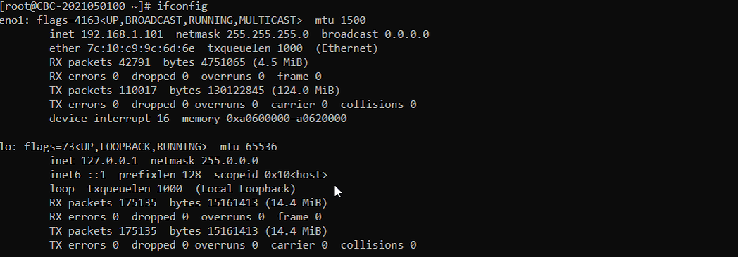
Following is the whole result of [ifconfig] on my Callbox. These are some of the network interface automatically setup by Operating system (Fedora on Amari Callbox Classic in my case). These are not directly involved in IP traffics with UE
The eno1 interface has IPv4 address 192.168.1.101 and netmask 255.255.255.0. The lo interface has IPv4 address 127.0.0.1. Both interfaces report UP and RUNNING.
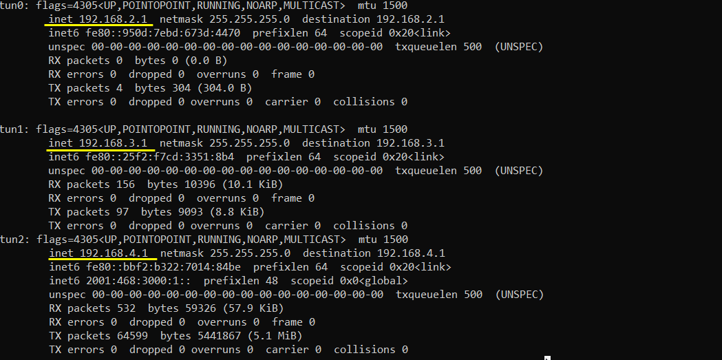
Make it sure that the network interface with internet connectivity is up and tun0,1,2,3 are up. You may see different name in your setup. The interface tun0,1,2,3 are network interface crated by Callbox. The IP assigned to these interfaces are configured in /root/mme/config/mme.cfg
The Callbox addresses are 192.168.2.1 on tun0, 192.168.3.1 on tun1, and 192.168.4.1 on tun2. All three interfaces report UP and RUNNING, with netmask 255.255.255.0 and mtu 1500.
I use 192.168.3.1 and 192.168.4.1 as the Callbox destinations for the UE ping tests later. These correspond to the subnets containing UE addresses 192.168.3.2 and 192.168.4.2. The remaining interface, tun3, has IPv4 address 192.168.5.1 and netmask 255.255.255.0. It also reports UP and RUNNING, with mtu 1500. The ping examples below use the tun1 and tun2 subnets.

Try ping
Now you can try ping on Callbox to the IP that is assigned to the UE.
I used 192.168.4.2, the UE address assigned to the ims PDN, as the destination. Replies arrive for icmp_seq=1 through icmp_seq=8, each reporting 64 bytes and ttl=255.
The first two replies take 1326 ms and 287 ms. The remaining replies range from 34.0 ms to 38.2 ms. This run has no final ping statistics displayed.

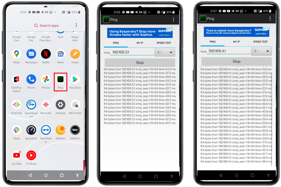
Then try ping from UE to Callbox. I downloaded and installed an Android Ping App on the UE for test. You may use any other App that is capable of ping test.
I entered 192.168.3.1 in the Host field for one test and 192.168.4.1 for the other. These are the Callbox addresses on tun1 and tun2.
Both tests receive 64-byte replies with ttl=64. The reply lines include icmp_seq and time, so you can check successive replies and their round-trip times.
Troubleshoot Tips
If ping does not go through, I would suggest you to check on followings.
- Check if the protocol (RRC/NAS signaling) required for ping are all gone through (especially check if EPS bearer setup is complete in LTE and PDU session is established in NR)
- Check if the radio link condition is good enough for user traffic. If you are getting too many CRC errors for PDSCH or PUSCH, the ping would not go through.
- Check if the destination IP is properly specified in your ping command
- Check if the firewall on both sender and reciever allows both incoming and outgoing ICMP