Out of the Box Test - NR SA
The purpose of this tutorial is to show you how to establish NR SA connectionbetween a UE and Amari Callbox. It is assumed that you don't have any previous experience with Amari callbox.
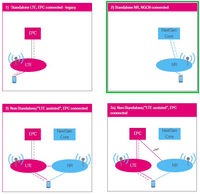
SA stands for "Stand Alone". "Stand Alone" in NR SA implies two things as below
- It support NR without any help of other technology (e.g, LTE)
- It supports NR Core Network and NR RAN directly connected to NR Core network.
According to NR deployment options described in RP-161266, NR SA corresponds to Option 2) as highlighted in green box below (
In terms of the frequency and bands, Amarisoft Callbox (gNB) support all the frequencies and bands that are specified in 3GPP. In terms of bandwidth, Amarisoft Callbox (gNB) support any 3gpp defined band upto 100Mhz per component carrieras of now.
Table of Contents
- Out of the Box Test - NR SA
- Introduction
- Summary of the Tutorial
- Test Setup
- Key Configuration Parameters
- Configuration
- Check if LTE service is Running
- Perform the Test
- Log Analysis
- RRC / NAS Signaling
- SIB1
- RrcSetup
- Registration Request
- Registration Accept
- PDU Session Establishment Request
- PDU Session Establishment Accept
- Troubleshoot
Introduction
The evolution of mobile communication networks has reached a pivotal point with the deployment of 5G New Radio (NR) Standalone (SA) architecture, which enables end-to-end 5G connectivity without reliance on legacy technologies such as LTE. NR SA represents a significant advancement over previous deployment options, as it leverages a dedicated NR Core Network (5GC) and NR Radio Access Network (NR RAN), facilitating low latency, high throughput, and network slicing capabilities fundamental to next-generation applications. In this context, the Amari Callbox by Amarisoft emerges as a versatile and powerful solution for testing, validating, and experimenting with NR SA connections. The Amari Callbox integrates a software-defined radio platform capable of emulating both the NR RAN (gNB) and the NR Core Network, supporting all 3GPP-specified frequency bands and bandwidths up to 100 MHz per component carrier. This enables comprehensive end-to-end testing of User Equipment (UE) in a controlled environment, accelerating development cycles and ensuring conformance to industry standards. By establishing an NR SA connection between a UE and the Amari Callbox, users can gain practical insight into 5G protocols, signaling procedures, and network behavior, which are critical for engineers, researchers, and network operators involved in the 5G ecosystem. The tutorial provides a step-by-step guide for users with no prior experience with the Amari Callbox, demystifying the setup and configuration required to achieve a successful NR SA connection and illustrating the broader implications of standalone 5G deployments in real-world scenarios.
-
Context and Background
- 5G NR SA Overview: Standalone (SA) mode in 5G NR refers to a network architecture where both the Radio Access Network (gNB) and the Core Network (5GC) are based on 5G technologies, without dependency on LTE EPC or eNodeB.
- Industry Relevance: NR SA (Option 2) is widely recognized for enabling the full suite of 5G features, such as network slicing, ultra-reliable low-latency communications (URLLC), and massive machine-type communications (mMTC).
- Amari Callbox Solution: The Amari Callbox is a self-contained, software-defined radio platform supporting both LTE and NR core networks, capable of emulating any 3GPP-defined frequency band up to 100 MHz per component carrier.
-
Relevance and Importance of the Tutorial
- Hands-on Experience: Guides users through practical steps to establish and troubleshoot NR SA connectivity, bridging the gap between theoretical knowledge and real-world application.
- Accelerated Development: Enables rapid prototyping, validation, and debugging of 5G NR features using a flexible test platform.
- Industry Alignment: Prepares engineers and researchers for evolving 5G standards and deployment models adopted globally.
-
What Learners Will Gain
- Technical Proficiency: Understanding of NR SA architecture, protocol stack, and signaling flows between UE and 5G core network.
- Practical Skills: Step-by-step instructions for configuring Amari Callbox, initiating NR SA connections, and interpreting diagnostic information.
- Troubleshooting Techniques: Ability to diagnose and resolve common issues encountered during NR SA connection attempts.
-
Prerequisite Knowledge and Skills
- Basic Networking Concepts: Familiarity with IP addressing, network interfaces, and general connectivity principles is helpful but not required.
- 5G NR Fundamentals: Prior knowledge of 5G NR concepts is beneficial but the tutorial is structured to accommodate users new to Amari Callbox and NR SA deployments.
- System Access: Access to Amari Callbox hardware/software and a compatible 5G NR-capable UE are required for hands-on exercises.
Summary of the Tutorial
This tutorial outlines the procedures for conducting an "Out of the Box" Standalone (SA) NR test using Amarisoft equipment and default configurations. The steps cover setup, execution, logging, log analysis, signaling review, and troubleshooting. The following summarizes the key test procedures and methodologies described:
-
Test Setup and Configuration
- Use the default configuration file gnb-sa.cfg for the gNB, with no modifications.
- Utilize the SIM card provided with the system as-is.
- Key configuration parameters include nr_cell_list.band, dl_nr_arfcn, subcarrier_spacing, ssb_pos_bitmap, nr_cell_default.bandwidth, n_antenna_dl, n_antenna_ul, tdd_ul_dl_config, and ssb_period.
- To apply the desired configuration, set up symbolic links:
- In /root/enb/config, link enb.cfg to gnb-sa.cfg using
ln -sf gnb-sa.cfg enb.cfg. - In /root/mme/config, ensure ims.cfg points to ims.default.cfg and mme.cfg to mme-ims.cfg via symbolic links.
- In /root/enb/config, link enb.cfg to gnb-sa.cfg using
- Restart the callbox to apply new configurations using
service lte restart. - Verify LTE service status with
service lte statusbefore proceeding.
-
Test Execution
- Access the call box interface using
screen -rto monitor and interact with network components (MME, ENB, IMS, MBMSGW). - Switch to the ENB component using Ctrl + A + 1 for detailed RF and network status.
- Begin trace logging by pressing t prior to powering on the User Equipment (UE) to capture the full attach sequence, including PRACH attempts.
- Power on the UE and allow it to complete initial attach and SA establishment.
- Stop trace logging by pressing the Enter key and return to the command prompt for further actions.
- Access the call box interface using
-
Log Analysis
- Open the generated log file (e.g., /tmp/gnb0.log) using a text editor.
- Verify the presence and sequence of key signaling messages:
- Check for RRC Setup Request and RRC Setup to confirm successful cell search and PRACH completion.
- Ensure RRC Setup Complete is received, indicating the UE completed setup.
- Monitor for authentication messages; analyze Authentication Response or Failure for SIM parameter mismatches.
- Confirm NAS and RRC security completion via Security mode complete messages.
- Check for RRC Reconfiguration and Reconfiguration Complete.
- Verify 5GMM: Registration complete and PDU Session Establishment procedures, including correct IP and DNS assignment to UE.
- For detailed analysis, use the WebGUI as recommended.
-
Signaling and Message Structure Review
- Sample structures of SIB1, RRC Setup, Registration Request/Accept, and PDU Session Establishment Request/Accept messages are provided for reference.
- Identify and interpret important Information Elements (IEs) for troubleshooting and validation of the signaling flow.
-
Troubleshooting Procedures
- If UE fails to camp on SA, perform the following checks:
- Test with NSA mode to validate UE capability.
- Review UE capability information from LTE/NSA logs for NR SA support.
- Compare supported bandwidth and subcarrier spacing with configuration files.
- Investigate known commercial UE issues related to SA operation, especially with test USIMs.
- Reference provided signaling IEs and troubleshooting guides for further diagnosis of registration or attach failures.
- If UE fails to camp on SA, perform the following checks:
This procedure ensures a comprehensive, step-by-step validation of Standalone NR operation using Amarisoft solutions in an out-of-the-box configuration, with guidance on configuration, execution, logging, analysis, and troubleshooting.
Test Setup
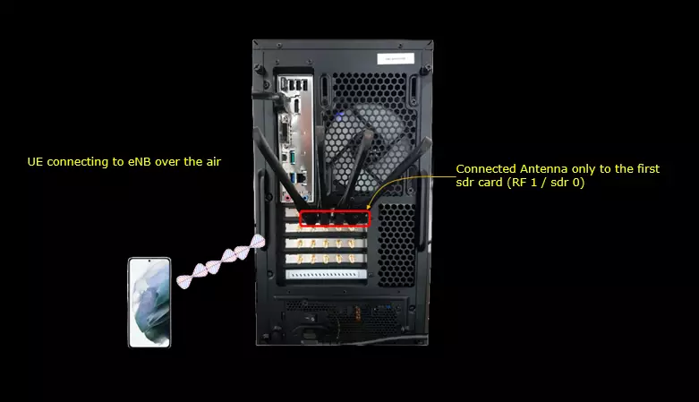
Test setup for this tutorial is as shown below.
- Since this test is for Out of the box testing, I used the SA default configuration(gnb-sa.cfg) file without changing anything in it
- SIM Card used in this tutorial is the one delivered with the system as it is.
- If you want to change the configuration, The tutorial Configuration Guidewould help
Key Configuration Parameters
Followings are important configuration parameters for this tutorial. You may click on the items for the descriptions from Amarisoft documents.
Configuration
In this section, I would show you how to change the configuration file that is used by eNB/gNB. But in this very basic tutorial (Out of the Box Test), I would not try to change the detailed configuration within the file and will just replace the enb.cfg with another file.
Go to eNB/gNB configuration directory

Change the symbolic link so that enb.cfg points to { enb.cfg -> gnb-sa.cfg }using the command : "ln -sf gnb-sa.cfg enb.cfg"

Now you should see the enb.cfg is linked to gnb-sa.cfg as shown below.(

Now go to the directory /root/mme/config. You should see the configuration files as below. (

If ims.cfg and mme.cfg is not linked to the files as shown above, you may run following commands to make proper link : "ln -sf ims.default.cfg ims.cfg" and "ln -sf mme-ims.cfg mme.cfg
![]()
Restart the callbox so that the new configuration file is applied : try with 'service lte restart'

Check if LTE service is Running
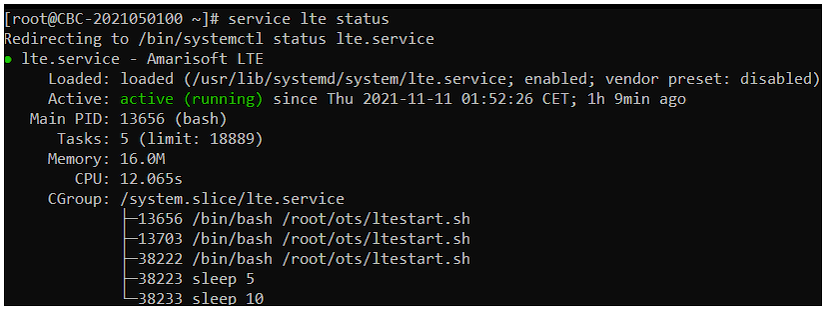
Whatever you want to test, the first thing you need to do is that call box program (LTE Service) is running. You can check on the execution status of the call box program by running following command and you should get the result as shown below
# service lte status
# service lte restart
Perform the Test
If it is confirmed that the lte service is running, go to screen mode by running 'screen -r' and follow through the steps as shown below. The steps shown here is the procedure that you would use for almost every test and it is highly recommended to get familiar with these steps. For further commands you can use in this screen mode, refer to the tutorial : Command Line Command
Run following command : "screen -r"

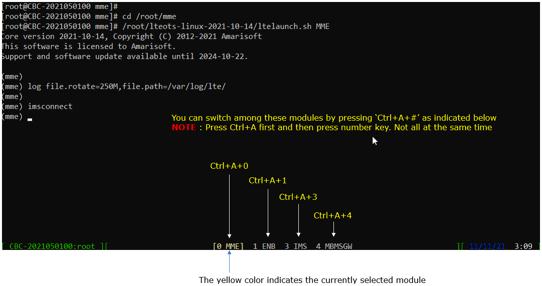
You will get the screen as shown below
This screen shows all the network components installed in the callbox. In this tutorial, it indicates MME, ENB, IMS, MBMSGW are installed in the callbox. You would see a number before each component name. With Ctrl+A and the number before the component name, you can switch to command line window for the specific component. For example, if you press Ctrl+A+1, the command line window switches to ENB and if you press Ctrl+A+0, the command line window switches to MME and so on.
Switch to [ENB] by pressing ‘Ctrl + A + 1’. You will get the screen as shown below.
When you switches to [ENB] there are some important information provided without running any specific command. It provides RF information showing the sample_rate, dl_freq, ul_freq, band, dl_ant, ul_ant that gives you very fundamental RF information. Check out the details of these info and see if the RF is configured as you intended.
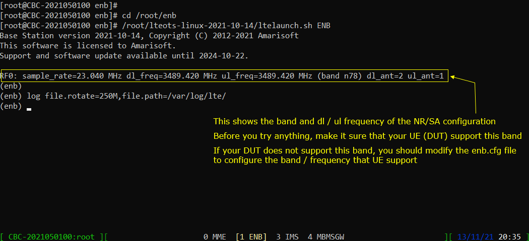
Start trace logging by 't' command as shown below.
You can run this command any time during the test, but it is always good idea to run this command before you power on UE to get the log from very beginning of initial attach.
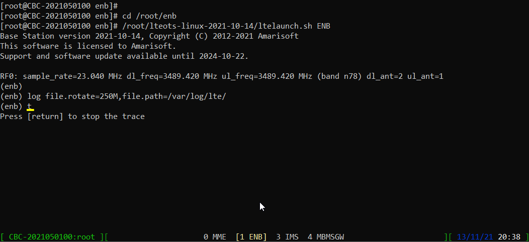
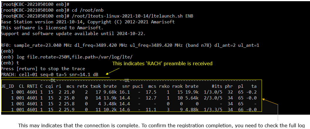
Power On UE and let it complete the attach and SA establishment. You would get trace as shown below.
If you started 't' command before you powe on UE, you will get the traces for PRACH attempt. The presence of PRACH trace can be a good troubleshooting indicator for initial attach problem. If PRACH is properly received and the entire RACH process is completed, it is highly likely that the initial attach gets completed and start getting traffic log. Regarding the details on the meaning of each column of this log and how to use the information for troubleshoot, refer tothis tutorial.
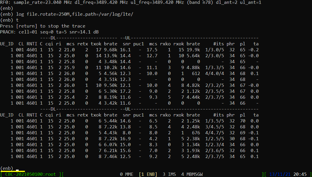
Press [Enter] key to stop the trace logging. When you want to use another command, you need to stop 't' command by pressing the enter key and get back to prompt as shown below.
Log Analysis
In this section, you will see how to confirm if UE registration is complete from trace log. You can use the same method to find any issues (e.g, registration failure) for troubleshooting. When UE registration fails, you may use this tutorial to figure out the point of the failure and troubleshoot
NOTE : This section is just to check quickly some important points in the log, but it may be a little bit tricky to do the detailed log analysis (especially for lower layer log analysis). In that case, I strongly recommend you to use WebGUI for the log analysis. You may refer to WebGUI Tutorial
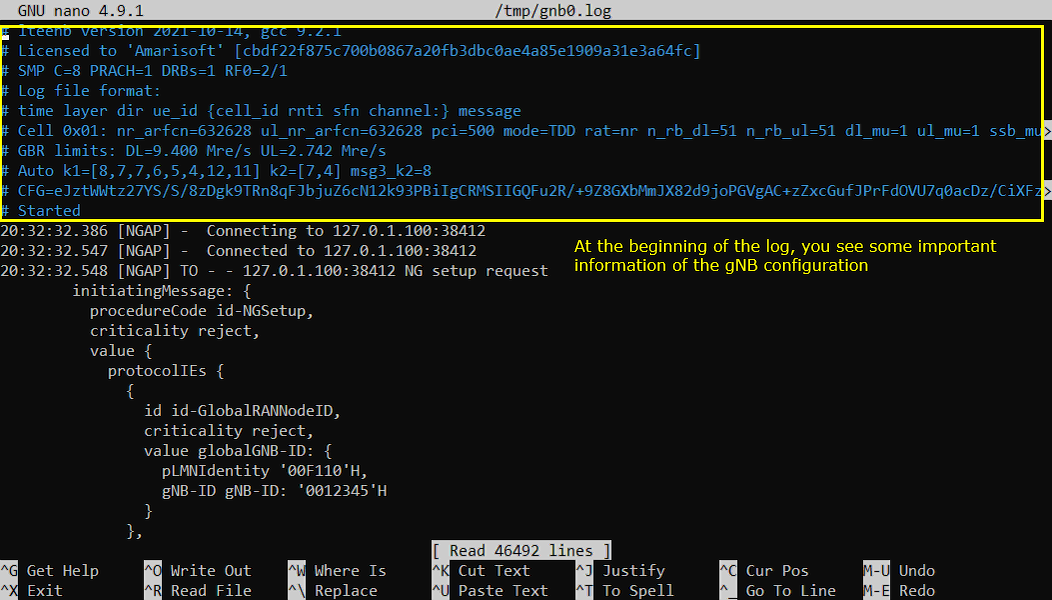
Open /tmp/gnb0.log using any text editor. I am using nano in this tutorial. you will see various high level information (meta data) at the beginning of the file. This is useful high level information. Check out this tutorial to the details on this meta data.
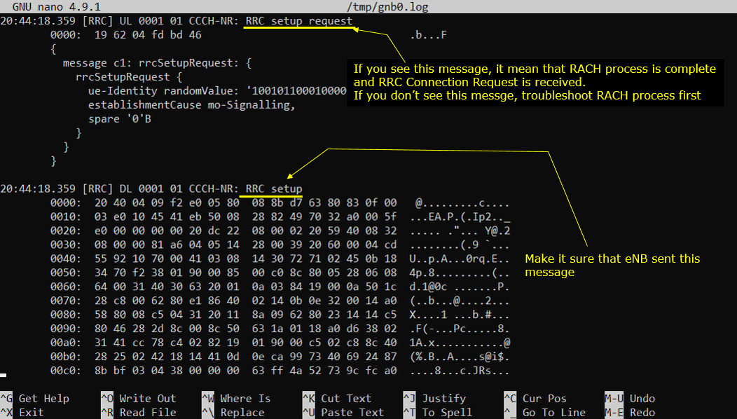
Now let's look into signaling message part of the log. The first thing you may want to check is 'RRC setupRequest' and 'RRC Setup'. If you get these message, it indicates that cell search and PRACH process is properly done on UE side and UE initiates RRC Setup.
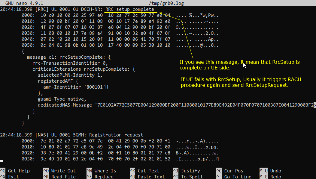
Next step you need to check is to see whether the eNB recieves RRC Setup Complete or not. If you see this message, it mean that RrcSetup is completed on UE side. If UE fails with RrcSetup, it usually triggers RACH procedure again and send Rrc Request.
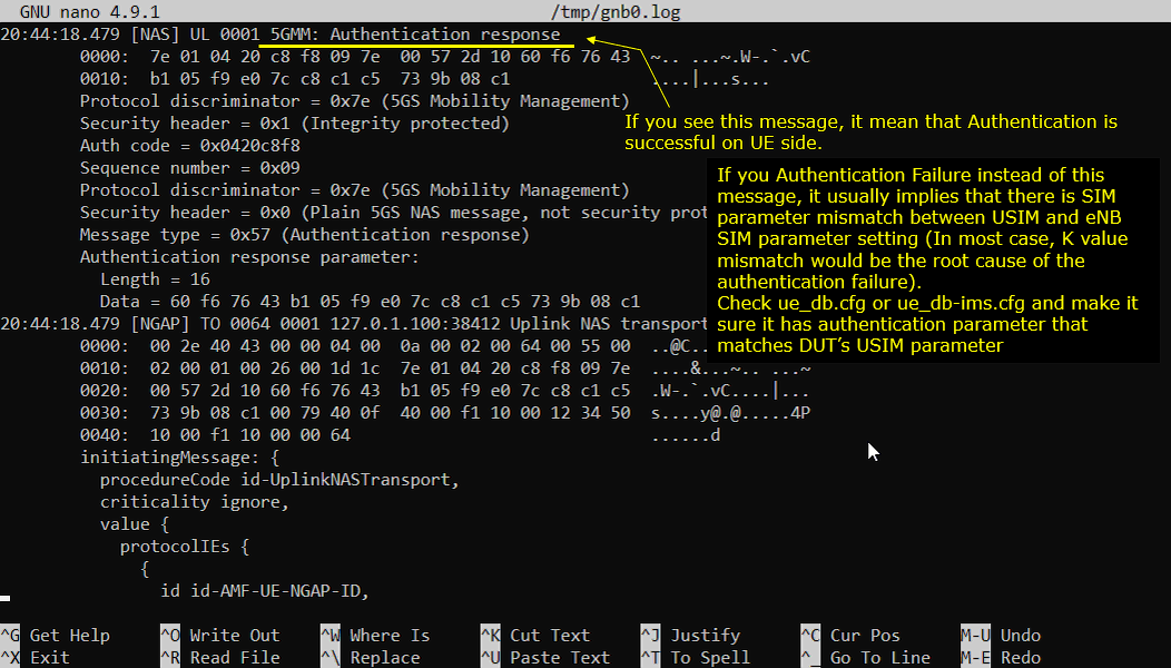
Once RRC Setup Procedure is complete, eNB initiate the Authentication process. If the authentication is confirmed on UE side, UE send Authentication Response message. If you see the Authentication Failure instead of Authentication Response, it usually implies that there is SIM parameter mismatch between USIM and eNB SIM parameter setting. In most case, K value mismatch would be the culprit of the failure. Check ue_db.cfg or ue_db-ims.cfg and make it sure it has authentication parameter that matches DUT's USIM parameter.
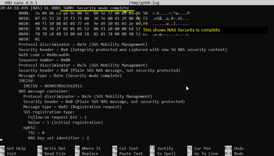
Once Authentication process is complete, gNB/5G Corestarts Security checkup. There are two different level of security checkup. The first one is NAS Security and the second one is RRC Security.
If you see GMM:Security mode complete message recieved, it indicates that NAS Security is complete.
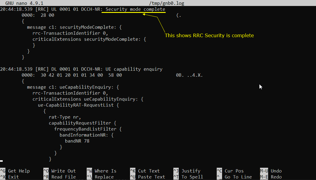
If you see DCCH-NR:Security mode complete message recieved, it indicates that RRCSecurity is complete.
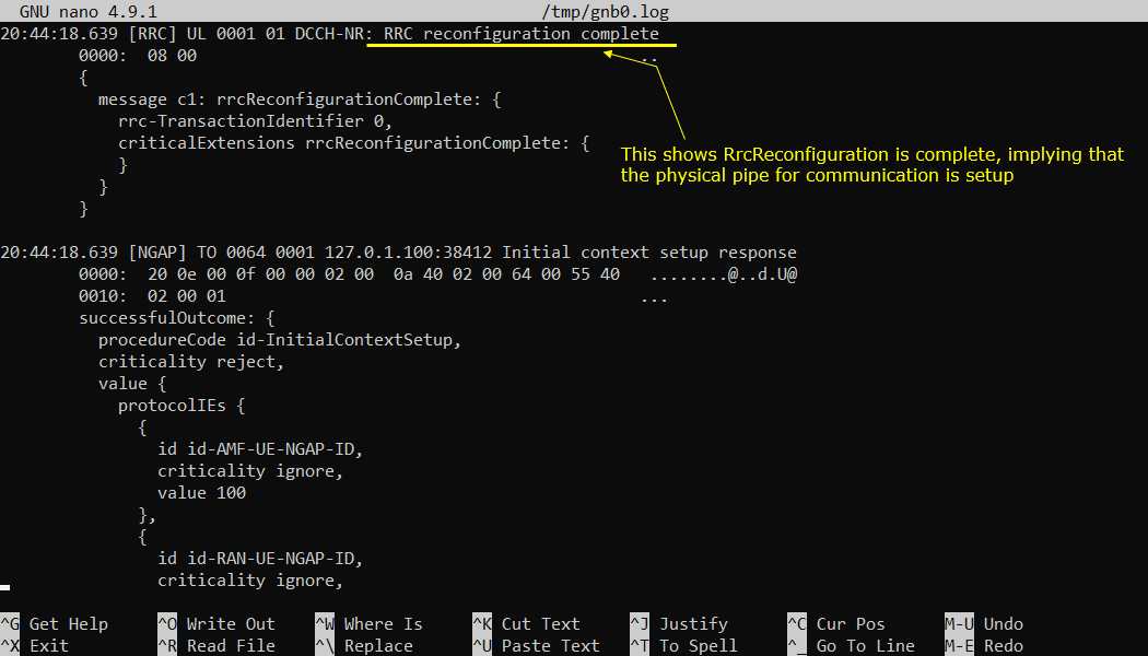
Once Authentication and Security checkup is done, eNB initiate RRC Reconfiguration. If the Rrc Reconfiguration is properly processed on UE side, UE send RRC Reconfiguration Complete.
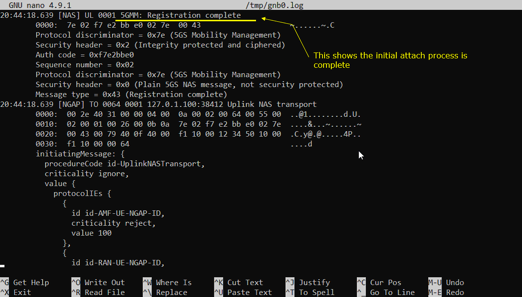
Once all the required RRC and NASProcedure for initial registration is complete, UE is supposed to send 5GMM:Registration completemessage.
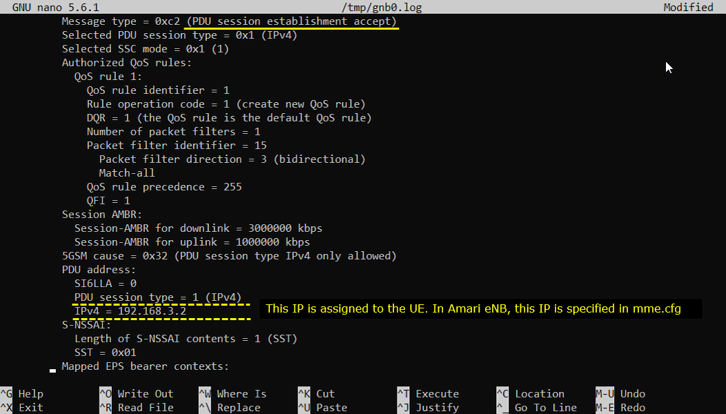
Once all the initial registration is complete, UE is supposed toinitiate PDU Sesttion Establishment. Network is supposed to send PDU Session establishment accept message when the request from UE is acceptable. One of the important information you would check in this message is IP address. This IP address is the one assigned to the UE.
Another important imformation carried by PDU Session establishment accept message is DNS address.
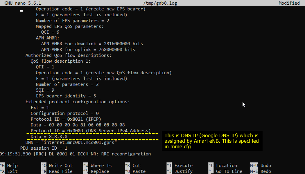
Once the entire registration is complete and UE IP and DNS IP is notified to UE, now UE is ready for data communication.
RRC / NAS Signaling
: This section is to show you the overall structure of important Rrc messages and Information IE (IE) that are related to this tutorial. It is not intended to describe the details on every RRC/NAS Information elements. With the overall structure and key IEs shown here, it hope it would be easier / clearer to go through the sample log provided in this tutorial or any logs that you captured from your own test setup or live network.
SIB1
: This is the SIB1message sent by gNB to configure NR SA. (
{
message c1: systemInformationBlockType1: {
cellSelectionInfo {
...
},
cellAccessRelatedInfo {
plmn-IdentityList {
...
},
connEstFailureControl {
...
},
servingCellConfigCommon {
downlinkConfigCommon {
frequencyInfoDL {
frequencyBandList {
{
freqBandIndicatorNR 78
}
},
offsetToPointA 24,
scs-SpecificCarrierList {
{
offsetToCarrier 0,
subcarrierSpacing kHz30,
carrierBandwidth 51
}
}
},
initialDownlinkBWP {
genericParameters {
locationAndBandwidth 13750,
subcarrierSpacing kHz30
},
pdcch-ConfigCommon setup: {
...
},
pdsch-ConfigCommon setup: {
...
},
bcch-Config {
...
},
pcch-Config {
...
}
},
uplinkConfigCommon {
frequencyInfoUL {
scs-SpecificCarrierList {
{
offsetToCarrier 0,
subcarrierSpacing kHz30,
carrierBandwidth 51
}
},
p-Max 10
},
initialUplinkBWP {
genericParameters {
locationAndBandwidth 13750,
subcarrierSpacing kHz30
},
rach-ConfigCommon setup: {
...
},
pusch-ConfigCommon setup: {
...
},
pucch-ConfigCommon setup: {
...
}
},
timeAlignmentTimerCommon infinity
},
ssb-PositionsInBurst {
inOneGroup '80'H
},
ssb-PeriodicityServingCell ms20,
tdd-UL-DL-ConfigurationCommon {
...
},
ss-PBCH-BlockPower -28
},
ue-TimersAndConstants {
...
}
}
}
RrcSetup
: This is the RrcSetupmessage sent by gNB to configure NR SA. (
message c1: rrcSetup: {
rrc-TransactionIdentifier 0,
criticalExtensions rrcSetup: {
radioBearerConfig {
...
},
masterCellGroup {
cellGroupId 0,
rlc-BearerToAddModList {
...
},
mac-CellGroupConfig {
...
},
physicalCellGroupConfig {
...
},
spCellConfig {
spCellConfigDedicated {
initialDownlinkBWP {
pdcch-Config setup: {
...
},
pdsch-Config setup: {
...
}
},
firstActiveDownlinkBWP-Id 0,
uplinkConfig {
initialUplinkBWP {
pucch-Config setup: {
...
},
pusch-Config setup: {
...
},
srs-Config setup: {
...
}
},
firstActiveUplinkBWP-Id 0,
pusch-ServingCellConfig setup: {
}
},
pdcch-ServingCellConfig setup: {
},
pdsch-ServingCellConfig setup: {
nrofHARQ-ProcessesForPDSCH n16
},
csi-MeasConfig setup: {
...
}
},
Registration Request
: Following is an example of registration request message from UE (
Protocol discriminator = 0x7e (5GS Mobility Management)
Security header = 0x1 (Integrity protected)
Auth code = 0x4295c610
Sequence number = 0x2e
Protocol discriminator = 0x7e (5GS Mobility Management)
Security header = 0x0 (Plain 5GS NAS message, not security protected)
Message type = 0x41 (Registration request)
5GS registration type:
Follow-on request bit = 1
Value = 1 (initial registration)
ngKSI:
...
5GS mobile identity:
5G-GUTI
...
UE security capability:
...
NAS message container:
Protocol discriminator = 0x7e (5GS Mobility Management)
Security header = 0x0 (Plain 5GS NAS message, not security protected)
Message type = 0x41 (Registration request)
5GS registration type:
Follow-on request bit = 1
Value = 1 (initial registration)
ngKSI:
..
5GS mobile identity:
5G-GUTI
...
5GMM capability:
...
UE security capability:
...
Requested NSSAI:
...
Last visited registered TAI:
...
S1 UE network capability:
...
UE's usage setting = 0x01 (Data centric)
LADN indication:
...
Network slicing indication = 0x00 (DCNI=0, NSSCI=0)
5GS update type = 0x01 (EPS-PNB-CIoT=no additional information, 5GS-PNB-CIoT=no additional information, NG-RAN-RCU=0, SMS requested=1)
Registration Accept
: Following is an example of registration acceptmessage from UE (
Protocol discriminator = 0x7e (5GS Mobility Management)
Security header = 0x2 (Integrity protected and ciphered)
Auth code = 0xc93c7d52
Sequence number = 0x02
Protocol discriminator = 0x7e (5GS Mobility Management)
Security header = 0x0 (Plain 5GS NAS message, not security protected)
Message type = 0x42 (Registration accept)
5GS registration result = 0x09 (Emergency registered=0, NSSAA to be performed=0, SMS allowed=1, 3GPP access)
5G-GUTI:
...
TAI list:
...
Allowed NSSAI:
...
5GS network feature support:
...
T3512 value:
...
Emergency number list:
...
PDU Session Establishment Request
: Following is an example of PDU session establishment requestmessage from UE (
Protocol discriminator = 0x2e (5GS Session Management)
PDU session identity = 1
Procedure transaction identity = 85
Message type = 0xc1 (PDU session establishment request)
Integrity protection maximum data data:
...
PDU session type = 0x3 (IPv4v6)
5GSM capability:
...
Extended protocol configuration options:
Ext = 1
Configuration protocol = 0
Protocol ID = 0xc223 (CHAP)
Data = 01 00 00 16 10 8c bb 1d 1d 8c bb 1d 1d 8c bb 1d 1d 8c bb 1d 1d 2a
Protocol ID = 0xc223 (CHAP)
Data = 02 00 00 16 10 c6 00 c0 d1 3b de b9 d7 0b 68 d9 33 26 ec fe fb 2a
Protocol ID = 0x8021 (IPCP)
Data = 01 00 00 10 81 06 00 00 00 00 83 06 00 00 00 00
Protocol ID = 0x000d (DNS Server IPv4 Address Request)
Data =
Protocol ID = 0x0003 (DNS Server IPv6 Address Request)
Data =
Protocol ID = 0x000a (IP address allocation via NAS signalling)
Data =
Protocol ID = 0x0005 (MS Support of Network Requested Bearer Control indicator)
Data =
Protocol ID = 0x0010 (IPv4 Link MTU Request)
Data =
Protocol ID = 0x0011 (MS support of Local address in TFT indicator)
Data =
Protocol ID = 0x0023 (QoS rules with the length of two octets support indicator)
Data =
Protocol ID = 0x0024 (QoS flow descriptions with the length of two octets support indicator)
Data =
PDU Session Establishment Accept
: Following is an example of PDU session establishment requestmessage from UE (
Protocol discriminator = 0x2e (5GS Session Management)
PDU session identity = 1
Procedure transaction identity = 85
Message type = 0xc2 (PDU session establishment accept)
Selected PDU session type = 0x1 (IPv4)
Selected SSC mode = 0x1 (1)
Authorized QoS rules:
...
Session AMBR:
...
5GSM cause = 0x32 (PDU session type IPv4 only allowed)
PDU address:
SI6LLA = 0
PDU session type = 1 (IPv4)
IPv4 = 192.168.3.2
S-NSSAI:
Length of S-NSSAI contents = 1 (SST)
SST = 0x01
Mapped EPS bearer contexts:
...
Authorized QoS flow descriptions:
...
Extended protocol configuration options:
Ext = 1
Configuration protocol = 0
Protocol ID = 0x8021 (IPCP)
Data = 03 00 00 0a 81 06 08 08 08 08
Protocol ID = 0x000d (DNS Server IPv4 Address)
Data = 8.8.8.8
DNN = "internet.mnc001.mcc001.gprs"
Troubleshoot
: SA capable device is not as common as NSA capable device. Even when you get a device (UE) that claims to support SA. You may see many cases that would not work (would not camp on) to callbox. Check out the items below to figure out the root cause of the failure.
SA Camp On Failure
: If your UE does not camp on to SA (meaning that UE does not even trigger PRACH to SA Cell), you may check on followings.
Check Point 1 : Try with NSA
: Try first with NSA. If it does not work even with NSA, it is highly likely that your UE does not support NR at all. (
Check Point 2: Check out UE capability information
: Collect UE capability Information from LTE log or NSA log and check if NR SA capability is supported. You may check with IE N1mode and irat-ParametersNR
UE network capability:
0xf0 (EEA0=1, 128-EEA1=1, 128-EEA2=1, 128-EEA3=1, EEA4=0, EEA5=0, EEA6=0, EEA7=0)
0x70 (EIA0=0, 128-EIA1=1, 128-EIA2=1, 128-EIA3=1, EIA4=0, EIA5=0, EIA6=0, EIA7=0)
0xc0 (UEA0=1, UEA1=1, UEA2=0, UEA3=0, UEA4=0, UEA5=0, UEA6=0, UEA7=0)
0x40 (UCS2=0, UIA1=1, UIA2=0, UIA3=0, UIA4=0, UIA5=0, UIA6=0, UIA7=0)
0x19 (ProSe-dd=0, ProSe=0, H.245-ASH=0, ACC-CSFB=1, LPP=1, LCS=0, 1xSRVCC=0, NF=1)
0x80 (ePCO=1, HC-CP CIoT=0, ERw/oPDN=0, S1-U data=0, UP CIoT=0, CP CIoT=0, ProSe-relay=0, ProSe-dc=0)
0xb0 (15 bearers=1, SGC=0,
irat-ParametersNR-v1540 {
eutra-EPC-HO-ToNR-TDD-FR1-r15 supported,
sa-NR-r15 supported,
{
bandNR-r15 41
},
{
bandNR-r15 78
}
}
Check Point 3: the bandwidth and SCS
: Check out the bandwidth and SCS(Subcarrier Spacing) that are supported by the UE and see if you configured them accordingly in your configuration file. Following is an example.
channelBWs-DL-v1530 fr1: {
scs-15kHz '0000000000'B,
scs-30kHz '0000001111'B, => support 40,50,60,80 and 100 (max BW)
scs-60kHz '0000000000'B
},
channelBWs-UL-v1530 fr1: {
scs-15kHz '0000000000'B,
scs-30kHz '0000001111'B, => support 40,50,60,80 and 100 (max BW)
scs-60kHz '0000000000'B
}
Check Point 4: check if Any Well Known UE Issue
: Based on our experience, some wellknown commercial UEs disable NR SA when it is with Test USIM (Not the Network Operator UE). I would suggest you to check about this possibility before you purchase the UE if it is only for testing.