
Out of the Box Test - Internet Access
The purpose of this tutorial is to show you how to get access to internet from the UE through Amari Callbox. It is assumed that you don't have any previous experience with Amari callbox.
Personally I think the Internet Access is one of the best feature for Amarisoft Callbox (eNB/gNB). Of course, most of the other test equipment allow you to get access to Internet, but not as easy as you do with Amarisoft Callbox. If you get your callbox to any eithernet port that has access to Internet, by default your UE would get access to internet by default.
By detault, as soon as your UE complete the initial attach, your UE would get a local IP address and DNS address (google DNS by default). With those default IP address and DNS, your UE would get access to internet and perform any task/test over the internet, for example, browsing, YouTube, File Download, Speedtest etc. If you have any network connection to Internet on callbox (whether it is wired LAN or WLAN), it gets automatically configured as the default Gateway for all the UE IP address you configured and the UE would get access to Internet.
Even though the internet access setting is automatically configured by default, you can still customize it depending on your test requirement. For example, you may configure your own UE IP address range, use your own DNS server, or modify the routing behavior if your test setup requires a specific network configuration. The overall data path and main components used for UE internet access are illustrated below.
Before the UE completes the initial attach and PDN/PDU session establishment, the UE does not have an IP address yet. At this stage, the eNB/gNB side handles the radio protocol stack such as RRC, PDCP, RLC, MAC, and PHY, and it is connected to the RF side either through SDR or RRH/CPRI depending on the hardware configuration. The core network side already has tun interfaces such as tun0, tun1, tun2, and tun3, but these interfaces are not yet associated with an active UE data session.
After the UE completes the initial attach with PDN/PDU establishment in LTE, or PDU session establishment in NR, the core network assigns an IP address to the UE. In this example, the UE receives an IP address such as 192.168.2.2, and the corresponding tun interface on the core network side uses an address such as 192.168.2.1. Other tun interfaces may use different subnets, for example 192.168.3.1, 192.168.4.1, and 192.168.5.1, depending on how many UE networks or APN/DNN configurations are used.
Once the UE IP address is assigned, user-plane traffic can flow between the UE and the core network through the radio stack and GTP-U path. From the core network, the traffic is forwarded to the default gateway of the Callbox, and then it can reach external internet services. DNS resolution can be handled by the configured DNS server, such as Google DNS 8.8.8.8 in this example. As a result, normal internet applications on the UE, such as browsing, video streaming, file download, or speed test, can work through the Callbox internet connection.
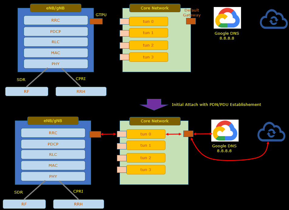
Table of Contents
- Out of the Box Test - Internet Access
- Introduction
- Summary of the Tutorial
- Test Setup
- Configuration
- Check Up before trying UE connection
- Check Up Network Interfaces
- Check Up Routing Table
- Check Up IP table/NAT Table
- Check Up IP forwarding
- Check Up Connectivity between Callbox and External World
- Check up before Start
- Initial Attach
- Trying Ping from UE over Internet
- Trying Internet from UE
- Analyzing Traffic with WebGUI
- Analyzing IP Traffic
- Tips
Introduction
Amarisoft Callbox is a highly flexible and powerful cellular network emulator that enables users to establish and test end-to-end LTE and 5G NR connections with commercial User Equipment (UE) in a controlled lab environment. Designed for rapid prototyping, interoperability testing, and feature validation, the Callbox integrates both radio access (eNB/gNB) and core network (EPC/5GC) functions within a single platform. This consolidated architecture simplifies network deployment, allowing UEs to connect over-the-air to the Callbox, perform registration, authentication, and session establishment, and subsequently gain access to the internet through the callbox’s integrated Packet Data Network Gateway (PGW/UPF). The Amari Callbox stands out for its ease of configuration and automation, providing a seamless mechanism for assigning IP addresses and DNS settings to UEs, and efficiently routing traffic between the cellular domain and external IP networks via standard interfaces such as Ethernet or WLAN. As a result, it is widely used for device validation, application testing, and protocol analysis, supporting use cases ranging from basic connectivity checks to advanced performance benchmarking. This tutorial focuses on enabling internet access for UEs through the Amari Callbox, detailing the default behavior and customizable options for network configuration, and outlining the essential components and data paths involved in delivering internet connectivity within a lab setup. Understanding these principles is crucial for engineers and testers aiming to leverage the full potential of the Callbox for end-to-end data session testing and real-world application scenarios.
-
Context and Background
- Amarisoft Callbox serves as an all-in-one testbed combining radio access and core network functionalities, facilitating comprehensive LTE and 5G testing with real UEs.
- Internet access through the Callbox is a core feature, enabling UEs to connect seamlessly to external networks for a wide range of data services and application testing.
- The system automatically assigns IP addresses and DNS information to UEs upon successful attachment, routing all user data traffic through configurable interfaces that bridge the cellular and IP domains.
-
Relevance and Importance
- Internet connectivity is essential for validating device interoperability, application performance, and user experience in simulated real-world conditions.
- Amarisoft Callbox’s streamlined configuration process provides a significant advantage over conventional test equipment, minimizing setup complexity and accelerating test cycles.
- Customizable network settings allow for flexible testing scenarios, supporting both default and user-defined IP/DNS configurations, which is crucial for advanced use cases and troubleshooting.
-
What You Will Learn
- How to establish internet access for UEs using the Amari Callbox, leveraging its default and customizable network configuration features.
- The architectural flow of data from UE attachment, IP assignment, and DNS resolution to the actual routing of traffic between the cellular and IP networks.
- Best practices for configuring and verifying internet connectivity, including managing tun interfaces and understanding their relationship to PDN/PDU sessions.
-
Prerequisite Knowledge
- Basic familiarity with cellular network concepts (LTE, 5G, eNB/gNB, EPC/5GC) is helpful but not required, as the tutorial is designed for newcomers.
- General understanding of IP networking and Ethernet/WLAN connectivity will aid in comprehending the routing and interface configuration steps.
- No prior experience with Amarisoft Callbox is assumed; all necessary foundational concepts and procedures are covered.
-
Scope and Alignment
- The tutorial is focused on providing clear, step-by-step guidance for enabling and validating internet access on UEs via the Amari Callbox in a lab environment.
- Architectural overviews, high-level process flows, and practical configuration tips are emphasized to ensure a comprehensive and accessible learning experience.
Summary of the Tutorial
This tutorial provides a comprehensive guide for performing out-of-the-box internet connectivity tests using Amarisoft Callbox, including setup, configuration, verification, and troubleshooting methodologies. The procedures are structured to ensure successful IP connectivity between the User Equipment (UE) and the external internet through the Callbox.
-
Test Setup
- Use the default configuration file and SIM card provided with the system for out-of-the-box testing.
- Multiple options for connecting the Callbox to the Internet are discussed; Case 4 is used in this tutorial.
- For WiFi connectivity (Cases 2 and 3), Linux command-line utilities such as
nmcliare recommended for managing WiFi networks, as there is no GUI.
-
Configuration Steps
- Ensure the eNB and core network configuration files (
enb.cfg,mme.cfg,ims.cfg) are correctly linked to their respective default files. - Symbolic links are set up using
ln -sfcommands if needed, ensuring the software uses the intended configuration.
- Ensure the eNB and core network configuration files (
-
Pre-Connection System Checks
-
Check Network Interfaces:
- Verify that the internet-connected interface (e.g., eno1) and tun interfaces (tun0,1,2,3) are up and assigned as expected. This requires the LTE service to be running.
-
Check Routing Table:
- Ensure the routing table includes a valid gateway and that tun interfaces are routed correctly through the gateway interface.
- Test gateway connectivity using
ping. - Confirm no IP conflicts between gateway and tun interface addresses.
-
Check IPtable/NAT Table:
- Confirm proper NAT masquerading rules using
iptables -t nat -L -v -n. - If missing, run initialization scripts such as
./lte_init.shto set up NAT.
- Confirm proper NAT masquerading rules using
-
Check IP Forwarding:
- Verify and enable IP forwarding using
sysctl net.ipv4.ip_forwardandsysctl -w net.ipv4.ip_forward=1if required.
- Verify and enable IP forwarding using
-
Check External Connectivity:
- Validate internet access by pinging an external IP (e.g., 8.8.8.8) and domain (e.g., www.google.com) from the Callbox.
-
Check Network Interfaces:
-
UE Pre-Test Preparation
- Disable WiFi and enable Airplane mode on the UE before the test to ensure cellular data is prioritized.
-
Initial Attach Procedure
- Turn off Airplane mode (or power on UE) to initiate attach to the Callbox.
- Confirm UE connection and ensure that the UE is assigned an IP address.
- Ping from Callbox to UE to verify link-layer and IP connectivity.
-
Ping and Internet Access from UE
- Install a ping application on the UE and perform ping tests to both IP addresses and domain names to confirm DNS functionality and external reachability.
- Test real internet services from the UE such as web browsing, video streaming (YouTube), and network speed tests to ensure end-to-end connectivity and throughput.
-
Traffic Analysis and Troubleshooting
-
WebGUI Analysis (Optional):
- Use the WebGUI for throughput monitoring and slot-level statistics.
- Check retransmission statistics to assess radio link quality.
-
IP Traffic Analysis:
- Capture IP traffic at multiple points using
tcpdumpor Wireshark for in-depth troubleshooting. - For Wireshark, use remote GUI sessions (
ssh -X) for live packet analysis on the Callbox interfaces. - Perform stepwise ping tests and inspect packet flows through different interfaces (e.g., tun, gateway).
- Use WebGUI to monitor GTPU traffic and identify broken links in the data path by comparing logs between Wireshark and WebGUI.
- Capture IP traffic at multiple points using
-
WebGUI Analysis (Optional):
-
Best Practices and Tips
- Understand that WiFi adapters and range extenders may limit throughput; use appropriate hardware for high-speed tests.
- Avoid subnet conflicts between WiFi networks and Callbox/UEsim interfaces by configuring unique subnets.
- Ensure WiFi Access Points and Range Extenders are not placed too close to avoid interference.
The tutorial emphasizes a systematic approach to verification at every stage, ensuring all network components are properly configured and operational before initiating UE data tests. Troubleshooting methodologies include both command-line and GUI-based tools for comprehensive diagnostics.
Test Setup
Test setup for this tutorial is as shown below.
- Since this test is for Out of the box testing, I used the default configuration(cfg) file without changing anything in it
- SIM Card used in this tutorial is the one delivered with the system as it is.
- If you want to change the configuration, The tutorial Configuration Guide would help
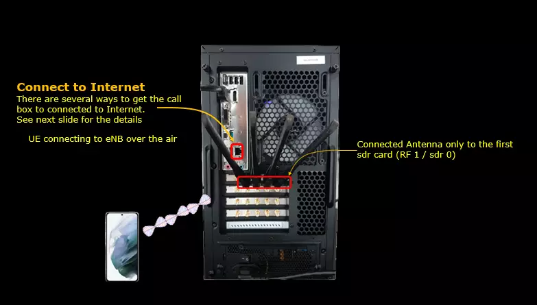
In this setup, the UE connects to the eNB/gNB over the air. The antenna is connected only to the first SDR card, RF 1 / sdr 0, and this is enough for the basic internet access test shown here. The Callbox itself also needs to be connected to the internet, because UE traffic will eventually be routed through the Callbox default gateway toward the external network. There are several ways to connect the Callbox to the internet, and the following section explains those options in more detail.
If you want to modify the default behavior, for example changing IP address assignment, DNS setting, APN/DNN, or routing configuration, refer to the Configuration Guide. For this basic test, however, no manual configuration change is required.
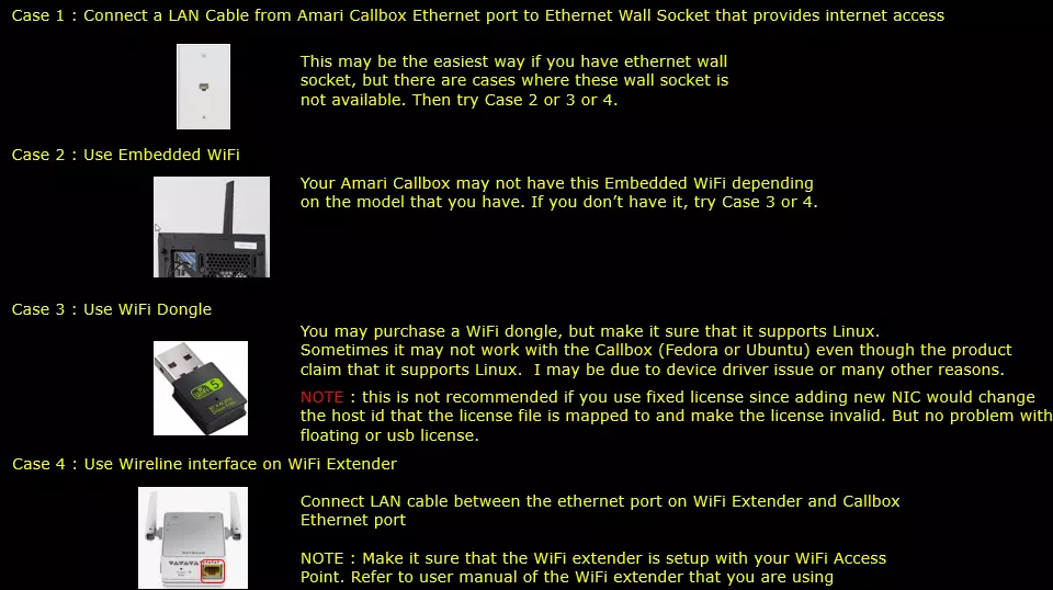
There are several ways to provide internet access to the Callbox. In this tutorial, Case 4 is used, but the basic idea is the same for all cases: the Callbox must first have its own working internet connection, and then the UE traffic can be routed through that connection after attach and PDN/PDU session establishment.
Case 1 is to connect a LAN cable directly from the Amarisoft Callbox Ethernet port to an Ethernet wall socket that provides internet access. This is usually the easiest method if a wired Ethernet port is available in the lab. However, in many test environments, an Ethernet wall socket may not be available near the Callbox, or the available Ethernet network may have access restrictions. In that case, one of the other methods can be used.
Case 2 is to use the embedded WiFi interface of the Callbox. Some Amarisoft Callbox models may have built-in WiFi, so the Callbox can connect directly to an existing WiFi access point. However, this option depends on the Callbox model, and not every system has embedded WiFi. If your Callbox does not have this interface, use Case 3 or Case 4 instead.
Case 3 is to use a USB WiFi dongle. This can be useful when wired Ethernet is not available and the Callbox does not have embedded WiFi. However, the WiFi dongle must support Linux, and even if the product claims Linux support, it may still fail depending on the driver, kernel version, or distribution environment used by the Callbox. It is also not recommended to use a fixed license together with a WiFi dongle because the dongle may create a new NIC and change the host ID used by the license. This can make the fixed license invalid. Floating license or USB license is safer in this case.
Case 4 is to use the wired Ethernet interface of a WiFi extender. In this method, the WiFi extender connects to the existing WiFi access point, and a LAN cable is connected between the Ethernet port of the WiFi extender and the Ethernet port of the Callbox. From the Callbox point of view, this behaves like a normal wired Ethernet connection, so it is often simpler and more reliable than using a USB WiFi dongle. Before using this method, make sure the WiFi extender is already configured correctly with your WiFi access point according to the user manual of the extender.
If you decide to use Case 2 or Case 3, the following tips may be helpful.
The Amarisoft Callbox usually runs Linux such as Fedora or Ubuntu in command-line mode, not in a desktop GUI environment. Because of this, enabling WiFi, scanning available WiFi networks, and connecting to a WiFi access point may not be as straightforward as it is on a normal desktop PC.
The following nmcli commands are commonly used to check and configure WiFi connectivity from the command line. nmcli dev status shows the available network interfaces and their current connection status. nmcli radio wifi checks whether WiFi is enabled or disabled. nmcli device wifi rescan forces the system to scan nearby WiFi access points again. nmcli dev wifi list shows the detected WiFi networks. nmcli dev wifi connect network-ssid password network-password connects the Callbox to the selected WiFi network using the specified SSID and password.
These commands are only a basic starting point. The exact behavior may depend on the Linux distribution, WiFi chipset, driver, and network policy used in your lab, so you may need to check the detailed nmcli usage or your Linux network configuration if the connection does not work immediately.
# nmcli dev status
# nmcli radio wifi
# nmcli device wifi rescan
# nmcli dev wifi list
# nmcli dev wifi connect network-ssid password "network-password"
Configuration
You can use any configuration that will assign at least one IP to UE with internet apn. If you just want to try with what I have used in this tutorial, you can do as follows.
Go to the directory /root/enb/config and make a symbolic link as follows. (NOTE : If you are doing the test right out of the box you may not need to do this since this is the default configuration of Amari Callbox, but it is no harm to do this again).

Now you should see the enb.cfg file linked to enb.default.cfg as follows. Here you see enb.cfg is symolically linked to enb.default.cfg. When you run callbox software, eNB and gNB is using the configuration file that is linked to enb.cfg

Now go to the directory /root/mme/config. You should see the configuration files as below. Here you see ims.cfg is symolically linked to ims.default.cfg and mme.cfg is symbolically linked to mme-ims.cfg. When you run callbox software, 4G core and 5G core are using the configuration file that is linked to mme.cfg and IMS server is using the configuration file that is linked to ims.cfg
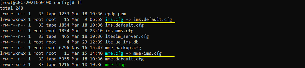
If ims.cfg and mme.cfg is not linked to the files as shown above, you may run following commands to make proper link.
"ln -sf mme-ims.cfg mme.cfg" mean 'link mme-ims.cfg to mme.cfg' and "ln -sf ims.default.cfg ims.cfg" mean "link ims.default.cfg to ims.cfg"

Check Up before trying UE connection
Before you trying internet connection with UE, you need to check several basic things shown in this section and make it sure everything works as shown here, otherwise Internet connection from UE may not work.
Check Up Network Interfaces
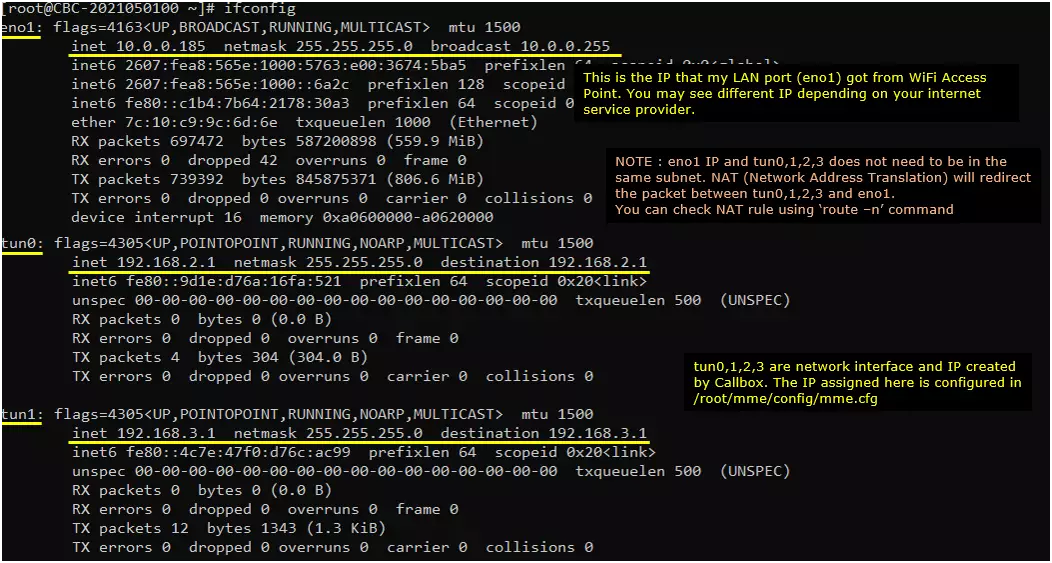
Make it sure that the network interface with internet connectivity is up and tun0,1,2,3 are up. [eno1] is the Network interface that is connected over the WiFi network in my test setup. You may see different name in your setup. The interface tun0,1,2,3 are network interface crated by Callbox. The IP assigned to these interfaces are configured in /root/mme/config/mme.cfg
In this example, eno1 is the interface connected to the external network through the WiFi extender, and it received the IP address 10.0.0.185 from the WiFi access point. The actual interface name and IP address may be different depending on your Callbox model, Linux configuration, and local network.
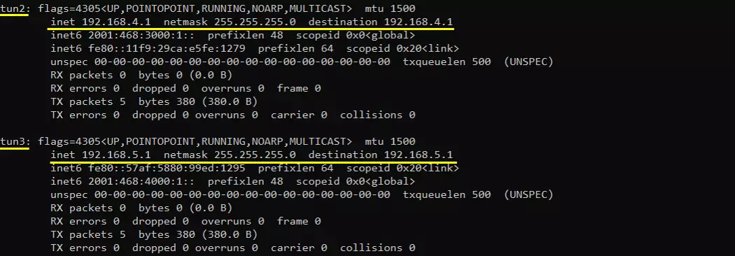
The tun0, tun1, tun2, and tun3 interfaces are created by the Callbox when the LTE service is running. In this example, tun0 is configured with 192.168.2.1, tun1 with 192.168.3.1, tun2 with 192.168.4.1, and tun3 with 192.168.5.1. These IP addresses are configured in /root/mme/config/mme.cfg and are used as the gateway-side addresses for UE IP subnets. For example, when a UE is assigned an address in the 192.168.2.x range, tun0 with 192.168.2.1 works as the corresponding core-network-side interface.
To see these tun interfaces, the LTE service should be running, for example by running service lte restart. However, a UE does not need to be attached just to check whether the tun interfaces exist. The tun interfaces can appear as soon as the Callbox service starts and creates the configured UE network interfaces.
The external interface such as eno1 and the tun interfaces do not need to be in the same subnet. In this example, eno1 is in the 10.0.0.x subnet, while tun0 to tun3 are in the 192.168.x.x subnets. Traffic between these interfaces is forwarded by routing and NAT, so UE packets can be translated and sent out through the external interface toward the internet. If you need to check the routing or NAT behavior in more detail, you can use commands such as route -n or inspect the NAT rules on the Callbox.
Check Up Routing Table
Check up the routing table on CallBox PC. It would usually be as follows.
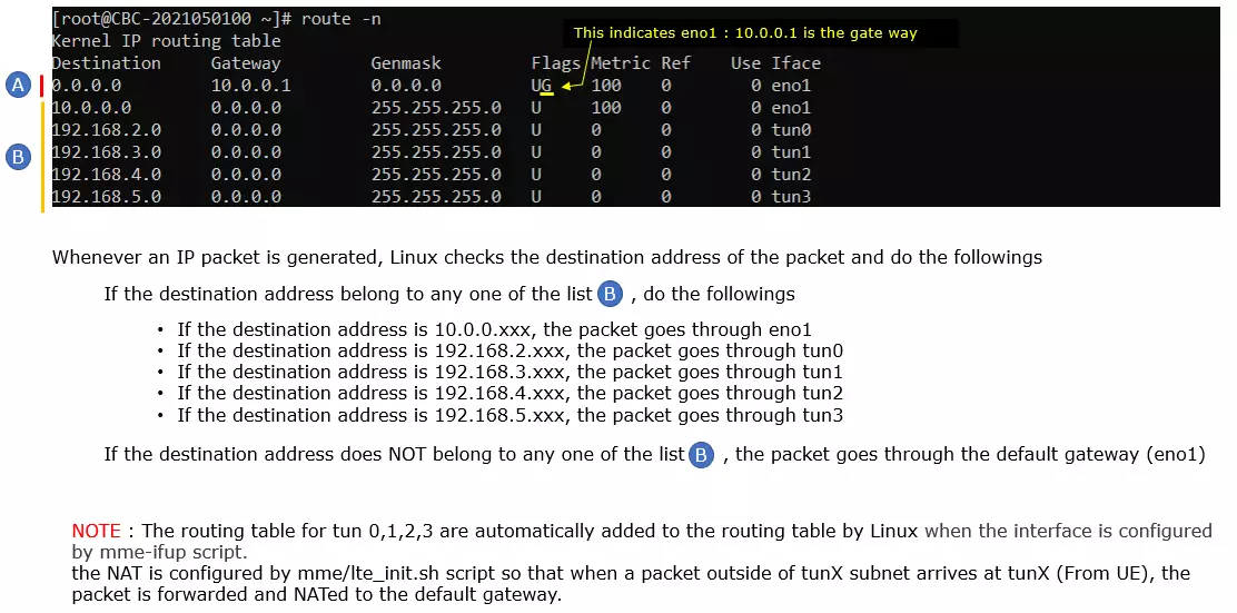
A typical routing table is shown below. The gateway interface name may be different depending on your system configuration, but you should see the tun0, tun1, tun2, and tun3 routes if the LTE service is running correctly. In this example, eno1 is used as the external network interface, and the default gateway is 10.0.0.1 through eno1. This means that traffic whose destination is outside the local Callbox subnets will be forwarded toward 10.0.0.1 via eno1.
At least one default gateway route should be present. If there is no default gateway, the UE may still be able to exchange IP packets with the Callbox, for example pinging the tun interface address such as 192.168.2.1, but it will not be able to reach the external internet. The default route is the path used when the destination IP address does not match any more specific route in the routing table.
In this example, the routing table has specific routes for 10.0.0.0/24 through eno1, 192.168.2.0/24 through tun0, 192.168.3.0/24 through tun1, 192.168.4.0/24 through tun2, and 192.168.5.0/24 through tun3. When Linux sends an IP packet, it first checks whether the destination address belongs to one of these known subnets. If the destination is 10.0.0.x, the packet goes through eno1. If the destination is 192.168.2.x, it goes through tun0. If the destination is 192.168.3.x, it goes through tun1. If the destination is 192.168.4.x, it goes through tun2. If the destination is 192.168.5.x, it goes through tun3.
If the destination address does not belong to any of these listed subnets, the packet is sent through the default gateway. For example, traffic toward public internet addresses is not part of the 10.0.0.x or 192.168.x.x local subnets, so it is forwarded to 10.0.0.1 through eno1. The routes for tun0, tun1, tun2, and tun3 are automatically added by Linux when those interfaces are created and configured by the mme-ifup script. NAT is configured by the mme/lte_init.sh script so that when UE traffic arrives from a tun interface and needs to go outside the UE subnet, the packet is forwarded and translated toward the default gateway.
The line default via 10.0.0.1 dev eno1 proto dhcp metric 100 indicates that the Callbox sends packets to 10.0.0.1 through the eno1 interface when there is no more specific route for the destination. This means the default gateway IP address is 10.0.0.1, and the active external network interface is eno1.
The line 10.0.0.0/24 dev eno1 proto kernel scope link src 10.0.0.185 metric 100 indicates that eno1 belongs to the 10.0.0.x subnet and that the IP address assigned to eno1 is 10.0.0.185. This is the IP address that the Callbox received from the external network, for example from the WiFi access point or router through DHCP.
In short, this output shows that the default gateway IP is 10.0.0.1, the active network interface for internet access is eno1, and the Callbox IP address on that network is 10.0.0.185.
|
[root@CBC-2023010100 ~]# ip route default via 10.0.0.1 dev eno1 proto dhcp metric 100 10.0.0.0/24 dev eno1 proto kernel scope link src 10.0.0.185 metric 100 192.168.122.0/24 dev virbr0 proto kernel scope link src 192.168.122.1 linkdown 224.0.0.0/3 dev eno1 scope link |
What this indicates are
- Your default gateway IP is: 10.0.0.1
- Your active network interface is: eno1
- Your IP address is: 10.0.0.185
A quick way to check whether the default gateway is really reachable is to run a ping test from the Callbox. In this example, ping 10.0.0.1 is used because 10.0.0.1 is the default gateway shown by the routing table and ip route command.
If the ping response is received, it means the Callbox can reach the gateway through the external network interface. In this example, replies are received from 10.0.0.1 with normal ICMP sequence numbers, TTL values, and response times, so the basic connection between the Callbox and the gateway is working.
If the ping command hangs, or if it shows messages such as Destination Host Unreachable or Request timed out, there may be a routing issue, firewall issue, cable or WiFi extender issue, or a general network connectivity problem between the Callbox and the gateway.
Also make sure that the default gateway address does not collide with any of the tun interface addresses. For example, the default gateway should not be the same as tun0, tun1, tun2, or tun3. If the gateway address overlaps with a UE subnet or is the same as one of the tun interface IP addresses, Linux routing can become ambiguous and UE internet access may fail even if the Callbox service itself is running.
|
[root@CBC-2023010100 ~]# ping 10.0.0.1 PING 10.0.0.1 (10.0.0.1) 56(84) bytes of data. 64 bytes from 10.0.0.1: icmp_seq=1 ttl=64 time=7.49 ms 64 bytes from 10.0.0.1: icmp_seq=2 ttl=64 time=3.53 ms 64 bytes from 10.0.0.1: icmp_seq=3 ttl=64 time=5.88 ms 64 bytes from 10.0.0.1: icmp_seq=4 ttl=64 time=48.4 ms |
If it hangs or says Destination Host Unreachable or Request timed out, there may be a routing, firewall, or network issue.
Make it sure that your default gateway does not collide with any of your tun interface IP. Setting the default gateway address to be same as any of the tun interface ip address would cause various types of problems.
Check Up IP table/NAT Table
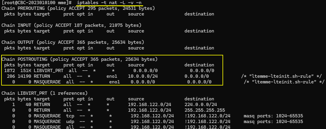
Especially when the UE needs to access an external network, make sure that the NAT table is configured properly on the Callbox. You can check the current NAT setting with the Linux command iptables -t nat -L -v -n. In the output, the most important part is the POSTROUTING chain because this is where packets are translated before they are sent out through the external network interface.
In this example, the POSTROUTING chain includes rules created by the Amarisoft LTE initialization script. The rule with source 10.0.0.0/24 and output interface eno1 is related to traffic going out through the external interface. The MASQUERADE rule on eno1 means that packets forwarded out through eno1 can be source-NATed so that they appear as packets coming from the Callbox external IP address. This is required because UE private IP addresses, such as 192.168.x.x, are not directly routable on the external network or internet.
The comments such as ltemme-lteinit.sh-rule indicate that these NAT rules were added by the Amarisoft initialization script. This is important because it confirms that the Callbox service has configured the expected forwarding/NAT behavior automatically. If this POSTROUTING MASQUERADE rule is missing, the UE may still be able to get an IP address and communicate with the Callbox tun interface, but packets going toward the external internet may not return correctly because the external network does not know how to route back to the UE private subnet.
In short, this check confirms that UE traffic arriving from the Callbox internal/tun side can be forwarded and translated toward the external interface eno1. Together with a valid default gateway and working routing table, this NAT rule is one of the key requirements for UE internet access through the Callbox.
- cd /root/mme
- ./lte_init.sh
- try 'iptables -t nat -L -v -n' and see if the table is set as expected
Check Up IP forwarding
Even if the routing table and NAT table are configured correctly, UE packets cannot pass through the Callbox toward the default gateway if IP forwarding is disabled. IP forwarding is the Linux function that allows the Callbox to behave as a router between different interfaces, for example between tun0 and eno1.
You can check the current IP forwarding setting with the command sysctl net.ipv4.ip_forward. If the output is net.ipv4.ip_forward = 1, IP forwarding is enabled. If the output is net.ipv4.ip_forward = 0, IP forwarding is disabled.
In this example, the output shows net.ipv4.ip_forward = 1, so the Callbox is allowed to forward IPv4 packets between interfaces. This is the expected setting for UE internet access, because UE traffic enters the Callbox through a tun interface and then needs to be forwarded toward the external network interface and default gateway.
If IP forwarding is disabled, you can enable it temporarily by running sysctl -w net.ipv4.ip_forward=1. This enables forwarding immediately, but depending on the Linux configuration, it may not remain enabled after reboot unless it is also configured persistently.

Check Up Connectivity between Callbox and External World
Before checking UE internet access, first make sure that the Callbox itself can reach an external server on the internet. In this example, the connectivity is checked by pinging 8.8.8.8.
The address 8.8.8.8 is Google DNS, and it is also commonly configured as the default DNS in mme.cfg. This is an important check because if the Callbox cannot reach 8.8.8.8, the UE will not be able to reach the internet through the Callbox either. In that case, the problem should be debugged at the Callbox network level first, before checking UE attach, UE IP address assignment, or application-level traffic.
In this example, ping 8.8.8.8 returns normal replies with ICMP sequence numbers, TTL values, and response times. This confirms that the Callbox has a working route to the external internet through its default gateway. If this ping fails, the likely cause is outside the Amarisoft radio/core configuration, such as LAN/WiFi connection, gateway setting, firewall policy, DHCP issue, or internet access restriction in the local network.

- Analyzing IP Traffic
- Check Up Network Interfaces
- Check Up Routing Table
- Check Up IP table/NAT Table
- Check Up IP forwarding
Next, check whether DNS resolution is working on the Callbox. The previous test with ping 8.8.8.8 checks basic IP connectivity to the external internet, but it does not confirm whether the Callbox can resolve a domain name. To check DNS, try pinging a URL such as www.google.com
In this example, ping www.google.com is resolved to a Google server address, and the Callbox receives normal ping replies. This confirms two things: first, DNS resolution is working because the domain name www.google.com was translated into an IP address, and second, the Callbox can reach that resolved address over the internet.
If ping 8.8.8.8 works but ping www.google.com fails, the internet path itself is probably working, but DNS configuration may be wrong or unreachable. In that case, check the DNS setting used by the Callbox, the DNS configured in mme.cfg, and the DNS information received from the external network.

Optionally, you can also check the IP address of a specific URL and then test connectivity using both the domain name and the resolved IP address. This helps you separate DNS-related problems from general IP connectivity problems.
In this example, nslookup www.google.com is used to query the DNS server. The output shows that the DNS server used by the Callbox is 64.71.255.204, and that www.google.com is resolved to addresses such as 142.251.41.68 for IPv4 and 2607:f8b0:400b:807::2004 for IPv6. The exact resolved address may be different depending on your location, DNS server, and Google server selection.
If ping to the resolved IP address works but ping to www.google.com does not work, the network path is probably working but DNS resolution has a problem. If both the resolved IP address and the domain name fail, the issue is more likely related to routing, gateway, firewall, or general external connectivity from the Callbox.

Check up before Start
Before trying to access the internet from the UE or DUT, it is better to check a few basic UE-side settings first.
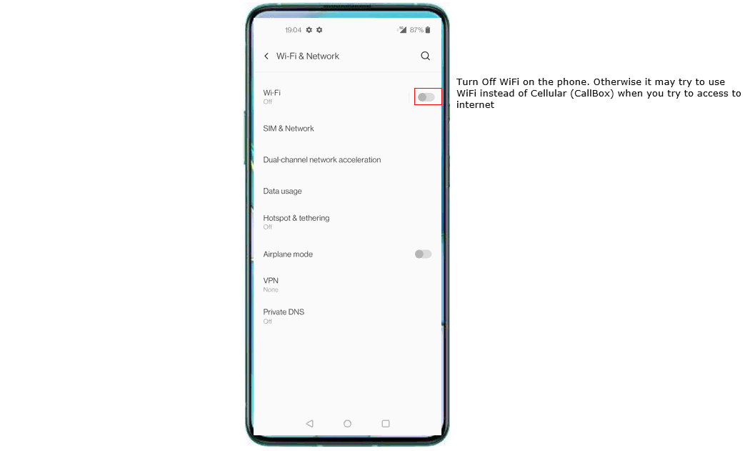
The first recommended step is to disable WiFi on the UE. In most smartphones, WiFi has higher priority than cellular data for internet access, so if WiFi is still enabled, the UE may access the internet through WiFi instead of through the cellular connection provided by the Callbox. In that case, the test result can be misleading because the browser, YouTube, Speedtest, or other applications may work even though the Callbox cellular data path is not actually being used.
In this example, WiFi is turned off on the phone before starting the test. Depending on UE firmware implementation, cellular data may still be preferred in some cases, but disabling WiFi is safer and makes the test result more consistent.
Also make sure that Airplane mode is off. If Airplane mode is on, the UE radio may be disabled and the UE will not attach to the Callbox network. The expected starting condition is that WiFi is off, Airplane mode is off, and the UE is ready to connect through cellular service only.
- First thing I would suggest is to disable WiFi on UE, otherwise most of UE would give higher priority to WiFi for data connection than cellular connection. So if WiFi is not disabled, UE would try to connect internet over WiFi instead of celluar network. (
NOTE : This behavior would vary depending on UE firmware implementation, but it would be better to disable WiFi for consistency of the test). - Make it sure that your UE is in Airplane mode ON
Initial Attach
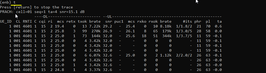
Start the initial attach by turning Airplane mode off, or by powering on the UE. After that, confirm that the UE is connected to the Callbox. The simplest way to check the connection is to go to the eNB/gNB screen and run the t command. This command shows real-time radio activity, so if the UE is attempting access or has already connected, you should see PRACH activity and UE traffic statistics.
In this example, the trace first shows PRACH activity, which means the UE has transmitted a random access preamble toward the Callbox. The line PRACH: cell=01 seq=1 ta=4 snr=15.1 dB indicates that the Callbox detected PRACH on cell 01, with sequence index 1, timing advance value 4, and SNR 15.1 dB. This confirms that the UE is reaching the Callbox over the air.
After the access procedure, the UE appears in the trace table with UE_ID 1. The table shows downlink and uplink status such as RNTI, CQI, MCS, bitrate, SNR, HARQ retransmission, received uplink packets, uplink bitrate, PHR, pathloss, and timing advance. Seeing non-zero DL or UL bitrate and changing packet counters confirms that the UE is not only detected at the radio level but also exchanging traffic with the Callbox.
Once the UE connection is confirmed, check whether the UE has been assigned an IP address. This is an important step because internet access cannot work unless the UE receives at least one IP address from the core network. You should remember this UE IP address because it can be used later for ping tests or troubleshooting.(
In this example, the ue command is run from the mme screen. The output shows one registered UE with SUPI 001010123456789, IMEISV 8690570563562913, and registration status Y. The REG value Y indicates that the UE is registered to the core network. The #BEARER value is 1, which means one bearer or PDU session is established for this UE.
The most important field in this check is IP_ADDR. In this example, the UE is assigned IP address 192.168.3.2. This means the UE has successfully completed the data-session establishment part and received an IP address from the Callbox core network. Since the IP address belongs to the 192.168.3.x subnet, it is expected to be associated with the tun1 side, where the Callbox-side interface address is typically 192.168.3.1 in the earlier example.
At this point, the UE is attached, registered, and assigned an IP address. The next step is to verify whether IP packets can actually pass between the UE, the Callbox tun interface, the default gateway, and the external internet..

Ping from Callbox to UE and confirm that the ping works.
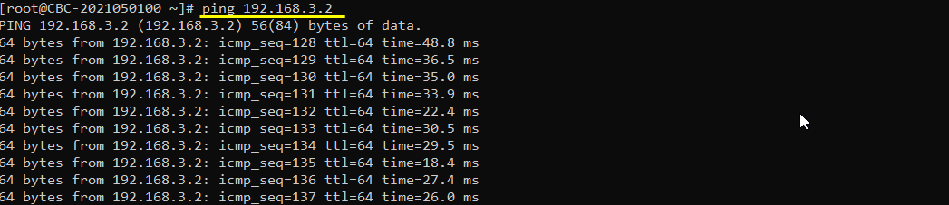
After confirming that the UE has been assigned an IP address, try pinging the UE IP address from the Callbox. In this example, the UE IP address is 192.168.3.2, so the command ping 192.168.3.2 is used on the Callbox Linux prompt.
The output shows normal ICMP replies from 192.168.3.2, with increasing icmp_seq values and response times such as 48.8 ms, 36.5 ms, 35.0 ms, and so on. This confirms that the Callbox can reach the UE over the established cellular data path.
This test is useful because it verifies the local IP connectivity between the Callbox core network side and the UE. At this stage, the packet does not need to go out to the external internet yet. It mainly confirms that the UE IP address is valid, the corresponding tun interface is working, the bearer or PDU session is active, and packets can pass between the Callbox and the UE.
If this ping fails, check whether the UE is still attached, whether the UE has a valid IP address, whether the correct UE IP address is being used, and whether the UE firewall or device policy blocks ICMP ping responses.
Trying Ping from UE over Internet
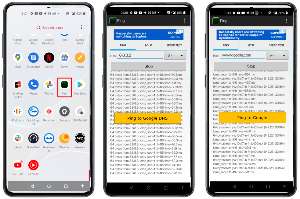
Now check whether the UE can reach the internet through the Callbox. For this test, I installed a ping application on the DUT, but you can use any application that can send ICMP ping from the UE. The important point is that the test should be performed from the UE while WiFi is disabled, so that the packet goes through the cellular connection established by the Callbox.
First, ping 8.8.8.8 from the UE. Since 8.8.8.8 is an IP address, this test checks basic IP connectivity without depending on DNS name resolution. In this example, the UE receives normal ping replies from 8.8.8.8, so the UE packet is successfully passing through the cellular radio link, the Callbox core network, the tun interface, NAT, default gateway, and then out to the internet.
Next, ping [www.google.com](http://www.google.com) from the UE. This test checks not only internet connectivity but also DNS resolution. In this example, [www.google.com](http://www.google.com) is resolved to a Google server address, and the UE receives normal ping replies. This confirms that DNS is also working properly for the UE.
If ping to 8.8.8.8 works but ping to [www.google.com](http://www.google.com) does not work, the UE internet path is probably working, but DNS configuration may have a problem. If both tests fail, check the earlier steps again, including UE IP address assignment, Callbox-to-UE ping, routing table, NAT table, IP forwarding, default gateway, and Callbox internet connectivity.
Trying Internet from UE
After all previous checks are confirmed, you can try real internet traffic from the UE. At this point, the UE has already attached to the Callbox, received an IP address, passed the ping test to the Callbox, and confirmed external IP/DNS connectivity through ping tests. Now the final step is to verify that normal user applications can access the internet through the cellular connection.
In this example, three different types of traffic are tested. First, web browsing is tested by opening a website from the UE browser. This confirms that normal HTTP/HTTPS traffic can pass through the Callbox data path. Next, YouTube is tested to confirm that video streaming traffic also works. Finally, Speedtest is performed to check that higher-volume data traffic can be transferred over the Callbox internet connection.
All three tests worked successfully in this example. This confirms that the UE is using the cellular data connection through the Callbox to reach the internet, and that the overall path from UE to eNB/gNB, core network, tun interface, NAT, default gateway, DNS, and external internet is working properly.
When doing this test, make sure again that WiFi on the UE is disabled. Otherwise, the browser, YouTube, or Speedtest may use WiFi instead of the cellular connection, and the result may not represent the Callbox data path.

Analyzing Traffic with WebGUI
This section is optional and can be skipped if you only want to confirm basic UE internet access. It is assumed that you already know how to connect to the Amarisoft WebGUI and perform basic log browsing. If you are not familiar with WebGUI setup or basic operation, refer to the WebGUI tutorial (WebGUI.) first.
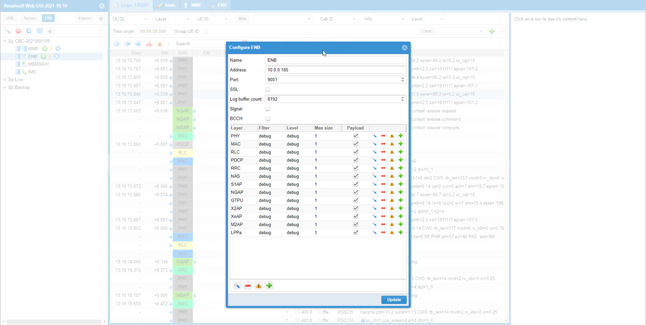
WebGUI is useful when you want to analyze the traffic and protocol behavior in more detail while the UE is accessing the internet. In this example, the WebGUI is connected to the Callbox, and the ENB log configuration window is opened. From this window, you can enable log collection for different protocol layers such as PHY, MAC, RLC, PDCP, RRC, NAS, S1AP, NGAP, GTPU, and other interfaces.
For internet access testing, the most relevant layers are usually RRC, NAS, PDCP, and GTPU. RRC and NAS help you confirm that the UE registration, attach, and bearer or PDU session establishment procedures are completed correctly. PDCP helps you see user-plane packet activity at the radio protocol side. GTPU is especially important because it shows user-plane tunnel traffic between the eNB/gNB side and the core network side. If the UE is browsing, running YouTube, or doing Speedtest, you should see corresponding user-plane traffic in these layers.
In this example, the WebGUI is configured to receive logs from the ENB at address 10.0.0.185 using port 9001. The exact address may be different in your setup depending on the IP address assigned to your Callbox network interface. Once the log connection is established and the required layers are enabled, you can start internet traffic from the UE and observe how the packets appear in the WebGUI logs.
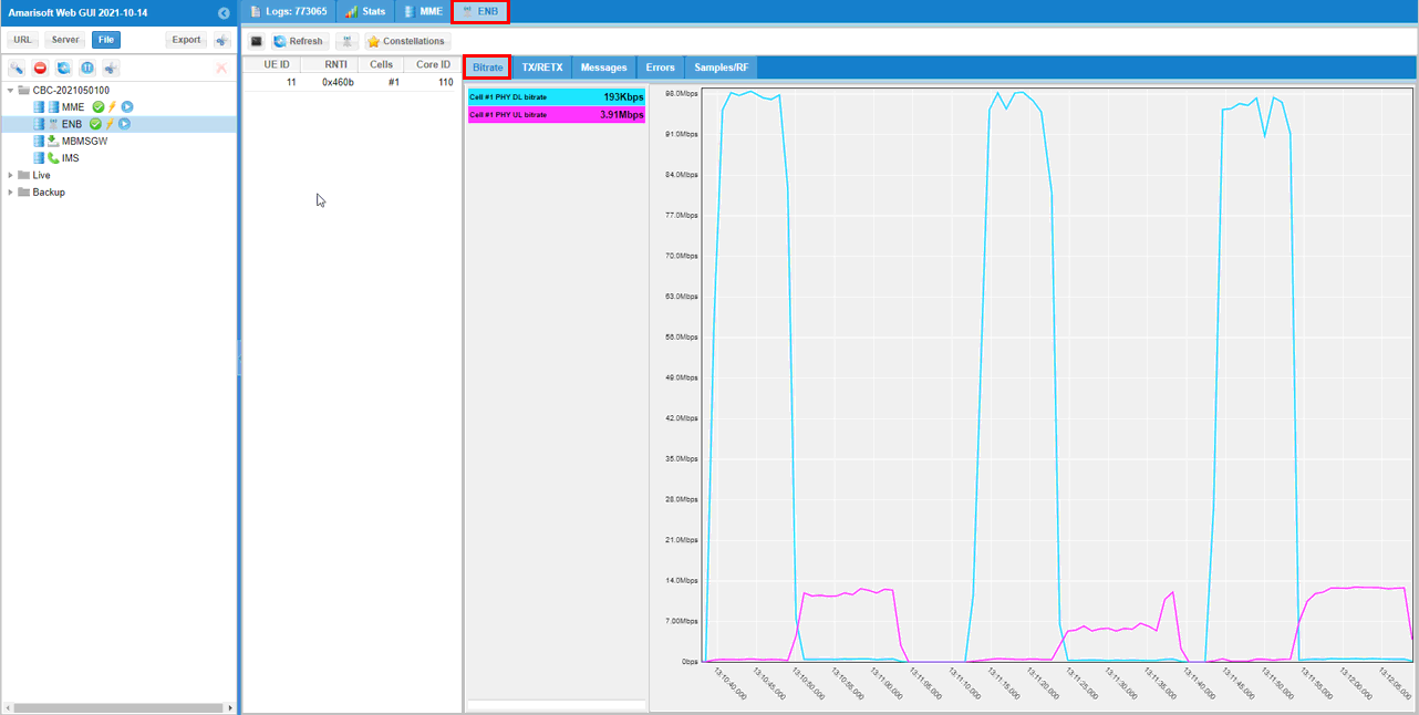
Select the Throughput tab to view the throughput plots in WebGUI. This is useful when you want to visually confirm how much traffic is being generated while the UE is browsing, streaming, downloading, or running Speedtest.
In the left panel, WebGUI shows different throughput items. Global represents the aggregated throughput of all UEs connected to the cell. Under Global, you may also see numbered items, and each number corresponds to a specific UE ID. By selecting one of these numbered items, you can plot the throughput for a specific UE instead of the total cell throughput.
In this example, the ENB statistics view is selected, and the Bitrate tab is opened. The plot shows both downlink and uplink bitrate over time. The downlink throughput increases significantly during high-traffic periods, such as Speedtest or video download, while the uplink throughput remains lower because the main traffic in this test is download-oriented. This kind of plot is very helpful for confirming that the UE internet traffic is actually passing through the Callbox cellular data path, not through WiFi or another interface.
If multiple UEs are connected, the Global plot shows the combined throughput of all UEs, so it may not be easy to identify which UE generated the traffic. In that case, select the numbered UE item corresponding to the UE ID observed in the eNB or MME trace, and check the throughput for that specific UE.
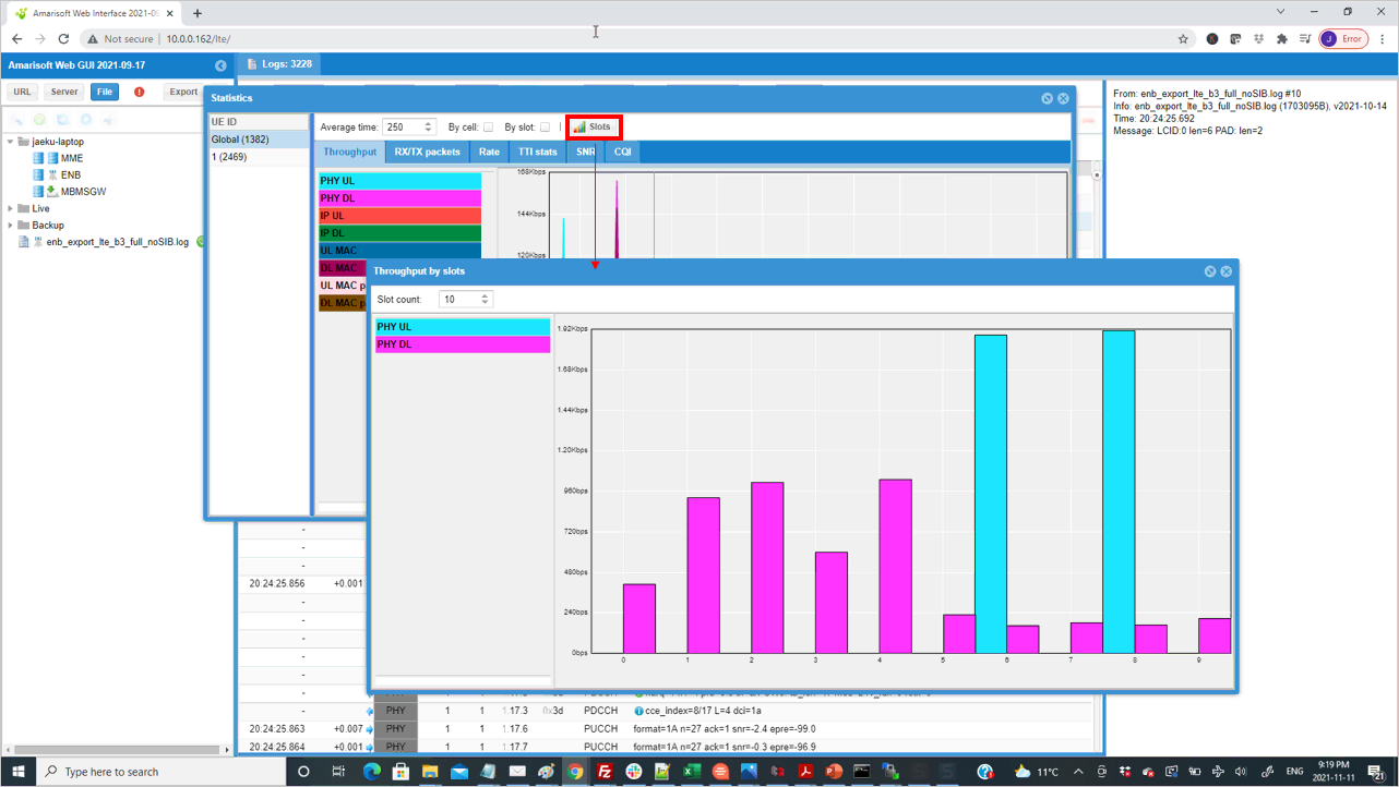
If you click the Slots button, WebGUI shows the selected KPI as a per-slot view. For example, when the Throughput tab is selected and then Slots is clicked, WebGUI opens a separate window showing throughput for each slot.
In this example, the throughput-by-slots window shows PHY UL and PHY DL throughput separately for each slot. This view is useful when you want to check how the traffic is distributed across slots instead of only looking at the average throughput over time. The normal throughput plot gives a time-domain trend, while the slot-based plot gives a more detailed view of which slots are carrying uplink or downlink traffic.
The Slot count field controls how many slots are shown in the plot. In this example, the slot count is set to 10, so the graph displays slot indexes from 0 to 9. The vertical bars represent the measured throughput for each slot, and different colors represent different directions or layers such as PHY UL and PHY DL.
This view can be useful for checking whether traffic is mostly downlink or uplink, whether scheduling is happening across multiple slots, and whether the traffic pattern matches the expected behavior for the test. For a simple internet access test, this is not mandatory, but it can be helpful when you want to confirm the detailed radio-side scheduling behavior during browsing, ping, YouTube, or Speedtest traffic.
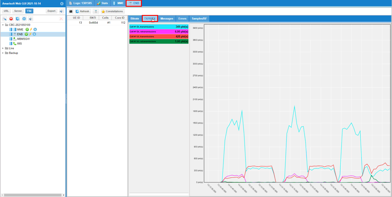
If you want to check the radio link quality during the internet access test, it is useful to look at the TX/RETX plot. This plot shows how many packets are transmitted and how many packets are retransmitted. Retransmission happens when the original transmission is not successfully received, so this can be used as a simple indicator of radio link quality.
In this example, the ENB statistics view is selected and the TX/RETX tab is opened. The plot shows downlink transmissions, downlink retransmissions, uplink transmissions, and uplink retransmissions separately. When the UE generates internet traffic, the number of transmissions increases. If the radio link quality is good, the retransmission count should remain relatively low compared to the total transmission count.
The downlink transmission curve is much higher than the uplink curve because this test traffic is mostly download-oriented, such as browsing, YouTube, or Speedtest download. The retransmission curves are lower than the corresponding transmission curves, which indicates that packets are mostly being delivered successfully, although some retransmissions still occur. A small amount of retransmission is normal in a real radio environment.
If retransmission becomes very high, it usually indicates that the radio link condition is not good enough. Possible causes include weak signal, poor antenna connection, too much distance between UE and Callbox antenna, RF interference, incorrect RF cabling, or unsuitable gain setting. In that case, check the physical RF setup, UE position, antenna connection, RSRP/SINR, and scheduler or MCS behavior before interpreting the internet speed result.
Analyzing IP Traffic
You may not do this kind of analysis often, but there would be some cases where you need to do troubleshooting (e.g, UE getting no internet access) and you need to check IP traffic flow at every check points along the data path. Here I will show you various ways of capturing IP traffic at multiple different check points.
The main purpose of this analysis is to confirm the data path between every check points are properly connected. If there is any of broken check points, internet access would not work properly.
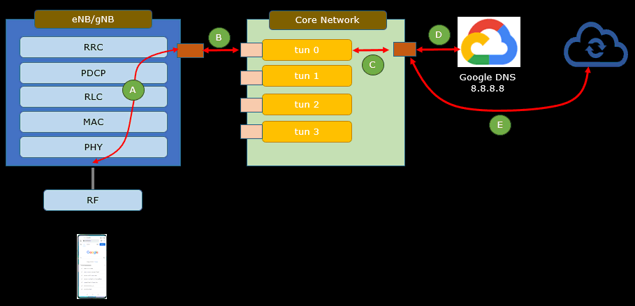
Once you got everything working as described in CHECK UP BEFORE TRYING UE CONNECTION, get UE connected to Callbox (eNB or gNB). Then capture IP packet at every checkpoint marked below. To do this, you need to capture every IP packet flowing outside of the eNB/gNB using Wireshark (or tcpdump) and every IP packets following inside of dNB/gNB using WebGUI.
In this figure, checkpoint A represents the traffic inside the eNB/gNB protocol stack. This is where you can check whether user-plane traffic is passing through the radio protocol layers such as PDCP, RLC, MAC, and PHY. This part is usually checked with WebGUI because the traffic is inside the Amarisoft eNB/gNB processing chain rather than a normal Linux network interface.
Checkpoint B represents the GTP-U side between the eNB/gNB and the core network. This is useful for checking whether the user-plane packets are properly encapsulated and forwarded between the radio access side and the core network side. If the UE generates traffic but nothing is seen at this point, the issue may be around bearer/PDU session establishment, GTP-U tunnel setup, or user-plane forwarding between eNB/gNB and core.
Checkpoint C represents the tun interface on the core network side. For example, if the UE IP address is 192.168.3.2, the corresponding interface may be tun1 with gateway-side address 192.168.3.1. Capturing on this tun interface confirms whether the UE IP packet reaches the core network side as a normal IP packet after decapsulation from the cellular user-plane tunnel.
Checkpoint D represents the external network interface of the Callbox, such as eno1 in this example. At this point, the packet should already be routed and NATed toward the external network. Capturing here is useful to confirm whether packets from the UE are actually leaving the Callbox toward the default gateway.
Checkpoint E represents the final external path toward the internet server, such as Google DNS 8.8.8.8 or another public server. You usually cannot capture directly inside the internet, but you can infer this part by checking whether requests sent from the UE receive responses, or by observing packet exchange on the Callbox external interface.
By comparing captures from these checkpoints, you can narrow down where the problem is located. If packets are seen at A but not at B, the issue is likely between the radio stack and GTP-U forwarding. If packets are seen at B but not at C, the issue may be around the core-side tunnel handling. If packets are seen at C but not at D, check routing, NAT, and IP forwarding. If packets are seen at D but no response comes back, check the default gateway, firewall, DNS, or external network path.
tcpdump
Basically Amarisoft Callbox PC is running on command line mode. You can enable Graphic Mode on Callbox PC(Fedora) and run 'lte service' on a terminal, but this is not strongly recommended due to possible performance issue). A command way to capture the IP packets in this kind of situation is to use tcpdump as shown here. (
This example shows how to capture packets on the eno1 interface. In my setup, eno1 is the gateway Ethernet interface of the Callbox, so packets going between the Callbox and the external network can be captured from this interface. The interface name may be different on your system, so use the correct external interface name shown by ifconfig, ip addr, or ip route.
The command tcpdump -i eno1 -w /tmp/internet.pcap starts packet capture on eno1 and saves the captured packets into /tmp/internet.pcap. The -i eno1 option specifies the interface to capture from, and the -w /tmp/internet.pcap option writes the captured packets into a pcap file instead of printing them only on the terminal. This file can later be copied to another PC and opened with Wireshark for easier analysis.
After starting tcpdump, generate traffic from the UE, for example ping 8.8.8.8, open a browser, or run Speedtest. While the traffic is running, tcpdump keeps capturing packets. To stop the capture, press Ctrl + C. In this example, tcpdump reports that 499 packets were received by the filter and 0 packets were dropped by the kernel, which means the capture was completed without packet loss at the tcpdump level.
The same method can also be used for tun interfaces. For example, if the UE IP address belongs to the 192.168.3.x subnet, you may capture on tun1 instead of eno1. Capturing on tun1 shows packets closer to the UE/core side, while capturing on eno1 shows packets after routing and NAT toward the external network. Comparing these two captures helps identify whether the UE packet reaches the core network side and whether it is correctly forwarded out to the internet.

After stopping tcpdump, make sure that the pcap file is saved properly. In this example, the command ll /tmp/*.pcap is used to list all pcap files stored under /tmp.
The output shows several captured files, including /tmp/internet.pcap, /tmp/test1.pcap, and /tmp/test.pcap. The file size and timestamp confirm that the files were created and saved. For example, /tmp/internet.pcap has a non-zero file size, so it contains captured packets and can be used for further analysis.
Once the pcap file is confirmed, you can copy it to your local PC and open it with Wireshark. Analyzing the file in Wireshark is usually much easier than reading tcpdump output directly on the Callbox terminal because Wireshark provides packet filtering, protocol decoding, packet details, and traffic flow visualization.
For example, after copying /tmp/internet.pcap to your PC, you can check whether UE packets are leaving through the external interface, whether DNS or ICMP packets are present, and whether response packets are coming back from the internet. If you capture both the tun interface and the external interface, comparing those two pcap files can help you identify whether the packet is blocked before NAT, after NAT, or somewhere in the external network.

Wireshark
For easier troubleshooting, you can run Wireshark from a GUI-based PC while the actual Wireshark process is running on the Callbox. In this example, I use an Ubuntu PC and connect to the Callbox with X11 forwarding by running ssh -X root@10.0.0.185. The -X option is important because it allows the Wireshark GUI window from the Callbox to be displayed on the local Ubuntu PC.
After logging in to the Callbox through SSH, run wireshark from the terminal. The Wireshark window will appear on the local PC, but the packet capture is performed on the Callbox. This means Wireshark can directly see the Callbox network interfaces, including the external Ethernet interface and the tun interfaces created by the Amarisoft service.
In this example, eno1 is the gateway Ethernet interface used for internet access. Your Callbox may use a different interface name depending on the hardware and Linux configuration. You should also see tun0, tun1, tun2, and tun3 while the lte service is running. These tun interfaces are created by the Callbox and are used for UE IP traffic on the core network side.
You can select a specific interface if you want to capture traffic only at one checkpoint. For example, selecting eno1 captures packets going out to or coming back from the external network, while selecting tun1 captures packets closer to the UE-side IP subnet if the UE is using the 192.168.3.x address range. In my case, I usually select any so that packets from all interfaces are captured in a single capture session. This makes it easier to compare packet flow across multiple interfaces without starting separate captures.
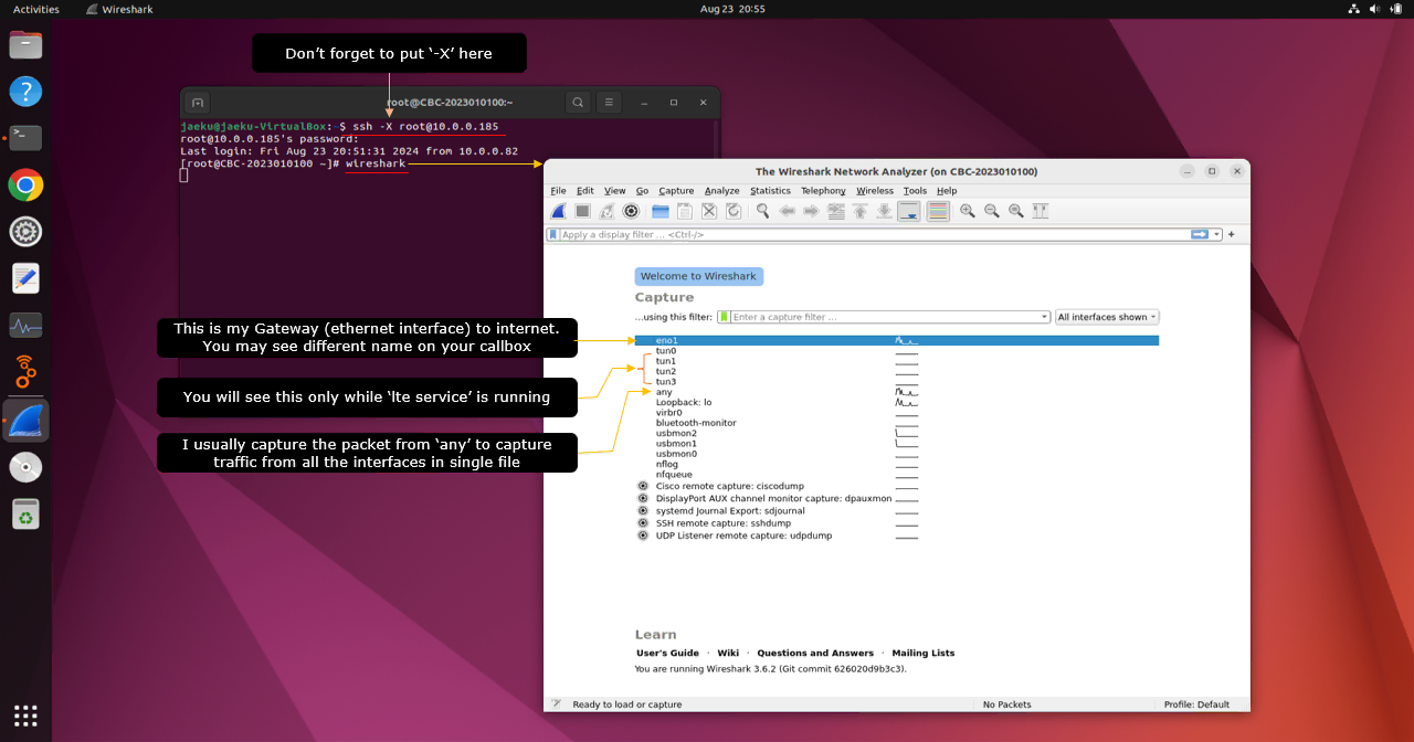
Once I started the capture, I did the followings
i) get UE connected to Callbox (LTE or NR)
ii) figure out the IP assigned to the UE (You can find the UE IP in (mme) command as shown here)
iii) ping from Callbox to UE for a couple of seconds
iv) ping from UE to the callbox (You may need to install a ping app on your UE to do this)
v) ping from UE to 8.8.8.8
vi) Analyze traffic in Wireshark
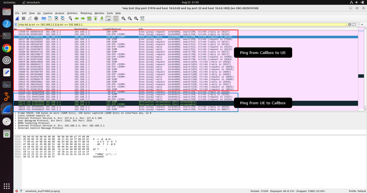
You should be able to see all IP traffic flowing outside the eNB/gNB protocol stack in Wireshark, as shown below. This capture is useful for checking whether packets are actually passing through the Callbox Linux network interfaces.
In this example, the Wireshark display filter is set to show ICMP traffic between the Callbox-side address and the UE-side address. The packets show ping traffic between 192.168.2.1 and 192.168.2.2. Here, 192.168.2.1 is the Callbox-side tun interface address, and 192.168.2.2 is the UE IP address assigned by the core network.
The first group of packets shows ping from the Callbox to the UE. You can see ICMP Echo request packets from 192.168.2.1 to 192.168.2.2, followed by ICMP Echo reply packets from 192.168.2.2 back to 192.168.2.1. This confirms that the Callbox can send IP packets to the UE and receive responses through the established cellular data path.
The second group of packets shows ping from the UE to the Callbox. In this case, the ICMP Echo request is sent from the UE IP address to the Callbox tun interface address, and the Echo reply is sent back from the Callbox to the UE. This confirms that the UE can also initiate IP traffic toward the Callbox.
This kind of capture is a good starting point before checking internet traffic. If ping between the Callbox tun interface and the UE does not appear correctly in Wireshark, the problem is still inside the local UE-to-Callbox data path, so you should check UE IP assignment, bearer or PDU session establishment, tun interface, and cellular user-plane connectivity first. If this local ping works but internet access still fails, then the next step is to check packet forwarding from the tun interface to the external interface, NAT, default gateway, DNS, and the return path from the external network.
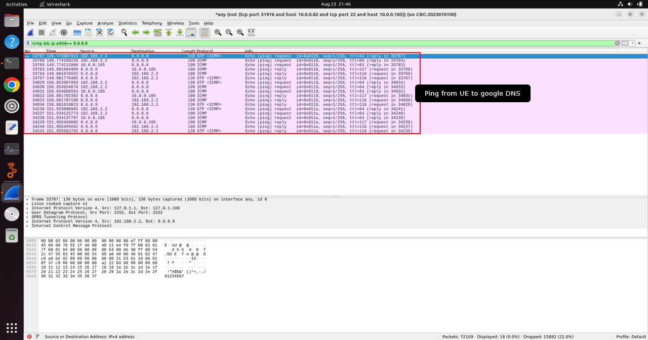
This capture shows the ping traffic from the UE to Google DNS 8.8.8.8. This is a very useful test because it confirms that UE traffic is not stopping at the Callbox, but is being forwarded out toward the external internet.
In this example, the UE IP address is 192.168.2.2 and the destination is 8.8.8.8. In the capture, you can see ICMP Echo request packets generated from 192.168.2.2 toward 8.8.8.8, and ICMP Echo reply packets coming back from 8.8.8.8 toward 192.168.2.2. This confirms that the UE packet goes through the cellular data path, reaches the Callbox tun interface, is forwarded and NATed through the external interface, reaches Google DNS, and then the response packet returns back to the UE.
Because this capture was taken on the Callbox using the any interface, you may see the same packet more than once or see packets from different interfaces in the same capture. This is expected when capturing from all interfaces. For troubleshooting, this is often helpful because you can observe both the UE-side packet and the external-side packet in one capture.
If you see the ICMP request from the UE but do not see any reply from 8.8.8.8, the UE packet may be leaving the Callbox but the return path may be blocked, or NAT/default gateway may not be working correctly. If you do not even see the ICMP request from the UE, then the problem is earlier in the path, such as UE IP assignment, bearer/PDU session, tun interface, or local UE-to-Callbox connectivity.
WebGUI
If you don't get ping reply from any of the attempt you did above, the first thing you need to check is to see the packet is going through eNB/gNB software stack. You can check it out through WebGUI.
My personal trick for debugging is to enable log collection for as many ENB and MME elements as possible, even if some of them do not seem necessary at the beginning. When troubleshooting an IP data path issue, you may not know in advance which layer will give the most useful clue, so collecting more log elements can save time later.
For IP traffic troubleshooting, I usually pay special attention to GTPU because GTP-U is the user-plane tunnel used to carry UE IP packets between the eNB/gNB side and the core network side. If the UE sends ping or other internet traffic, but the packet does not appear correctly in the expected Linux interface capture, checking GTPU logs can help confirm whether the packet is passing through the Amarisoft user-plane tunnel.
In this example, log capture is enabled for the ENB elements, and the GTPU Max size is increased to 1024. The Max size controls how much payload data is captured and displayed in the log. Increasing this value can be useful when you want to inspect more of the packet content during IP debugging. This may not always be necessary for normal operation, but it is helpful when you need to analyze why UE internet access is not working.
After changing the log settings, click Update to apply the configuration. Then generate traffic from the UE, such as ping to the Callbox, ping to 8.8.8.8, or browsing, and check whether the corresponding GTPU and related user-plane logs appear in WebGUI.
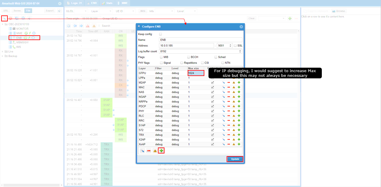
Enable log capture for every MME element and increase the GTPU Max size.
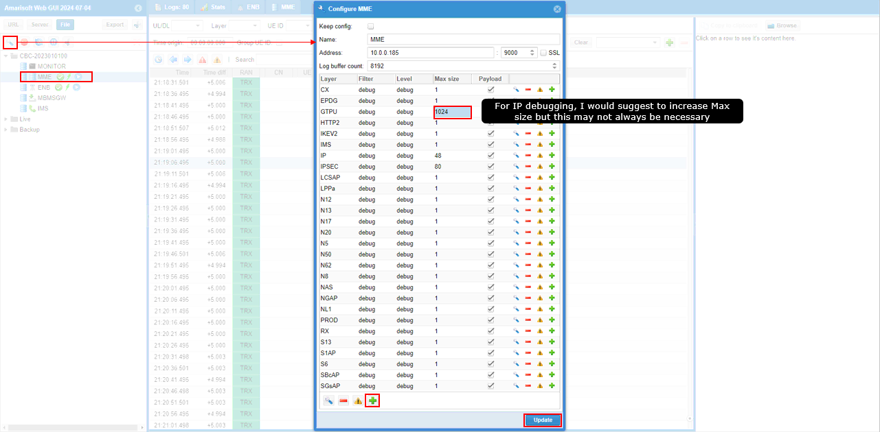
In addition to the ENB side, it is also useful to enable log capture on the MME side when debugging UE IP traffic. The MME side includes the core network processing, so it can show whether the UE user-plane packet is properly handled after it passes through the radio access side and reaches the core network side.
In this example, the MME configuration window is opened from WebGUI, and log capture is enabled for the available MME elements. For IP data path troubleshooting, GTPU is one of the most important layers to check, so the GTPU Max size is increased to 1024. This allows WebGUI to capture and display a larger part of the GTPU packet payload, which can be helpful when you want to inspect ICMP, DNS, or other IP packet contents inside the tunnel.
This setting may not always be necessary for normal internet access testing, but it is helpful when the UE is attached and assigned an IP address but internet traffic still does not work. After changing the MME log setting, click Update to apply the configuration. Then generate traffic from the UE again, such as ping to the Callbox, ping to 8.8.8.8, or ping to www.google.com, and check whether corresponding GTPU and IP-related logs appear on the MME side.
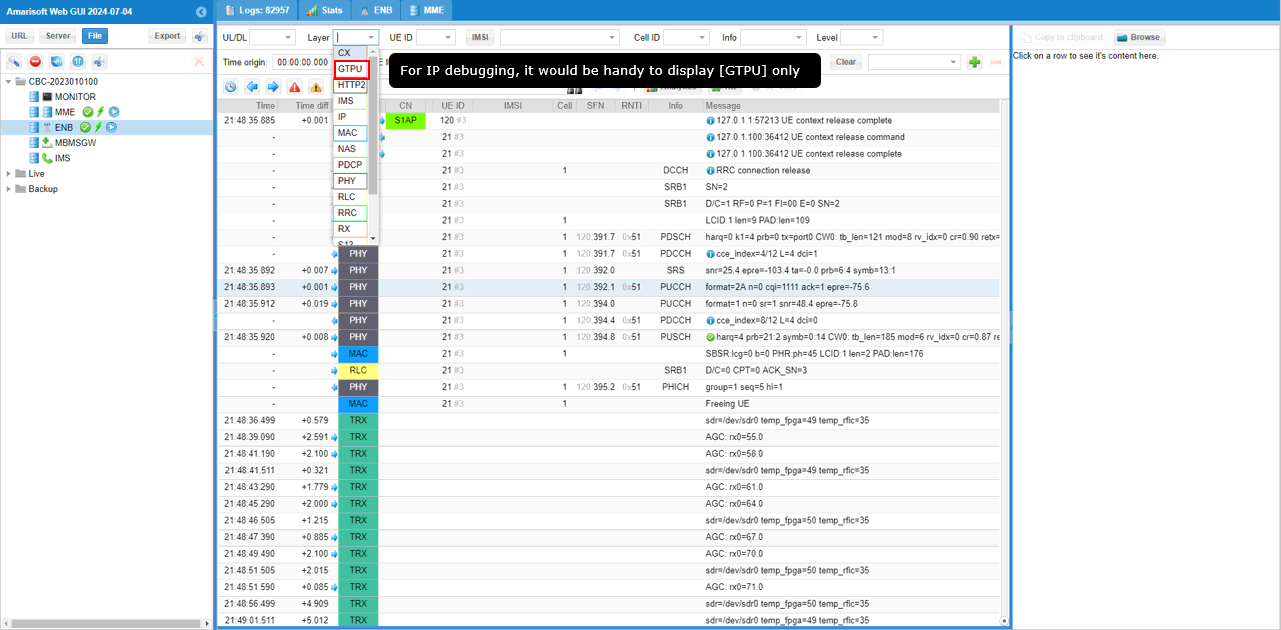
In most IP packet analysis cases, the first checkpoint to look at is GTPU. Therefore, it is useful to set the WebGUI display filter to GTPU only.
GTPU is important because it carries the UE user-plane IP packets between the eNB/gNB side and the core network side. When the UE sends traffic such as ping, DNS query, browsing, or Speedtest traffic, the corresponding user-plane packets should normally appear as GTPU traffic before they are delivered to the core-side IP interface.
In this example, the Layer filter in WebGUI is opened and GTPU is selected. This makes the log view show only GTPU-related messages, so you can focus on the user-plane tunnel traffic without being distracted by other protocol logs such as PHY, MAC, RLC, RRC, NAS, or S1AP/NGAP.
For IP debugging, this is usually a convenient first filter. If GTPU packets are shown when the UE generates traffic, it means that the packet is at least passing through the Amarisoft user-plane tunnel. If no GTPU packet appears even though the UE is sending traffic, the problem may be earlier in the data path, such as UE bearer/PDU session establishment, radio-side user-plane scheduling, or the connection between the UE and eNB/gNB stack.
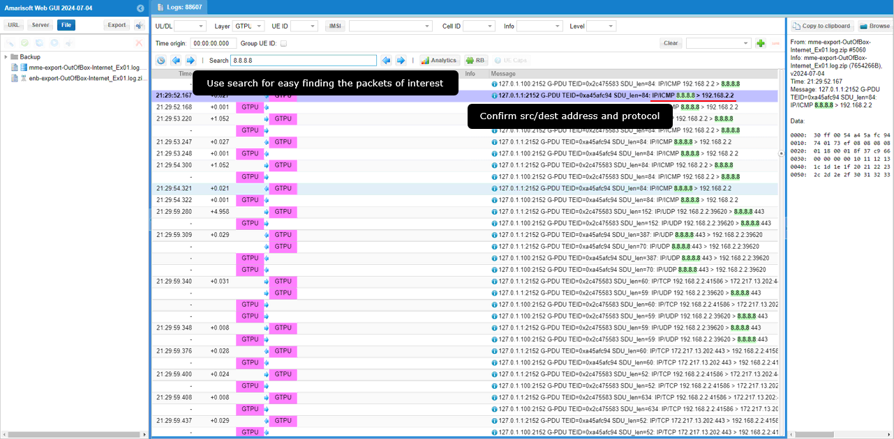
Now the GTPU filter is applied and all GTPU packets are shown in WebGUI. The next step is to confirm that the ping packets you generated are visible in this GTPU log. In this example, the search field is used with 8.8.8.8, which makes it easier to find the packets related to ping toward Google DNS.
In the GTPU log, check the source address, destination address, and protocol information. For example, you can see IP/ICMP packets from 192.168.2.2 to 8.8.8.8 and also packets from 8.8.8.8 back to 192.168.2.2. This confirms that the UE ping packet is carried inside the GTPU tunnel and that the response packet also comes back through the same user-plane path.
If the Wireshark capture shows the ping packet but the WebGUI GTPU log does not show the corresponding packet, or if WebGUI shows only one direction but Wireshark shows something different, it usually means that one of the connection points along the data path is not working as expected. In that case, follow each ping packet step by step across WebGUI and Wireshark. Check whether the packet appears in GTPU, then whether it appears on the tun interface, then whether it appears on the external interface, and finally whether the reply packet comes back.
This kind of troubleshooting can be tedious, but there is no easy shortcut when the data path is broken. The safest method is to trace the same packet at each checkpoint and identify the first point where the expected packet disappears. That point usually indicates the broken link or the configuration item that needs to be checked, such as bearer/PDU session handling, GTPU forwarding, tun interface, routing, NAT, IP forwarding, default gateway, or firewall behavior.
Tips
Throughput Impact with WiFi
If you connect the Callbox to the internet over WiFi only for remote control, such as SSH access or normal maintenance operation, almost any working WiFi adapter or WiFi range extender can be used as long as the Callbox can successfully connect to the network. However, if you use the same WiFi path for UE internet throughput testing, the WiFi connection itself may become the bottleneck, so the measured UE throughput may not represent the actual cellular link capability.
Most WiFi dongles, even relatively high-end ones, may support only a little over 1 Gbps in ideal conditions, and many common USB WiFi dongles support only several hundred Mbps in real usage. In addition, the actual throughput provided by your WLAN service provider, access point, or local network may be lower than the theoretical WiFi capability.
If you use a WiFi range extender and connect the Callbox Ethernet port to the extender Ethernet port, also check the Ethernet port speed of the extender. Many WiFi range extenders have only a 100 Mbps Ethernet port, not a Gigabit Ethernet port. In that case, the UE internet throughput can be limited to around 100 Mbps even if the cellular radio link and Callbox configuration can support much higher throughput.
For simple internet access confirmation, this limitation may not matter much. However, for throughput measurement, Speedtest, large file download, or performance comparison, it is better to use a stable wired Gigabit Ethernet connection whenever possible. This reduces the chance that the external internet path, WiFi adapter, or range extender becomes the limiting factor instead of the cellular test setup itself.
- Most WiFi dongle (even high end dongle) support only little bit over 1Gbps. Most of regular / common WiFi dongle support only several hundreds of Mbps
- You may not have very high throughput provided by the WLAN service provider.
- If you use Wired LAN connection attached to WiFi Range Extender, the throughput over internet can be restricted up to 100 Mbps since most of Wired LAN port on WiFi Range extender is 100 Mbps port (NOT Gbit port)
Selecting Proper Subnet for WiFi Network
When you connect the Callbox or UEsim to a WiFi network, be careful about the subnet used by the WiFi network. It is better not to use a subnet that may already be used by any Callbox or UEsim network interface. If the WiFi subnet overlaps with a subnet used internally by the Callbox or UEsim, Linux routing may become ambiguous and you may see strange behavior. In some cases, not only the Callbox but also other devices in the same WiFi network can be affected by this subnet collision.
For this reason, try to avoid using 192.168.1.x and also avoid 192.168.y.x where y ranges from 2 through 10. With the default mme.cfg, avoiding these ranges is usually enough because the Callbox commonly uses several 192.168.x.x subnets for tun interfaces and UE IP allocation. However, if you modify mme.cfg and configure additional UE subnets, you should also avoid those subnets on the WiFi access point side.
Most WiFi access points or routers allow you to change the LAN subnet. For example, instead of using 192.168.1.x or 192.168.2.x, you can configure the WiFi router to use a different subnet such as 10.0.0.x. This reduces the chance of subnet collision between the external WiFi network and the internal Callbox UE networks, and makes the routing and NAT behavior much cleaner during internet access testing.
- 192.168.1.x
- 192.168.y.x, where Y ranges from 2 through 10 (If you use default mme.cfg this would be enough, but if you modify mme.cfg to use other subnets you need to avoid that subnet as well).
Distance between WiFi Access Point and WiFi Range Extender
A WiFi range extender is designed to extend WiFi coverage, but its placement is important. If the WiFi access point and the range extender are placed too close to each other, they may interfere with each other or create an unstable WiFi path instead of improving the connection.
For this reason, do not place the WiFi access point and the WiFi range extender too close to each other. The range extender should be located at a position where it can still receive a good signal from the access point, but far enough away to actually extend the coverage. If the extender is too far from the access point, the backhaul connection may become weak. If it is too close, it may not provide any real benefit and may even degrade the connection.
This is especially important when the Callbox uses the WiFi extender path for UE internet access testing. A poor or unstable WiFi extender connection can reduce throughput, increase latency, or cause intermittent packet loss. In that case, the problem may look like a cellular data issue, even though the real bottleneck is the WiFi backhaul between the access point and the extender.