NR SA CSI Report
The purpose of this tutorial is to show you how to configure CSI-RS and Report configuration. This would be the most complicated configuration in 5G NR and many parameters are involved in Amarisoft configuration as well. Main purpose of this tutorial is to show how each of the configuration parameter in enb.cfg is associated with RRC Configuration for CSI Report.
Amarisoft gNB provides two different ways of configuring CSI RS/CSI Report as listed below :
- Manual Configuration : This is the way you should configure every details of RRC configuration required for CSI Report and CSI RS. This is the only option if you are using the gNB software before 2022-06-17. You still can use this option even after 2022-06-17 if you want to control all the detailed parameters (like periodicity and position of all the necessary CSI RS) and you exactly understand what you should do.
- Auto Configuration : This is the way you just configure a few most fundamental parameters (e.g, CSI Report Quantity) and gNB software configure all other parameters which are necessary to enable the specified Report. In order to use this feature, you need to use the release 2022-06-17 or later.
Table of Contents
- NR SA CSI Report
- Introduction
- Summary of the Tutorial
- Test Procedure Summary
- For those frustrated with 5G CSI
- Plan before Doing
- Test Setup
- Key Configuration Parameters
- Reference Configuration : Auto CSI Configuration
- Test 1 : Periodic CSI Report
- Configuration
- Log Analysis
- Sub Test 1 : RI-PMI-CQI
- Sub Test 2 : RI-CQI
- Sub Test 3 : RI-CQI with non-PMI-PortIndication
- Sub Test 4 : RSRP
- Sub Test 5 : RI-PMI-CQI with ri-restriction
- Sub Test 6 : ssb-RSRP
- Test 2 : Aperiodic CSI Report
- Test 3 : TCI
- Test 4 : CSI RS p32 - Periodic
- Test 5 : CSI RS and Physical Antenna Mapping - TRS
- RRC / NAS Signaling
- Tips
Introduction
Channel State Information Reference Signals (CSI-RS) play a pivotal role in the performance optimization and link adaptation mechanisms of 5G New Radio (NR) systems. CSI-RS are specialized downlink reference signals transmitted by the gNB (next-generation NodeB or 5G base station) to enable the User Equipment (UE) to accurately assess channel conditions and report this information back to the network. Such measurements are essential for closed-loop operations like beam management, mobility, and advanced MIMO (Multiple-Input Multiple-Output) techniques. The configuration of CSI-RS and their corresponding reporting mechanisms is inherently complex due to the extensive parameterization available in 5G NR, including aspects such as resource mapping, periodicity, frequency-domain positioning, and report quantization. Amarisoft’s gNB software provides a flexible and robust framework for configuring CSI-RS and CSI reporting, supporting both detailed manual configuration and streamlined auto-configuration modes. Understanding the mapping between high-level configuration files, such as enb.cfg, and the underlying RRC (Radio Resource Control) configurations is critical for network engineers seeking to optimize network performance, troubleshoot issues, or implement custom measurement strategies. This tutorial offers a comprehensive technical guide to configuring CSI-RS and CSI reporting in Amarisoft gNB, elucidating the interplay between configuration parameters and the resulting network behavior, while ensuring compatibility across software releases and deployment scenarios.
-
Context and Background
- 5G NR introduces advanced channel estimation and reporting mechanisms to support features such as massive MIMO, beamforming, and dynamic spectrum utilization.
- CSI-RS serve as the foundation for precise channel quality measurements, enabling UEs to provide feedback that drives adaptive transmission strategies.
- Amarisoft’s gNB software aligns with 3GPP standards, offering granular control over CSI-RS configuration for both pre- and post-2022-06-17 software releases.
-
Relevance and Importance
- Correct configuration of CSI-RS and reporting mechanisms is crucial for maximizing spectral efficiency and ensuring reliable UE connectivity in real-world deployments.
- This tutorial addresses the practical challenges of mapping configuration file parameters to RRC signaling, especially in the context of Amarisoft deployments.
- Understanding both manual and auto-configuration workflows empowers engineers to tailor network behavior to specific scenarios, balancing ease-of-use with fine-grained control.
-
Learning Objectives
- Comprehend the architectural role of CSI-RS in 5G NR and its impact on channel measurements and reporting.
- Gain hands-on familiarity with Amarisoft’s dual-mode (manual and auto) configuration paradigms for CSI-RS and reporting.
- Learn to associate enb.cfg parameters with RRC-level configurations for effective network tuning and troubleshooting.
- Acquire practical knowledge for maintaining compatibility with evolving Amarisoft software releases and leveraging new features efficiently.
-
Prerequisite Knowledge
- Familiarity with 5G NR concepts, especially radio protocol stack layers, reference signals, and measurement reporting.
- Basic understanding of Amarisoft gNB software usage and configuration file structure.
- Awareness of RRC signaling principles and general network configuration workflows.
-
Scope and Approach
- This tutorial focuses on high-level configuration strategies, parameter associations, and architectural context rather than raw message formats or ASN.1 definitions.
- It is designed to be accessible to radio engineers, system integrators, and advanced users aiming for optimal 5G NR network performance using Amarisoft gNB.
Summary of the Tutorial
This tutorial provides detailed procedures for configuring and testing various Channel State Information (CSI) reporting scenarios in a 5G NR Standalone (SA) environment using Amarisoft gNB. The focus is on configuration methodologies, verification steps, and test execution for both simple and advanced CSI use cases. Below are the summarized test procedures and methodologies as described in the tutorial:
-
General Test Preparation
- gNB configuration changes are required; default MME and IMS configurations can be kept.
- Key configuration steps include selecting duplex mode (TDD/FDD), DL antennas, band, frequency, and bandwidth.
- CSI configuration can be automatic (using resource_auto) for simplicity, or fully manual for advanced control.
- Verification of configuration is performed via logs, focusing on RRC Setup and CSI reporting via PUCCH.
-
Reference (Auto CSI) Configuration
- Use default gnb-sa.cfg with resource_auto to enable CSI RS and reporting with minimal parameter settings.
- Duplex mode, TDD pattern, bandwidth, and antenna settings are defined in the configuration file.
- AutoCSI simplifies configuration by automating resource and report setup; detailed configuration is possible with manual methods.
- Verification involves checking the log for proper auto-generation of CSI RS, resource sets, and report configuration.
-
Test 1: Periodic CSI Report (Manual Configuration)
- Manual configuration using gnb-sa-rq-ri-pmi-cqi.cfg allows full flexibility in defining CSI RS, resource sets, and reporting.
- Physical resources (CSI RS and TRS) are configured according to antenna setup and TDD pattern, ensuring non-collision with SSB and other signals.
- Resource grouping and assignment are managed through nzp_csi_rs_resource_set and csi_resource_config.
- Subtests demonstrate configuration changes in report_quantity (e.g., RI-PMI-CQI, RI-CQI, RSRP), inclusion of non_pmi_port_indication, and use of ri_restriction bits.
- For SSB-based RSRP reporting, csi_ssb_resource_set is configured and registered.
- Test execution involves:
- Starting gNB service and running cell phy and cell commands.
- Collecting logs from the attach process (using t command before UE power on).
- Validating CSI reports received on PUCCH at configured intervals.
- For some subtests, channel conditions are manipulated (e.g., using tx_gain) to observe RI adaptation.
-
Test 2: Aperiodic CSI Report
- Configured by setting report_config_type to "aperiodic" in csi_report_config, with other configurations similar to periodic tests.
- Verification includes checking that aperiodic reporting is scheduled via DCI and reported through PUSCH, with appropriate k2 slot offset.
- Test steps are similar to periodic tests, focusing on DCI and PUSCH log validation.
-
Test 3: TCI (Transmission Configuration Indication)
- TCI configuration is demonstrated for both PDCCH and PDSCH using tci_states_pdcch and tci_states parameters.
- Multiple TCI states are set: for SSB only, CSI RS only, and both SSB and CSI RS.
- Verification includes checking RRC logs for TCI state configuration and ensuring no fatal issues on UE.
- Test execution follows standard procedure, with PUCCH CSI report monitoring.
-
Test 4: CSI RS p32 - Periodic
- Demonstrates configuration of 32-port CSI RS (n_ports=32) using resource_auto, even if the number of logical CSI ports exceeds physical antennas.
- Highlights the limitation that cdm_type and some other parameters are fixed in resource_auto.
- Verification involves checking that the UE accepts the configuration and that signaling is as expected.
-
Test 5: CSI RS and Physical Antenna Mapping - TRS
- Manual configuration of TRS using four CSI RS, each mapped to specific physical antennas via the precoding_matrix parameter.
- Mapping logic is internal to the Amarisoft gNB and not signaled in protocol logs; logs are used to confirm TRS resource configuration.
-
Resource Collision Avoidance Tips
- Draw time domain resource allocation maps to visualize and avoid collisions between CSI RS, SSB, PDSCH DMRS, and other signals.
- Adjust parameters such as ssb_pos_bitmap, dmrs_type_a_pos, dmrs_add_pos, and first_symb to resolve conflicts.
- If unresolved, distribute CSI RS across non-overlapping slots using period and offset, or adjust frequency allocation with bitmap.
-
Additional Configuration and Logging Tips
- When configuring n1 and n2 in codebook_config, associate them with CSI RS ports, not physical antennas.
- Codebook settings may be omitted from RRC if only one CSI port is configured.
- Enable decoded CSI reporting in logs using phy.csi=1 or via the WebGUI for easier analysis.
By following these procedures and configuration methodologies, users can conduct comprehensive CSI reporting tests (both periodic and aperiodic), manage resource allocation, and validate results using Amarisoft’s configuration and logging tools.
Test Procedure Summary
This test requires gNB configuration change only and you can keep mme, ims configuration as in default.
Step 1 : Set TDD/FDD(NR_TDD). number of DL Antenna(N_ANTENNA_DL), Band(band) and Frequency(dl_nr_arfcn) and Bandwidth(NR_BANDWIDTH) as you want
Step 2 : Configure csi_re parameter as per your test requirement. If you don't have any specific requirement and just want to have csi report, you can use resource_auto, but if you have any specific requirement of your own you need to configure nzp_csi_rs_resource, nzp_csi_rs_resource_set, csi_im_resource, csi_im_resource_set, zp_csi_rs_resource, p_zp_csi_rs_resource_set, csi_resource_config, csi_report_config as you like.
Step 3 : Run the test
Step 4 : Verify the result with Log. Check RRC Setup message and see if all the configuration is configured as intended and Check if gNB is getting CSI report via PUCCH.
For those frustrated with 5G CSI
If you are so struggling with 5G CSI, don't get frustrated. You are not the only one. I think almost everybody would be in same situation to some degree. Even those who is working in this specific technical area (in development or verification), they would need to turn to 3GPP documents or other documents every time when there is details they need to figure out.
The frustration that I personally have are
- Understanding the full details of 3GPP about CSI is difficult
- Configuring those details into RRC message is even more difficult
This frustration would persist with testing this feature. Too simple or Too complex situation happens here again with most of test system
- Too Simple : Some test system allow you to configure CSI stuffs just by turning on/off a toggle switch. This may be convenient if you just want to enable / disable CSI in order to get some basic CSI report and don't care much about the detailed configuration. However if the task you have to deal with is to test CSI feature itself and you need complete controll over every detailed elements of CSI configuration.
- Too Complex : Some test system allow you to configure each and every details of CSI configuration like giving you the access to every information elements in the RRC messages and even the access to the physical configuration (like physical antenna configuration) that are associated with the RRC. It is perfect in terms of flexibility and controlability, but it is nightmare in terms of user friendliness. You would understand what this mean right away if you try yourself with configuring just a few CSI RS resources, resource sets, resource configuration and report configuration in RRC message.. make a small mistake and get error ... pulling hairs trying to figure out where the error comes from .. and fix it and try again... doing this over and over. In most case, the ASN editor used for the configuration does not allow Copy & Paste of a certain IE(Information Elements) at a branch level. So even if you have multiple CSI Resource configuration which are similar to each other, you would not be able to configure them just by copy & paste and a little bit of modification. You need to configure them all one by one.
How Amarisoft does ?
Can Amarisoft provides anything simple and flexible ? To be honest, No. but 'simple and flexible' is mutually exclusive. I haven't seen any solution with 'simple and flexible at the same time'. A kind of trade off that Amarisoft takes is to provide both simple way and complex way to gether so that user can choose depending on their necessity. Amarisoft provide the options as follows :
- Simple : Amarisoft provide a special configuration parameter called resource_auto. With this parameter, you can enable or disable CSI RS configuration almost like flipping a toggle switch. It is super simple to configure CSI RS/CSI Report with this parameter, but you don't have full controllability/flexibility in terms of detailed configuration.
- Complex : Amarisoft allows directly configuring each CSI RS resource one-by-one for maximum control. You can set the number of ports, number of resources per port, exact position of CSI resources, CSI RS types, reporting configurations, and other advanced parameters. This provides full flexibility to customize the CSI RS setup to your specific needs. Even with this flexibility, this would not as difficult as editing RRC with ASN Editor. Amarisoft configuration is done in JSON format and you can do copy&paste of the partial or entire cofnguration from one configuration to another and just modify a little bit to create a new configuration.
Plan before Doing
At 10000 feet view, CSI report configuration follows along a long and winding path of configurations : CSI Resource --> CSI Resource Set --> CSI Resource Config --> CSI Report. The first hurdle is to understand all the details of these configuration in terms of 3GPP. But let's assume that you get the full understandins on the configuration itself. However the fact that you have full understanding does not necessarily mean that you can start writing configuration and testing without any prep. There are two major check points (preparation) that I want to suggest
- Write down on the exact purpose of the CSI resources : Is this for Report or TRS ? If it is for Report, is it persistent or semi-persistent ? antenna pannel type ? structure of the panel ? measurement quantity ? etc
- Draw the details of physical resource allocation on the resource grid on paper or excel spreadsheet or whatever you think is convenient. Which OFDM symbols in a resource grid ? Periodicity ? Frequency span in PRBs ? etc
First step would be done relatively easy and it may be done in your head, but the second step would not go as easy unless you have done a lot of practice. The best way would be to draw with your hand first and have some imagination on how it would look like when they are really transmitted. One example of final image you can think of would be something as below. Of course, you would not get the exact details of every possible physical signal shown below since some of these signal is dynamically allocated and would vary depending on the situation, but you should get the clear image about CSI RS since they are static or semi-static.
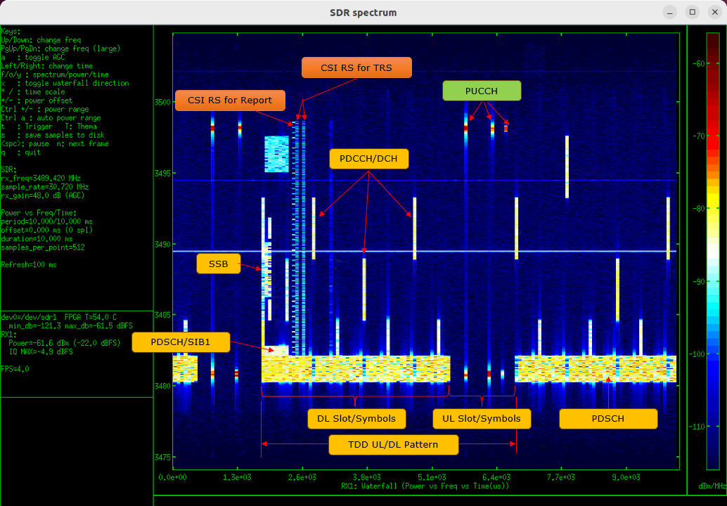
Image captured by Amarisoft sdr_spectrum
Other form of imagination can be as follows. If you can plot this kind of image for each of the symbols in your brain, you are ready to go with the real configuration and test.
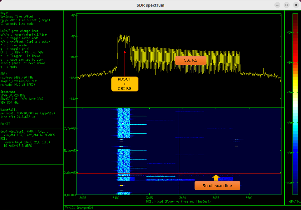
Image captured by Amarisoft sdr_spectrum
Test Setup
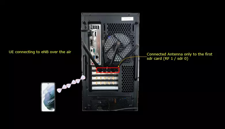
Test setup for this tutorial is as shown below. This is just for low layer testing, you may not need any complicated IP layer setup.
- SIM Card used in this tutorial is the one delivered with the system as it is.
- If you want to change the configuration, The tutorial Configuration Guide would help
Key Configuration Parameters
Followings are important configuration parameters for this tutorial. You may click on the items for the descriptions from Amarisoft documents.
- csi_report_config : In this link, you can find the descriptions for all the parameters below.
- resource_for_channel_measurement
- csi_im_resources_for_interference
- report_config_type
- period
- report_quantity
- codebook_config: In this link, you can find the descriptions for all the parameters below.
- non_pmi_port_indication
- cqi_table
- subband_size
- pdcch
- pdsch
- tci_states: In this link, you can find the descriptions for all the parameters below.
- tci_state_id
- qcl_type1
- reference_signal
- ssb_index
- csi_rs_index
- qcl_type
- ssb_pos_bitmap
- csi_rs
- nzp_csi_rs_resource : In this link, you can find the descriptions for all the parameters below.
- csi_rs_id
- n_ports
- frequency_domain_allocation
- cdm_type
- density
- first_symb
- first_symb2
- rb_start
- l_crb
- period
- offset
- qcl_info_periodic_csi_rs
- csi_im_resource : In this link, you can find the descriptions for all the parameters below.
- csi_im_id
- pattern
- subcarrier_location
- symbol_location
- rb_start
- l_crb
- period
- offset
- zp_csi_rs_resource : In this link, you can find the descriptions for all the parameters below.
- csi_rs_id
- n_ports
- frequency_domain_allocation
- cdm_type
- density
- first_symb
- first_symb2
- rb_start
- l_crb
- period
- offset
- nzp_csi_rs_resource_set : In this link, you can find the descriptions for all the parameters below.
- csi_rs_set_id
- nzp_csi_rs_resources
- repetition
- trs_info
- csi_im_resource_set : In this link, you can find the descriptions for all the parameters below.
- csi_im_set_id
- csi_im_resources
- resource_auto : In this link, you can find the descriptions for all the parameters below.
- nzp_csi_rs_period
- n_ports
- trs_presence
- trs_period
- exclude_slot_sib1
- exclude_slot_ssb
- power_control_offset
- dl_bwp_list
Reference Configuration : Auto CSI Configuration
Configuration
Since this is a reference test, I just used a default reference configuration gnb-sa.cfg.

In the configuration file, you can select any specific tdd pattern with the parameter NR_TDD_CONFIG. To apply TDD configuration, you first need to configure the duplex mode (NR_TDD) to 1 (TDD). And then I set NR_TDD_CONFIG to 2 which is one of default sample configuration provided by Amarisoft sample configuration. And I set the channel bandwidth (NR_BANDWIDTH) to 20Mhz and 2x2 MIMO (N_ANTENNA_DL = 2)
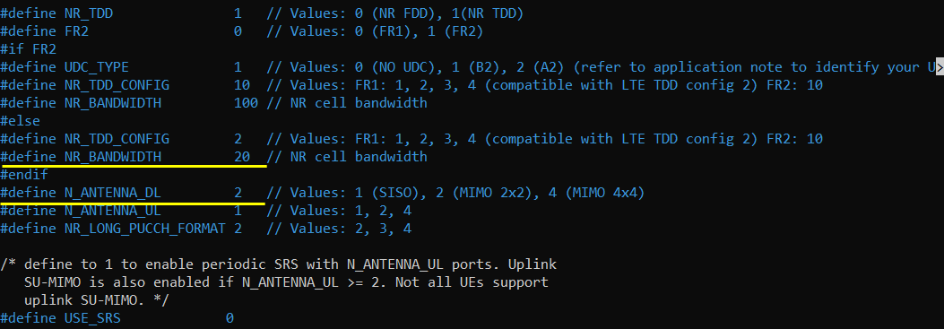
Here you can enable csi_rs simply by sing resource_auto and specify a couple of simple setting like nzp_csi_rs_period and trs_presence in stead of configuring all the complicated individual csi resources and csi resource sets.
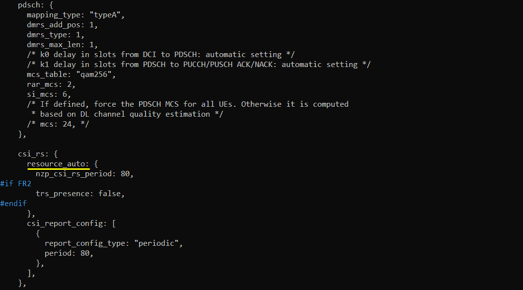
Following table shows an example of csi configuration that just configures a single set of TRS and one csi-report. You would notice how simple it get with auto CSI configuration.
|
Configuration without AutoCSI |
Configuration with AutoCSI |
| This is the configuration in gnb-sa.cfg before AutoCSI feature is supported | This is the configuration in gnb-sa.cfg after AutoCSI feature is supported |
|
csi_rs: { nzp_csi_rs_resource: [ { csi_rs_id: 0, #if N_ANTENNA_DL == 1 n_ports: 1, frequency_domain_allocation: "row2", bitmap: "100000000000", cdm_type: "no_cdm", #elif N_ANTENNA_DL == 2 n_ports: 2, frequency_domain_allocation: "other", bitmap: "100000", cdm_type: "fd_cdm2", #elif N_ANTENNA_DL == 4 n_ports: 4, frequency_domain_allocation: "row4", bitmap: "100", cdm_type: "fd_cdm2", #elif N_ANTENNA_DL == 8 n_ports: 8, frequency_domain_allocation: "other", bitmap: "110011", cdm_type: "fd_cdm2", #else #error unsupported number of DL antennas #endif density: 1, first_symb: 4, rb_start: 0, l_crb: -1, /* -1 means from rb_start to the end of the bandwidth */ power_control_offset: 0, /* dB */ power_control_offset_ss: 0, /* dB */ period: 80, offset: 1, /* != 0 to avoid collision with SSB */ qcl_info_periodic_csi_rs: 0, }, #if FR2 == 0 #define USE_TRS #endif #ifdef USE_TRS /* TRS : period of 40 ms, slots 1 & 2, symbols 4 and 8 */ { csi_rs_id: 1, n_ports: 1, frequency_domain_allocation: "row1", bitmap: "0001", cdm_type: "no_cdm", density: 3, first_symb: 4, rb_start: 0, l_crb: -1, /* -1 means from rb_start to the end of the bandwidth */ power_control_offset: 0, /* dB */ power_control_offset_ss: 0, /* dB */ period: 40, offset: 11, qcl_info_periodic_csi_rs: 0, }, { csi_rs_id: 2, n_ports: 1, frequency_domain_allocation: "row1", bitmap: "0001", cdm_type: "no_cdm", density: 3, first_symb: 8, rb_start: 0, l_crb: -1, /* -1 means from rb_start to the end of the bandwidth */ power_control_offset: 0, /* dB */ power_control_offset_ss: 0, /* dB */ period: 40, offset: 11, qcl_info_periodic_csi_rs: 0, }, { csi_rs_id: 3, n_ports: 1, frequency_domain_allocation: "row1", bitmap: "0001", cdm_type: "no_cdm", density: 3, first_symb: 4, rb_start: 0, l_crb: -1, /* -1 means from rb_start to the end of the bandwidth */ power_control_offset: 0, /* dB */ power_control_offset_ss: 0, /* dB */ period: 40, offset: 12, qcl_info_periodic_csi_rs: 0, }, { csi_rs_id: 4, n_ports: 1, frequency_domain_allocation: "row1", bitmap: "0001", cdm_type: "no_cdm", density: 3, first_symb: 8, rb_start: 0, l_crb: -1, /* -1 means from rb_start to the end of the bandwidth */ power_control_offset: 0, /* dB */ power_control_offset_ss: 0, /* dB */ period: 40, offset: 12, qcl_info_periodic_csi_rs: 0, }, #endif ], nzp_csi_rs_resource_set: [ { csi_rs_set_id: 0, nzp_csi_rs_resources: [ 0 ], repetition: false, }, #ifdef USE_TRS { csi_rs_set_id: 1, nzp_csi_rs_resources: [ 1, 2, 3, 4 ], repetition: false, trs_info: true, }, #endif ],
csi_im_resource: [ { csi_im_id: 0, pattern: 1, subcarrier_location: 8, symbol_location: 8, rb_start: 0, l_crb: -1, /* -1 means from rb_start to the end of the bandwidth */ period: 80, offset: 1, /* != 0 to avoid collision with SSB */ }, ], csi_im_resource_set: [ { csi_im_set_id: 0, csi_im_resources: [ 0 ], } ], /* ZP CSI-RS to set the CSI-IM REs to zero */ zp_csi_rs_resource: [ { csi_rs_id: 0, frequency_domain_allocation: "row4", bitmap: "100", n_ports: 4, cdm_type: "fd_cdm2", first_symb: 8, density: 1, rb_start: 0, l_crb: -1, /* -1 means from rb_start to the end of the bandwidth */ period: 80, offset: 1, }, ], p_zp_csi_rs_resource_set: [ { zp_csi_rs_resources: [ 0 ], }, ],
csi_resource_config: [ { csi_rsc_config_id: 0, nzp_csi_rs_resource_set_list: [ 0 ], resource_type: "periodic", }, { csi_rsc_config_id: 1, csi_im_resource_set_list: [ 0 ], resource_type: "periodic", }, #ifdef USE_TRS { csi_rsc_config_id: 2, nzp_csi_rs_resource_set_list: [ 1 ], resource_type: "periodic", }, #endif ], csi_report_config: [ { resources_for_channel_measurement: 0, csi_im_resources_for_interference: 1, report_config_type: "periodic", period: 80, report_quantity: "CRI_RI_PMI_CQI", #if N_ANTENNA_DL > 1 codebook_config: { codebook_type: "type1", sub_type: "typeI_SinglePanel", #if N_ANTENNA_DL == 2 #elif N_ANTENNA_DL == 4 n1: 2, n2: 1, codebook_mode: 1, #elif N_ANTENNA_DL == 8 n1: 4, n2: 1, codebook_mode: 1, #endif }, #endif cqi_table: 2, subband_size: "value1", }, ], }, |
csi_rs: { resource_auto: { nzp_csi_rs_period: 80, #if FR2 trs_presence: false, #endif }, csi_report_config: [ { report_config_type: "periodic", period: 80, }, ], },
|
Log Analysis
This is just for showing the association between the configuration shown above and IE (Information Elements) in RRC.
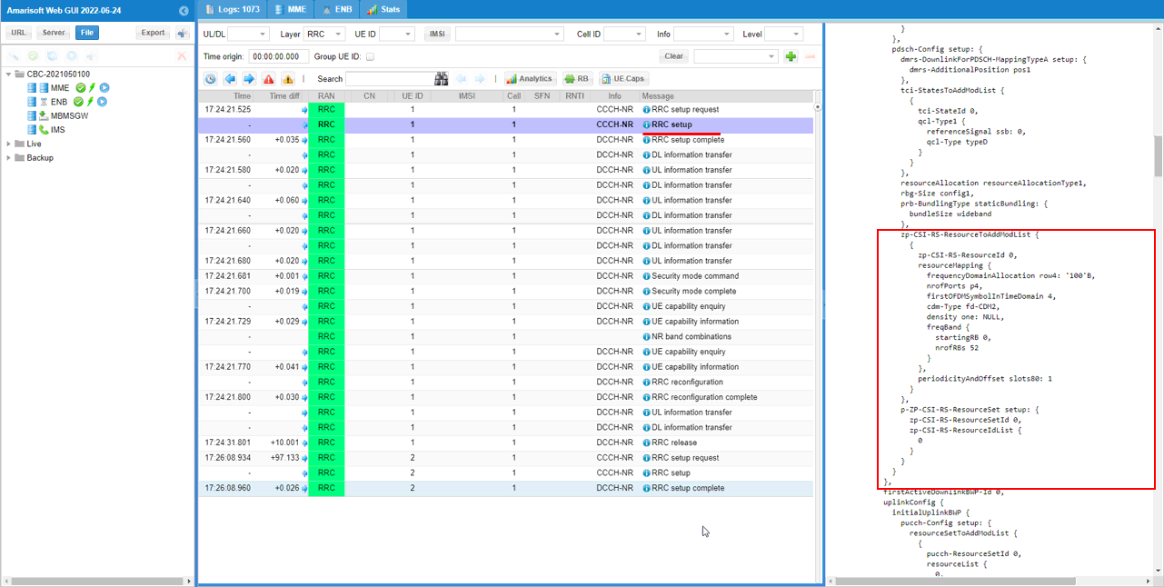
First check out zp-CSI-RS-ResourceToAddModList in pdsch-Config. All the detailed IEs within the configuration was set automatically by the resource_auto configuration parameter.
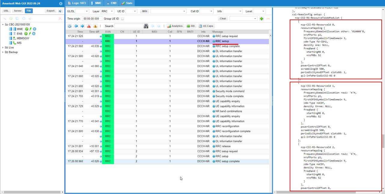
Then you can check out nzp-CSI-RS-ResourceToAddModList in csi-MeasConfig IE. Here you see 5 csi resources are configured.
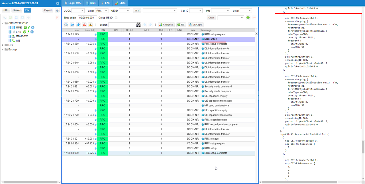
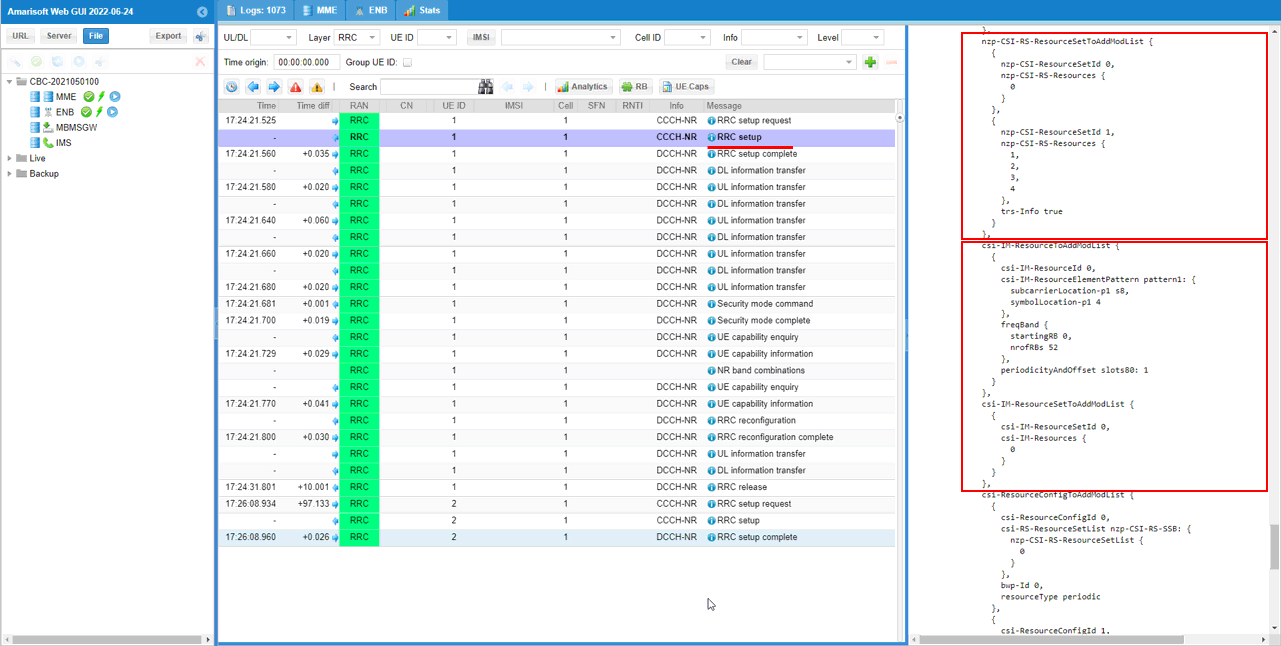
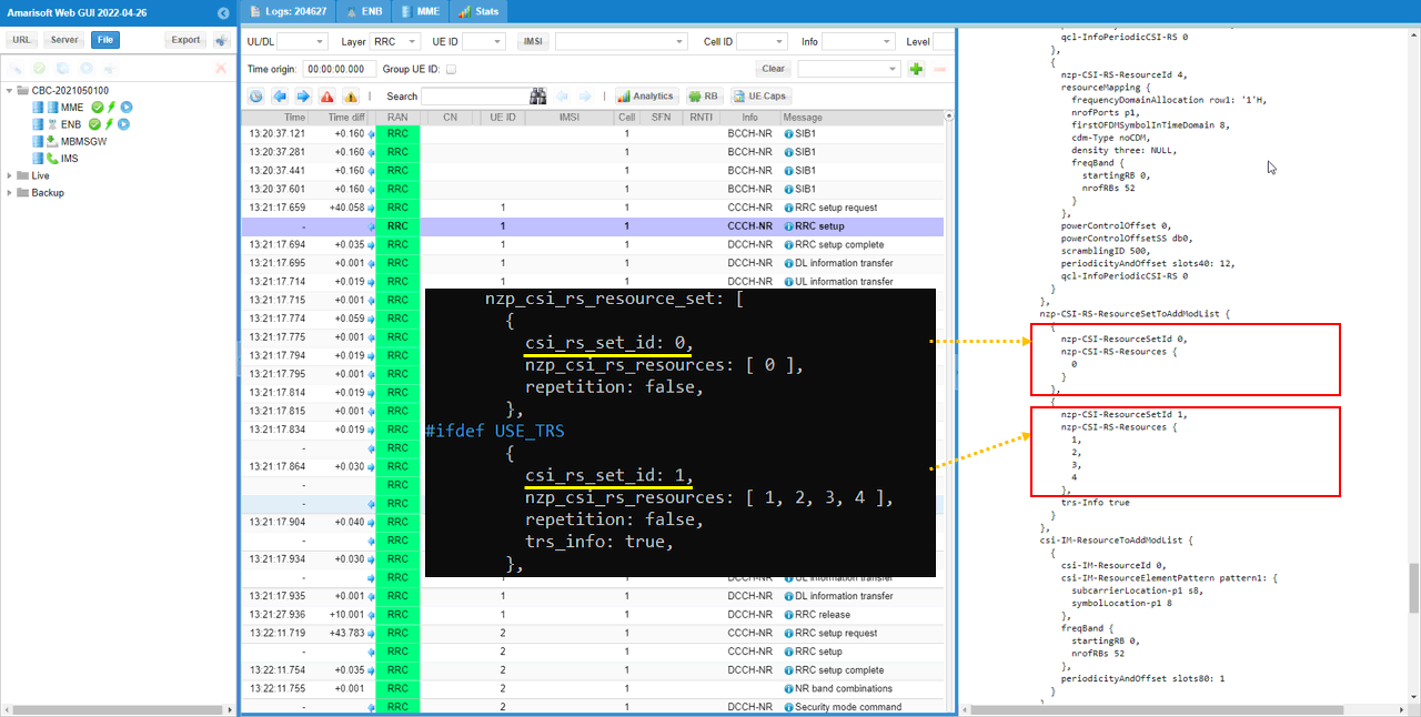
Then by checking nzp-CSI-RS-ResourceSetToAddModList, you can figure out how the 5 csi resources configured above are grouped together for a specific purpose. Here you see nzp-CSI-RS 1,2,3,4 are grouped into a single set and is used for trs. nzp-CSI-RS 0 will be used for CSI report.
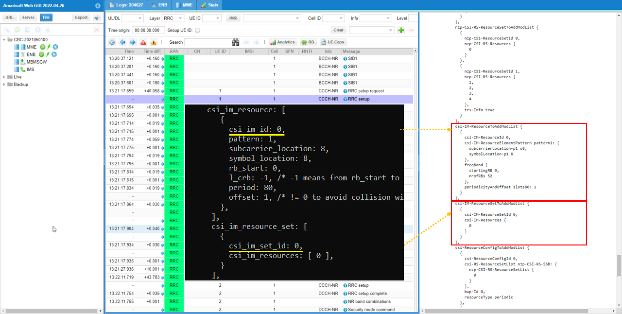
Also here you see csi-IM-ResourceToAddModList is configured. This is a special CSI resources for interference measurement.
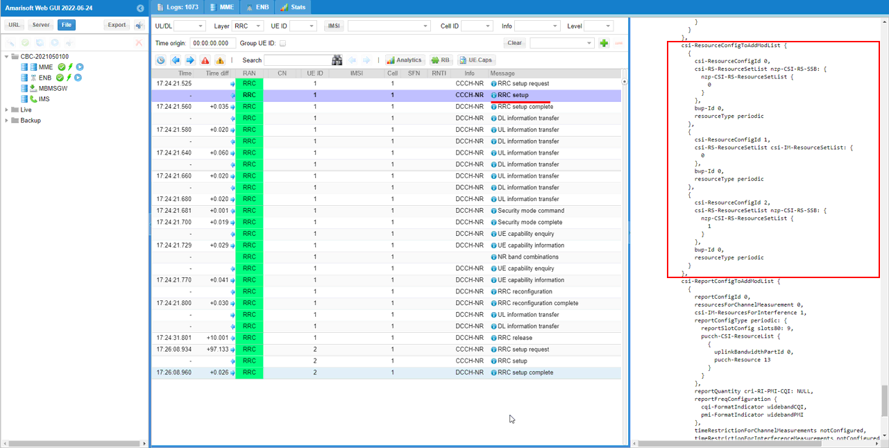
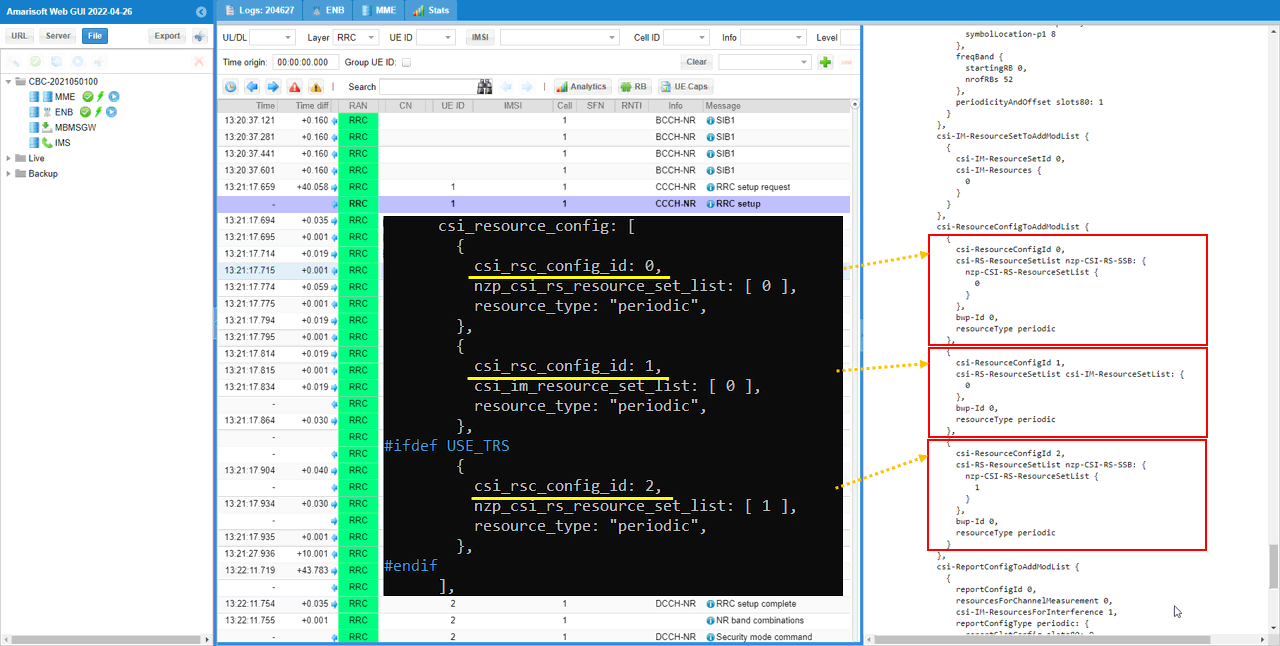
By checking csi-ResourceConfigToAddModList, you can figure out how each CSI resport group of csi rs (i.e, csi resource set assigned for CSI report) is configured for the report. Here you see CSI Resource Set 0 and CSI IM Resource Set 0 are configured for periodic Report. In addition to this, SSB is also configured for periodic report.
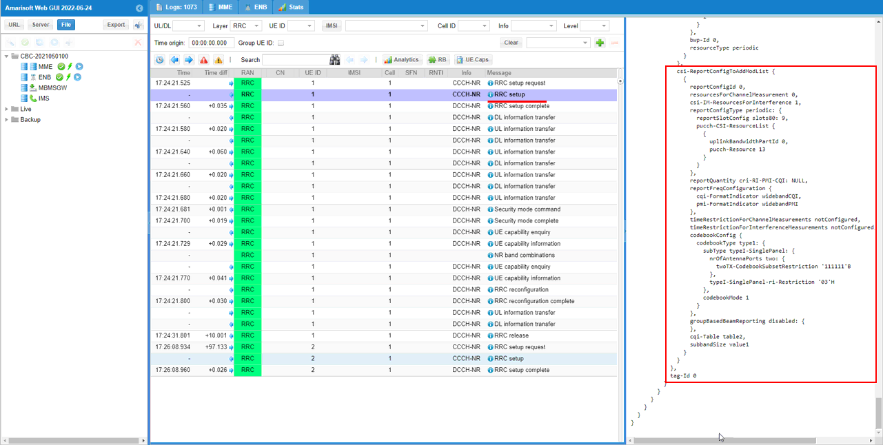
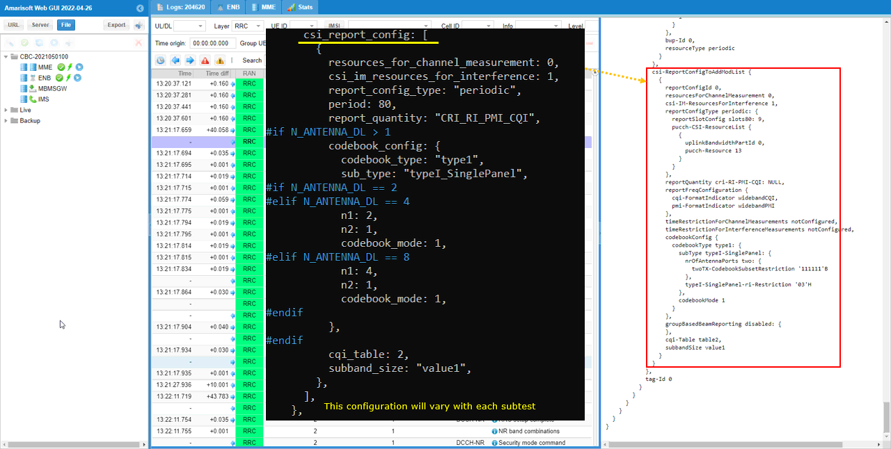
As the last step, csi-ReportConfigToAddModList is configured for the report configuation based on all the configurations specified above.
Test 1 : Periodic CSI Report
In this test, I will show you how to configure manually the periodic CSI report and validate it. Obviously manual configuration is much more complicated than the auto configuration, but you will have full flexibility for the configuration.
Configuration
The configuration shown here is common configuration for all the subtests belonging to Test 1 and I will not show this configuration repeatedly for every subtest.
I have used gnb-sa-rq-ri-pmi-cqi.cfg which is copied and modified from gnb-sa.cfg

I am using the default mme, ims config as shown below.

In gnb-sa-rq-ri-pmi-cqi.cfg, it is configured as follows.
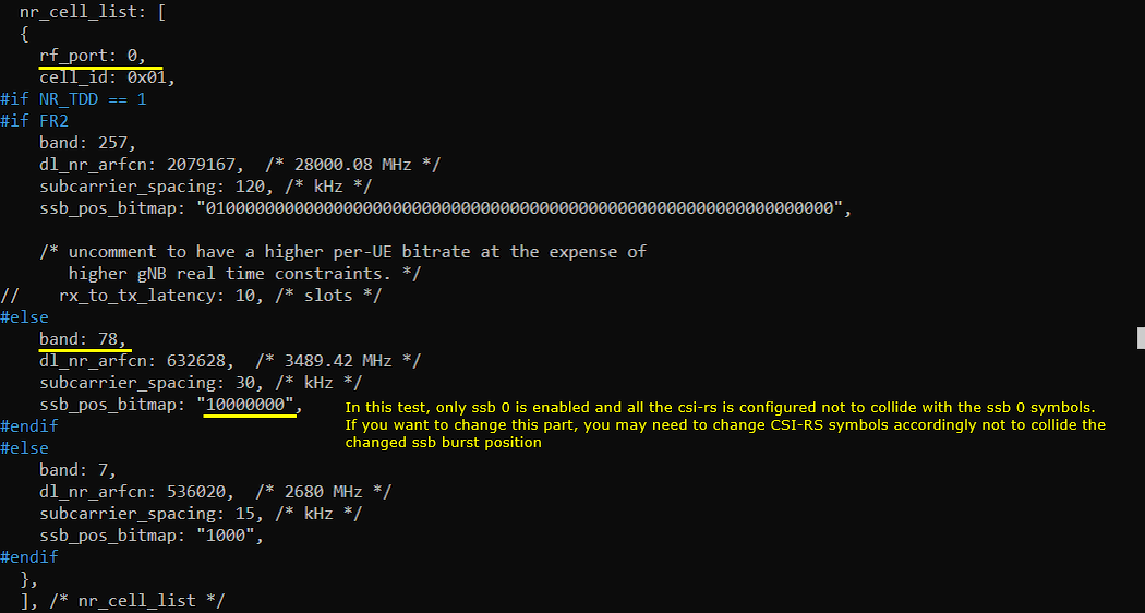
In the configuration file, you can select any specific tdd pattern with the parameter NR_TDD_CONFIG. To apply TDD configuration, you first need to configure the duplex mode (NR_TDD) to 1 (TDD). And then I set NR_TDD_CONFIG to 2 which is one of default sample configuration provided by Amarisoft sample configuration. And I set the channel bandwidth (NR_BANDWIDTH) to 20Mhz and 2x2 MIMO (N_ANTENNA_DL = 2)

Here the band is set to n78 which is a TDD band. The important part is ssb_pos_bitmap. In this test, only ssb 0 is enabled and all the csi-rs is configured not to collide with the ssb 0 symbols. If you want to change this part, you may need to change CSI-RS symbols accordingly not to collide the changed ssb burst position.
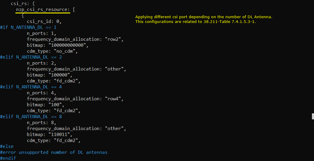
Here comes the difficult parts which is about configuring all the physical resources. The first physical resource is configured for CSI report. Applying different csi port depending on the number of DL antenna. This configurations are related to 38.211-Table 7.4.1.5.3-1.
One important thing for you to pay attention to especially for TDD is to make it sure that this configuration should fall into DL slots/symbols in TDD UL/DL common configuration and should not collide with other physical resources like SSB, PDCCH or PDSCH DMRS etc.

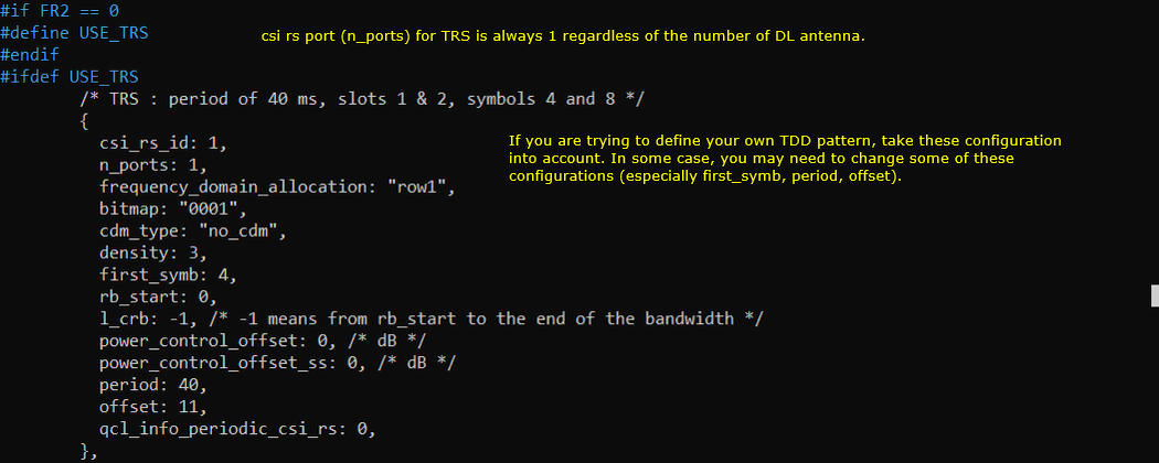
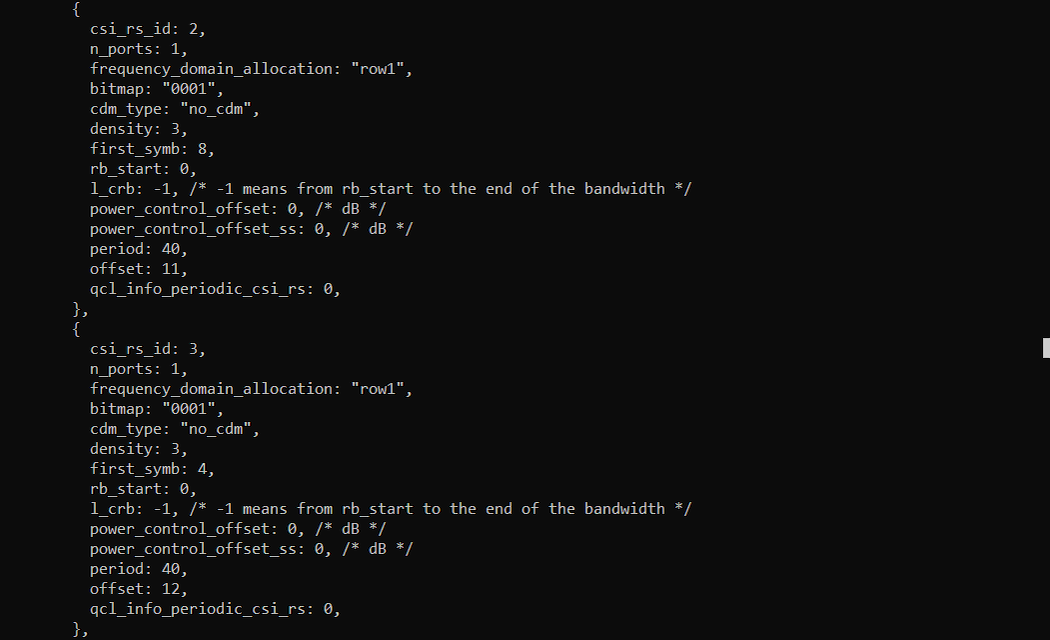
Now four csi resources are configured to define TRS in such a way to meet 3GPP requirement.
Again One important thing for you to pay attention to especially for TDD is to make it sure that this configuration should fall into DL slots/symbols in TDD UL/DL common configuration and should not collide with other physical resources like SSB, PDCCH or PDSCH DMRS etc.
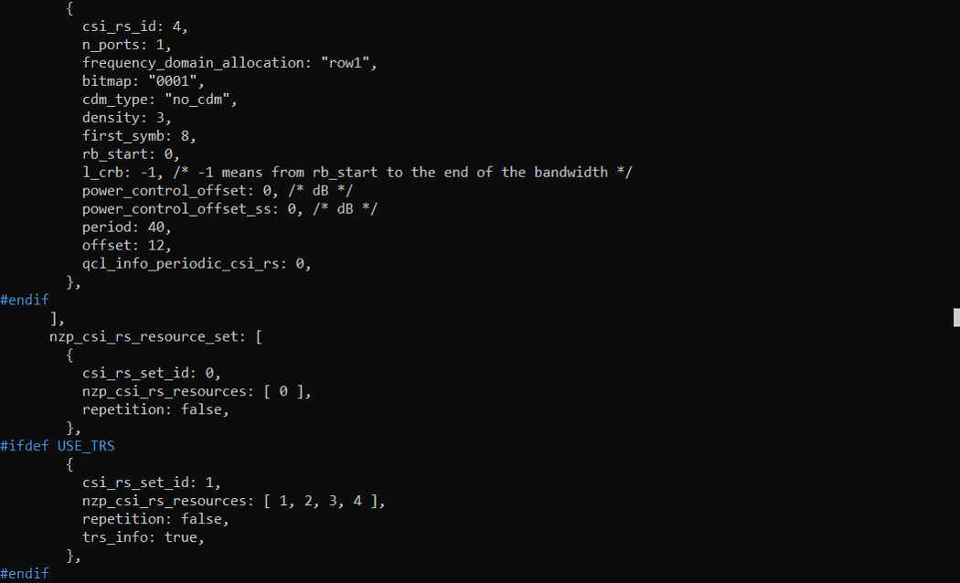
Next step is to group the nzp csi resource defined above as per usage (purpose). This is done by nzp_csi_rs_resource_set configuration parameter. Here two group (two sets) are defined. The first group is the one with only one elements in nzp_csi_rs_resources array which will be used for CSI report and the second group (set) is the one with 4 elements in nzp_csi_rs_resources array which will be used for TRS.

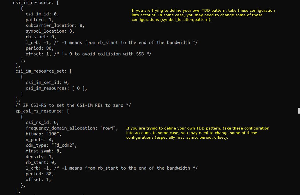
Last part of the csi resource configuration in this test is for the resources for interference measurement, which are IM resources and ZP CSI resources shown here. CSI IM is configured by the parameter csi_im_resources and ZP CSI resources is configured by zp_csi_rs_resources. Again and Again, one important thing for you to pay attention to especially for TDD is to make it sure that this configuration should fall into DL slots/symbols in TDD UL/DL common configuration and should not collide with other physical resources like SSB, PDCCH or PDSCH DMRS etc.
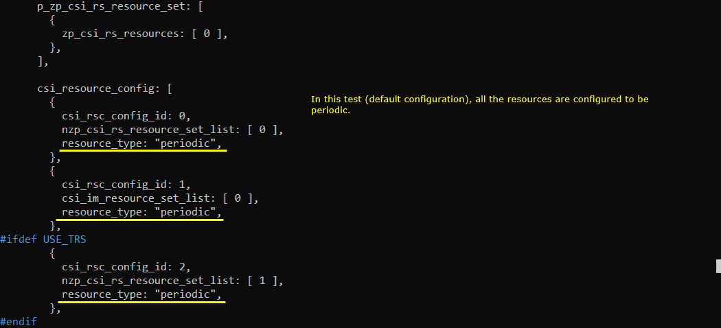
One step above the physical resource grouping (i.e, csi rs resource set) is csi resource config (csi_resource_config) which groups the resource sets (it is a kind of super group with the restpect of csi resource) and assign a specific type (resource_type) to the group. In this test, all the resources sets are set to periodic.
Log Analysis
This is just for showing the association between the configuration shown above and IE (Information Elements) in RRC.
In this specific test, it is not so important but it is worth noting that at least one tci-state gets configured in RRC even when you didn't configure anything in configuration file. Here, you see one tci-State assciated with ssb 0 is configured in tci-StatesToAddModList of pdsch-Config. Regarding the TCI/QCL, you may refer to this note.
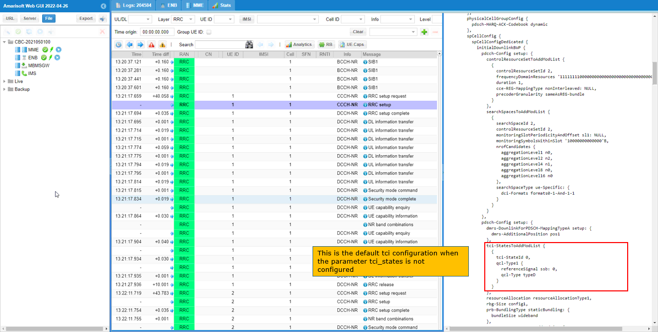
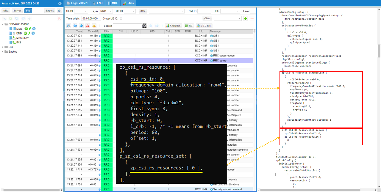
Now let's take a look into csi configuration that is under pdsch-Config. It is zp-CSI-RS-ResourceToAddModList IE in pdsch-Config. This IE is set by the configuration parameter zp_csi_rs_resource and p_zp_csi_resource_set as shown here.
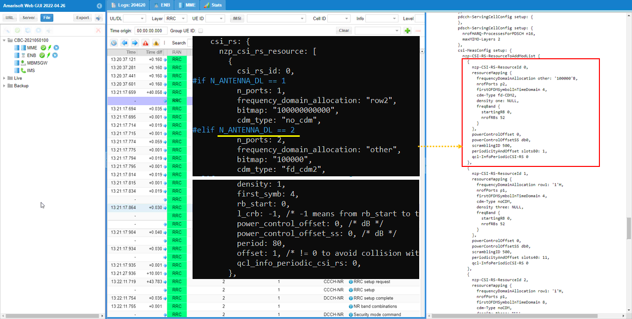
Next, check how each of the nzp CSI RS is configured in RRC. These configurations are set in csi-MeasConfig. The individual nzp CSI RS Resource are configured in nzp-CSI-RS-ResourceToAddModList. This is the first nzp-CSI-RS-Resource which will be used for CSI Report.
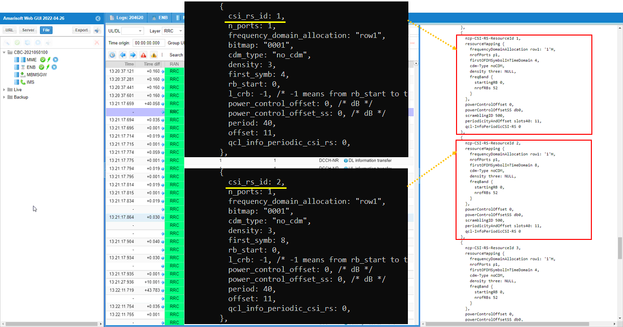
Next comes with two additional csi rs resouces that will be used for TRS.
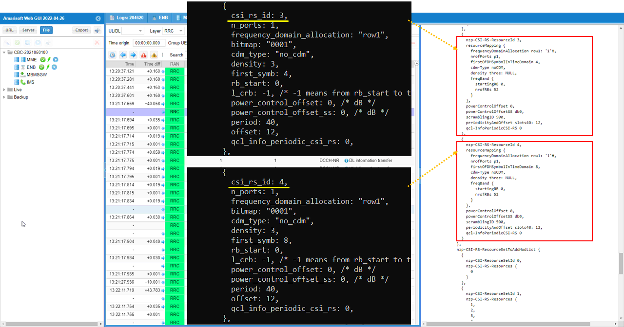
Next comes with additional two additional csi rs resouces that will be used for TRS.
Once all the physical resources for CSI RS are configured, a step high level grouping happens by nzp-CSI-RS-ResourcesSetToAddModList. In this test, two group are formed. The first group is made up of only one nzp-CSI-RS-Resource and the second group is made up of 4 nzp-CSI-RS-Resources.
Next is to check on the configuration for interference measurement. You can check it with csi-IM-ResourceToAddModList IE and csi-IM-ResourceSetToAddModList IE. These IEs are configured by csi_im_resource and csi_im_resource_set respectively.
With all the CSI Resource Sets configured, we need to check on the next level grouping which is CSI Resource Config. It is configured in csi-ResourceConfigAddModList in RRC which is configured by csi_resource_config in Amarisoft gNB configuration.
In this specific example, all of the csi resource set is configured to be periodic.
Now let's check on what is sitting at the top of CSI configuration hierarchy which is csi-ReportConfigAddModList. This configuration is set by the configuration parameter csi_report_config. In this specific test, periodic CSI report for cri-RI-PMI-CQI is configured.
Sub Test 1 : RI-PMI-CQI
The purpose of this Sub Test is just to change report quantity to RI-PMI-CQI while all other configurations are set same as in the main test.
I have used gnb-sa-rq-ri-pmi-cqi.cfg which is copied and modified from gnb-sa.cfg

Configuratio is set as follows. Just report_quantity is changed to "CRI_RI_PMI_CQI" and All other configuration not shown here is assumed to be same as the configuration in Common Configuration of Test 1
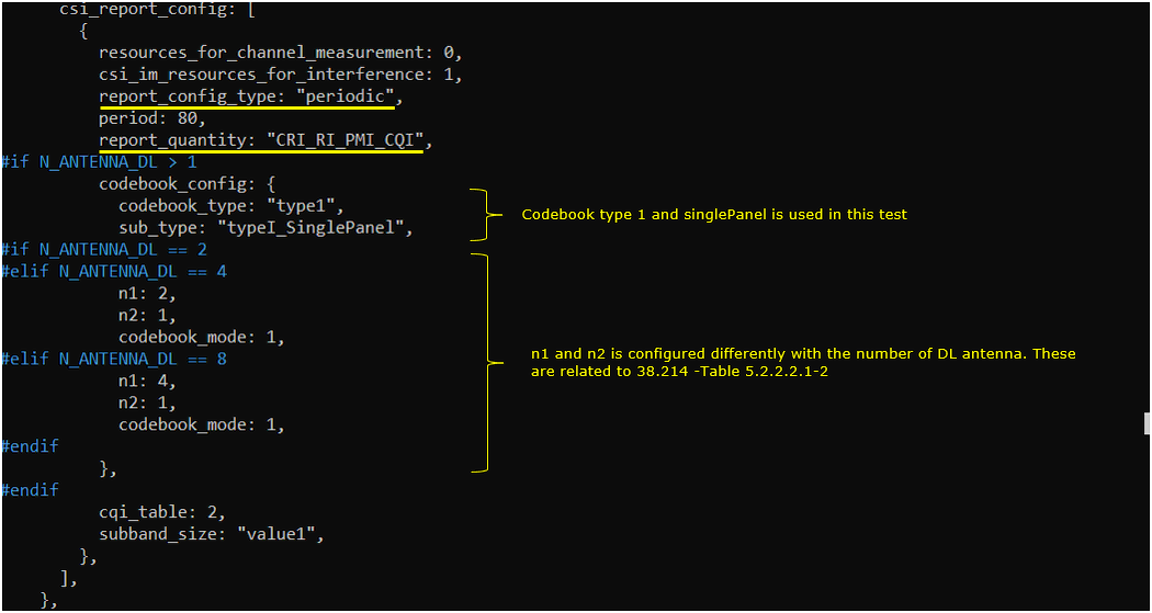
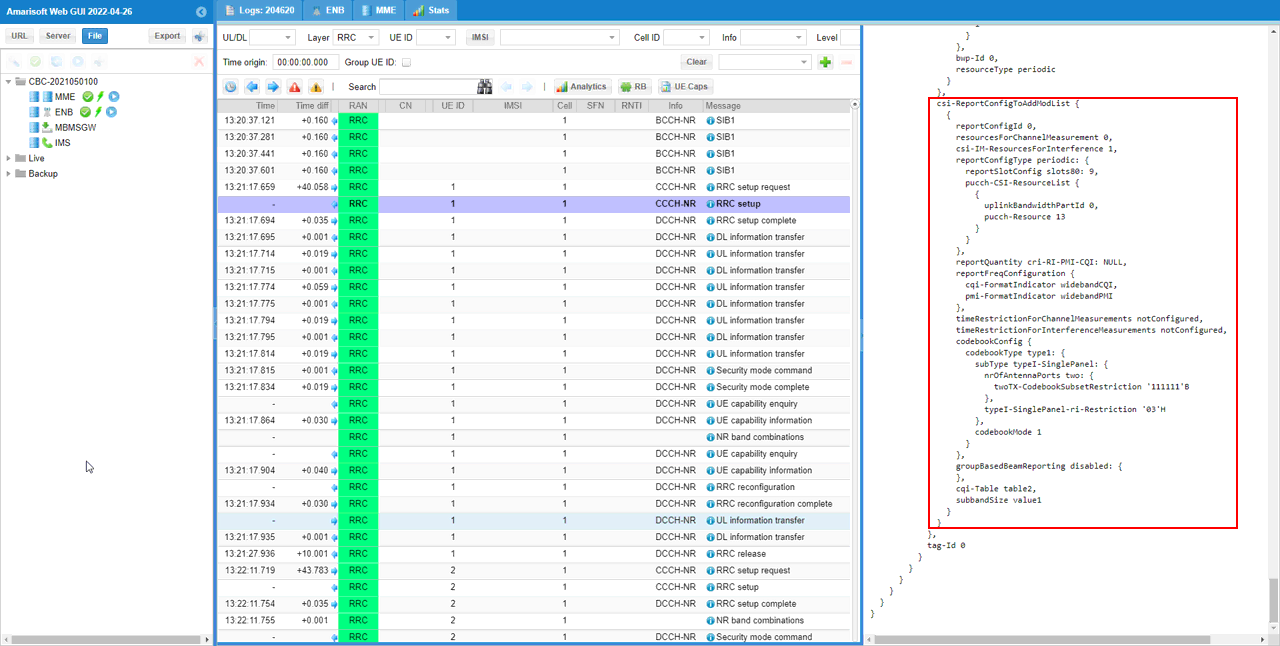
This configuration will be reflected in RRC as shown below. Check out reportQuantity of csi-ReportConfigToAddModList IE and confirm that it is set to cri-RI-PMI-CQI as set in the configuration file.
Perform the test.
Start LTE service (gNB) and run 'cell phy' and 'cell' command, then everything is configured as you intended.

Before powering on UE, run 't' command first. You can run this command anytime, but I would recommend you to run it before powering on UE to collect the trace log from the very beginning of the attach process.

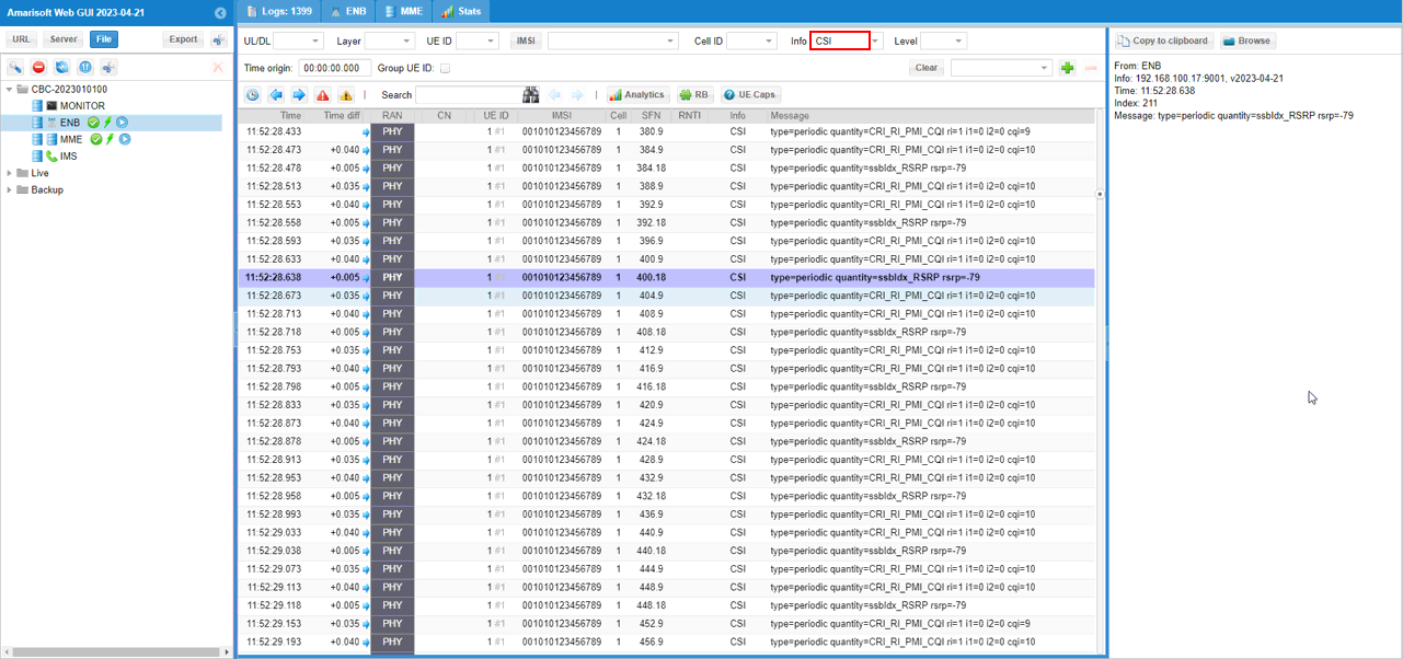
Check PUCCH with CSI Report. First thing to check is that the gNB is getting csi report with the period set in the configuration file.
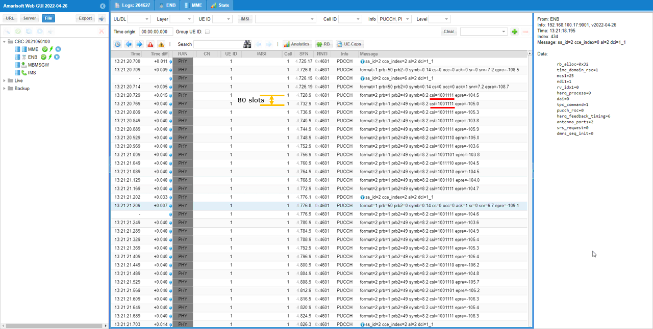
Sub Test 2 : RI-CQI
The purpose of this Sub Test is just to change report quantity to RI-CQI while all other configurations are set same as in the main test.
I have used gnb-sa-rq-ri-cqi.cfg which is copied and modified from gnb-sa.cfg

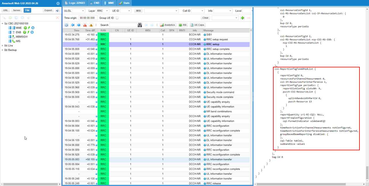
Configuratio is set as follows. Just report_quantity is changed to "CRI_RI_CQI" and All other configuration not shown here is assumed to be same as the configuration in Common Configuration of Test 1

this configuration will be reflected in RRC as shown below. Check out reportQuantity of csi-ReportConfigToAddModList IE and confirm that it is set to cri-RI-CQI as set in the configuration file.
Perform the test.
Start LTE service (gNB) and run 'cell phy' and 'cell' command, then everything is configured as you intended.

Before powering on UE, run 't' command first. You can run this command anytime, but I would recommend you to run it before powering on UE to collect the trace log from the very beginning of the attach process.

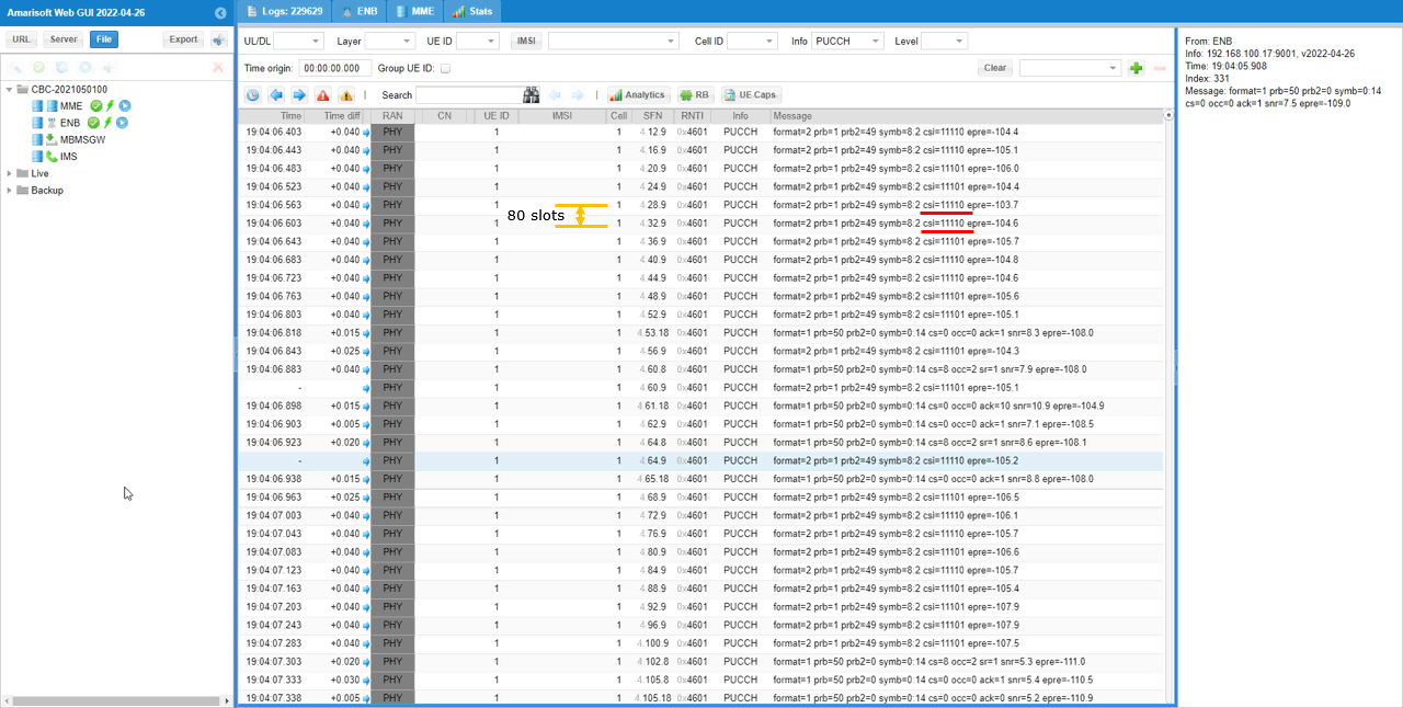
Check PUCCH with CSI Report. First thing to check is that the gNB is getting csi report with the period set in the configuration file.
Sub Test 3 : RI-CQI with non-PMI-PortIndication
The purpose of this Sub Test is just to change report quantity to RI-CQI with non-PMI-PortIndication while all other configurations are set same as in the main test.
I have used gnb-sa-rq-ri-cqi-non-pmi.cfg which is copied and modified from gnb-sa.cfg

Configuratio is set as follows. In this case, report_quantity is changed to "CRI_RI_CQI" and non_pmi_port_indication is set. All other configuration not shown here is assumed to be same as the configuration in Common Configuration of Test 1
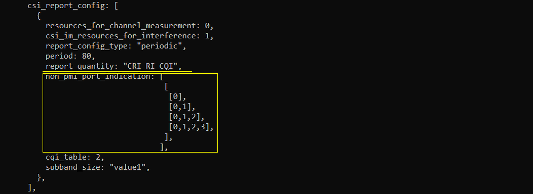
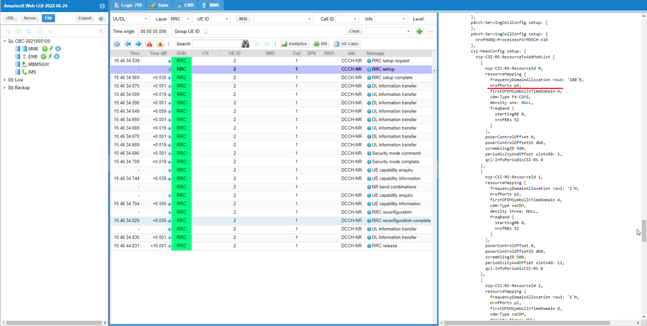
this configuration will be reflected in RRC as shown below. The main purpose of this test is about RI report. So it would be good to check that nrofPorts is configured to multiple ports so that RI report become meaninful.
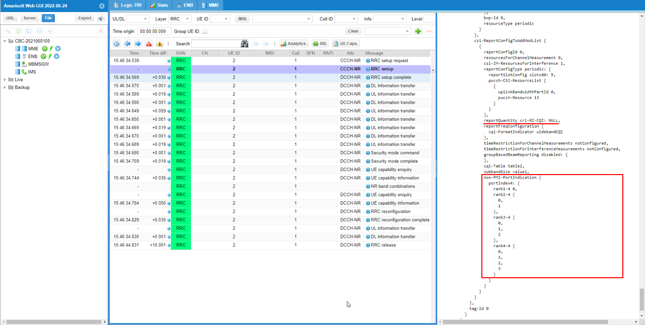
Check out reportQuantity of csi-ReportConfigToAddModList IE and confirm that it is set to cri-RI-PMI-CQI and non-PMI-PortIndication as set in the configuration file
Perform the test.
Start LTE service (gNB) and run 'cell phy' and 'cell' command, then everything is configured as you intended.

Before powering on UE, run 't' command first. You can run this command anytime, but I would recommend you to run it before powering on UE to collect the trace log from the very beginning of the attach process.

Check PUCCH with CSI Report. First thing to check is that the gNB is getting csi report with the period set in the configuration file.
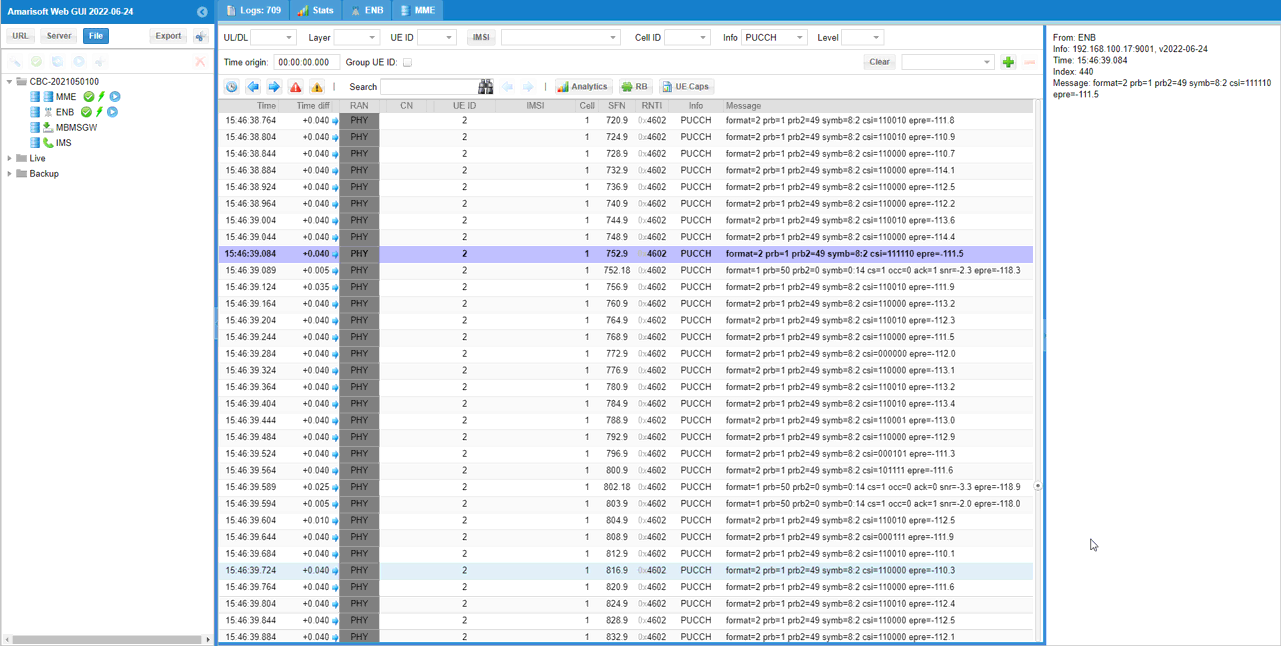
Sub Test 4 : RSRP
The purpose of this Sub Test is just to change report quantity to RSRP while all other configurations are set same as in the main test.
I have used gnb-sa-rq-rsrp.cfg which is copied and modified from gnb-sa.cfg

Configuratio is set as follows. Just report_quantity is changed to "CRI_RSRP" and All other configuration not shown here is assumed to be same as the configuration in Common Configuration of Test 1

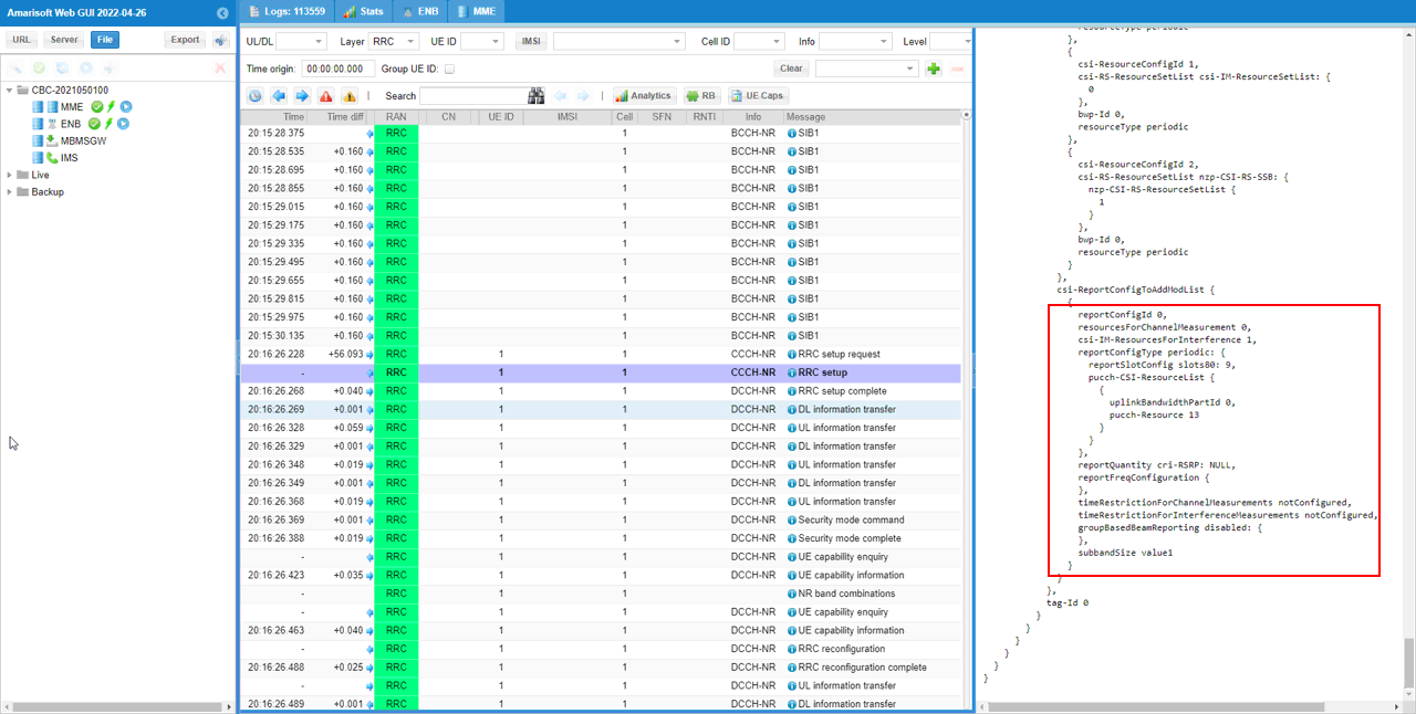
this configuration will be reflected in RRC as shown below.
Check out reportQuantity of csi-ReportConfigToAddModList IE and confirm that it is set to cri-RSRP.
Perform the test.
Start LTE service (gNB) and run 'cell phy' and 'cell' command, then everything is configured as you intended.

Before powering on UE, run 't' command first. You can run this command anytime, but I would recommend you to run it before powering on UE to collect the trace log from the very beginning of the attach process.

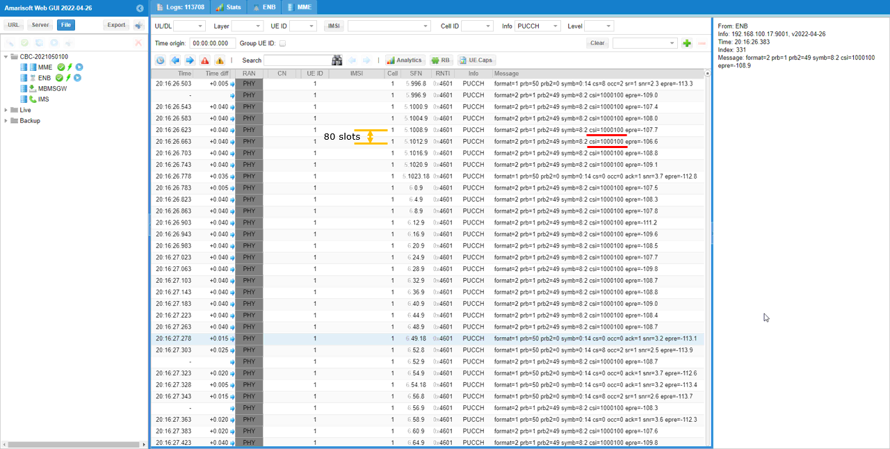
Check PUCCH with CSI Report. First thing to check is that the gNB is getting csi report with the period set in the configuration file.
Sub Test 5 : RI-PMI-CQI with ri-restriction
The purpose of this Sub Test is just to change report quantity to RI-PMI-CQI with manually configured ri-restriction bits while all other configurations are set same as in the main test.
I have used gnb-sa-rq-ri-pmi-cqi-ri-restrict.cfg which is copied and modified from gnb-sa.cfg

Configuratio is set as follows. All other configuration not shown here is assumed to be same as the configuration in Common Configuration of Test 1.
In the configuration file, you can select any specific tdd pattern with the parameter NR_TDD_CONFIG. To apply TDD configuration, you first need to configure the duplex mode (NR_TDD) to 1 (TDD). And then I set NR_TDD_CONFIG to 2 which is one of default sample configuration provided by Amarisoft sample configuration. And I set the channel bandwidth (NR_BANDWIDTH) to 20Mhz and 2x2 MIMO (N_ANTENNA_DL = 2)

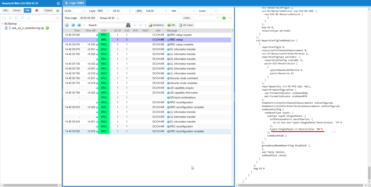
In this test, report_quantity is set to CRI_RI_PMI_CQI as in the first example, but ri_restriction is changed to other value.
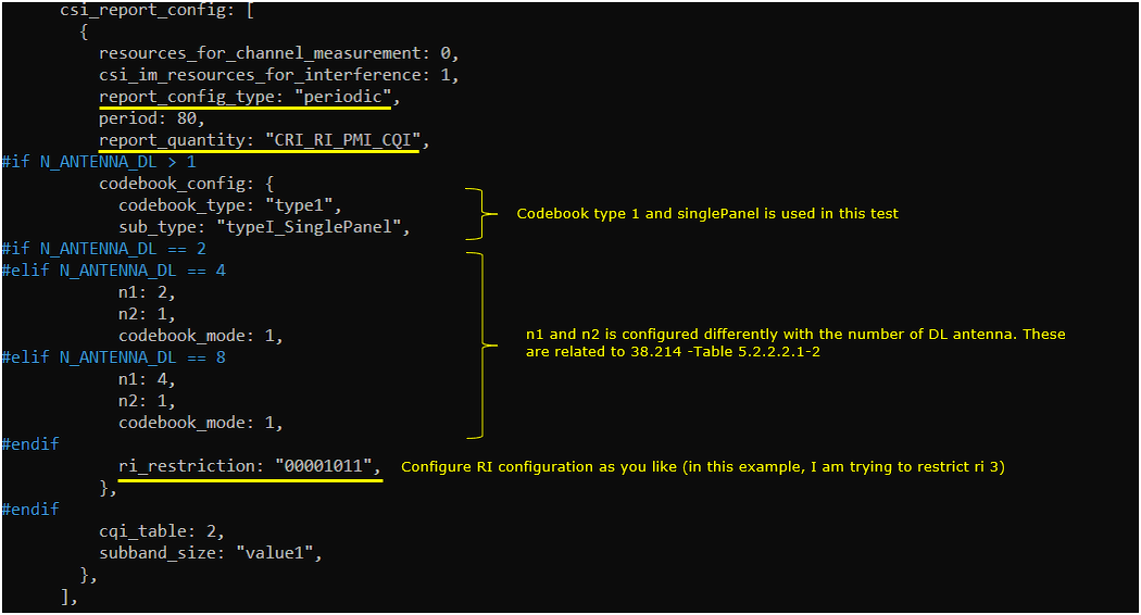
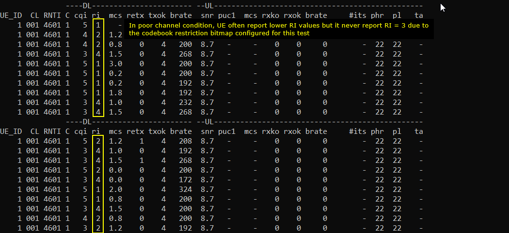
In this test, I need to change radio link quality up and down to see if I am getting RI values based on the restriction set in the configuration. So I extended inactivity_timer so that I can have enough time to play with radio link quality changes

this configuration will be reflected in RRC as shown below.
(
Check out reportQuantity of csi-ReportConfigToAddModList IE and confirm that it is set to cri-RI-PMI-CQI and the typeI-SinglePanel-ri-Restriction is set as you assigned in the configuration file.
Perform the test.
Start LTE service (gNB) and run 'cell phy' and 'cell' command, then everything is configured as you intended.

Power on UE and let it attached in good channel condition. You may get max ri report as shown below.

Degrade the downlink channel condition. You may degrade the downlink channel quality in different ways, but using tx_gain on callbox would be the simplest way to do it (If you are not familiar with usage of tx_gain, refer to this tutorial). You would get the result as shown below.
Sub Test 6 : ssb-RSRP
When you want CSI report for RSRP, you can set a regular CSI RS to be a reference channel for the measurement or you can set SSB to be the reference channel. The Sub Test 4 is the case where the regular CSI RS is used for RSRP reference. This is the case where SSB is used for RSRP reference.
I have used gnb-sa-rsset-1ssb.cfg which is copied and modified from gnb-sa.cfg

Configuratio is set as follows. All other configuration not shown here is assumed to be same as the configuration in Common Configuration of Test 1.
In the configuration file, you can select any specific tdd pattern with the parameter NR_TDD_CONFIG. To apply TDD configuration, you first need to configure the duplex mode (NR_TDD) to 1 (TDD). And then I set NR_TDD_CONFIG to 2 which is one of default sample configuration provided by Amarisoft sample configuration. And I set the channel bandwidth (NR_BANDWIDTH) to 20Mhz and 2x2 MIMO (N_ANTENNA_DL = 2)

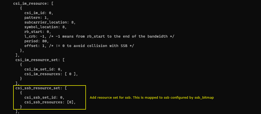
Since we want to use SSB as reference signal for RSRP measurement in this test, we need to configure csi_ssb_resource_set. (
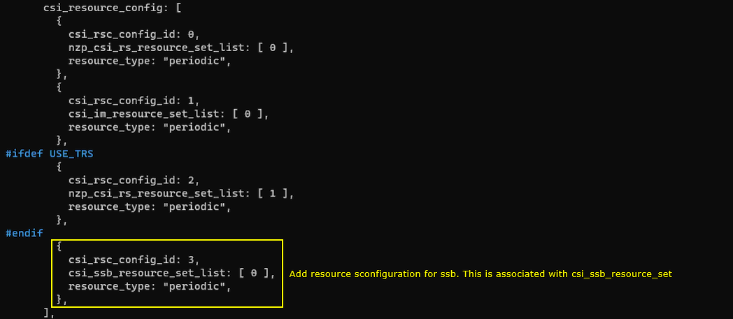
Then register the csi_ssb_resource_set to csi_resource_config.
As final step, apply these configuration to csi_report_config. In this test, I specified two different report configuration. The first one is for CRI_RI_PMI_CQI based on NZP CSI RS. I just left the default configuration as it is.
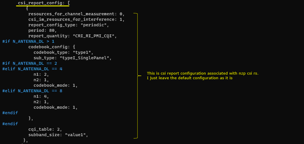
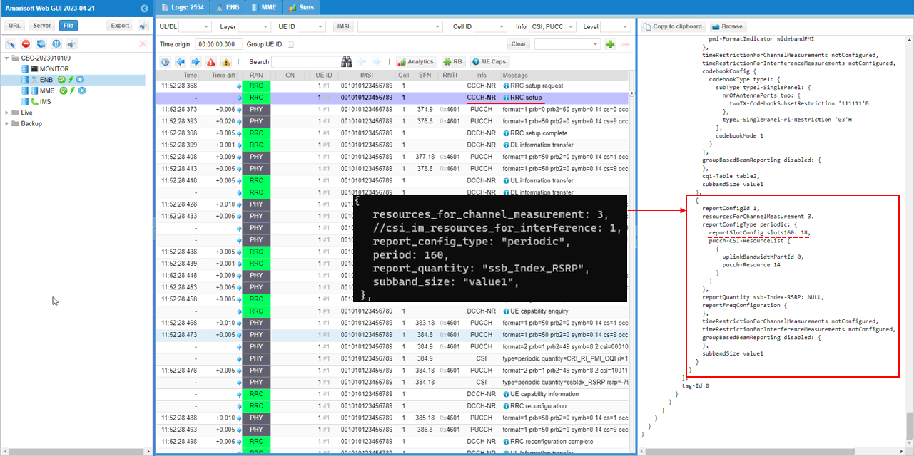
As the second configuration for CSI Report, I added another report configuration with the report_quantity : "ssb_Index_RSRP". Here resource_for_channel_measurement is set to 3 which corresponds to SSB configuration in our test.

this configuration will be reflected in RRC as shown below.
Since this is all about CSI configuration, go to csi-MeasConfig IE in RRC message.
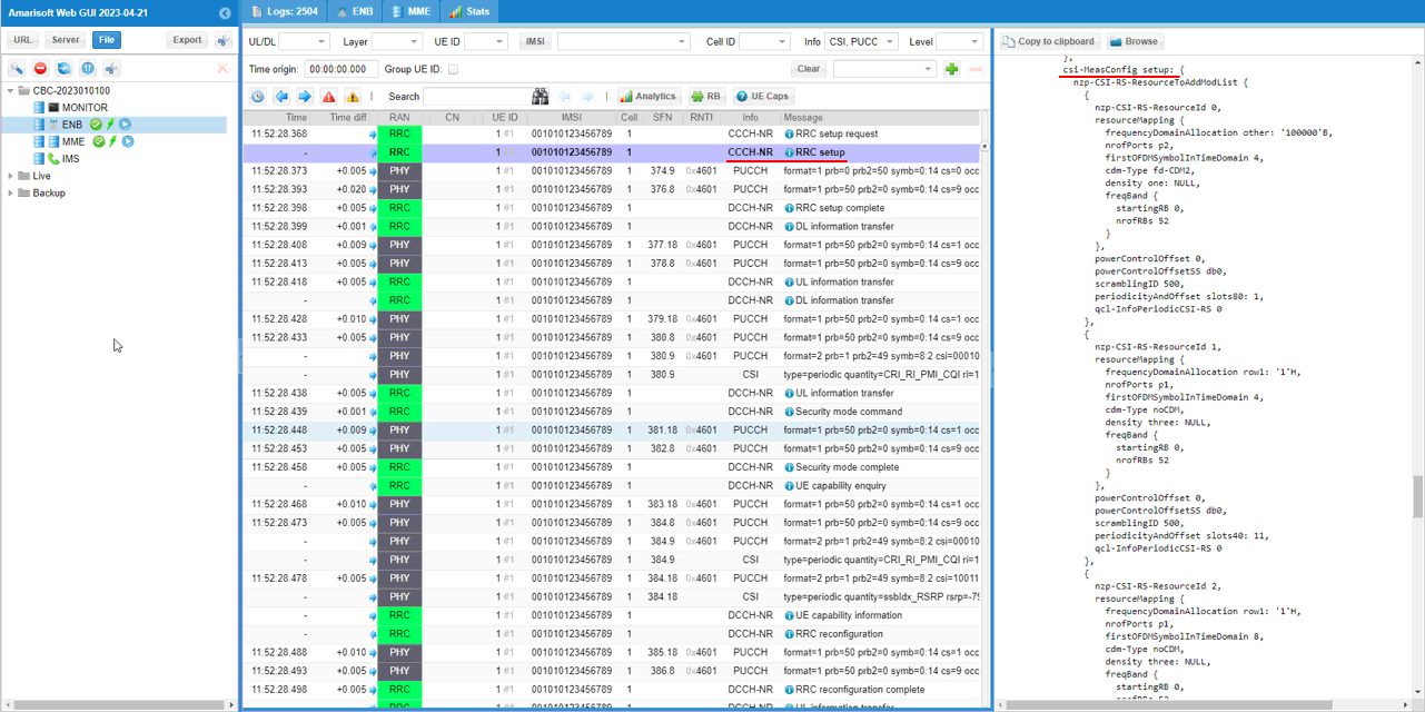
First confirm that SSB is registered to csi-SSB-ResourceSetToAddModList as set in the configuration file.
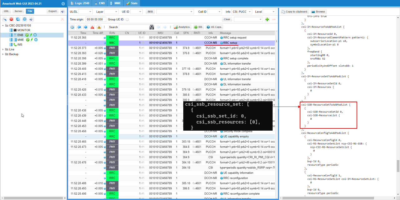
Next check out if the ssb resource set is properly registerred to csi-ResourceConfigToAddModeList as you set in the configuration. Here you see it is registered here as csi-ResourceConfigId 3.
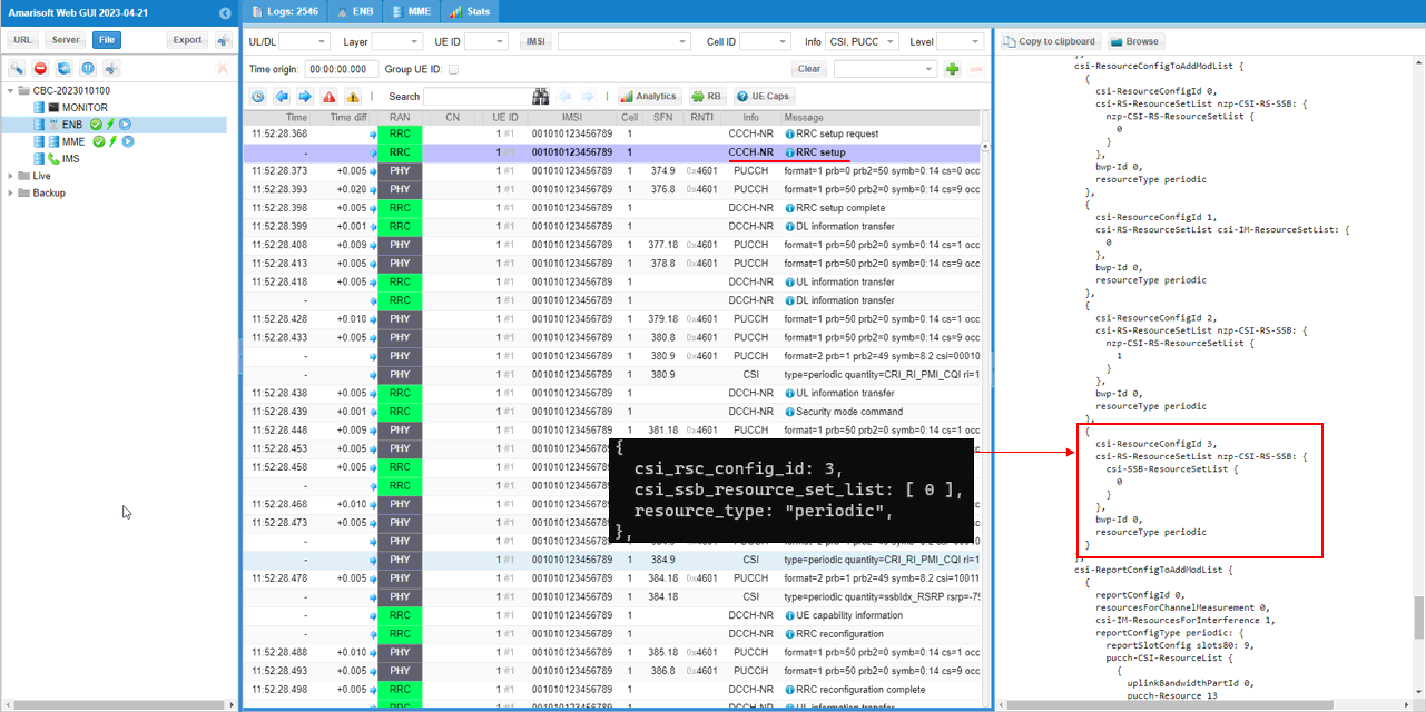
Now for final check. Look into csi-ReportConfigToAddModList to make it sure all the configuration is set as expected. The first report configuration is same as the default configuration which is with reportQuantity csi-RI-PMI-CQI.
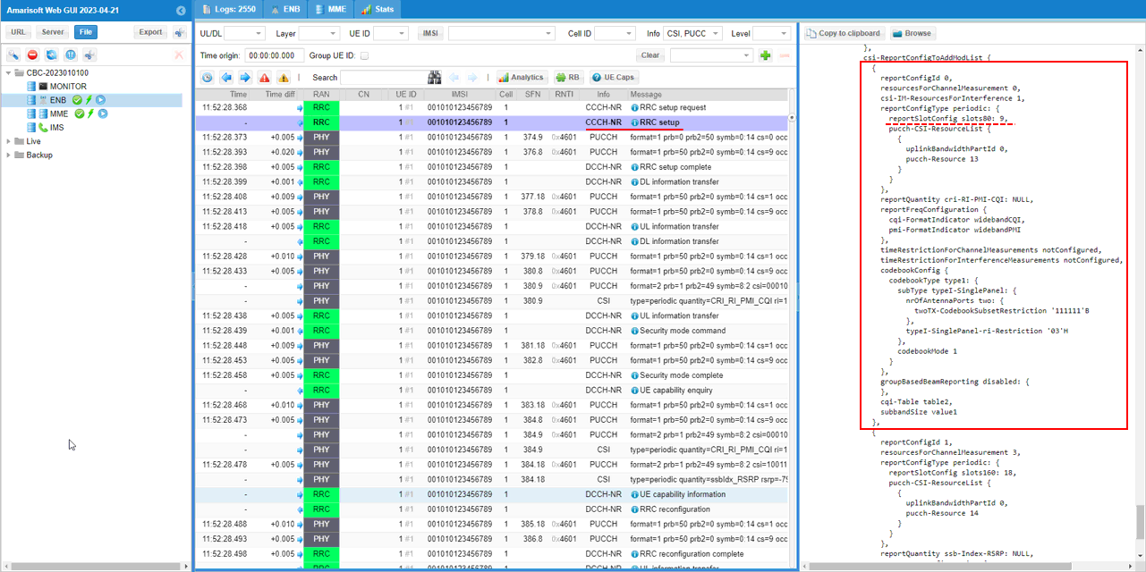
Report configuration for SSB based RSRP is configured as the second item of the report config. As you see here, reportQuantity is set to ssb-Index-RSRP and resourceForChannelMeasurement is set to 3 which is same as csi-ResourceConfigId assigned for SSB resource set.
Perform the test.
Start LTE service (gNB) and run 'cell phy' and 'cell' command, then everything is configured as you intended.

Before powering on UE, run 't' command first. You can run this command anytime, but I would recommend you to run it before powering on UE to collect the trace log from the very beginning of the attach process.

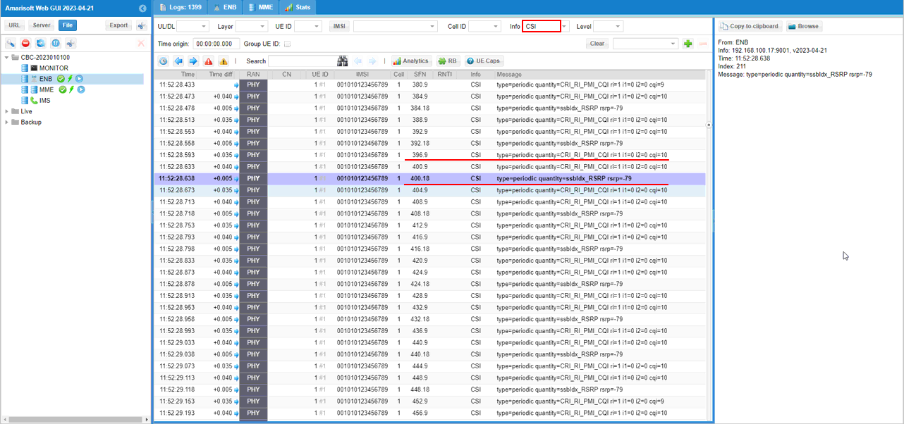
Confirm that you are getting both CRI based CSI report and ssb based CSI Report as shown below. First thing to check is that the gNB is getting csi report with the period set in the configuration file and then check the details of CSI to confirm you get all the components specified in the configuration file. What you need to note here is that you get the two different CSI report. One for CRI_RI_PMI_CQI and another one is for RSRP based on SSB.
Test 2 : Aperiodic CSI Report
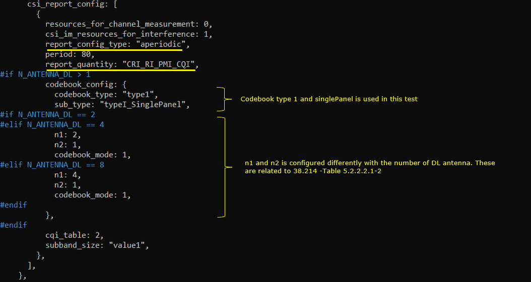
The perpose of this test is to show how to perform Aperiodic CSI report and verify it from the test log. In this test, I configured aperiodic by changing the periodic only in csi_report_config without changing anything csi_resource_config.
I have used gnb-sa-rq-ri-pmi-cqi-aperiodic.cfg which is copied and modified from gnb-sa.cfg

Configuratio is set as follows. All other configuration not shown here is assumed to be same as the configuration in Common Configuration of Test 1. The only difference is that report_config_type in csi_report_config is set to "aperiodic" in this test.
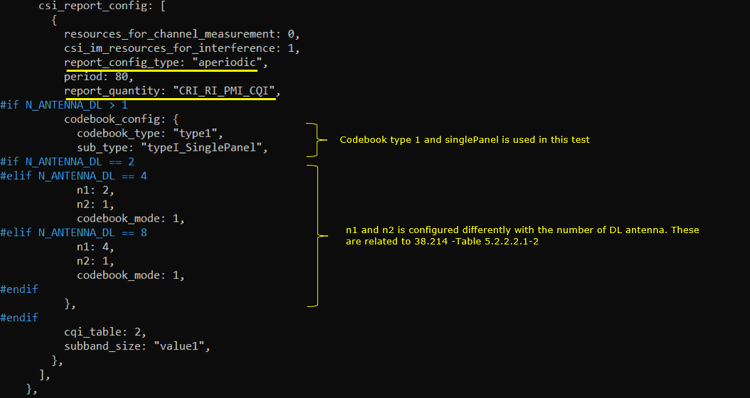
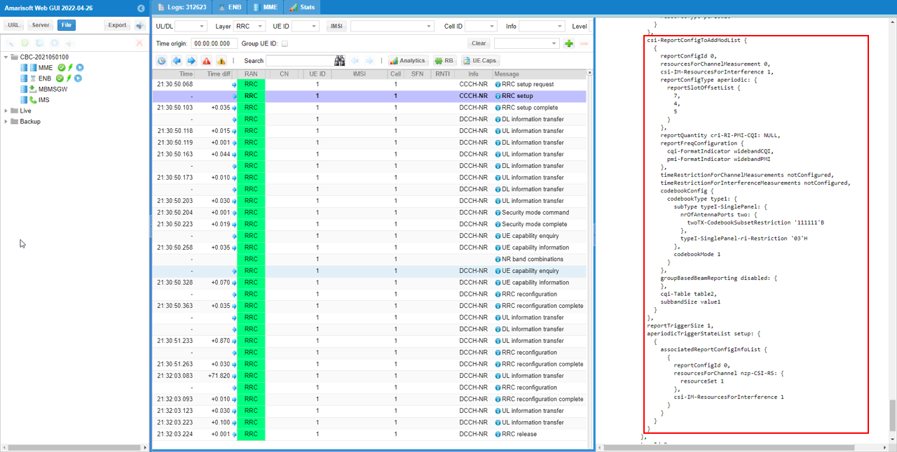
This configuration will be reflected in RRC as shown below. Here you see reportConfigType is set to aperiodic. Important thing to notice is reportSlotOffsetList. These values will be used as k2 value for PUSCH scheduling and these are automatically by Amarisoft gNB.
Perform the test.
Start LTE service (gNB) and run 'cell phy' and 'cell' command, then everything is configured as you intended.

Before powering on UE, run 't' command first. You can run this command anytime, but I would recommend you to run it before powering on UE to collect the trace log from the very beginning of the attach process.

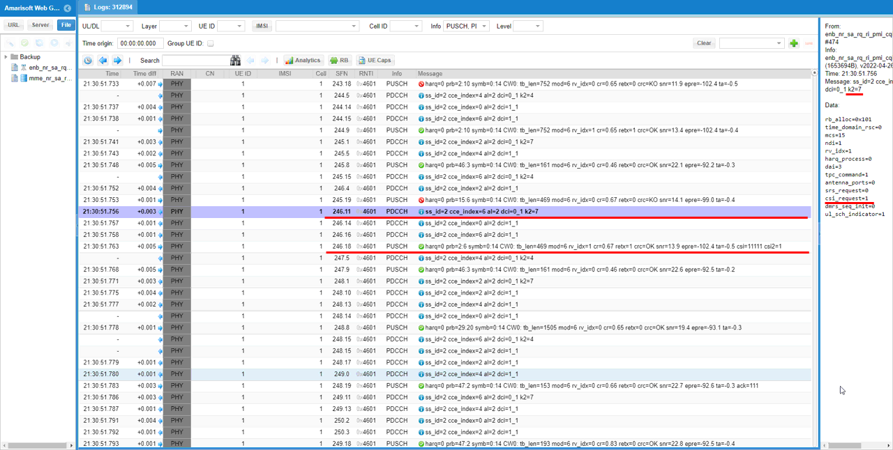
Check PUSCH with CSI Report. Since Aperiodic CSI Request is reported via PUSCH, you need to confirm on both DCI and corresponding PUSCH. In DCI shown here, you see k2 is set to 7 and csi_request is set to 1. Then you see a PUSCH with CSI report value is received after k2 slots after the DCI 0_1.
Test 3 : TCI
This test is to show how to configure TCI(Transmission Configuration Indication) and verify it with the test. There two types of TCI can be configured by 3GPP, one is with pdcch and the other one is with PDSCH ( If you want to get the details of TCI in terms of 3GPP, refer to this note)
I have used gnb-sa-tci-1ssb-1sci.cfg which is copied and modified from gnb-sa.cfg

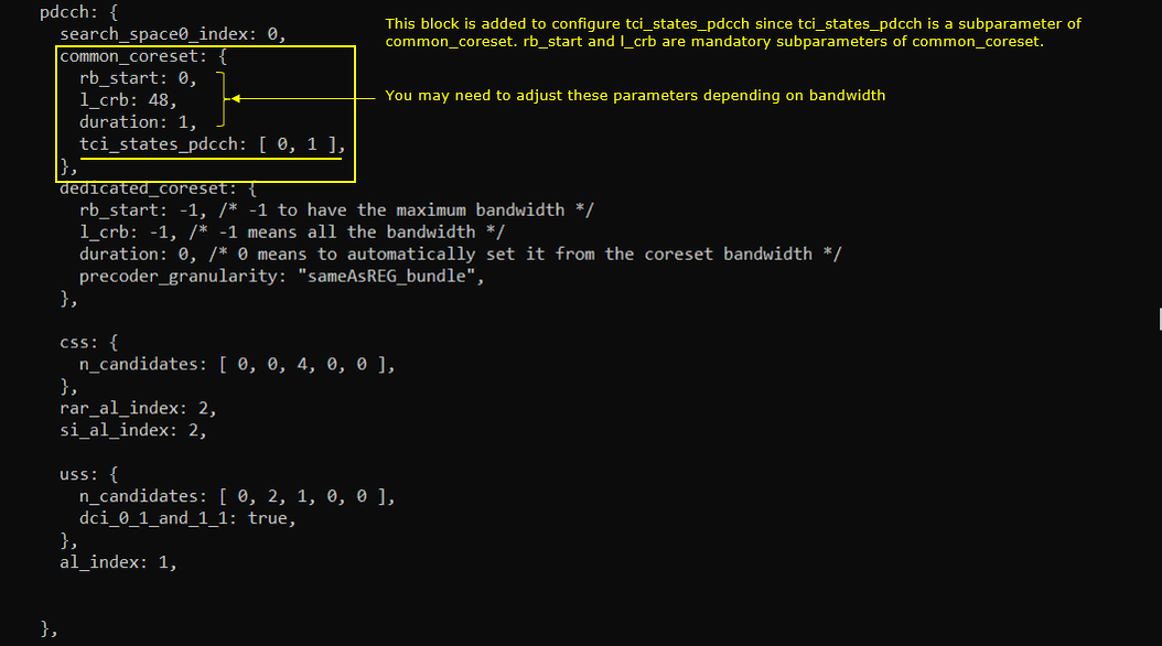
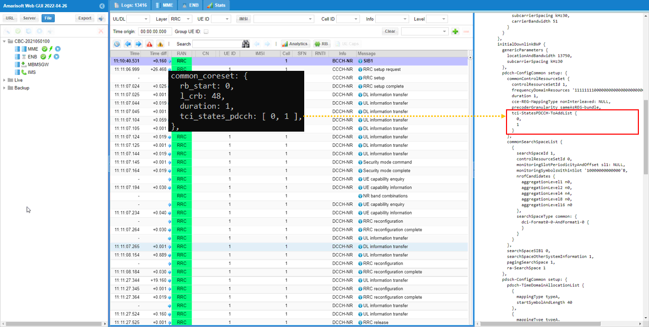
Configuratio is set as follows. TCI for PDCCH is configured by the parameter tci_states_pdcch within common_coreset object. The element number in tci_states_pdcch indicates the tci_state_id specifined in pdsch tci_states. All other configuration not shown here is assumed to be same as the configuration in Common Configuration of Test 1.
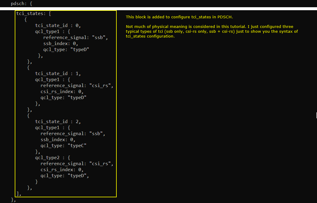
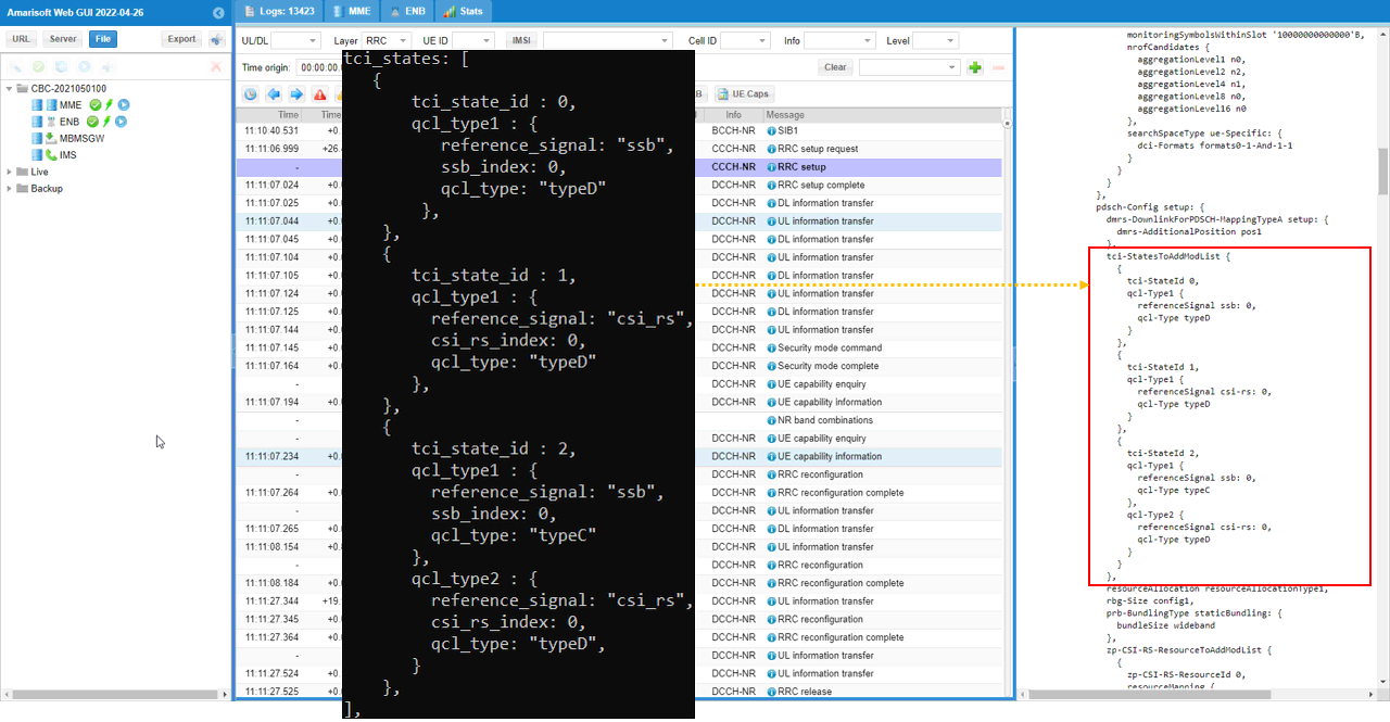
TCI for PDSCH is configured by the parameter tci_states in pdsch configuration. Here I set three tci states. The first tci (tci_state_id 0) is associated with ssb only (ssb 0), the second one is associated with csi_rs only (csi_rs 0) and the third one is associated with both ssb and csi_rs.
csi_report_config is same as in default configuration (i.e, the configuration in Test 1)
This configuration will be reflected in RRC as shown below.
Check out tci-StatesPDCCH-ToAddList in pdcch-ConfigCommon and make it sure that it is configured as you set in the configuration file.
Then check out tci-StatesToAddModList in pdsch-Config IE and see if they are configured as you set in the configuration file.
Perform the test.
Start LTE service (gNB) and run 'cell phy' and 'cell' command, then everything is configured as you intended.

Before powering on UE, run 't' command first. You can run this command anytime, but I would recommend you to run it before powering on UE to collect the trace log from the very beginning of the attach process.

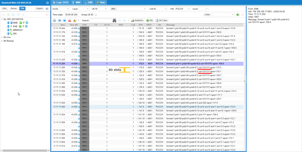
Check PUCCH with CSI Report. Just checking out the gNB logging you only can confirm that the configuration is not causing any fatal problem on UE side and not possible to confirm that UE is really applying the TCI as configured in RRC. On gNB log, just check if you are getting the csi report with the expected interval. If you are using a commercial UE with the very detailed logging capability, you can confirm on whether the UE is properly applying or not from the UE log.
Test 4 : CSI RS p32 - Periodic
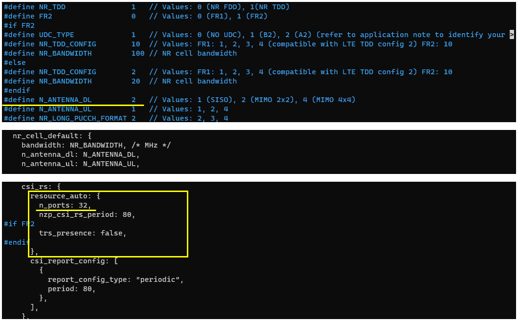
This is an example showing how to configure 32 port CSI RS, but it is not strongly recommended to use this kind of configuration whereas the number of csi-rs port is greater than the number of physical antenna.
I have used gnb-sa-csi-p32.cfg which is copied and modified from gnb-sa.cfg
In the configuration file, you can select any specific tdd pattern with the parameter NR_TDD_CONFIG. To apply TDD configuration, you first need to configure the duplex mode (NR_TDD) to 1 (TDD). And then I set NR_TDD_CONFIG to 2 which is one of default sample configuration provided by Amarisoft sample configuration. And I set the channel bandwidth (NR_BANDWIDTH) to 20Mhz and 2x2 MIMO (N_ANTENNA_DL = 2)
The point here is to set n_ports value to 32 which is much greater than the number of physical antenna. (
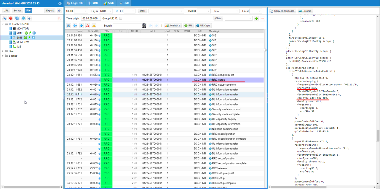
This is the log showing that the csi-rs p32 is configured in signaling message.
Just check if nrofPorts in nzp-CSI-RS-ResourceToAddModList is set as you set in the configuration file and make it sure that it does not cause any problem on UE. This would be just to check if the configuration is accepted by UE without causing any problem. This is not for the performance test.
Test 5 : CSI RS and Physical Antenna Mapping - TRS
This is an example showing how to map the logical antenna port of each CSI RS to physical antenna of Amarisoft gNB antenna. In this example, I will configure a TRS which is made up of 4 CSI-RS and map each of the CSI-RS to two physical antenna as shown below.
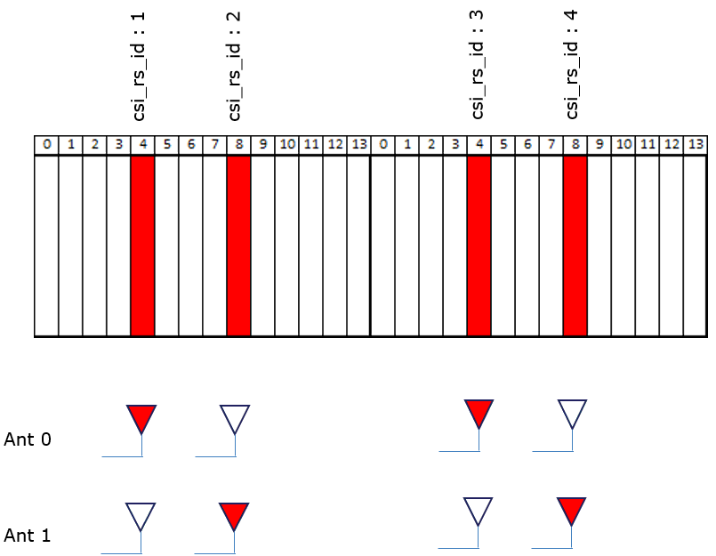
I have used gnb-sa-trs-rs-ant-map.cfg which is copied and modified from gnb-sa-rq-ri-pmi-cqi.cfg which is based on manual configuration for CSI-RS (not auto configuration). Since we need to configure physical antenna mapping for each separate csi rs configuration, we need to configure everything manually.
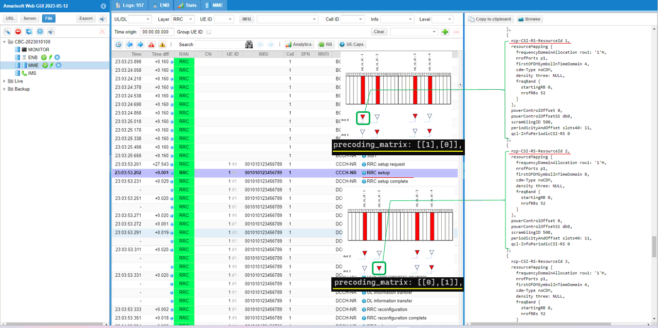
For csi_rs_id: 1, the precoding_matrix is set to [[1], [0]]. Here, the index of the element [1] is 0 (i.e, the first elements (index 0) is set to 1). So the physicall antenna mapped to this csi rs is antenna 0.
For csi_rs_id: 2, the precoding_matrix is set to [[0], [1]]. Here, the index of the element [1] is 1 (i.e, the first elements (index 1) is set to 1). So the physicall antenna mapped to this csi rs is antenna 1.
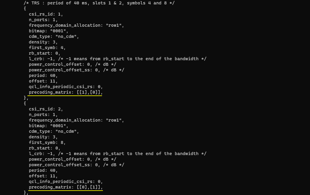
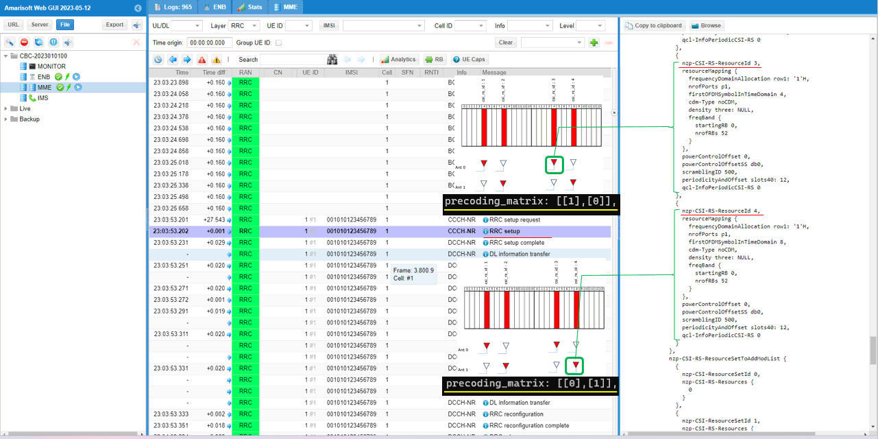
For csi_rs_id: 3, the precoding_matrix is set to [[1], [0]]. Here, the index of the element [1] is 0 (i.e, the first elements (index 0) is set to 1). So the physicall antenna mapped to this csi rs is antenna 0.
For csi_rs_id: 4, the precoding_matrix is set to [[0], [1]]. Here, the index of the element [1] is 1 (i.e, the first elements (index 1) is set to 1). So the physicall antenna mapped to this csi rs is antenna 1.
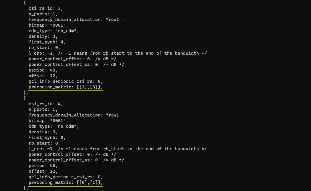
Since the mapping between the logical port of csi-rs and physical antenna of gNB is up to the implementation of the equipment vendor, the mapping information is not shown in the protocol log. I am showing the log here just to explain how the configuration is related to the rrc configuration of TRS csi-rs.
Here you see the first pair of TRS csi-Resource. The physical antenna mapping configured by the precoding_matrix cannot be reflected in RRC message since it is lower layer internal mapping in Amarisoft gNB.
Here you see the second pair of TRS csi-Resource. The physical antenna mapping configured by the precoding_matrix cannot be reflected in RRC message since it is lower layer internal mapping in Amarisoft gNB.
RRC / NAS Signaling
RrcSetup (SA)
: This is the RrcSetup message sent by gNB to configure NR SA. (
{
message c1: rrcSetup: {
rrc-TransactionIdentifier 0,
criticalExtensions rrcSetup: {
radioBearerConfig {
...
},
masterCellGroup {
cellGroupId 0,
rlc-BearerToAddModList {
...
},
mac-CellGroupConfig {
...
},
physicalCellGroupConfig {
pdsch-HARQ-ACK-Codebook dynamic
},
spCellConfig {
spCellConfigDedicated {
initialDownlinkBWP {
pdcch-Config setup: {
...
},
pdsch-Config setup: {
dmrs-DownlinkForPDSCH-MappingTypeA setup: {
dmrs-AdditionalPosition pos1
},
tci-StatesToAddModList {
{
tci-StateId 0,
qcl-Type1 {
referenceSignal ssb: 0,
qcl-Type typeD
}
},
{
tci-StateId 1,
qcl-Type1 {
referenceSignal csi-rs: 0,
qcl-Type typeD
}
},
{
tci-StateId 2,
qcl-Type1 {
referenceSignal ssb: 0,
qcl-Type typeC
},
qcl-Type2 {
referenceSignal csi-rs: 0,
qcl-Type typeD
}
}
},
...
zp-CSI-RS-ResourceToAddModList {
{
zp-CSI-RS-ResourceId 0,
resourceMapping {
frequencyDomainAllocation row4: '100'B,
nrofPorts p4,
firstOFDMSymbolInTimeDomain 8,
cdm-Type fd-CDM2,
density one: NULL,
freqBand {
startingRB 0,
nrofRBs 52
}
},
periodicityAndOffset slots80: 1
}
},
p-ZP-CSI-RS-ResourceSet setup: {
zp-CSI-RS-ResourceSetId 0,
zp-CSI-RS-ResourceIdList {
0
}
}
}
},
firstActiveDownlinkBWP-Id 0,
uplinkConfig {
initialUplinkBWP {
pucch-Config setup: {
...
},
pusch-Config setup: {
...
},
srs-Config setup: {
...
}
},
firstActiveUplinkBWP-Id 0,
pusch-ServingCellConfig setup: {
}
},
pdcch-ServingCellConfig setup: {
},
pdsch-ServingCellConfig setup: {
...
},
csi-MeasConfig setup: {
nzp-CSI-RS-ResourceToAddModList {
{
nzp-CSI-RS-ResourceId 0,
resourceMapping {
frequencyDomainAllocation other: '100000'B,
nrofPorts p2,
firstOFDMSymbolInTimeDomain 4,
cdm-Type fd-CDM2,
density one: NULL,
freqBand {
startingRB 0,
nrofRBs 52
}
},
powerControlOffset 0,
powerControlOffsetSS db0,
scramblingID 500,
periodicityAndOffset slots80: 1,
qcl-InfoPeriodicCSI-RS 0
},
{
nzp-CSI-RS-ResourceId 1,
resourceMapping {
frequencyDomainAllocation row1: '1'H,
nrofPorts p1,
firstOFDMSymbolInTimeDomain 4,
cdm-Type noCDM,
density three: NULL,
freqBand {
startingRB 0,
nrofRBs 52
}
},
powerControlOffset 0,
powerControlOffsetSS db0,
scramblingID 500,
periodicityAndOffset slots40: 11,
qcl-InfoPeriodicCSI-RS 0
},
{
nzp-CSI-RS-ResourceId 2,
resourceMapping {
frequencyDomainAllocation row1: '1'H,
nrofPorts p1,
firstOFDMSymbolInTimeDomain 8,
cdm-Type noCDM,
density three: NULL,
freqBand {
startingRB 0,
nrofRBs 52
}
},
powerControlOffset 0,
powerControlOffsetSS db0,
scramblingID 500,
periodicityAndOffset slots40: 11,
qcl-InfoPeriodicCSI-RS 0
},
{
nzp-CSI-RS-ResourceId 3,
resourceMapping {
frequencyDomainAllocation row1: '1'H,
nrofPorts p1,
firstOFDMSymbolInTimeDomain 4,
cdm-Type noCDM,
density three: NULL,
freqBand {
startingRB 0,
nrofRBs 52
}
},
powerControlOffset 0,
powerControlOffsetSS db0,
scramblingID 500,
periodicityAndOffset slots40: 12,
qcl-InfoPeriodicCSI-RS 0
},
{
nzp-CSI-RS-ResourceId 4,
resourceMapping {
frequencyDomainAllocation row1: '1'H,
nrofPorts p1,
firstOFDMSymbolInTimeDomain 8,
cdm-Type noCDM,
density three: NULL,
freqBand {
startingRB 0,
nrofRBs 52
}
},
powerControlOffset 0,
powerControlOffsetSS db0,
scramblingID 500,
periodicityAndOffset slots40: 12,
qcl-InfoPeriodicCSI-RS 0
}
},
nzp-CSI-RS-ResourceSetToAddModList {
{
nzp-CSI-ResourceSetId 0,
nzp-CSI-RS-Resources {
0
}
},
{
nzp-CSI-ResourceSetId 1,
nzp-CSI-RS-Resources {
1,
2,
3,
4
},
trs-Info true
}
},
csi-IM-ResourceToAddModList {
{
csi-IM-ResourceId 0,
csi-IM-ResourceElementPattern pattern1: {
subcarrierLocation-p1 s8,
symbolLocation-p1 8
},
freqBand {
startingRB 0,
nrofRBs 52
},
periodicityAndOffset slots80: 1
}
},
csi-IM-ResourceSetToAddModList {
{
csi-IM-ResourceSetId 0,
csi-IM-Resources {
0
}
}
},
csi-ResourceConfigToAddModList {
{
csi-ResourceConfigId 0,
csi-RS-ResourceSetList nzp-CSI-RS-SSB: {
nzp-CSI-RS-ResourceSetList {
0
}
},
bwp-Id 0,
resourceType periodic
},
{
csi-ResourceConfigId 1,
csi-RS-ResourceSetList csi-IM-ResourceSetList: {
0
},
bwp-Id 0,
resourceType periodic
},
{
csi-ResourceConfigId 2,
csi-RS-ResourceSetList nzp-CSI-RS-SSB: {
nzp-CSI-RS-ResourceSetList {
1
}
},
bwp-Id 0,
resourceType periodic
}
},
csi-ReportConfigToAddModList {
{
reportConfigId 0,
resourcesForChannelMeasurement 0,
csi-IM-ResourcesForInterference 1,
reportConfigType periodic: {
reportSlotConfig slots80: 9,
pucch-CSI-ResourceList {
{
uplinkBandwidthPartId 0,
pucch-Resource 13
}
}
},
reportQuantity cri-RI-PMI-CQI: NULL,
reportFreqConfiguration {
cqi-FormatIndicator widebandCQI,
pmi-FormatIndicator widebandPMI
},
timeRestrictionForChannelMeasurements notConfigured,
timeRestrictionForInterferenceMeasurements notConfigured,
codebookConfig {
codebookType type1: {
subType typeI-SinglePanel: {
nrOfAntennaPorts two: {
twoTX-CodebookSubsetRestriction '111111'B
},
typeI-SinglePanel-ri-Restriction '03'H
},
codebookMode 1
}
},
groupBasedBeamReporting disabled: {
},
cqi-Table table2,
subbandSize value1
}
}
},
tag-Id 0
}
Tips
Resource Collision Problem
: One of the most common issues that you would encounter when you are configuring CSI RS manually (not using resource_auto) would be the error caused by collision among resources various other channels. Unfortunately there is no single shot solution to fix this automatically. It there is such a way, we might have implmented in our software. We do support a certain level of automation as described in this section and it will suit your purpose for most of the test, but the auto_configuration cannot be as flexible as manual configuration. Here I just want to provide some general guidelines for the case where you want to configure CSI RS manually and come across with physical resource collision issue,
Step 1 : Draw a time domain resource allocation map and remove the collision
First step is to draw all the physical channels and signals on time domain symbol map as follows. You should draw not only for CSI-RS that you want to configure but also draw all other resources (like SSB, PDSCH DMRS etc) and make it sure that there is no collision among any of those physical channels and signals.
You may try to tweak following configuration parameters to avoid time-domain collision :
- ssb_pos_bitmap
- dmrs_type_a_pos
- dmrs_add_pos: 1,
- dmrs_type: 1,
- dmrs_max_len: 1
- *_csi_rs_resource ->first_symb
First draw a picture showing all the major physical signal resources except CSI-RS and mark which slots/symbols are allowed for CSI-RS and which are not allowed as shown below. (

Then allocate the various CSI-RS to any of the allowed slots/symbols. There can be many possibilities, but following diagram shows only one of those possibilities and this will configured into the configuration file for this test. (

Step 2 : Change transmission slot
There might be some cases where you cannot avoid all the collision for some reasons such as :
- available resources for each slot is not enough to accommodate all the configuration
- test requirement does not allow the changes of csi-rs symbol location
In this case, you may distribute the configurations among multiple non-overlapping slot. You may tweak following configuration to distribute the csi-rs resources to different slots.
- *_csi_rs_resource -> period
- *_csi_rs_resource -> offset
Step 3 : Change Frequency Domain Resources
If step 1 and step 2 does not solve the problem, you may try tweaking frequency domain resource allocation of CSI-RS resources using following configuration.
- *_csi_rs_resource ->bitmap
Setting n1, n2
When you want to set n1, n2 of codebook_config[], you should associate it with nzp_csi_rs_resource->n_ports parameters, NOT with number of physical antenna(n_antenna_dl).
No codebook configuration in RRC message ?
If you don't see codebook setting in RRC message (RRCSetup or RrcReconfiguration) in the log where you expect to see, check the number of port that is configured for the csi configuration. If the number of ports is only 1, the codebook setting will not be configured in the RRC message.
If the RRC message is for the serving cell, check the number of port setting in the serving cell. If the RRC message is for another cell (e.g, RrcReconfiguration for Handover) check out the number of port setting for the target (destination) cell.
Logging Decoded CSI Report
In default phy log, you would see only the csi bitmap on PUCCH or PUSCH which would be hard to understand the meaning of each bits. If you want to get those bitmap decoded and printed into the log file. You have two options.
Option 1 : Add phy.csi=1 to log option
Add phy.csi=1 to log option in the confgiuration as shown below.
|
log_options: "all.level=debug,all.max_size=1, phy.csi=1", |
Option 2 : Enable CSI in WebGUI Property Window
You can enable CSI in ENB property window in WebGUI (
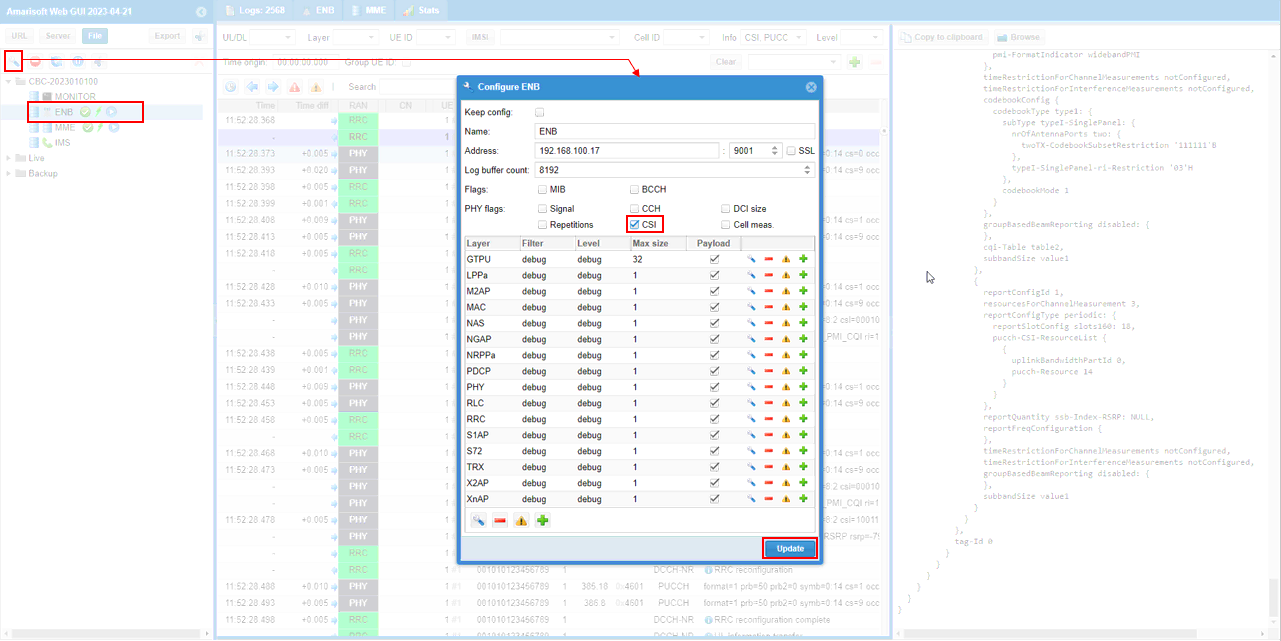
Then you can get the decoded CSI report as shown below.
