NR SA TimeDomainAllocationList
This tutorial is about configuration for PDSCH/PUSCH-TimeDomainAlloationList in RRC message. With default configuration, this IE is automatically configured by the callbox based on the TDD pattern specified in the configuration file. Even though it is possible to configure k1, k2 manually, it is not strongly recommended since it is challenging to configure it without colliding with internal auto-configuration algorithm. However, I will show you how to configure it manually anyway in Test2 for your reference
This tutorial is based on 2021-11-19 release. The autoconfiguration algorithm may evolve (change) in a future release. The tutorial will be updated if the algorithm changes
In this tutorial, it is assumed that you are faimiliar with basic operations of Amari Callbox operation. So in this tutorial, I will explain only about the configuration and analyzing the test result in the WebGUI log.
TimeDomainAllocationList are the list of parameters that configures k0, k1, k2. The simplified definition of k0, k1, k2 are as follows :
- k0 : The gap (in number of slots) between DCI and corresponding PDSCH transmission. k0 = 0 or omit indicates that PDSCH is transmitted in the same slot as DCI. (details)
- k1 : The gap (in number of slots) between PDSCH and the corresponding PUCCH (Ack/Nack) (details)
- k2 : The gap (in number of slots) between DCI(UL Grant) and corresponding PUSCH transmission (details)
- SLIV : Start and Length Indicator Value representing the starting symbol and number of symbols for PDSCH and PUSCH (details)
Table of Contents
- NR SA TimeDomainAllocationList
- Introduction
- Summary of the Tutorial
- Test Setup
- Key Configuration Parameters
- Configuration
- Perform the Test
- Test 1 : Using default configuration
- Test 2 : Manual configuration of k1,k2,msg3_k2
- Test 3 : Changing PDSCH mapping type(TypeB, n_symb)
- Test 4 : Changing PDSCH mapping type(TypeB) and SLIV
- Test 5 : Changing PUSCH mapping type(TypeB) and SLIV
- RRC / NAS Signaling
Introduction
The configuration of PDSCH/PUSCH-TimeDomainAllocationList in the context of 5G NR (New Radio) RRC (Radio Resource Control) signaling is a fundamental aspect of physical layer scheduling and resource allocation within cellular networks. This configuration governs the timing relationships and resource mapping for both downlink (PDSCH: Physical Downlink Shared Channel) and uplink (PUSCH: Physical Uplink Shared Channel) transmissions. At its core, the TimeDomainAllocationList defines critical parameters such as k0, k1, and k2, which determine the scheduling offsets and timing gaps between control information (DCI) and data transmissions, as well as the timing of associated uplink feedback (PUCCH: Physical Uplink Control Channel). In practical 5G test environments, such as with the Amari Callbox system, these allocations are typically auto-configured by the system based on the underlying TDD (Time Division Duplex) pattern, ensuring optimal operation and avoiding parameter conflicts. However, manual configuration may be required in certain testing or development scenarios, which introduces complexity due to the intricate interplay with internal scheduling algorithms. Mastery of these configurations is essential for advanced network validation, troubleshooting, and performance optimization, reflecting the close relationship between RRC configuration, physical layer resource allocation, and end-to-end radio system behavior. This tutorial delves into the manual configuration process, discusses the implications of parameter selection, and provides guidance for interpreting results within the WebGUI of the Amari Callbox, with a specific focus on the release as of November 2021 and awareness of possible algorithmic evolution in future releases.
-
Context and Background
- The tutorial focuses on the technical configuration of TimeDomainAllocationList parameters (k0, k1, k2) within the RRC layer, critical for controlling the timing and structure of downlink and uplink transmissions in 5G NR.
- These parameters directly influence how data and control information are mapped onto physical resources, affecting system latency, throughput, and reliability.
- The tutorial uses the Amari Callbox platform, a widely used 5G test system, highlighting real-world application and practical analysis via its WebGUI interface.
-
Relevance and Importance
- Understanding and configuring TimeDomainAllocationList is essential for advanced 5G system testing, performance tuning, and protocol validation.
- Manual configuration, although not generally recommended due to potential conflicts with automatic algorithms, provides deeper insight into 5G NR scheduling mechanisms and enables specialized test scenarios.
- The knowledge gained is valuable for engineers working on network equipment testing, UE development, and radio protocol analysis.
-
Learning Outcomes
- Learners will gain a comprehensive understanding of k0, k1, and k2 timing parameters and their impact on 5G NR scheduling.
- The tutorial will guide users through the process of manually configuring the TimeDomainAllocationList in the Amari Callbox WebGUI environment.
- Learners will develop the ability to analyze test results and interpret system behavior resulting from different configuration settings.
- Insights into the evolution and adaptability of autoconfiguration algorithms across software releases will be provided.
-
Prerequisite Knowledge
- Familiarity with basic Amari Callbox operations is assumed; the tutorial will focus exclusively on advanced configuration and analysis topics.
- Understanding of 5G NR architecture, RRC signaling, and the physical channel structure (PDSCH, PUSCH, PUCCH) is recommended for maximum comprehension.
- Prior experience with test systems and interpreting log outputs within a WebGUI environment will be beneficial.
Summary of the Tutorial
This tutorial provides a comprehensive overview of low layer NR TDD slot allocation testing using a gNB simulator (Callbox) and UE setup. The procedures focus on verifying TDD slot allocations, k1/k2 values, mapping types, and SLIV configurations through both default and manual settings. Below is a structured summary of the test methodologies and procedures described in the tutorial.
-
Test Setup:
- Utilizes a basic setup with a Callbox and UE for low layer testing.
- The provided SIM card is used as-is, with configuration changes possible via a referenced Configuration Guide.
-
Key Configuration Parameters:
- Critical parameters include k1, k2, mapping_type, start_symb, n_symb, msg3_k2, and tdd_ul_dl_config.
- TDD pattern parameters such as ref_subcarrier_spacing, pattern1 and pattern2 (each with period, dl_slots, ul_slots, dl_symbols, ul_symbols) are important for test configuration.
-
General Test Execution Steps:
- Configure the gNB using gnb-sa-tdla.cfg (derived from default gnb-sa.cfg).
- Default MME (mme-ims.cfg) and IMS (ims.default.cfg) configurations are used.
- Perform NR SA attach; verify correct SRS and slot allocations via log analysis.
-
Test 1: Using Default Configuration
- Apply the default gnb-sa.cfg settings without modifications.
- Select TDD pattern using NR_TDD_CONFIG; set duplex mode (NR_TDD) to 1 (TDD), and NR_TDD_CONFIG to 2 (a sample Amarisoft configuration).
- k1 is not set manually; gNB determines it automatically.
- Verify in logs:
- TimeDomainAllocationList is automatically configured (usually two elements: full slot and partial slot).
- Downlink/Uplink slot and symbol counts are determined by tdd-UL-DL-ConfigurationCommon (e.g., 5ms period, 7 DL slots, 2 UL slots, etc.).
- k1 values are automatically set based on TDD pattern; manual override is not recommended.
- Error messages on the eNB screen assist troubleshooting if configuration issues arise.
-
Test 2: Manual Configuration of k1, k2, msg3_k2
- Demonstrates manual setting of k1, k2, and msg3_k2 in gnb-sa-tdla.cfg.
- Uses the same TDD pattern as Test 1 (NR_TDD_CONFIG set to 2).
- Manual configuration is for demonstration; users are cautioned against manual changes unless fully understood.
- After manual k1 configuration, k2 and msg3_k2 must be set accordingly.
- Log analysis:
- TimeDomainAllocationList and SLIV elements are still auto-determined by gNB; manual changes are discouraged.
- For pusch-TimeDomainAllocationList, three elements are configured: two for regular PUSCH, one for msg3 PUSCH.
- The k2 value in RRC is calculated using msg3_k2 and a 3GPP-defined delta (rrc_k2 = msg3_k2 - Delta).
- Configuration is verified for errors using the eNB screen.
-
Test 3: Changing PDSCH Mapping Type (TypeB, n_symb)
- Demonstrates configuration of PDSCH mapping type B for mini-slot operation (2, 4, or 7 symbols).
- Manual setting of mapping_type, start_symb, and n_symb in the PDSCH configuration.
- SLIV (Start Symbol and Length Indicator Value) is manually configured via these parameters.
- Logs are checked to confirm TimeDomainAllocationList and mappingType reflect the configured values.
- Errors are validated on the eNB screen.
-
Test 4: Changing PDSCH Mapping Type (TypeB) and SLIV
- Extends Test 3 by configuring both mapping type B and SLIV via mapping_type, start_symb, and n_symb.
- Confirms via logs that TimeDomainAllocationList and mappingType are set as specified in the configuration.
- Ensures no configuration errors are present on the eNB screen.
-
Test 5: Changing PUSCH Mapping Type (TypeB) and SLIV
- Demonstrates manual configuration of PUSCH mapping type B and SLIV using mapping_type, start_symb, and n_symb in PUSCH parameters.
- Checks that the TDAL (Time Domain Allocation List) elements are automatically determined by the gNB, but mappingType and SLIV are applied as configured.
- Ensures error-free configuration by checking the eNB screen.
General Methodology:
- Each test consists of modifying configuration files as required, applying the configuration, performing NR SA attach, and verifying the resulting configuration via log analysis (TimeDomainAllocationList, mappingType, k1/k2 values, etc.).
- Emphasis is placed on understanding the consequences of manual versus automatic configuration, especially for timing-related parameters (k1, k2, msg3_k2, SLIV, mappingType).
- Always confirm the absence of configuration errors via the eNB screen and use provided log outputs for validation.
Test Setup
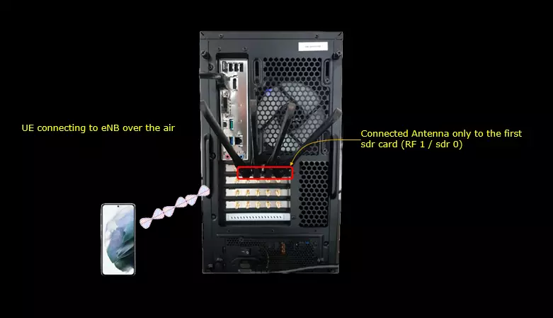
Test setup for this tutorial is as shown below. This is just for low layer testing, you may not need any complicated IP layer setup.
- SIM Card used in this tutorial is the one delivered with the system as it is.
- If you want to change the configuration, The tutorial Configuration Guide would help
Key Configuration Parameters
Followings are important configuration parameters for this tutorial. You may click on the items for the descriptions from Amarisoft documents.
- k1
- k2
- mapping_type
- start_symb
- n_symb
- msg3_k2
- tdd_ul_dl_config : In this link, you can get the descriptions for all the parameters listed below
- ref_subcarrier_spacing
- pattern1
- period
- dl_slots
- ul_slots
- dl_symbols
- ul_symbols
- pattern2
- period
- dl_slots
- ul_slots
- dl_symbols
- ul_symbols
Configuration
I have used gnb-sa-tdla.cfg which is copied and modified from gnb-sa.cfg. The details of specific parameters to be tested will be shown under each test.
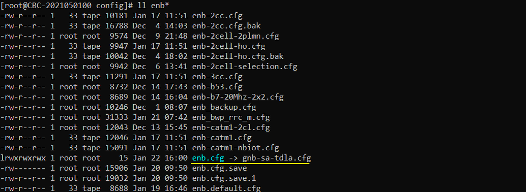
I am using the default mme (mme-ims.cfg), ims (ims.default.cfg) config as shown below.

Perform the Test
Testing process is simple. You only have to do NR SA attach (See NR SA Attach tutorial if you are not familiar with the process). The important part is to check the log and verify if you get the SRS as configured.
Test 1 : Using default configuration
Set the configuration in gnb-sa-tdla.cfg as follows. This test uses the contents of gnb-sa.cfg as it is (without changing any contents in it).
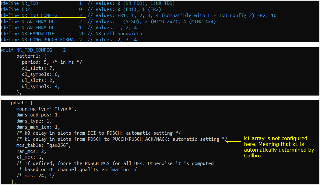
In the configuration file, you can select any specific tdd pattern with the parameter NR_TDD_CONFIG. To apply TDD configuration, you first need to configure the duplex mode (NR_TDD) to 1 (TDD). And then I set NR_TDD_CONFIG to 2 which is one of default sample configuration provided by Amarisoft sample configuration.
k1 in pdsch configuration is not set in this test meaning that k1 is automatically determined by gNB software.
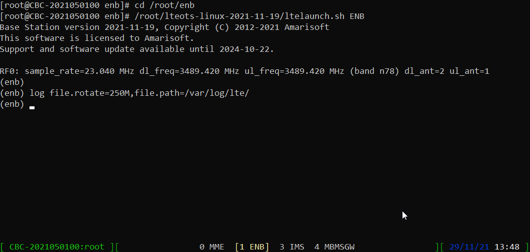
Make it sure that you don't see any errors in enb screen. If your configuration has any problem, you may get pretty useful error message which may be helpful for troubleshooting.
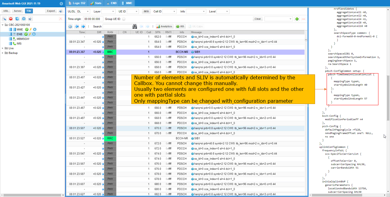
You can confirm how TimeDomainAllocationList is configured in RRC from the log as shown below. Number of elements and SLIV is automatically determined and set by the gNB(Callbox). It is not advisable to change it manually. Usually two elements are configured, one with full slots and the other one with partial slot. MappingType can be changed by configuration file if want.
c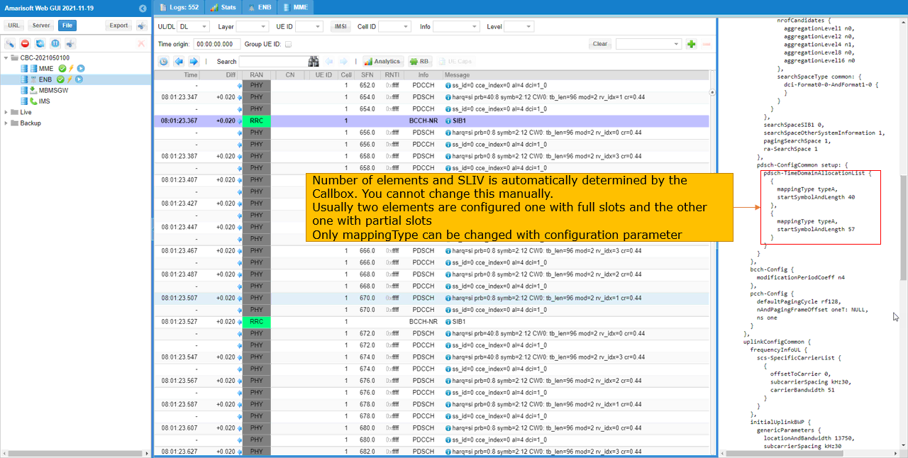
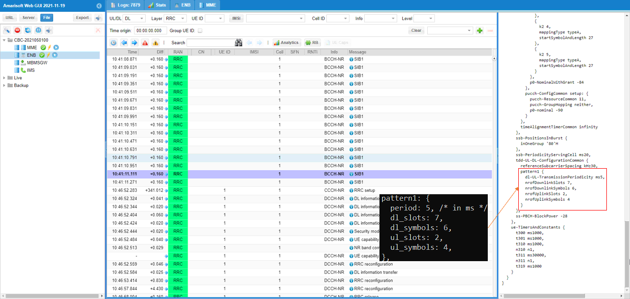
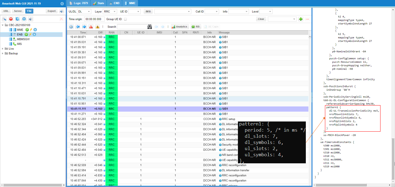
Since automatic configuration of k1 and k2 is affected by tdd-UL-DL-ConfigurationCommon, it would be good to check on this configuration as well. In this test, dl-UL-TransmissionPeriodicity is set to 5ms which correponds to 10 slots in case of subcarrier spacing 30Khz. The number of downlink slot(nrofDownlinkSlots) are set to 7, Number of Downlink Symbols(nrofDownlinkSymbols) are set to 6 and the number of uplink slot(nrofUplinkSlots) are set to 2, Number of Uplink Symbols(nrofUplinkSymbols) are set to 4
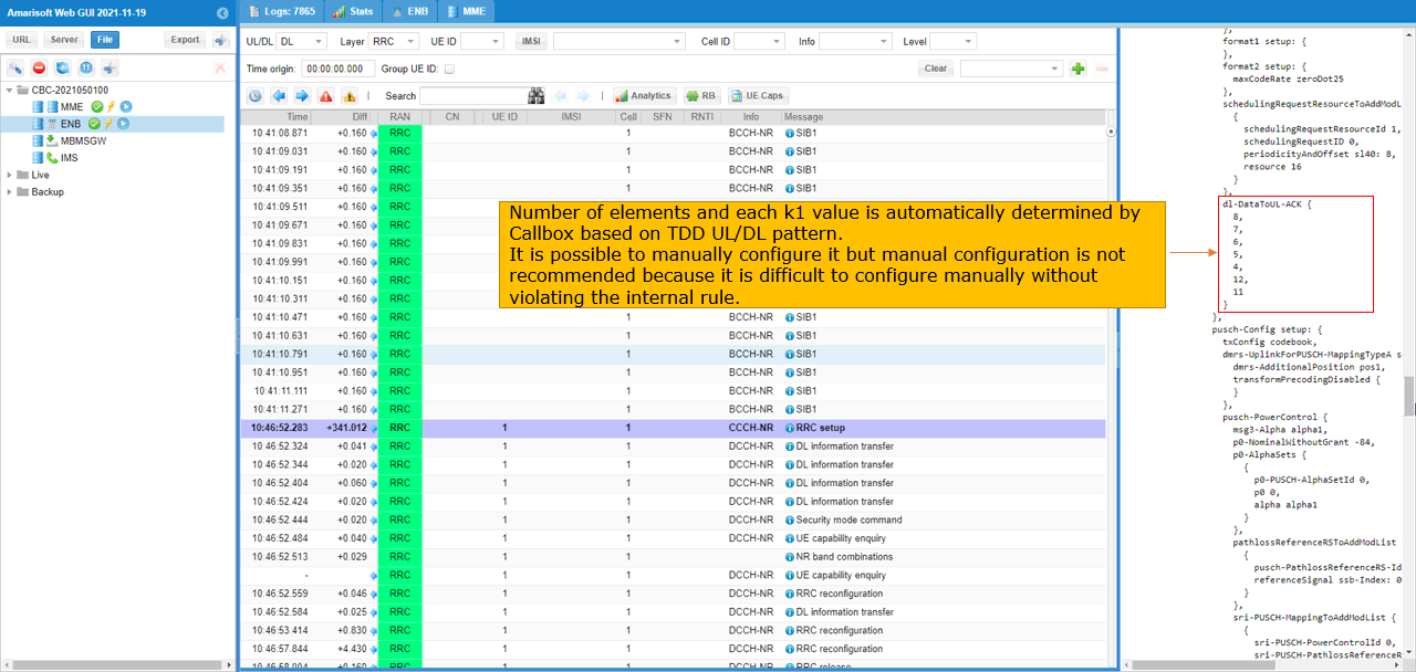
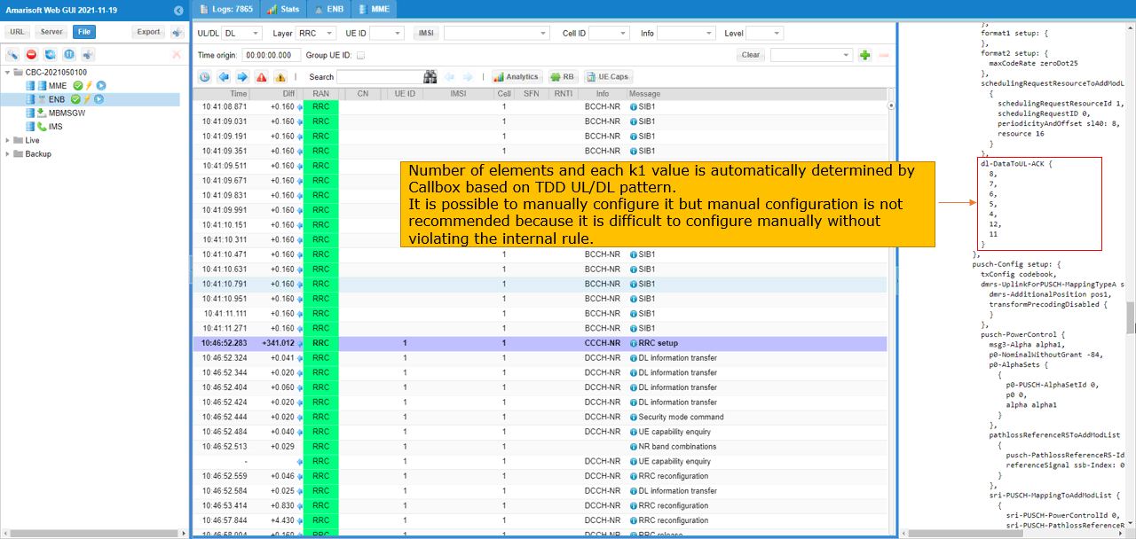
Now let's confirm on k1 configuration in RRC. you can check it with dl-DataToUL-ACK IE. The number of elements and each k1 values is automatically determined by Callbox(gNB) based on TDD UL/DL pattern. It is possible to manually configure it but manual configuration is not recommended because it is difficult to configure manually without violating the internal rules.
Test 2 : Manual configuration of k1,k2,msg3_k2
In this test, I will show you how configure k1,k2,msg3_k2 value manually. This is just for demonstation/tutorial purpose, it is not recommended to change these variables manually since it is tricky to set the proper values without violating the callbox's internal rule
Set the configuration in gnb-sa-tdla.cfg as follows.
In the configuration file, you can select any specific tdd pattern with the parameter NR_TDD_CONFIG. To apply TDD configuration, you first need to configure the duplex mode (NR_TDD) to 1 (TDD). And then I set NR_TDD_CONFIG to 2 which is one of default sample configuration provided by Amarisoft sample configuration.
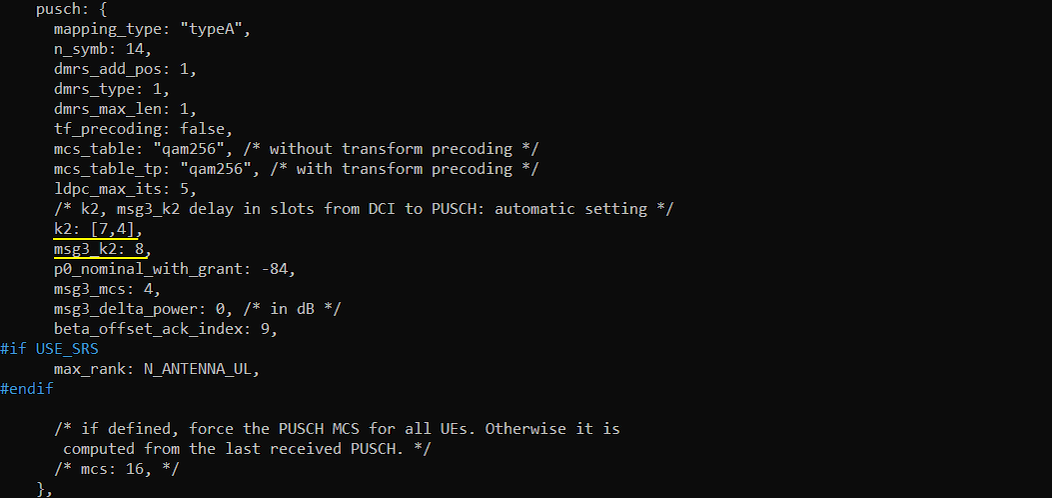
k1 in pdsch configuration is set manually, but this is just for information purpose. I do not enourage users to do this unless it is really required and user completes understand what to do. If you configure the k1 manually, you should configure k2, msg3_k2 accordingly as well.
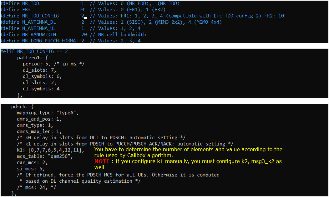
Since you configured k1 manually, you should set k2 and msg3_k2 according to the k1 settings.
In this test, one of the default configuration (NR_TDD_CONFIG 2) is used. With this tdd pattern, the period is 5 ms which is 10 slots for the case of Subcarrier Spacing 30Khz, number of downlink slot is 7 and the number of downlink symbol is 6 and number of uplink slot is 2 and the number of uplink symbol is 4.

The configuration shown above can be illustrated as follows. It would be a good practice to convert the configuration into illustration.

Make it sure that you don't see any errors in enb screen. If your configuration has any problem, you may get pretty useful error message which may be helpful for troubleshooting.

You can confirm the configuration in SIB1 as below. You can confirm how TimeDomainAllocationList is configured in RRC from the log as shown below. Number of elements and SLIV is automatically determined and set by the gNB(Callbox). It is not advisable to change it manually. Usually two elements are configured, one with full slots and the other one with partial slot. MappingType can be changed by configuration file if want.
In this test, one of the default configuration (NR_TDD_CONFIG 2) is used. With this tdd pattern, the period is 5 ms which is 10 slots for the case of Subcarrier Spacing 30Khz, number of downlink slot is 7 and the number of downlink symbol is 6 and number of uplink slot is 2 and the number of uplink symbol is 4.
Now let's confirm on k1 configuration in RRC. you can check it with dl-DataToUL-ACK IE. The number of elements and each k1 values is automatically determined by Callbox(gNB) based on TDD UL/DL pattern. It is possible to manually configure it but manual configuration is not recommended because it is difficult to configure manually without violating the internal rules.
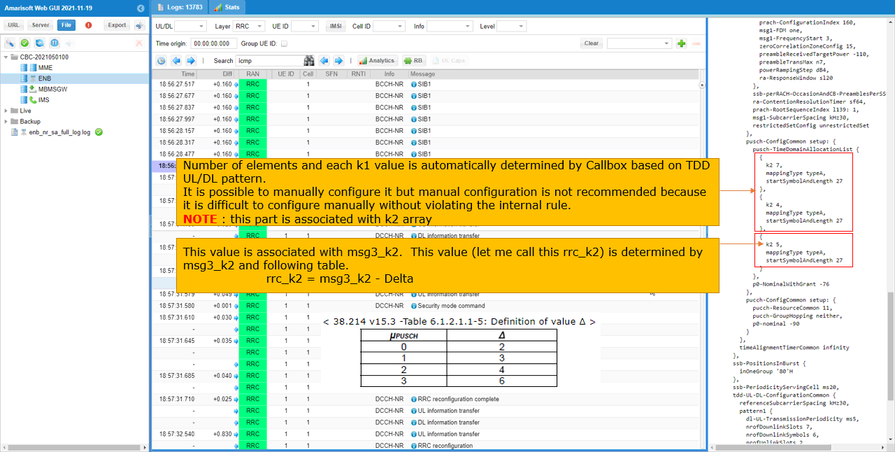
Then check on pusch-TimeDomainAllocationList. In this specific test case, three elements are configured. The first two are for the regular PUSCH and the last one is for msg3 PUSCH. You may notice that k2 value set in this RRC message is a little bit different from msg3_k2 you set in the configuration file. The reason is that the msg3 k2 set in the RRC message is not the same as msg3_k2 you set in the configuration file. The k2 value in the RRC is determined by msg3_k2 value and Delta value predefined in 3GPP in the formula rrc_k2 = msg3_k2 - Delta.
Test 3 : Changing PDSCH mapping type(TypeB, n_symb)
In this test, I will show you how to configure PDSCH mapping typeB. With the mapping type B, you can configure mini-slot (with the number of symbos 2,4,7).
Set the configuration in gnb-sa-tdla.cfg as follows.
In the configuration file, you can select any specific tdd pattern with the parameter NR_TDD_CONFIG. To apply TDD configuration, you first need to configure the duplex mode (NR_TDD) to 1 (TDD). And then I set NR_TDD_CONFIG to 2 which is one of default sample configuration provided by Amarisoft sample configuration.
In this case, the SLIV value (derived from mapping type and the number of symbols) is configured manually in pdsch configuration parameter. You can change SLIV value by setting mapping_type,start_symb and n_symb in pdsch.
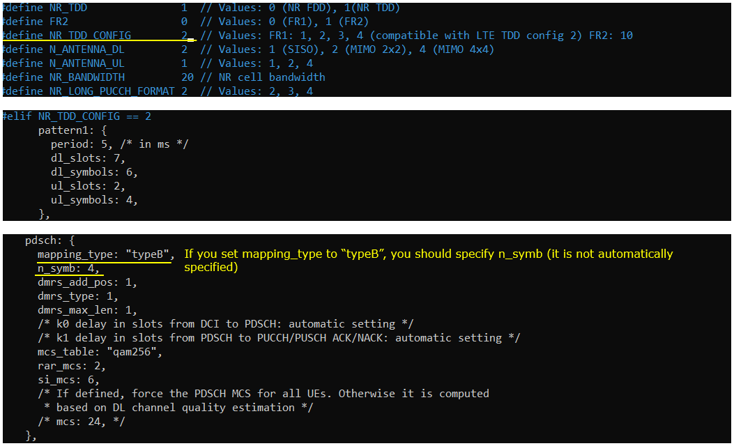
Make it sure that you don't see any errors in enb screen. If your configuration has any problem, you may get pretty useful error message which may be helpful for troubleshooting.

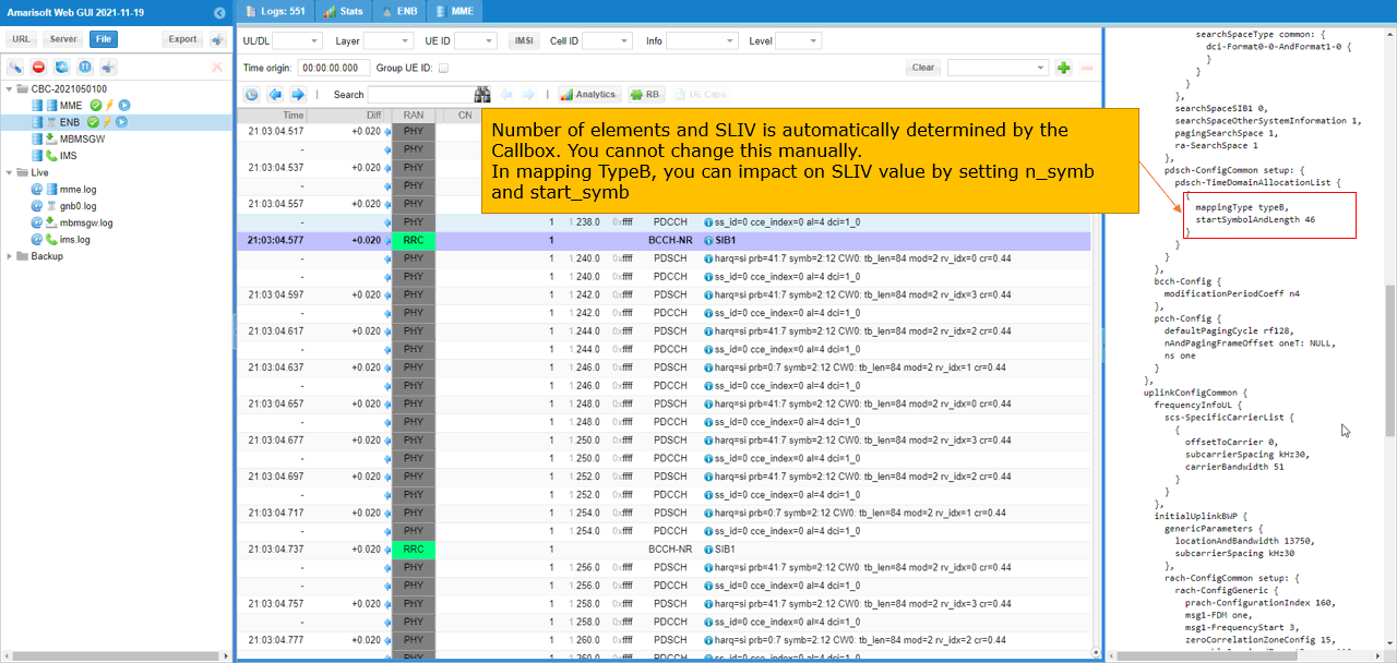
You can confirm the configuration in SIB1 as below. You can confirm how TimeDomainAllocationList is configured in RRC from the log as shown below. In this case, the number of SLIV(startSymbolAndLength), mappingType is configured as you set in the configuration file.
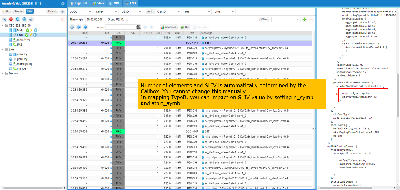
Test 4 : Changing PDSCH mapping type(TypeB) and SLIV
In this test, I will show you how to configure PDSCH mapping typeB. With the mapping type B and SLIV by setting the start symbol and length of the symbols.
Set the configuration in gnb-sa-tdla.cfg as follows.
In the configuration file, you can select any specific tdd pattern with the parameter NR_TDD_CONFIG. To apply TDD configuration, you first need to configure the duplex mode (NR_TDD) to 1 (TDD). And then I set NR_TDD_CONFIG to 2 which is one of default sample configuration provided by Amarisoft sample configuration.
In this case, the SLIV value (derived from mapping type and the number of symbols) is configured manually in pdsch configuration parameter. You can change SLIV value by setting mapping_type,start_symb and n_symb in pdsch.
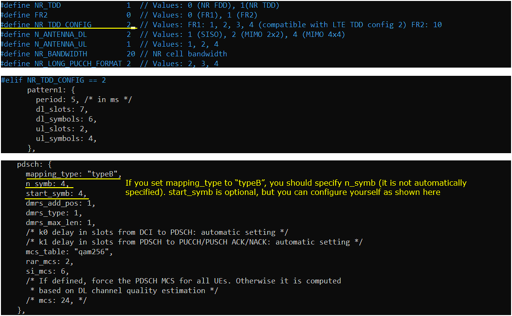
Make it sure that you don't see any errors in enb screen. If your configuration has any problem, you may get pretty useful error message which may be helpful for troubleshooting.

You can confirm the configuration in SIB1 as below. You can confirm how TimeDomainAllocationList is configured in RRC from the log as shown below. In this case, the number of SLIV(startSymbolAndLength), mappingType is configured as you set in the configuration file.
Test 5 : Changing PUSCH mapping type(TypeB) and SLIV
In this test, I will show you how to configure PUSCH mapping typeB. With the mapping type B and SLIV by setting the start symbol and length of the symbols.
Set the configuration in gnb-sa-tdla.cfg as follows.
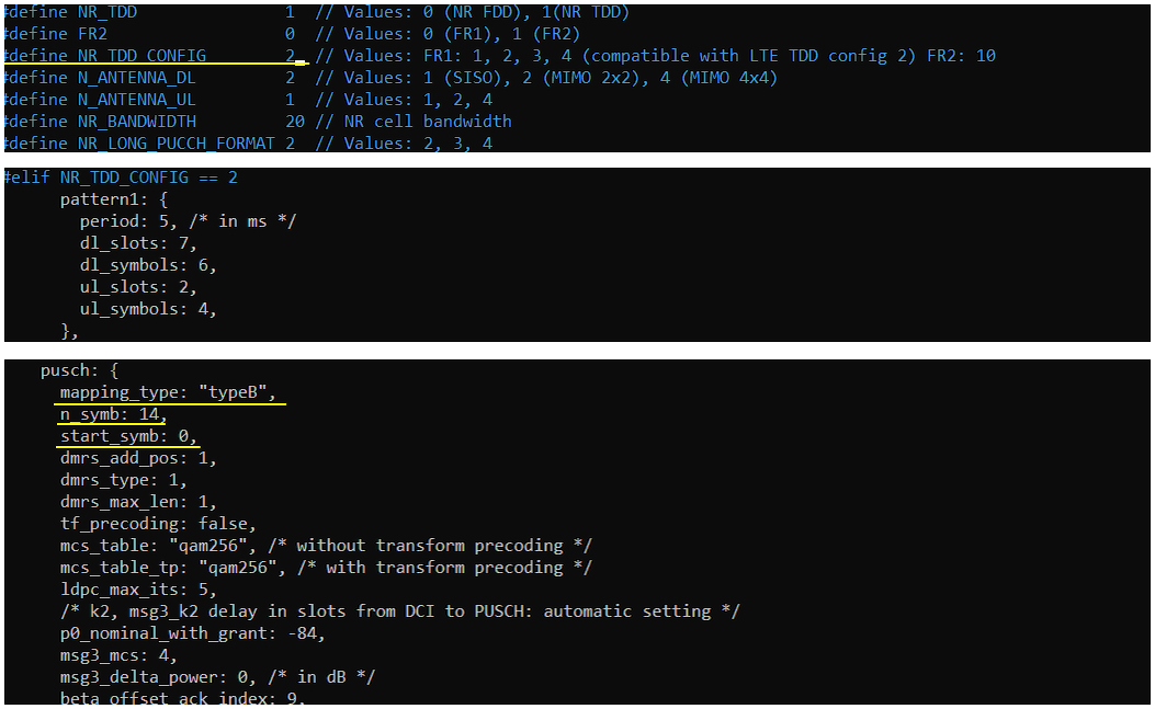
In the configuration file, you can select any specific tdd pattern with the parameter NR_TDD_CONFIG. To apply TDD configuration, you first need to configure the duplex mode (NR_TDD) to 1 (TDD). And then I set NR_TDD_CONFIG to 2 which is one of default sample configuration provided by Amarisoft sample configuration.
In this case, the SLIV value (derived from mapping type and the number of symbols) is configured manually in pusch configuration parameter. You can change SLIV value by setting mapping_type,start_symb and n_symb in pusch.
Make it sure that you don't see any errors in enb screen. If your configuration has any problem, you may get pretty useful error message which may be helpful for troubleshooting.

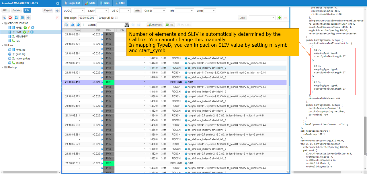
You can confirm the configuration in SIB1 as below. You can confirm how TimeDomainAllocationList is configured in RRC from the log as shown below. In this case, the number of TDAL elements are configured automatically by gNB, mappingType and SLIV(startSymbolAndLength) value is configured as you set in the configuration file.
RRC / NAS Signaling
SIB1 (SA)
: This is the SIB1 message sent by gNB to configure NR SA. (
{
message c1: systemInformationBlockType1: {
cellSelectionInfo {
...
},
cellAccessRelatedInfo {
...
connEstFailureControl {
...
},
servingCellConfigCommon {
downlinkConfigCommon {
frequencyInfoDL {
...
},
initialDownlinkBWP {
genericParameters {
locationAndBandwidth 13750,
subcarrierSpacing kHz30
},
pdcch-ConfigCommon setup: {
...
},
pdsch-ConfigCommon setup: {
pdsch-TimeDomainAllocationList {
{
mappingType typeA,
startSymbolAndLength 40
},
{
mappingType typeA,
startSymbolAndLength 57
}
}
}
},
bcch-Config {
...
},
pcch-Config {
...
}
},
uplinkConfigCommon {
frequencyInfoUL {
...
},
initialUplinkBWP {
genericParameters {
...
},
rach-ConfigCommon setup: {
...
},
pusch-ConfigCommon setup: {
pusch-TimeDomainAllocationList {
{
k2 7,
mappingType typeA,
startSymbolAndLength 27
},
{
k2 4,
mappingType typeA,
startSymbolAndLength 27
},
{
k2 5,
mappingType typeA,
startSymbolAndLength 27
}
},
p0-NominalWithGrant -76
},
pucch-ConfigCommon setup: {
...
}
},
timeAlignmentTimerCommon infinity
},
ssb-PositionsInBurst {
inOneGroup '80'H
},
ssb-PeriodicityServingCell ms20,
tdd-UL-DL-ConfigurationCommon {
referenceSubcarrierSpacing kHz30,
pattern1 {
dl-UL-TransmissionPeriodicity ms5,
nrofDownlinkSlots 7,
nrofDownlinkSymbols 6,
nrofUplinkSlots 2,
nrofUplinkSymbols 4
}
},
ss-PBCH-BlockPower -28
},
ue-TimersAndConstants {
...
}
}
}