NR SA Beam Management
The purpose of this tutorial is to how to configure basics features for Beam Management and verify it. In terms of configuration, this is almost same as CSI Report (Refer to the tutorial CSI Report for the basic configuration of CSI report). However, as of now, this tutorial is NOT to demonstrate full fledged beam management capability and configuration. It is more of setting the base line for beam management test and open the floor for further suggestion from users/readers.
- All the configuration specified in 38.211-Table 7.4.1.5.3-1: CSI-RS locations within a slot.
- CSI Report Quantity : Everything except 'none' as described here.
- Power change for each CSI RS
- Precoding Matrix for each CSI RS
- Codebook type I
- PDCCH TCI state in RRC
- PDSCH TCI state in RRC
- TCI State Indication for UE-specific PDCCH MAC CE
- TCI States Activation/Deactivation for UE-specific PDSCH MAC CE
- Transmission configuration indication in DCI
- Codebook type II
- Beam Switching between Physical Antenna(Horn Antenna)
Supporting all the features for Beam Management is technically challenging and costly and its verification is even more challenging. Therefore, we need to prioritize on what to support first on various factors like the demand for a feature, level of technical difficulties etc. To assess these factors, we are widely open for suggestion from Amarisoft users regarding what should be supported.
Table of Contents
- NR SA Beam Management
- Introduction
- Summary of the Tutorial
- Test Procedure Summary
- Test Setup
- Key Configuration Parameters
- Test 1 : Periodic CSI Report with multiple CSI
- Test 2 : Periodic CSI Report with CRI
- RRC / NAS Signaling
- Tips
Introduction
Beam Management is a pivotal function in 5G NR (New Radio) technology, underpinning the robust and dynamic operation of advanced antenna systems, such as Massive MIMO, and enabling efficient spatial multiplexing and directional communication. At its core, Beam Management orchestrates the processes of beam sweeping, measurement, determination, and reporting, allowing the network and user equipment (UE) to establish, maintain, and optimize high-quality directional links. This is particularly crucial in the mmWave frequency bands, where signal attenuation and blockage present significant challenges. Architecturally, Beam Management leverages the configuration and reporting mechanisms for Channel State Information Reference Signals (CSI-RS), Transmission Configuration Indicator (TCI) states, and various codebook types. These elements are typically coordinated through RRC (Radio Resource Control) signaling and are implemented in both gNB (Next Generation NodeB) and UE as part of the physical and MAC layers. The significance of Beam Management extends throughout the broader 5G ecosystem, enhancing capacity, reliability, and user experience by enabling highly adaptive and responsive radio links. This tutorial focuses on the foundational aspects of configuring and verifying Beam Management features in a connected mode scenario, with an emphasis on baseline configuration and verification using Amarisoft's implementation. While not covering the entire spectrum of Beam Management capabilities, this introduction sets the stage for practitioners to gain a solid architectural understanding, explore supported features, and actively contribute feedback for further enhancements in real-world deployments.
-
Context of Beam Management in 5G NR
- Beam Management addresses the need for dynamic, directional communication in evolved radio access networks, particularly in environments with dense deployments and high-frequency operation.
- It operates in tandem with Channel State Information (CSI) reporting, leveraging CSI-RS for accurate channel assessment and feedback.
- This tutorial aligns its configuration steps closely with CSI Report procedures, laying a baseline for integrated feature testing.
-
Relevance and Importance of the Tutorial Topic
- Understanding Beam Management is critical for engineers and researchers working on 5G NR system deployment, optimization, and testing.
- The tutorial offers practical guidance on enabling and verifying key Beam Management features as supported by Amarisoft, a widely used test and development platform.
- Given the technical complexity and evolving standards, foundational knowledge in Beam Management empowers practitioners to adapt to new releases and vendor-specific implementations.
-
Learning Outcomes
- Gain a comprehensive understanding of the architectural components and configuration steps involved in basic Beam Management.
- Learn how to verify the operation of supported features, including CSI-RS mapping, power adjustment, precoding, and TCI state management.
- Develop the ability to identify current platform limitations and areas for further feature requests or enhancements.
-
Prerequisite Knowledge and Skills
- Familiarity with 5G NR architecture, including the roles of gNB and UE, and the physical layer procedures.
- Understanding of RRC signaling and CSI reporting mechanisms.
- Basic experience with Amarisoft or similar RAN emulation/testing platforms is recommended for hands-on configuration and verification.
- Prior exposure to 3GPP technical specifications, especially TS 38.211 and TS 38.214, will be beneficial for deeper technical insights.
-
Tutorial Scope and Engagement
- This tutorial is intended as a starting point for connected mode Beam Management configuration, serving both educational and practical verification purposes.
- It encourages active participation from users and readers to suggest feature priorities and contribute to ongoing platform development.
- For those interested in initial access beam selection, a separate tutorial is available, ensuring focused coverage of both connected and initial attach scenarios.
Summary of the Tutorial
This tutorial provides step-by-step procedures for configuring and testing periodic CSI (Channel State Information) reporting with multiple CSI-RS (CSI Reference Signal) resources, focusing on gNB-side configuration and verification using Amarisoft tools. Two main test cases are presented, each illustrating different approaches to periodic CSI reporting in a 5G NR Standalone (SA) environment. Below is a structured summary of the test procedures and methodologies used in both tests, along with key configuration guidelines and troubleshooting tips.
-
General Test Setup
- Only gNB configuration changes are required; MME and IMS configurations can remain at default.
- SIM card provided with the system is used.
- Test is focused on lower layer (PHY/RRC) procedures; complex IP layer setup is not needed.
-
Initial Configuration Steps (Applicable to All Tests)
-
Set NR mode (TDD/FDD), number of downlink antennas, band, frequency, and bandwidth as desired.
Example: TDD mode, n78 band, 2 DL antennas, suitable frequency/bandwidth -
Configure PDCCH parameters, including search spaces and aggregation levels for RAR, SIB, and user data.
Parameters: search_space0_index, dedicated_coreset, css (common search space), uss (user search space), rar_al_index, si_al_index, al_index - Adjust detailed CSI-RS, CSI-IM, ZP-CSI-RS, TRS configuration as per test case requirements.
- Run the test and verify results using logs, ensuring configuration matches intent and CSI reports are received as expected.
-
Set NR mode (TDD/FDD), number of downlink antennas, band, frequency, and bandwidth as desired.
-
Key Configuration Parameters
- csi_report_config: resource_for_channel_measurement, csi_im_resources_for_interference, report_config_type, period, report_quantity, codebook_config, cqi_table, subband_size.
- pdcch: common_coreset, tci_states_pdcch.
- pdsch: tci_states, tci_state_id, qcl_type1, reference_signal, ssb_index, csi_rs_index, qcl_type.
- ssb_pos_bitmap, csi_rs (nzp_csi_rs_resource, csi_im_resource, zp_csi_rs_resource, resource_auto), etc.
-
Test 1: Periodic CSI Report with Multiple CSI
- Objective: Configure periodic CSI reporting for four different CSI-RS (2 ports each), each associated with an individual beam.
-
Methodology:
- Plan resource allocation using diagrams showing time-domain mapping for all CSI-RS/CSI-IM resources.
- Assign systematic IDs for all resources and ensure consistency throughout configuration and analysis.
- Configure each CSI-RS for a beam with distinct power offsets and slot offsets to simulate different beam angles (without actual beamforming).
- Configure corresponding CSI-IM and ZP-CSI-RS resources, ensuring resource sets are properly defined and mapped.
- Create multiple csi_resource_configs (for measurement and interference) and finally configure csi_report_config for each beam.
- Each report config links specific measurement and interference resources and sets the reporting period (e.g., 80 slots).
-
Execution Steps:
- Validate cell configuration using 'cell phy' command.
- Start test execution ('t' command), power on UE, and wait for call establishment.
-
Verification/Log Analysis:
- Enable detailed logging (debug mode, CSI decoding) to verify configuration mapping and CSI report reception.
- Check CSI report bitmap and decoded values for each configured beam.
-
Visualization:
- Use tools (e.g., trx-iq-dump.js, sdr_spectrum) to visualize physical resources allocated for each CSI-RS/TRS/SSB in the time-frequency grid.
-
Test 2: Periodic CSI Report with CRI (Channel Reporting Index)
- Objective: Configure periodic CSI reporting for four different CSI-RS (2 ports each), but associate all four with a single resource set, enabling UE to report the best beam (CRI) and measurement in a single report.
-
Methodology:
- Similar resource planning as Test 1, but all four CSI-RS are grouped into one nzp-csi-resource-set.
- Configure csi_report_config to expect CRI in addition to other measurement quantities.
- The UE measures all beams and reports the best one (CRI) along with the measurement result.
-
Execution Steps:
- Validate cell configuration via 'cell phy'.
- Run test, power on UE, and wait for call establishment.
-
Verification/Log Analysis:
- Enable debug and CSI decoding in logs.
- Verify configuration and ensure CRI values are reported as expected.
-
General Troubleshooting and Tips
-
Resource Collision:
- Draw time-domain resource allocation maps to identify and resolve resource collisions among SSB, DMRS, CSI-RS, etc.
- If collisions persist, distribute resources across multiple non-overlapping slots by adjusting period/offset.
- As a last resort, tweak frequency domain allocation (resource bitmap) for further separation.
- Setting Codebook n1, n2: Set these parameters based on the number of ports in nzp_csi_rs_resource, not the physical number of DL antennas.
- Missing Codebook in RRC: Codebook configuration is omitted in RRC messages if only one port is configured; check port settings accordingly.
-
CSI Report Decoding:
- Add phy.csi=1 to log options, or
- Enable CSI decoding in the WebGUI property window, to see decoded CSI reports in logs.
-
Resource Collision:
Summary: This tutorial demonstrates comprehensive procedures for manual configuration, execution, and verification of periodic CSI reporting with multiple beams in a 5G NR SA environment. It emphasizes careful planning of physical resource allocation, systematic configuration, and thorough log-based validation, while providing practical tips for troubleshooting common issues such as resource collisions and log interpretation. Visualization tools are recommended for further insight into the physical-layer resource mapping.
Test Procedure Summary
This test requires gNB configuration change only and you can keep mme, ims configuration as in default.
Step 1 : Set TDD/FDD(NR_TDD). number of DL Antenna(N_ANTENNA_DL), Band(band) and Frequency(dl_nr_arfcn) and Bandwidth(NR_BANDWIDTH) as you want
Step 2 : Step 2 : Configure pdcch parameter as per your requirement. search_space0_index, dedicated_coreset, css, uss, rar_al_index,si_al_index and al_index are the detailed parameters you need to configure. css is the parameter for common search space and uss is the parameter for user specific search space where you can specify the number of candidates for each aggregation level. rar_al_index, si_al_index and al_index are parameters indicating the specific aggregation level and number of candidates for RAR, SIB and user data respectively.
Step 3 : Run the test
Step 4 : Verify the result with Log. Check RRC Setup message and see if all the configuration is configured as intended and Check if gNB is getting CSI report via PUCCH.
Test Setup
Test setup for this tutorial is as shown below. This is just for low layer testing, you may not need any complicated IP layer setup.
- SIM Card used in this tutorial is the one delivered with the system as it is.
- If you want to change the configuration, The tutorial Configuration Guide would help

Key Configuration Parameters
Followings are important configuration parameters for this tutorial. You may click on the items for the descriptions from Amarisoft documents.
- csi_report_config : In this link, you can find the descriptions for all the parameters below.
- resource_for_channel_measurement
- csi_im_resources_for_interference
- report_config_type
- period
- report_quantity
- codebook_config: In this link, you can find the descriptions for all the parameters below.
- codebook_type
- sub_type
- n1
- n2
- codebook_mode
- ri_restriction
- subset_restriction
- subset_restriction_i2
- non_pmi_port_indication
- cqi_table
- subband_size
- pdcch
- pdsch
- tci_states: In this link, you can find the descriptions for all the parameters below.
- tci_state_id
- qcl_type1
- reference_signal
- ssb_index
- csi_rs_index
- qcl_type
- ssb_pos_bitmap
- csi_rs
- nzp_csi_rs_resource : In this link, you can find the descriptions for all the parameters below.
- csi_rs_id
- n_ports
- frequency_domain_allocation
- cdm_type
- density
- first_symb
- first_symb2
- rb_start
- l_crb
- period
- offset
- qcl_info_periodic_csi_rs
- csi_im_resource : In this link, you can find the descriptions for all the parameters below.
- csi_im_id
- pattern
- subcarrier_location
- symbol_location
- rb_start
- l_crb
- period
- offset
- zp_csi_rs_resource : In this link, you can find the descriptions for all the parameters below.
- csi_rs_id
- n_ports
- frequency_domain_allocation
- cdm_type
- density
- first_symb
- first_symb2
- rb_start
- l_crb
- period
- offset
- nzp_csi_rs_resource_set : In this link, you can find the descriptions for all the parameters below.
- csi_rs_set_id
- nzp_csi_rs_resources
- repetition
- trs_info
- csi_im_resource_set : In this link, you can find the descriptions for all the parameters below.
- csi_im_set_id
- csi_im_resources
- resource_auto : In this link, you can find the descriptions for all the parameters below.
- nzp_csi_rs_period
- n_ports
- trs_presence
- trs_period
- exclude_slot_sib1
- exclude_slot_ssb
- power_control_offset
- dl_bwp_list
Test 1 : Periodic CSI Report with multiple CSI
In this test, I will show you how to configure manually the periodic CSI report for the 4 different CSI-RS (2 ports each) designed for associating with each individual beam. As you may know if you have tried to configure this kind of measurement before, you would know it is extremly complicated and confusing to configure those multiple CSI RS report manually. My personal tips to create a test plan for this kind of case is to draw a few diagram clearly showing what is intended to do. In my case, I usually draw two diagrams as shown below.
The first diagram that I often draw is to show the physical resource allocation for all the CSI-RS / CSI-IM in time domain as shown below. It would be even better if you draw physical resource map for both time domain and frequency domain, but it may be too much to do. So I usually draw time-domain resource map only.
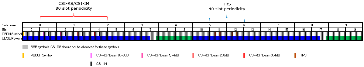
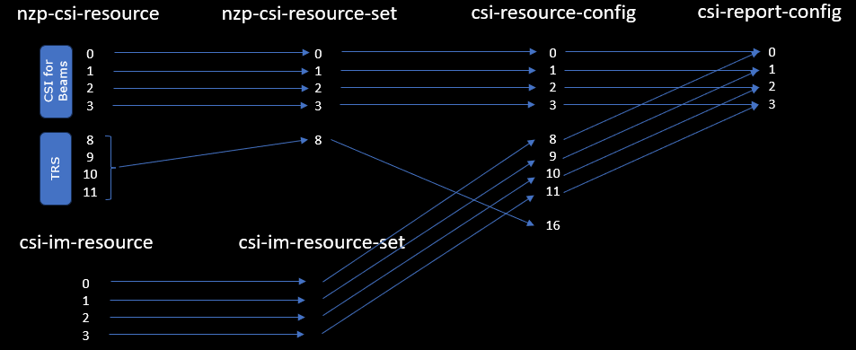
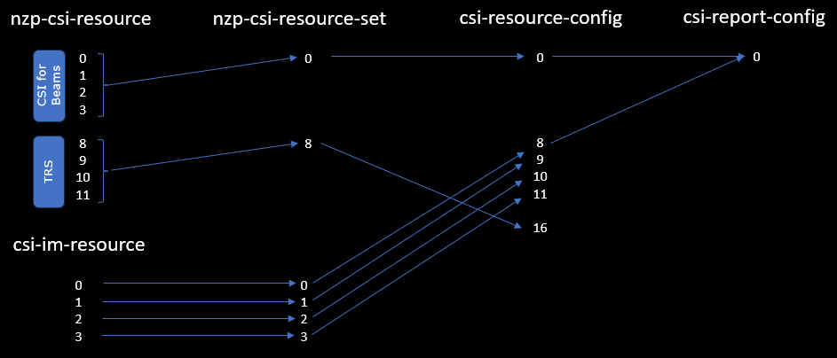
From the time domain resource map, you need to design the entire hierarchy of CSI report from the physical layer csi resource map all the way to csi-report-config. It is important to assign id (the numbers shown on the diagram) in systematically and maintain the consitency, otherwise you may get easily confused when you configure the architecture in RRC message. (
Configuration
The configuration shown here is common configuration for all the subtests belonging to Test 1 and I will not show this configuration repeatedly for every subtest.
I have used gnb-sa-rq-ri-pmi-cqi-4beam.cfg which is copied and modified from gnb-sa.cfg

I am using the default mme, ims config as shown below.

In gnb-sa-rq-ri-pmi-cqi-4beam.cfg it is configured as follows.
In this test, TDD mode is used (NR_TDD 1) and set the downlink number of antenna to 2 (N_ANTENAA_DL 2).
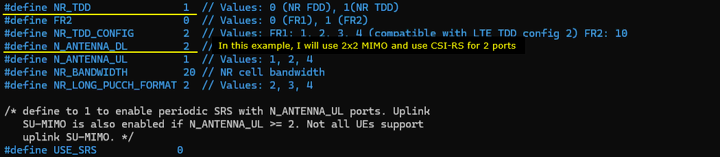
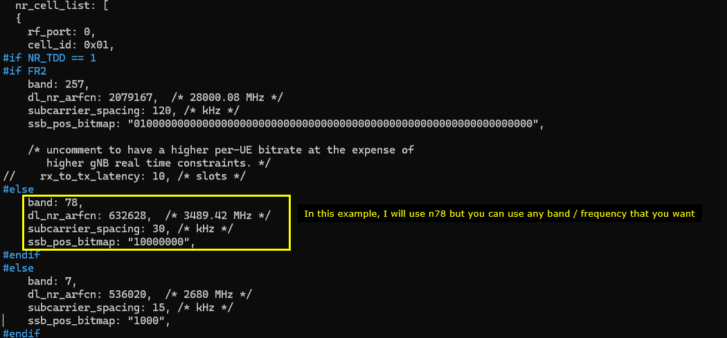
You can use any band you like, but I used the n78 as specified in the default example (
You can use any TDD Pattern, but I used the NR_TDD_CONFIG 2 as in the default example. The only thing to pay attention to is to make it sure that you configure all the CSI RS to be fall into DL symbols defined in the pattern.

This is CSI-RS that is indeded to be mapped to the first beam. n_ports (number of csi antenna port) is 2 and the symbol location is 4(5th OFDM symbol) and relative power(power_confrol_offset) is set to -8 dB. Period is 80 slots and slot offset is set to 1 (
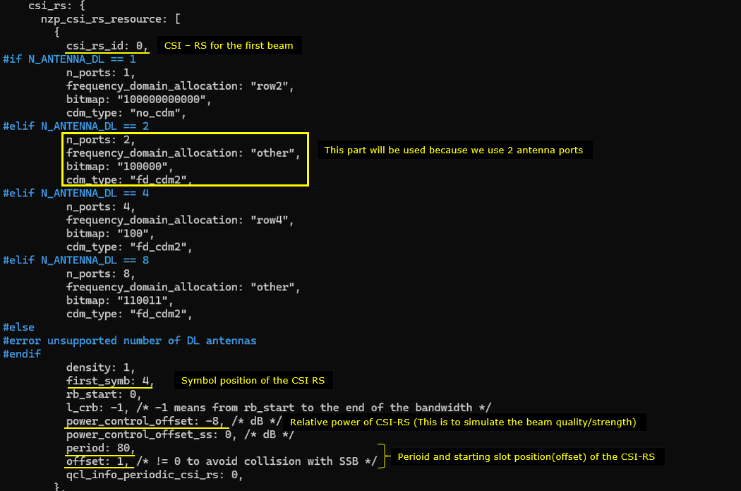
This is CSI-RS that is indeded to be mapped to the second beam. n_ports (number of csi antenna port) is 2 and the symbol location is 4(5th OFDM symbol) and relative power(power_confrol_offset) is set to -4 dB. Period is 80 slots and slot offset is set to 2 (

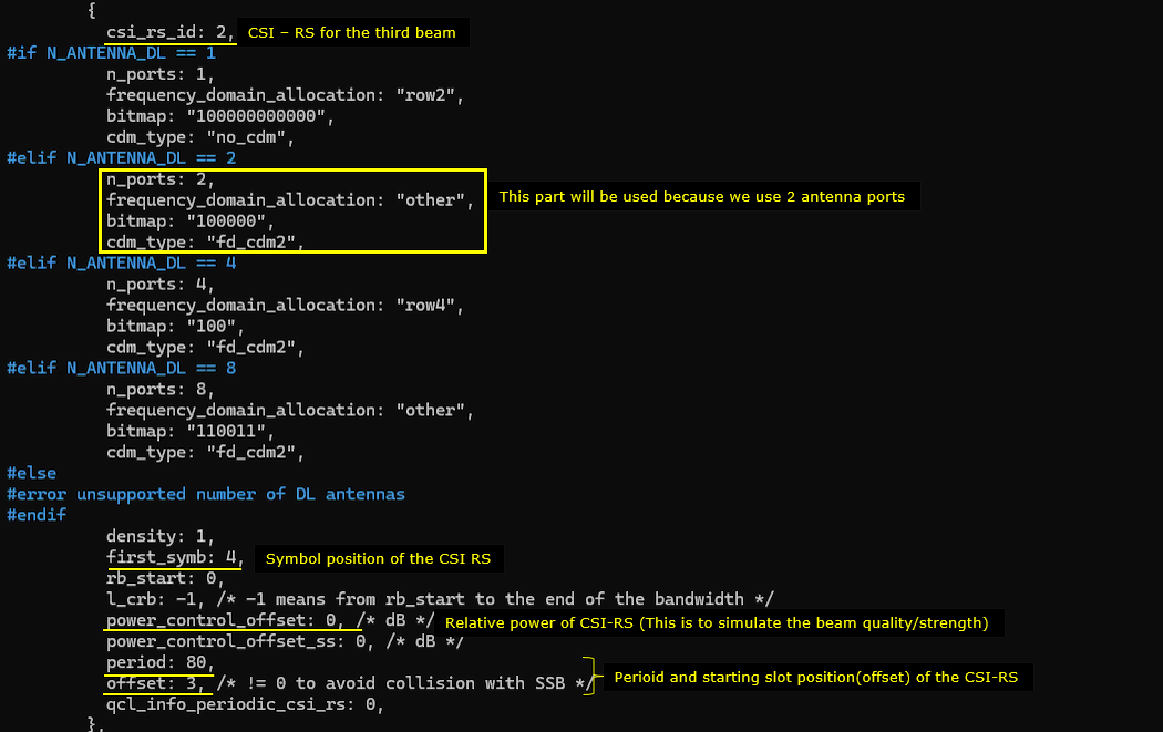
This is CSI-RS that is indeded to be mapped to the second beam. n_ports (number of csi antenna port) is 2 and the symbol location is 4(5th OFDM symbol) and relative power(power_confrol_offset) is set to 0 dB. Period is 80 slots and slot offset is set to 3 (
This is CSI-RS that is indeded to be mapped to the second beam. n_ports (number of csi antenna port) is 2 and the symbol location is 4(5th OFDM symbol) and relative power(power_confrol_offset) is set to 4 dB. Period is 80 slots and slot offset is set to 4 (

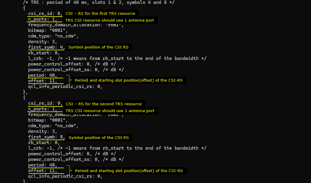
This is for TRS. In this test, a TRS made up of 4 CSI-RS will be used. (
This is the first two TRS CSI-RS configured in slot offset 11 with 40 slot periodicity. The OFDM symbol position of the two TRS is 4 and 8 respectively.
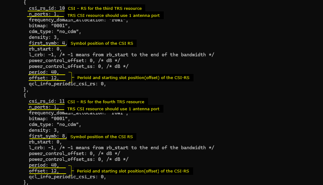
This is the second two TRS CSI-RS configured in slot offset 12 with 40 slot periodicity. The OFDM symbol position of the two TRS is 4 and 8 respectively.
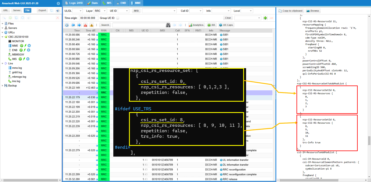
Now group the all the CSI RS into corresponding CSI RS resource sets. I assigned each of the beam CSI (i.e, csi_rs_id 0,1,2,3) into each separate resource set(csi_rs_set_id 0,1,2,3) and put the four TRS CSI RS(csi_rs_id 8,9,10,11) to the same csi rs resource set(csi_rs_set_id 8). (

Now let's define csi_im_resources. I will configure the same number of csi_im_resources as the number of beam csi rs. Each of the csi im will be configured in the same slot as beam csi rs but at different OFDM symbols(non overlapping with beam CSI-RS).
This is the two CSI IM configuration corresponding to the first and second beam CSI-RS.
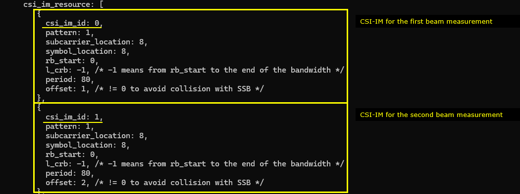
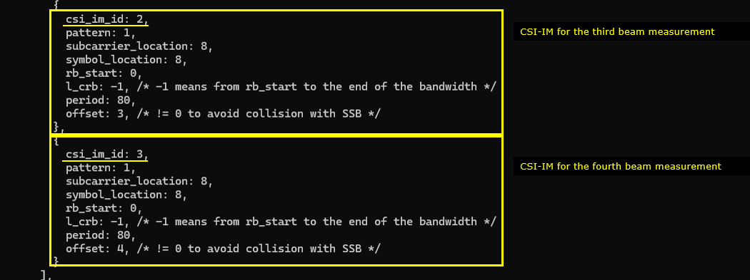
This is the two CSI IM configuration corresponding to the third and fourth beam CSI-RS.
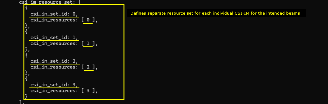
Now let's allocate each of the csi-im resources into corresponding csi im resource sets. I allocate each of the csi im resources (csi_im_id 0,1,2,3) to each individual csi im resource sets (csi_im_set_id 0,1,2,3).
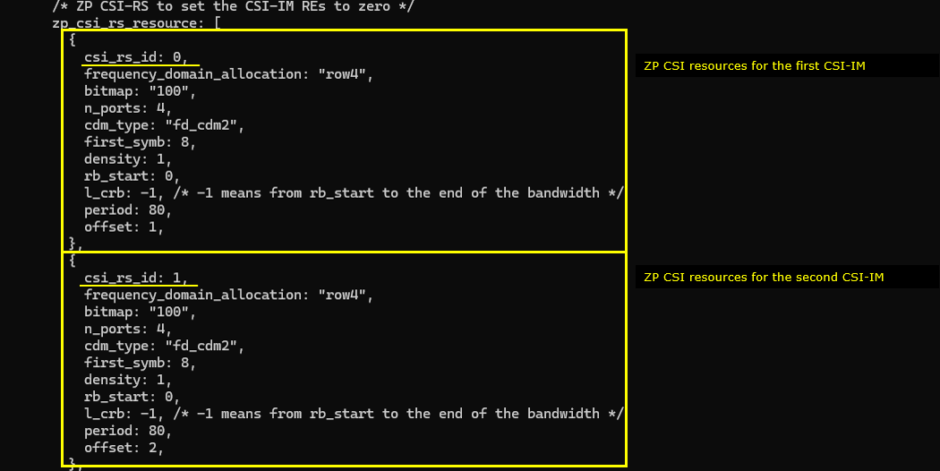
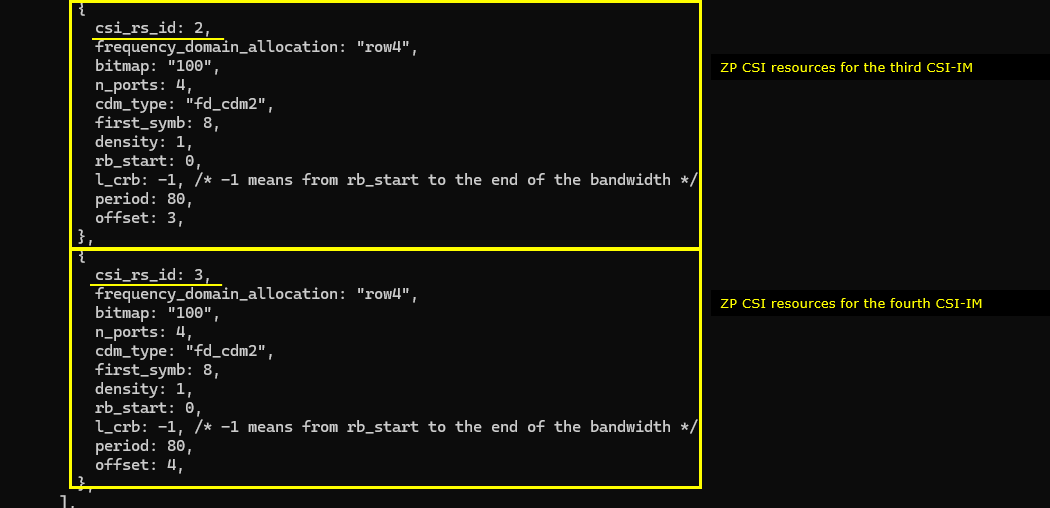
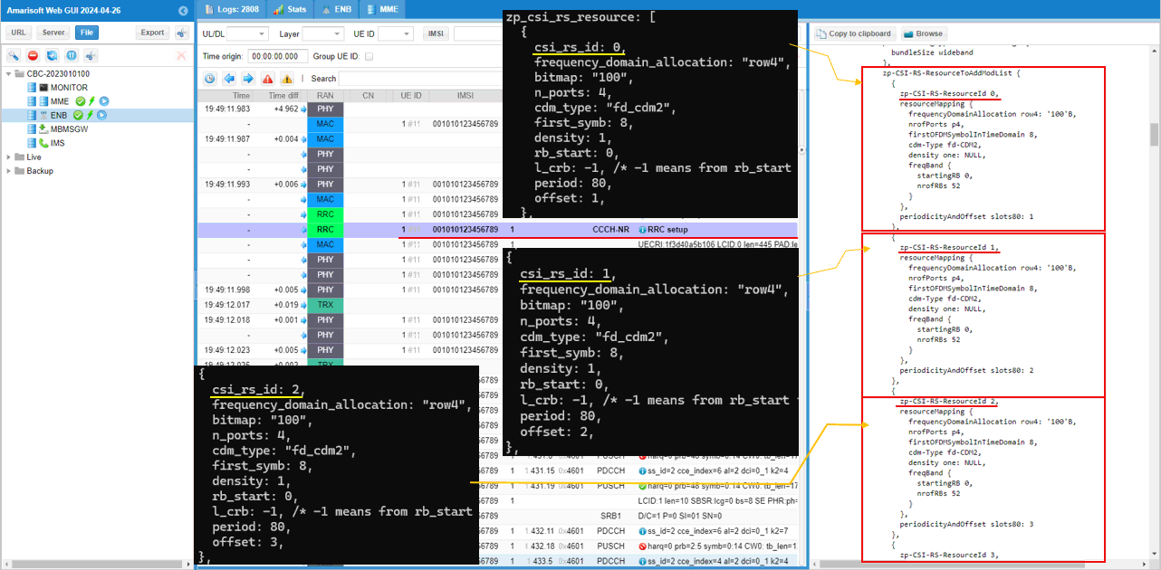
In this test, I have 4 resources for zp csi rs. I set this to overlap with the four csi im REs to set the REs to be zero.
This is configurations for the first and second zp csi rs (csi_rs_id 0 and 1).
This is configurations for the third and fourth zp csi rs (csi_rs_id 2 and 3).
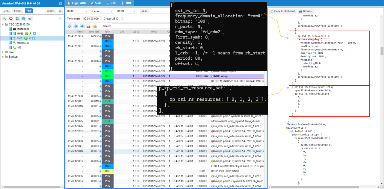
Then I allocated the four zp csi rs into one csi rs resource set.

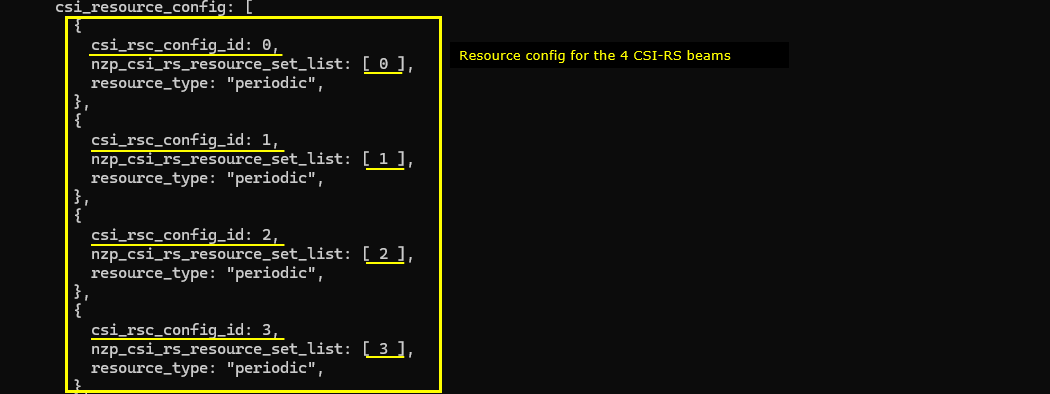
Now let's construct csi resource config from all the csi rs resource sets that we created above.
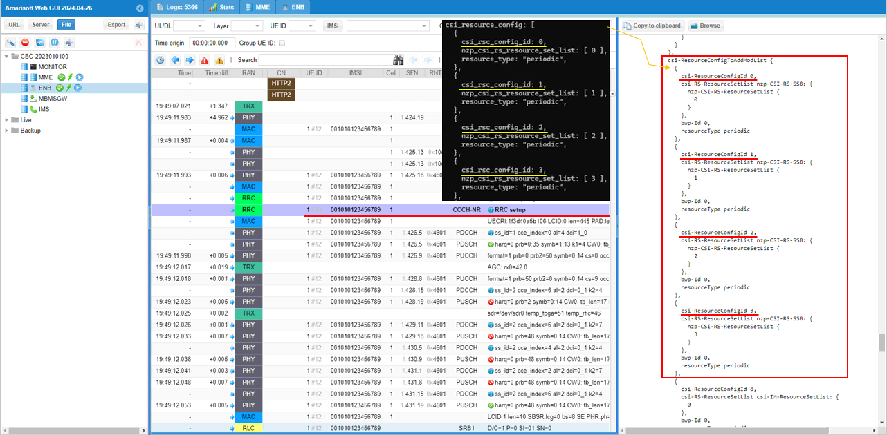
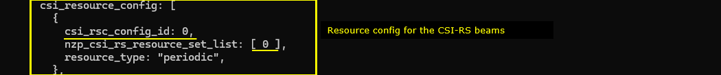
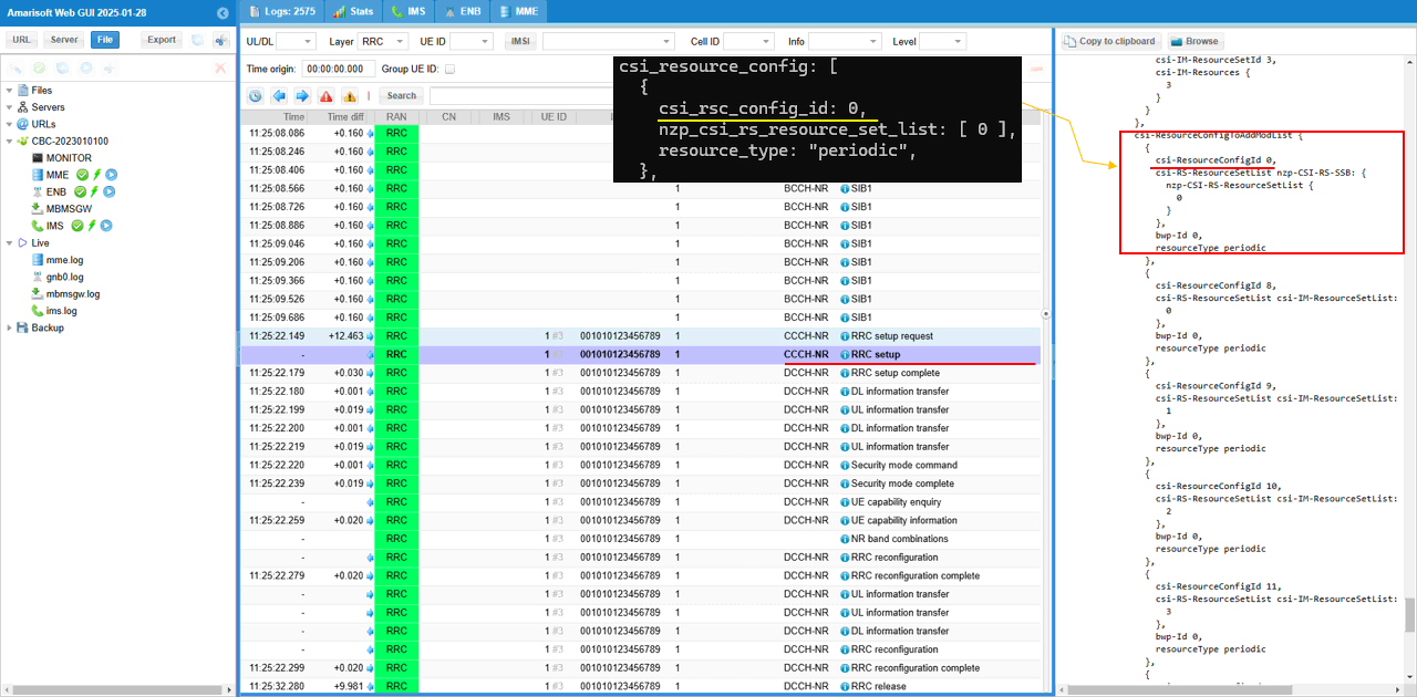
First, I created 4 csi resource configs (csi_rsc_config_id 0,1,2,3) from the four nzp_csi_rs_resource_set 0,1,2,3 and set the resource_type to "periodic".
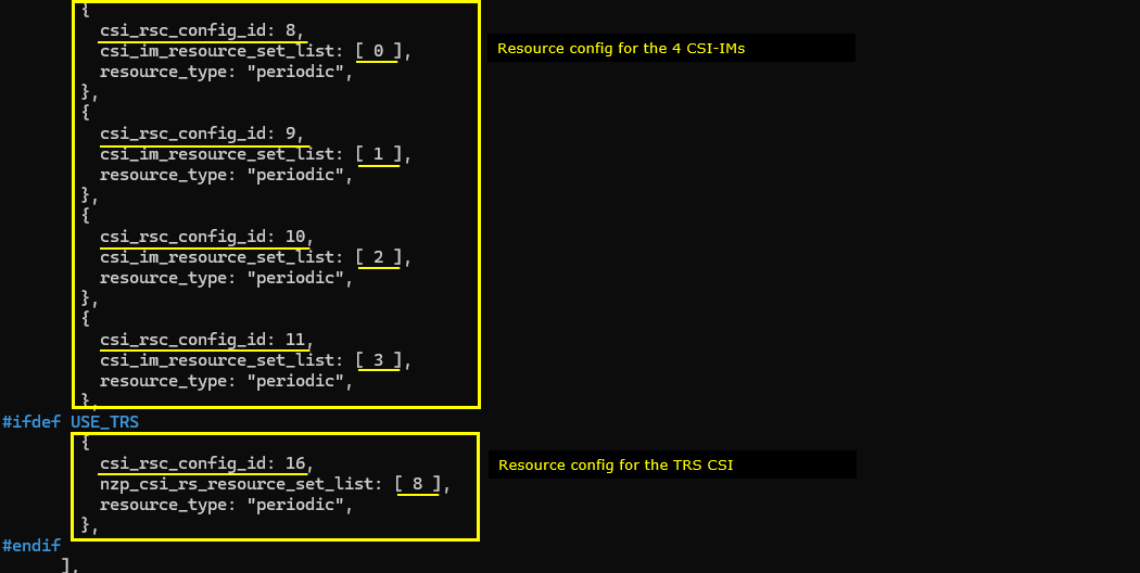
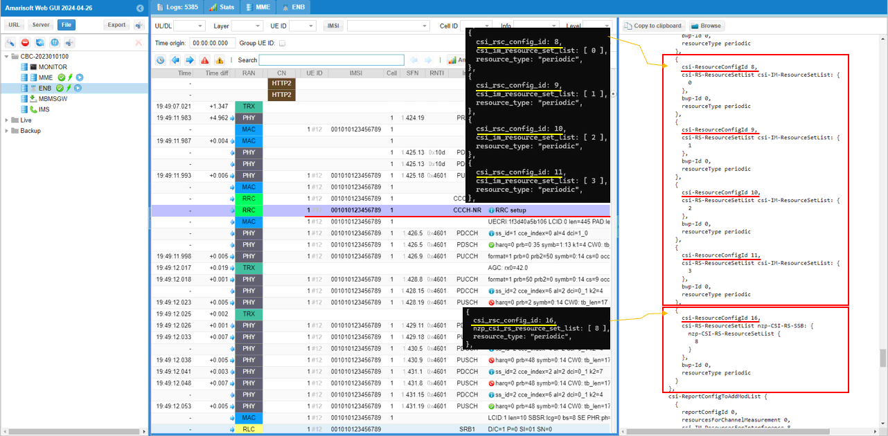
Then, I created another 4 csi resource configs (csi_rsc_config_id 8,9,10,11) from the four csi_im_resource_set 0,1,2,3 and set the resource_type to "periodic". (
And then I created the last csi rsc config(csi_rsc_config_id 16) for TRS CSI.
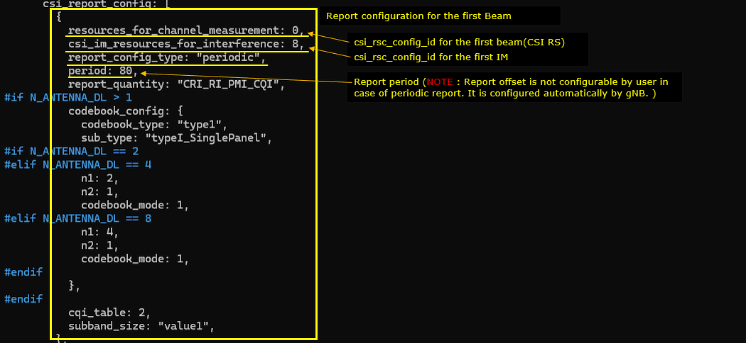
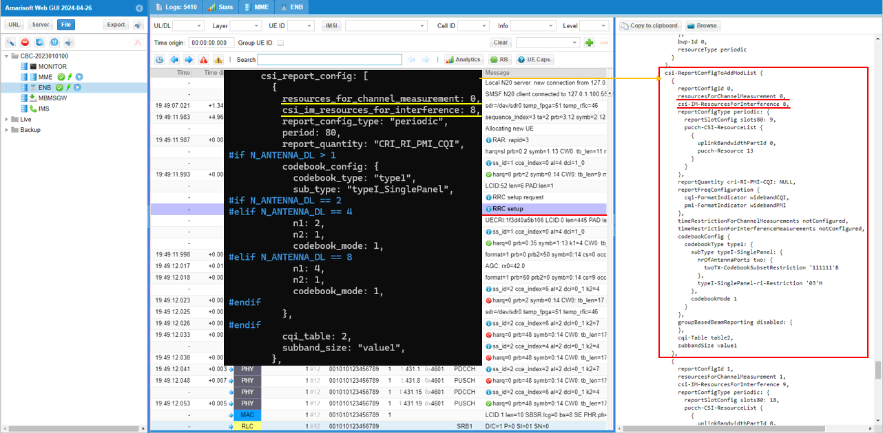
As the last step, I will create the four csi report configurations (csi_report_config) for each of the CSI RS beams. Each of the report config has resources_for_channel_measuremet which points to the csi_rsc_config_id for the measurement and csi_im_resources_for_interference which points to csi_rsc_config_id for the corresponding CSI IM.
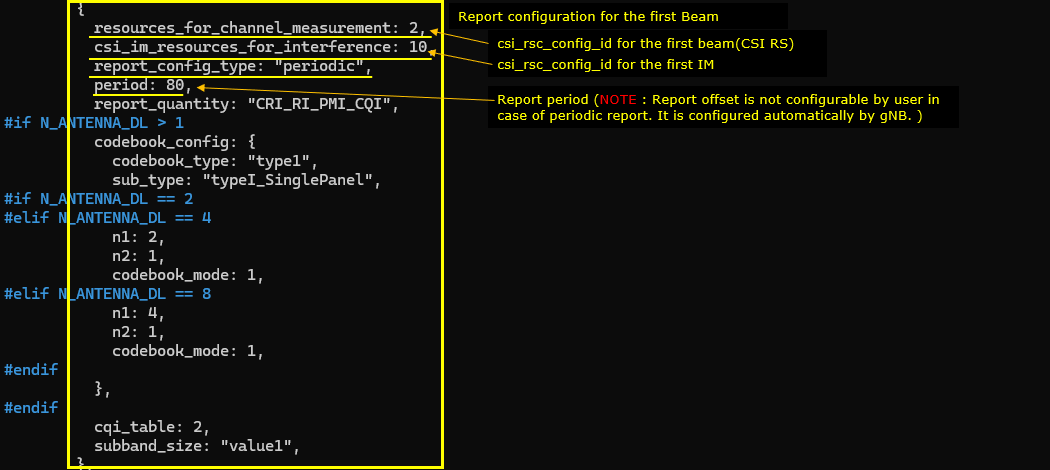
This is the csi_report_config for the first CSI RS. resources_for_channel_measuremet is mapped to csi_rsc_config_id 0 and csi_im_resources_for_interference is mapped to csi_rsc_config_id 8. In this test, period is set to 80 slots (
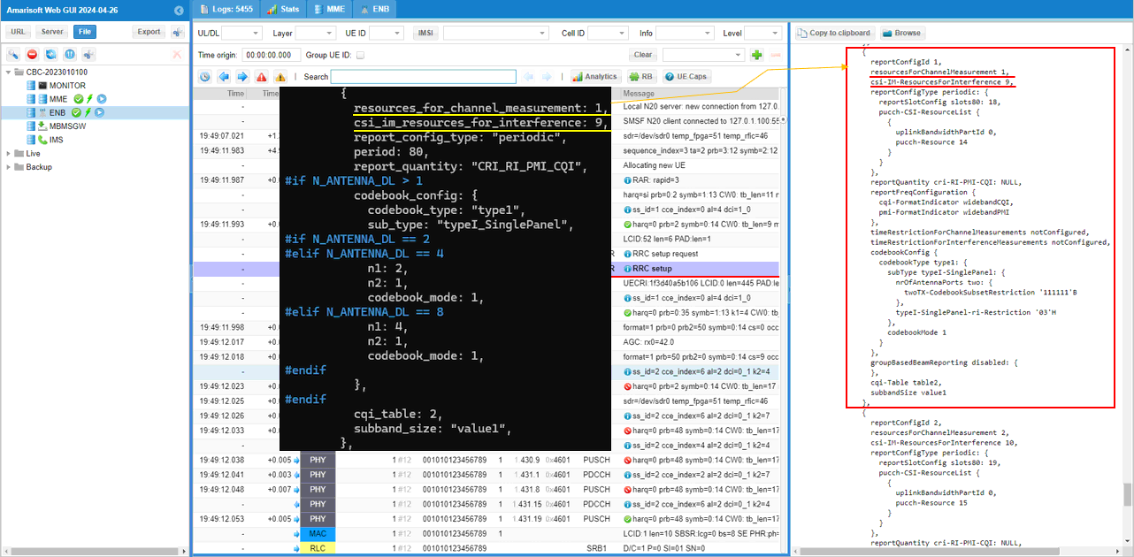
This is the csi_report_config for the second CSI RS. resources_for_channel_measuremet is mapped to csi_rsc_config_id 1 and csi_im_resources_for_interference is mapped to csi_rsc_config_id 9. In this test, period is set to 80 slots (

This is the csi_report_config for the third CSI RS. resources_for_channel_measuremet is mapped to csi_rsc_config_id 2 and csi_im_resources_for_interference is mapped to csi_rsc_config_id 10. In this test, period is set to 80 slots (
This is the csi_report_config for the first CSI RS. resources_for_channel_measuremet is mapped to csi_rsc_config_id 3 and csi_im_resources_for_interference is mapped to csi_rsc_config_id 11. In this test, period is set to 80 slots (
Perform the Test
Operation for this test is very simple. The difficult part is verfication with the log and other methods.
First check with basic configuration of the cell with 'cell phy' command and see if the cell is configured as you intended (

Then run 't' command, power on UE and wait until the call is established.
Log Analysis
This is just for showing the association between the configuration shown above and IE (Information Elements) in RRC and see if UE report CSI RS as you intended.
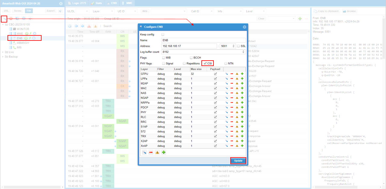
Before you start logging, I would suggest you to set every items in 'debug' mode for ENB to collect full stack trace of the enb and check 'CSI' to display the decoded CSI report(bitmap) in more human readable format.
First check on the default PDCCH TCI states for PDCCH. You see only one tci-state with reference signal mapped to ssb 0. This is not what is set in the configuration file. It is the configuration automatically set by gNB (
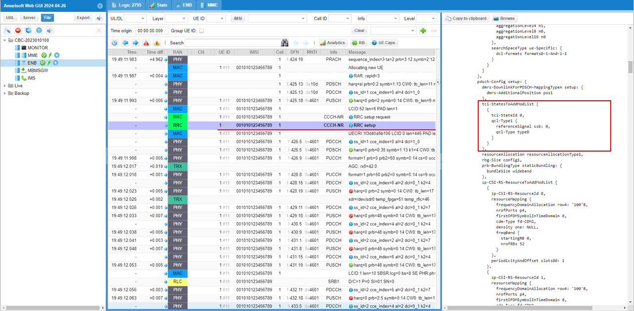
Followings are the three zp-CSI-RS out of 4 zp-CSI-RS set in the configuration file (csi_rs_id 0,1,2,3) and configured in zp-CSI-RS-ResourceToAddModList in RRC message.
Following is the fourth zp-CSI-RS set in the configuration file (csi_rs_id 0,1,2,3) and configured in zp-CSI-RS-ResourceToAddModList in RRC message..
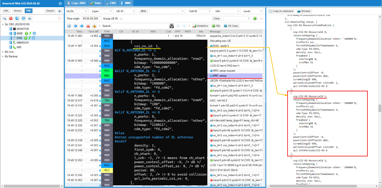
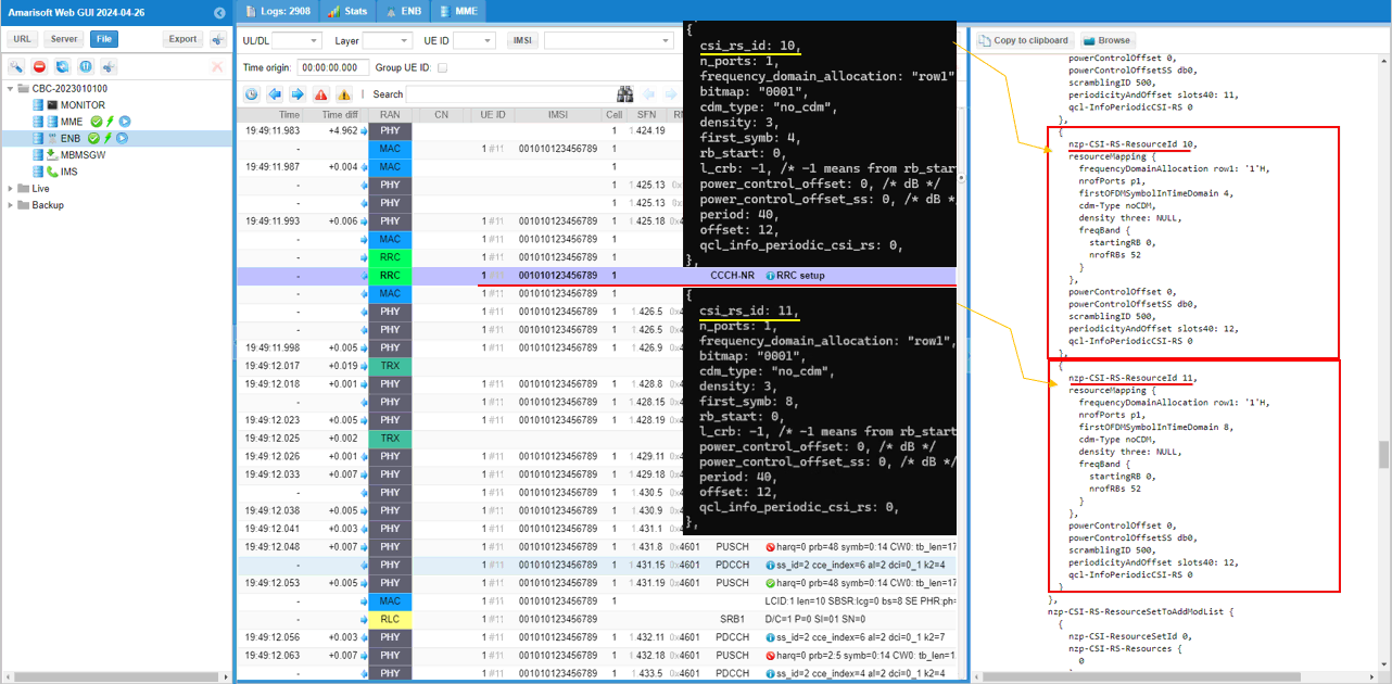
Following is the first CSI-RS resources for the first beam set in the configuration file which is mapped to nzp-CSI-RS-ResourceId 0 of nzp-CSI-RS-ResourceToAddModList in RRC.
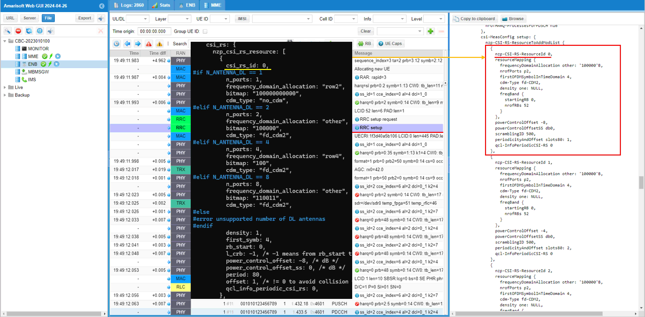
Following is the first CSI-RS resources for the second beam set in the configuration file which is mapped to nzp-CSI-RS-ResourceId 1 of nzp-CSI-RS-ResourceToAddModList in RRC.
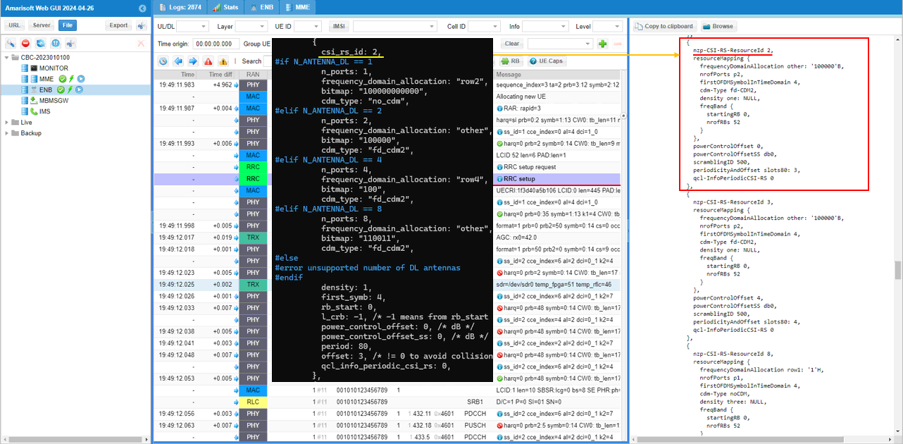
Following is the first CSI-RS resources for the third beam set in the configuration file which is mapped to nzp-CSI-RS-ResourceId 2 of nzp-CSI-RS-ResourceToAddModList in RRC.
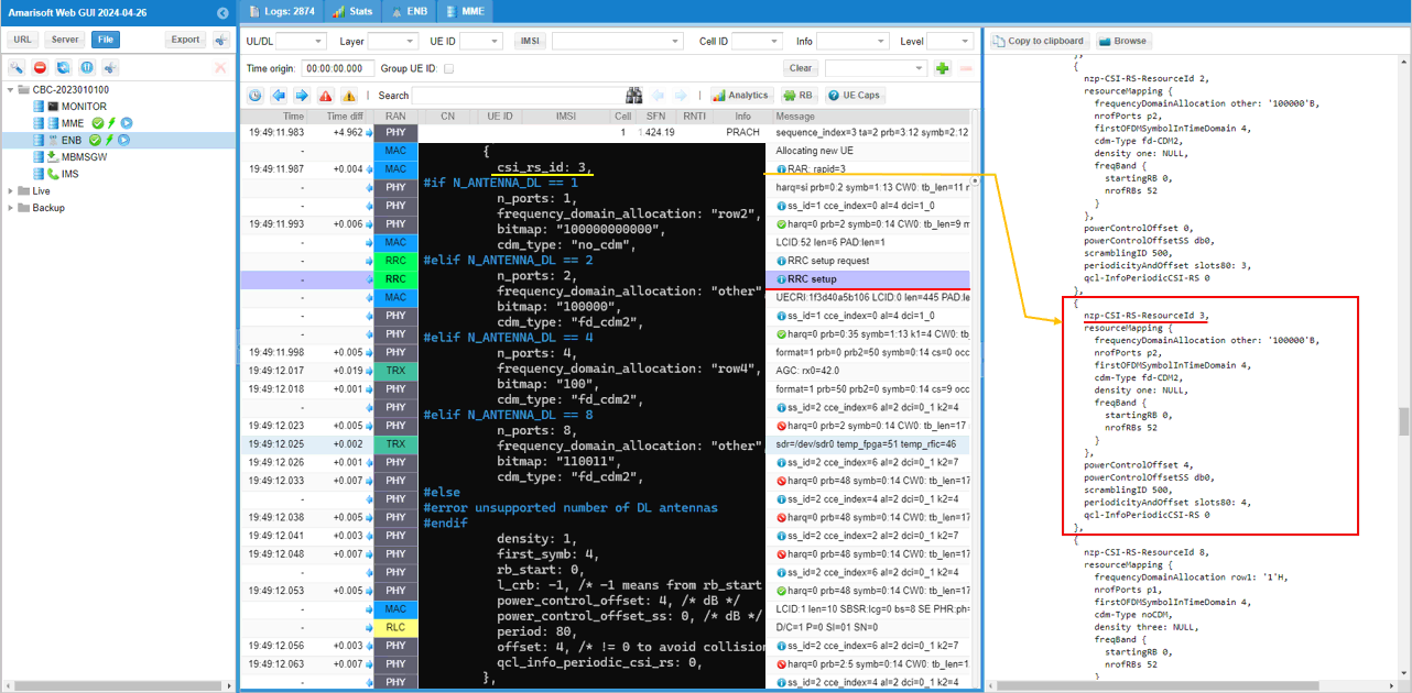
Following is the first CSI-RS resources for the fourth beam set in the configuration file which is mapped to nzp-CSI-RS-ResourceId 3 of nzp-CSI-RS-ResourceToAddModList in RRC.
Followings are the first two CSI-RS resources for TRS set in the configuration file which is mapped to nzp-CSI-RS-ResourceId 8,9 of nzp-CSI-RS-ResourceToAddModList in RRC.
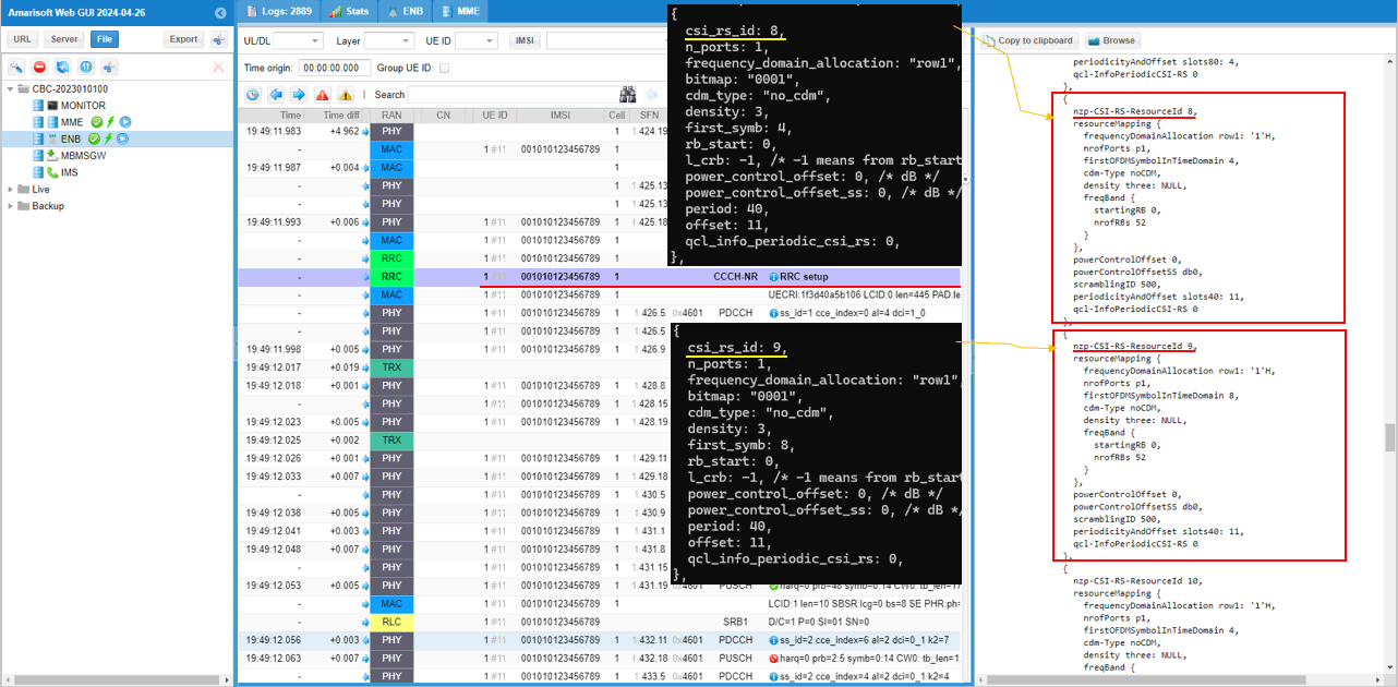
Followings are the second two CSI-RS resources for TRS set in the configuration file which is mapped to nzp-CSI-RS-ResourceId 10,11 of nzp-CSI-RS-ResourceToAddModList in RRC.
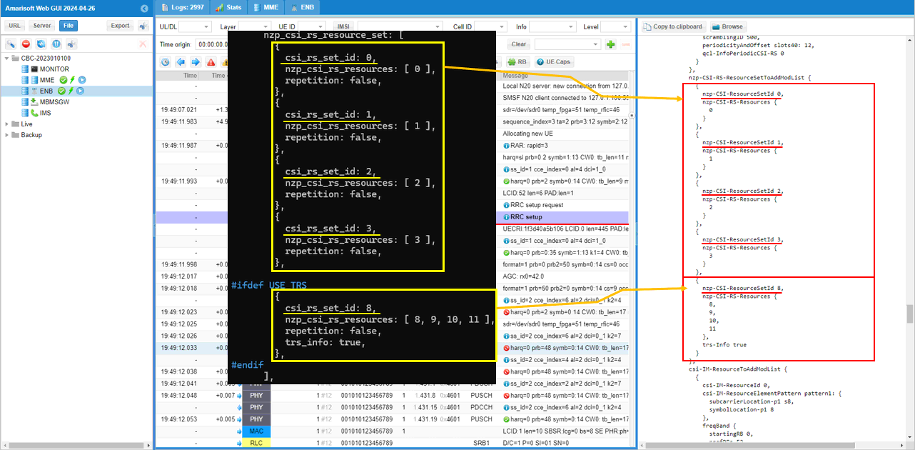
Followings are CSI-RS-ResourceSets constructed out of nzp CSI RS resources configured above. As you see, each of the beam CSI (i.e, csi_rs_id 0,1,2,3) is grouped into each separate resource set(csi_rs_set_id 0,1,2,3) and the four TRS CSI RS(csi_rs_id 8,9,10,11) are groupled to the same csi rs resource set(csi_rs_set_id 8).
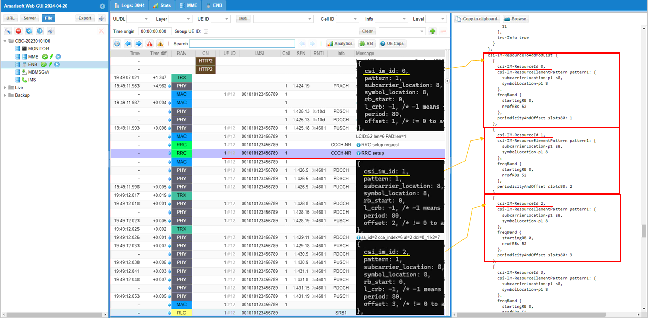
Followings are the three (out of 4) CSI-IM resources set in the configuration file which is mapped to CSI-IM-ResourceId 0,1,2 of CSI-IM-ResourceToAddModList in RRC.
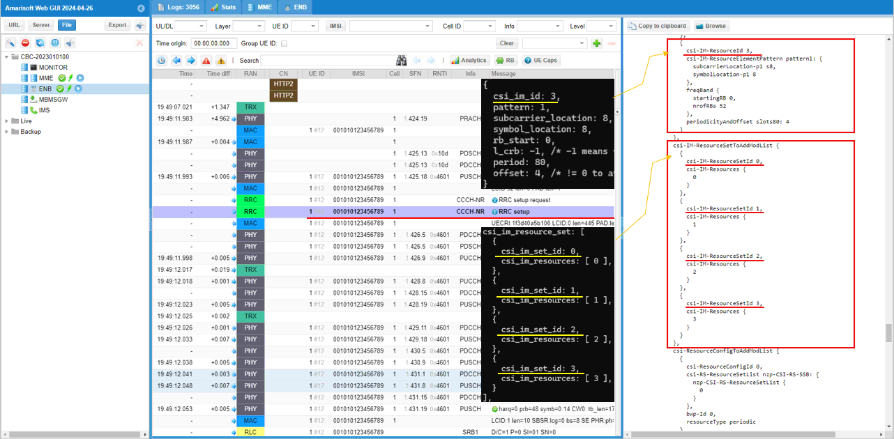
Followings are the fourth (out of 4) CSI-IM resources set in the configuration file which is mapped to CSI-IM-ResourceId 3 of CSI-IM-ResourceToAddModList and csi-IM-ResourceSets constructed out of the 4 csi-IM-Resources in RRC.
Following is the 4 csi-ResourceConfig constructed from the CSI-RS Resource sets configured above. (csi-ResourceConfigId 0,1,2,3) in csi-ResourceConfigToAddModList)
Following is the 4 csi-ResourceConfig constructed from the CSI-IM Resource sets configured above. (csi-ResourceConfigId 8,9,10,11) and one csi-ResourceConfig(csi-ResourceConfigId 16) constructed from TRS resource set in csi-ResourceConfigToAddModList.
Now comes the last stage of the configuration which is CSI Report Configuration.
This is the report configuration for the first CSI beam which is associated with CSI RS config 0 for signal measurement and 8 for interference measurement. The codebook is set to type1 and typeI-SinglePanel. Period is 80 slots and slot offset is set to 9 (
This is the report configuration for the second CSI beam which is associated with CSI RS config 1 for signal measurement and 9 for interference measurement. The codebook is set to type1 and typeI-SinglePanel. Period is 80 slots and slot offset is set to 18 (
This is the report configuration for the third CSI beam which is associated with CSI RS config 2 for signal measurement and 10 for interference measurement. The codebook is set to type1 and typeI-SinglePanel. Period is 80 slots and slot offset is set to 19 (
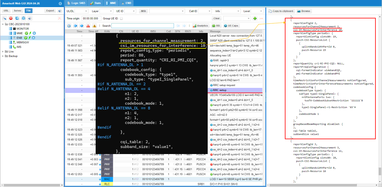
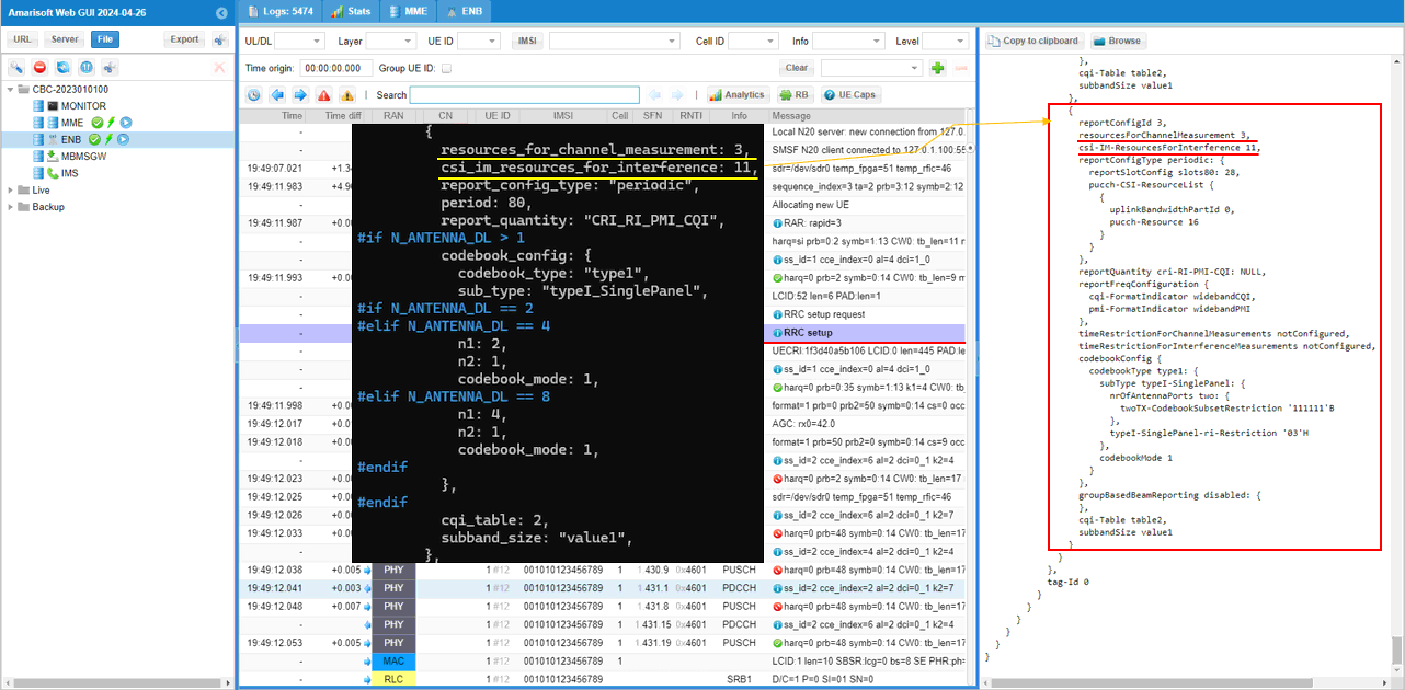
This is the report configuration for the first CSI beam which is associated with CSI RS config 3 for signal measurement and 11 for interference measurement. The codebook is set to type1 and typeI-SinglePanel. Period is 80 slots and slot offset is set to 20 (
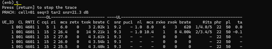
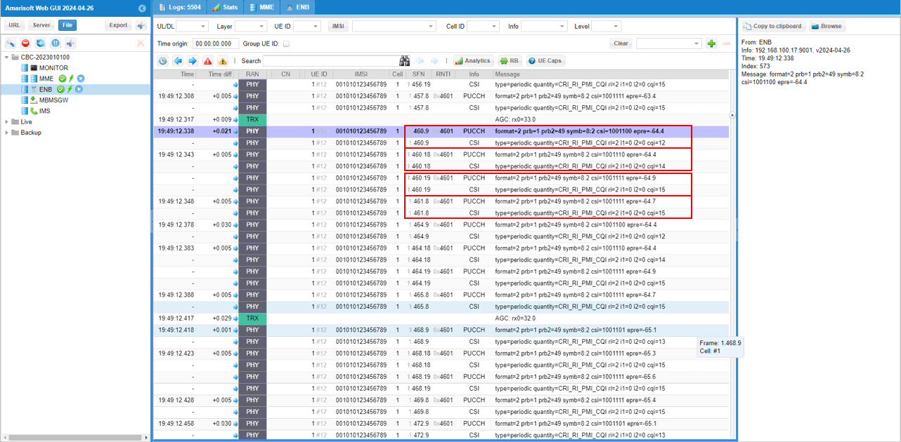
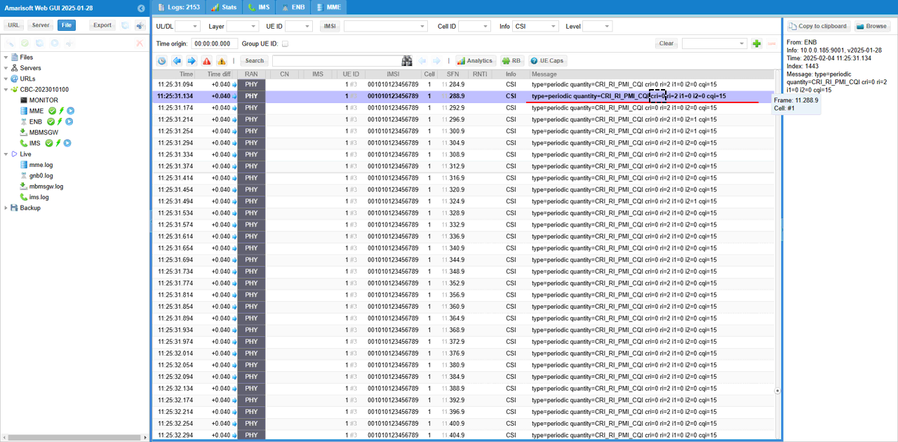
Once everything configured properly and the call is setup, you should get CSI report as follows. You would notice that cqi value varies for each measurement CSI-RS which is transmitted at different power.
Visualization of CSI RS
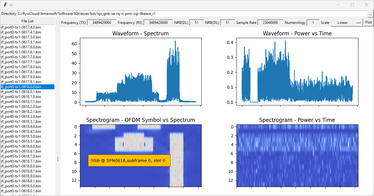
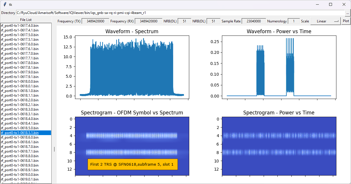
Here I will show you on how to visualize CSI-RS physical resources in various different format. It is not possible to visualize the beam itself, but you can visualize exact physical resources for each CSI RS in this way. To do this, I am using the tool trx-iq-dump.js which is explained in detail in this tutorial. (
This slot shows the SSB at the SFN 0618, subframe 0, slot 0. In this tutorial, SSB is not used for the beam management, but always good to identify the SSB as a reference.
This shows the first two TRS CSI-RS at SFN 0618, subframe 5, slot 1.
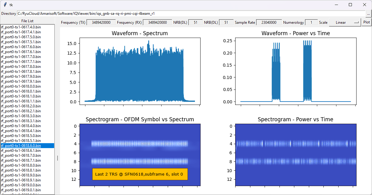
This shows the last two TRS CSI-RS at SFN 0618, subframe 6, slot 0.
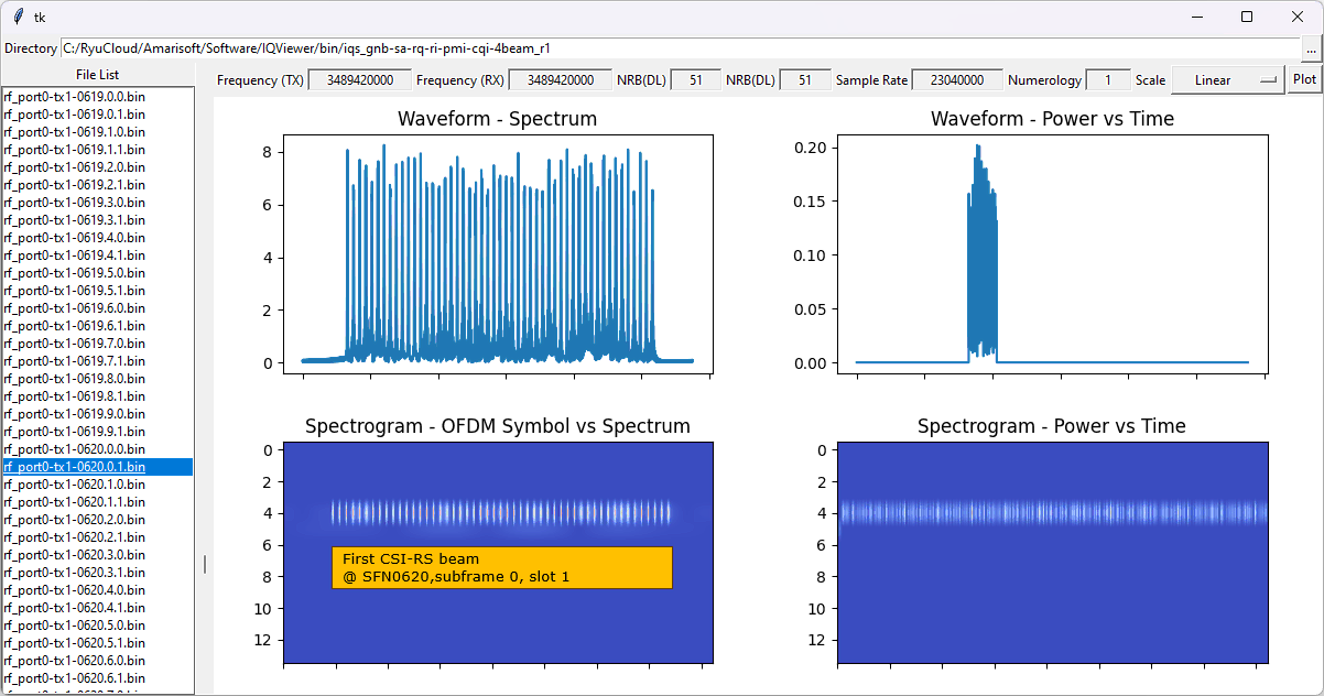
This shows the first CSI-RS for beam management at SFN 0620, subframe 0, slot 1. This is the first CSI-RS out of the 4 CSI-RS that will be used for beam report.
This shows the second CSI-RS for beam management at SFN 0620, subframe 1, slot 0. This is the second CSI-RS out of the 4 CSI-RS that will be used for beam report.

This shows the third CSI-RS for beam management at SFN 0620, subframe 1, slot 1. This is the third CSI-RS out of the 4 CSI-RS that will be used for beam report.

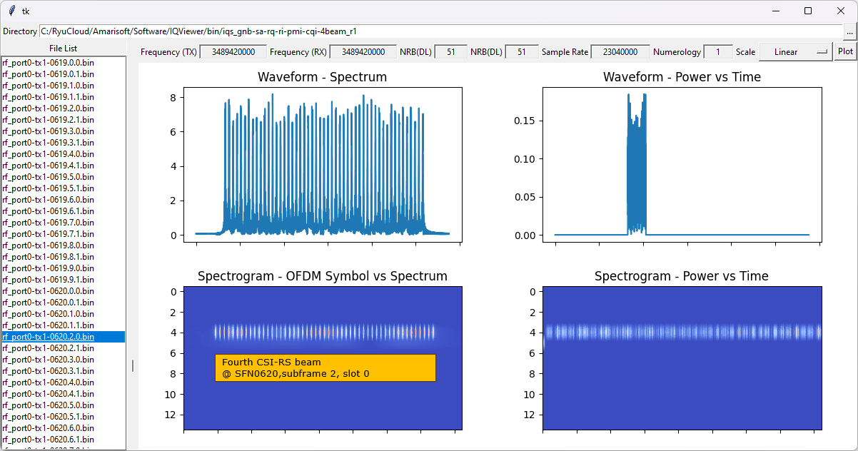
This shows the fourth CSI-RS for beam management at SFN 0620, subframe 2, slot 0. This is the fourth CSI-RS out of the 4 CSI-RS that will be used for beam report.
Test 2 : Periodic CSI Report with CRI
In this test, I will show you how to configure manually the periodic CSI report for the 4 different CSI-RS (2 ports each). In this test, the four different CSI-RS is associated to a single resource set which will be used for single CSI report. In this case, UE is expected to measure all of the beams and report the best beam with beam id(CRI) and the measurement result in a single report
As you may know if you have tried to configure this kind of measurement before, you would know it is extremly complicated and confusing to configure those multiple CSI RS report manually. My personal tips to create a test plan for this kind of case is to draw a few diagram clearly showing what is intended to do. In my case, I usually draw two diagrams as shown below.
The first diagram that I often draw is to show the physical resource allocation for all the CSI-RS / CSI-IM in time domain as shown below. It would be even better if you draw physical resource map for both time domain and frequency domain, but it may be too much to do. So I usually draw time-domain resource map only.
From the time domain resource map, you need to design the entire hierarchy of CSI report from the physical layer csi resource map all the way to csi-report-config. It is important to assign id (the numbers shown on the diagram) in systematically and maintain the consitency, otherwise you may get easily confused when you configure the architecture in RRC message. (
Configuration
The configuration shown here is common configuration for all the subtests belonging to Test 1 and I will not show this configuration repeatedly for every subtest.
I have used gnb-sa-rq-cri-ri-pmi-cqi-4beam.cfg which is copied and modified from gnb-sa.cfg

I am using the default mme, ims config as shown below.
In gnb-sa-rq-cri-ri-pmi-cqi-4beam.cfg it is configured as follows.
In this test, TDD mode is used (NR_TDD 1) and set the downlink number of antenna to 2 (N_ANTENAA_DL 2).
You can use any band you like, but I used the n78 as specified in the default example (
You can use any TDD Pattern, but I used the NR_TDD_CONFIG 2 as in the default example. The only thing to pay attention to is to make it sure that you configure all the CSI RS to be fall into DL symbols defined in the pattern.
This is CSI-RS that is indeded to be mapped to the first beam. n_ports (number of csi antenna port) is 2 and the symbol location is 4(5th OFDM symbol) and relative power(power_confrol_offset) is set to -8 dB. Period is 80 slots and slot offset is set to 1 (
This is CSI-RS that is indeded to be mapped to the second beam. n_ports (number of csi antenna port) is 2 and the symbol location is 4(5th OFDM symbol) and relative power(power_confrol_offset) is set to -4 dB. Period is 80 slots and slot offset is set to 2 (
This is CSI-RS that is indeded to be mapped to the second beam. n_ports (number of csi antenna port) is 2 and the symbol location is 4(5th OFDM symbol) and relative power(power_confrol_offset) is set to 0 dB. Period is 80 slots and slot offset is set to 3 (
This is CSI-RS that is indeded to be mapped to the second beam. n_ports (number of csi antenna port) is 2 and the symbol location is 4(5th OFDM symbol) and relative power(power_confrol_offset) is set to 4 dB. Period is 80 slots and slot offset is set to 4 (
This is for TRS. In this test, a TRS made up of 4 CSI-RS will be used. (
This is the first two TRS CSI-RS configured in slot offset 11 with 40 slot periodicity. The OFDM symbol position of the two TRS is 4 and 8 respectively.
This is the second two TRS CSI-RS configured in slot offset 12 with 40 slot periodicity. The OFDM symbol position of the two TRS is 4 and 8 respectively.
Now group the all the CSI RS into corresponding CSI RS resource sets. I assigned each of the beam CSI (i.e, csi_rs_id 0,1,2,3) into each separate resource set(csi_rs_set_id 0,1,2,3) and put the four TRS CSI RS(csi_rs_id 8,9,10,11) to the same csi rs resource set(csi_rs_set_id 8). (
Now let's define csi_im_resources. I will configure the same number of csi_im_resources as the number of beam csi rs. Each of the csi im will be configured in the same slot as beam csi rs but at different OFDM symbols(non overlapping with beam CSI-RS).
This is the two CSI IM configuration corresponding to the first and second beam CSI-RS.
This is the two CSI IM configuration corresponding to the third and fourth beam CSI-RS.
Now let's allocate each of the csi-im resources into corresponding csi im resource sets. I allocate each of the csi im resources (csi_im_id 0,1,2,3) to each individual csi im resource sets (csi_im_set_id 0,1,2,3).
In this test, I have 4 resources for zp csi rs. I set this to overlap with the four csi im REs to set the REs to be zero.
This is configurations for the first and second zp csi rs (csi_rs_id 0 and 1).
This is configurations for the third and fourth zp csi rs (csi_rs_id 2 and 3).
Then I allocated the four zp csi rs into one csi rs resource set.
Now let's construct csi resource config from all the csi rs resource sets that we created above.
First, I created one csi resource configs (csi_rsc_config_id 0) from the four nzp_csi_rs_resource_set 0 and set the resource_type to "periodic".
Then, I created another 4 csi resource configs (csi_rsc_config_id 8,9,10,11) from the four csi_im_resource_set 0,1,2,3 and set the resource_type to "periodic". (
And then I created the last csi rsc config(csi_rsc_config_id 16) for TRS CSI.
As the last step, I will create the four csi report configurations (csi_report_config) for each of the CSI RS beams. Each of the report config has resources_for_channel_measuremet which points to the csi_rsc_config_id for the measurement and csi_im_resources_for_interference which points to csi_rsc_config_id for the corresponding CSI IM.
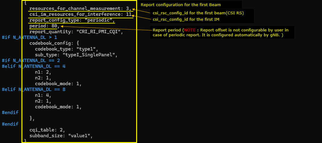
This is the csi_report_config for the first CSI RS. resources_for_channel_measuremet is mapped to csi_rsc_config_id 0 and csi_im_resources_for_interference is mapped to csi_rsc_config_id 8. In this test, period is set to 80 slots (
Perform the Test
Operation for this test is very simple. The difficult part is verfication with the log and other methods.
First check with basic configuration of the cell with 'cell phy' command and see if the cell is configured as you intended (
Then run 't' command, power on UE and wait until the call is established.
Log Analysis
This is just for showing the association between the configuration shown above and IE (Information Elements) in RRC and see if UE report CSI RS as you intended.
Before you start logging, I would suggest you to set every items in 'debug' mode for ENB to collect full stack trace of the enb and check 'CSI' to display the decoded CSI report(bitmap) in more human readable format.
First check on the default PDCCH TCI states for PDCCH. You see only one tci-state with reference signal mapped to ssb 0. This is not what is set in the configuration file. It is the configuration automatically set by gNB (
Followings are the three zp-CSI-RS out of 4 zp-CSI-RS set in the configuration file (csi_rs_id 0,1,2,3) and configured in zp-CSI-RS-ResourceToAddModList in RRC message.
Following is the fourth zp-CSI-RS set in the configuration file (csi_rs_id 0,1,2,3) and configured in zp-CSI-RS-ResourceToAddModList in RRC message..
Following is the first CSI-RS resources for the first beam set in the configuration file which is mapped to nzp-CSI-RS-ResourceId 0 of nzp-CSI-RS-ResourceToAddModList in RRC.
Following is the first CSI-RS resources for the second beam set in the configuration file which is mapped to nzp-CSI-RS-ResourceId 1 of nzp-CSI-RS-ResourceToAddModList in RRC.
Following is the first CSI-RS resources for the third beam set in the configuration file which is mapped to nzp-CSI-RS-ResourceId 2 of nzp-CSI-RS-ResourceToAddModList in RRC.
Following is the first CSI-RS resources for the fourth beam set in the configuration file which is mapped to nzp-CSI-RS-ResourceId 3 of nzp-CSI-RS-ResourceToAddModList in RRC.
Followings are the first two CSI-RS resources for TRS set in the configuration file which is mapped to nzp-CSI-RS-ResourceId 8,9 of nzp-CSI-RS-ResourceToAddModList in RRC.
Followings are the second two CSI-RS resources for TRS set in the configuration file which is mapped to nzp-CSI-RS-ResourceId 10,11 of nzp-CSI-RS-ResourceToAddModList in RRC.
Followings are CSI-RS-ResourceSets constructed out of nzp CSI RS resources configured above. As you see, four CSI RS (i.e, csi_rs_id 0,1,2,3) is grouped into single resource set(csi_rs_set_id 0) and the four TRS CSI RS(csi_rs_id 8,9,10,11) are groupled to the same csi rs resource set(csi_rs_set_id 8).
Followings are the three (out of 4) CSI-IM resources set in the configuration file which is mapped to CSI-IM-ResourceId 0,1,2 of CSI-IM-ResourceToAddModList in RRC.
Followings are the fourth (out of 4) CSI-IM resources set in the configuration file which is mapped to CSI-IM-ResourceId 3 of CSI-IM-ResourceToAddModList and csi-IM-ResourceSets constructed out of the 4 csi-IM-Resources in RRC.
Following is the csi-ResourceConfig constructed from the CSI-RS Resource sets configured above. (csi-ResourceConfigId 0) in csi-ResourceConfigToAddModList)
Following is the 4 csi-ResourceConfig constructed from the CSI-IM Resource sets configured above. (csi-ResourceConfigId 8,9,10,11) and one csi-ResourceConfig(csi-ResourceConfigId 16) constructed from TRS resource set in csi-ResourceConfigToAddModList.
Now comes the last stage of the configuration which is CSI Report Configuration.
This is the report configuration for the first CSI beam which is associated with CSI RS config 0 for signal measurement and 8 for interference measurement. The codebook is set to type1 and typeI-SinglePanel. Period is 80 slots and slot offset is set to 9 (
Once everything configured properly and the call is setup, you should get CSI report as follows. You would notice that cri value is reported.
RRC / NAS Signaling
RrcSetup (SA)
: This is the RrcSetup message sent by gNB to configure NR SA. (
{
message c1: rrcSetup: {
rrc-TransactionIdentifier 0,
criticalExtensions rrcSetup: {
radioBearerConfig {
...
},
masterCellGroup {
cellGroupId 0,
rlc-BearerToAddModList {
...
},
mac-CellGroupConfig {
...
},
physicalCellGroupConfig {
pdsch-HARQ-ACK-Codebook dynamic
},
spCellConfig {
spCellConfigDedicated {
initialDownlinkBWP {
pdcch-Config setup: {
...
},
pdsch-Config setup: {
dmrs-DownlinkForPDSCH-MappingTypeA setup: {
dmrs-AdditionalPosition pos1
},
tci-StatesToAddModList {
{
tci-StateId 0,
qcl-Type1 {
referenceSignal ssb: 0,
qcl-Type typeD
}
},
{
tci-StateId 1,
qcl-Type1 {
referenceSignal csi-rs: 0,
qcl-Type typeD
}
},
{
tci-StateId 2,
qcl-Type1 {
referenceSignal ssb: 0,
qcl-Type typeC
},
qcl-Type2 {
referenceSignal csi-rs: 0,
qcl-Type typeD
}
}
},
...
zp-CSI-RS-ResourceToAddModList {
{
zp-CSI-RS-ResourceId 0,
resourceMapping {
frequencyDomainAllocation row4: '100'B,
nrofPorts p4,
firstOFDMSymbolInTimeDomain 8,
cdm-Type fd-CDM2,
density one: NULL,
freqBand {
startingRB 0,
nrofRBs 52
}
},
periodicityAndOffset slots80: 1
}
},
p-ZP-CSI-RS-ResourceSet setup: {
zp-CSI-RS-ResourceSetId 0,
zp-CSI-RS-ResourceIdList {
0
}
}
}
},
firstActiveDownlinkBWP-Id 0,
uplinkConfig {
initialUplinkBWP {
pucch-Config setup: {
...
},
pusch-Config setup: {
...
},
srs-Config setup: {
...
}
},
firstActiveUplinkBWP-Id 0,
pusch-ServingCellConfig setup: {
}
},
pdcch-ServingCellConfig setup: {
},
pdsch-ServingCellConfig setup: {
...
},
csi-MeasConfig setup: {
nzp-CSI-RS-ResourceToAddModList {
{
nzp-CSI-RS-ResourceId 0,
resourceMapping {
frequencyDomainAllocation other: '100000'B,
nrofPorts p2,
firstOFDMSymbolInTimeDomain 4,
cdm-Type fd-CDM2,
density one: NULL,
freqBand {
startingRB 0,
nrofRBs 52
}
},
powerControlOffset 0,
powerControlOffsetSS db0,
scramblingID 500,
periodicityAndOffset slots80: 1,
qcl-InfoPeriodicCSI-RS 0
},
{
nzp-CSI-RS-ResourceId 1,
resourceMapping {
frequencyDomainAllocation row1: '1'H,
nrofPorts p1,
firstOFDMSymbolInTimeDomain 4,
cdm-Type noCDM,
density three: NULL,
freqBand {
startingRB 0,
nrofRBs 52
}
},
powerControlOffset 0,
powerControlOffsetSS db0,
scramblingID 500,
periodicityAndOffset slots40: 11,
qcl-InfoPeriodicCSI-RS 0
},
{
nzp-CSI-RS-ResourceId 2,
resourceMapping {
frequencyDomainAllocation row1: '1'H,
nrofPorts p1,
firstOFDMSymbolInTimeDomain 8,
cdm-Type noCDM,
density three: NULL,
freqBand {
startingRB 0,
nrofRBs 52
}
},
powerControlOffset 0,
powerControlOffsetSS db0,
scramblingID 500,
periodicityAndOffset slots40: 11,
qcl-InfoPeriodicCSI-RS 0
},
{
nzp-CSI-RS-ResourceId 3,
resourceMapping {
frequencyDomainAllocation row1: '1'H,
nrofPorts p1,
firstOFDMSymbolInTimeDomain 4,
cdm-Type noCDM,
density three: NULL,
freqBand {
startingRB 0,
nrofRBs 52
}
},
powerControlOffset 0,
powerControlOffsetSS db0,
scramblingID 500,
periodicityAndOffset slots40: 12,
qcl-InfoPeriodicCSI-RS 0
},
{
nzp-CSI-RS-ResourceId 4,
resourceMapping {
frequencyDomainAllocation row1: '1'H,
nrofPorts p1,
firstOFDMSymbolInTimeDomain 8,
cdm-Type noCDM,
density three: NULL,
freqBand {
startingRB 0,
nrofRBs 52
}
},
powerControlOffset 0,
powerControlOffsetSS db0,
scramblingID 500,
periodicityAndOffset slots40: 12,
qcl-InfoPeriodicCSI-RS 0
}
},
nzp-CSI-RS-ResourceSetToAddModList {
{
nzp-CSI-ResourceSetId 0,
nzp-CSI-RS-Resources {
0
}
},
{
nzp-CSI-ResourceSetId 1,
nzp-CSI-RS-Resources {
1,
2,
3,
4
},
trs-Info true
}
},
csi-IM-ResourceToAddModList {
{
csi-IM-ResourceId 0,
csi-IM-ResourceElementPattern pattern1: {
subcarrierLocation-p1 s8,
symbolLocation-p1 8
},
freqBand {
startingRB 0,
nrofRBs 52
},
periodicityAndOffset slots80: 1
}
},
csi-IM-ResourceSetToAddModList {
{
csi-IM-ResourceSetId 0,
csi-IM-Resources {
0
}
}
},
csi-ResourceConfigToAddModList {
{
csi-ResourceConfigId 0,
csi-RS-ResourceSetList nzp-CSI-RS-SSB: {
nzp-CSI-RS-ResourceSetList {
0
}
},
bwp-Id 0,
resourceType periodic
},
{
csi-ResourceConfigId 1,
csi-RS-ResourceSetList csi-IM-ResourceSetList: {
0
},
bwp-Id 0,
resourceType periodic
},
{
csi-ResourceConfigId 2,
csi-RS-ResourceSetList nzp-CSI-RS-SSB: {
nzp-CSI-RS-ResourceSetList {
1
}
},
bwp-Id 0,
resourceType periodic
}
},
csi-ReportConfigToAddModList {
{
reportConfigId 0,
resourcesForChannelMeasurement 0,
csi-IM-ResourcesForInterference 1,
reportConfigType periodic: {
reportSlotConfig slots80: 9,
pucch-CSI-ResourceList {
{
uplinkBandwidthPartId 0,
pucch-Resource 13
}
}
},
reportQuantity cri-RI-PMI-CQI: NULL,
reportFreqConfiguration {
cqi-FormatIndicator widebandCQI,
pmi-FormatIndicator widebandPMI
},
timeRestrictionForChannelMeasurements notConfigured,
timeRestrictionForInterferenceMeasurements notConfigured,
codebookConfig {
codebookType type1: {
subType typeI-SinglePanel: {
nrOfAntennaPorts two: {
twoTX-CodebookSubsetRestriction '111111'B
},
typeI-SinglePanel-ri-Restriction '03'H
},
codebookMode 1
}
},
groupBasedBeamReporting disabled: {
},
cqi-Table table2,
subbandSize value1
}
}
},
tag-Id 0
}
Tips
Resource Collision Problem
: One of the most common issues that you would encounter when you are configuring CSI RS manually (not using resource_auto) would be the error caused by collision among resources various other channels. Unfortunately there is no single shot solution to fix this automatically. It there is such a way, we might have implmented in our software. We do support a certain level of automation as described in this section and it will suit your purpose for most of the test, but the auto_configuration cannot be as flexible as manual configuration. Here I just want to provide some general guidelines for the case where you want to configure CSI RS manually and come across with physical resource collision issue,
Step 1 : Draw a time domain resource allocation map and remove the collision
First step is to draw all the physical channels and signals on time domain symbol map as follows. You should draw not only for CSI-RS that you want to configure but also draw all other resources (like SSB, PDSCH DMRS etc) and make it sure that there is no collision among any of those physical channels and signals.
You may try to tweak following configuration parameters to avoid time-domain collision :
- ssb_pos_bitmap
- dmrs_type_a_pos
- dmrs_add_pos: 1,
- dmrs_type: 1,
- dmrs_max_len: 1
- *_csi_rs_resource ->first_symb
First draw a picture showing all the major physical signal resources except CSI-RS and mark which slots/symbols are allowed for CSI-RS and which are not allowed as shown below. (

Then allocate the various CSI-RS to any of the allowed slots/symbols. There can be many possibilities, but following diagram shows only one of those possibilities and this will configured into the configuration file for this test. (

Step 2 : Change transmission slot
There might be some cases where you cannot avoid all the collision for some reasons such as :
- available resources for each slot is not enough to accommodate all the configuration
- test requirement does not allow the changes of csi-rs symbol location
In this case, you may distribute the configurations among multiple non-overlapping slot. You may tweak following configuration to distribute the csi-rs resources to different slots.
- *_csi_rs_resource -> period
- *_csi_rs_resource -> offset
Step 3 : Change Frequency Domain Resources
If step 1 and step 2 does not solve the problem, you may try tweaking frequency domain resource allocation of CSI-RS resources using following configuration.
- *_csi_rs_resource ->bitmap
Setting n1, n2
When you want to set n1, n2 of codebook_config[], you should associate it with nzp_csi_rs_resource->n_ports parameters, NOT with number of physical antenna(n_antenna_dl).
No codebook configuration in RRC message ?
If you don't see codebook setting in RRC message (RRCSetup or RrcReconfiguration) in the log where you expect to see, check the number of port that is configured for the csi configuration. If the number of ports is only 1, the codebook setting will not be configured in the RRC message.
If the RRC message is for the serving cell, check the number of port setting in the serving cell. If the RRC message is for another cell (e.g, RrcReconfiguration for Handover) check out the number of port setting for the target (destination) cell.
Logging Decoded CSI Report
In default phy log, you would see only the csi bitmap on PUCCH or PUSCH which would be hard to understand the meaning of each bits. If you want to get those bitmap decoded and printed into the log file. You have two options.
Option 1 : Add phy.csi=1 to log option
Add phy.csi=1 to log option in the confgiuration as shown below.
|
log_options: "all.level=debug,all.max_size=1, phy.csi=1", |
Option 2 : Enable CSI in WebGUI Property Window
You can enable CSI in ENB property window in WebGUI (

Then you can get the decoded CSI report as shown below.
