LTE SimServer
The purpose of this tutorial is to show you how to do throughput test with LTE SimServer. LTE SimServer is a built in utiliy that comes with LTE callbox that generate UDP packets for throughput test. In this tutorial, I will demonstrate not only the basic operations of LTESimServer but also throughuts for various different bandwidth.
If you are using iperf, there are cases where it is very hard to get very high throughput mainly because it is difficult to find exact options to flood enough amount of packets from iperf to radio protocol stack. Even if you managed to figure out those options with one setup(e.g, for one PC) and it may not work with another setup and you need to figure it out again for the changed setup. With LteSimServer, you can easily reach near max throughput as long as PHY throughput support (
It is assumed that you are familiar with the basic operations of the callbox and I would not explain about the very basic operations of callbox. If you are not familiar with the basic operation of the callbox, refer to other tutorials like LTE Attach, SA setup, NSA setup etc.
NOTE : In some test, you will see the throughput does not reach the ideal throughput. It is because the test is done with commercial mobile phone which does not expose RF port to perform the test in conductive way.
Table of Contents
Introduction
LTE SimServer is an integrated utility designed for LTE callboxes, primarily utilized for conducting high-performance throughput testing within LTE networks. By generating UDP packets at the radio protocol layer, LTE SimServer enables precise evaluation of data transmission capabilities across different channel bandwidth configurations, providing a practical alternative to conventional user-space tools such as iperf. Unlike iperf, which often struggles to saturate the radio protocol stack due to host-level limitations and complex tuning requirements, LTE SimServer leverages its close integration with the callbox hardware and protocol stack to achieve throughput results that closely reflect the maximum capabilities offered by the physical layer (PHY), assuming optimal radio conditions and minimal CRC errors. Architecturally, LTE SimServer operates within the LTE eNodeB emulation environment, interfacing directly with the network interface and the protocol stack, thereby bypassing many of the bottlenecks and variabilities encountered in traditional software-based throughput tests. This makes it a powerful tool for benchmarking, troubleshooting, and validating LTE data performance under diverse test scenarios and device configurations. The significance of LTE SimServer lies in its ability to provide consistent, reproducible, and accurate measurements crucial for radio access network development, device validation, and quality assurance. In the broader telecommunications ecosystem, such throughput testing is essential for optimizing network resources, ensuring device interoperability, and maintaining compliance with evolving 3GPP standards. This tutorial focuses on demonstrating the operational workflow of LTE SimServer, highlighting its efficiency in producing meaningful throughput results across varying bandwidths, and providing guidance on interpreting and troubleshooting the outcomes. It is assumed that users possess foundational knowledge of LTE callbox operation, and the tutorial is structured to expand on throughput testing methodology rather than introductory callbox procedures.
-
Context and Background
- LTE SimServer is a built-in utility within LTE callboxes, allowing for direct throughput testing by generating UDP traffic at the protocol stack level.
- Throughput testing is fundamental in evaluating the efficiency and capacity of LTE devices and networks, and LTE SimServer offers a more reliable and precise method compared to general-purpose tools like iperf.
- The tool integrates tightly with the callbox architecture, interfacing directly with the eNodeB simulation and radio protocol stack to reflect realistic performance conditions.
-
Relevance and Importance
- Accurate throughput measurement is critical for device validation, network optimization, and troubleshooting performance issues in LTE systems.
- LTE SimServer provides a means to assess maximum achievable throughput, taking into account physical layer limitations and real-world device behaviors.
- This tutorial addresses common challenges faced with alternative tools and demonstrates best practices for leveraging LTE SimServer in various test scenarios.
-
Learning Outcomes
- Understand the operational principles and workflow of LTE SimServer for conducting throughput tests.
- Gain practical skills in configuring and executing throughput tests across different LTE bandwidths using LTE SimServer.
- Learn how to interpret throughput results, identify potential issues, and apply troubleshooting techniques relevant to test outcomes.
- Appreciate the importance of physical layer throughput constraints and the impact of test setup (e.g., connection method, device limitations) on measured results.
-
Prerequisites
- Familiarity with basic LTE callbox operations and setup procedures is assumed; foundational knowledge of LTE network architecture and key concepts is beneficial.
- Prior exposure to throughput testing concepts and general understanding of UDP/IP networking will enhance comprehension.
- It is recommended to review introductory callbox tutorials (such as LTE Attach, SA setup, NSA setup) if you are new to these tools.
Summary of the Tutorial
This tutorial provides detailed steps for performing out-of-the-box throughput tests on LTE and NR SA systems with various configurations. The following summarizes the procedures and methodologies for each test case described:
-
Test Setup
- Utilize the default configuration file without any modifications for out-of-the-box testing.
- Use the supplied SIM card as delivered with the system.
- For custom configuration, refer to the corresponding configuration guide.
-
Test 1: LTE FDD b7 BW 5 MHz 2x2 MIMO
- Use the default LTE configuration file as provided.
- Verify cell configuration parameters such as frequency, band, bandwidth, and MIMO settings.
- Power on the UE, attach it to the cell, and confirm the assigned IP address.
- Navigate to /root/mme and execute ./ltesim_server to start the test server.
- Generate IP throughput traffic.
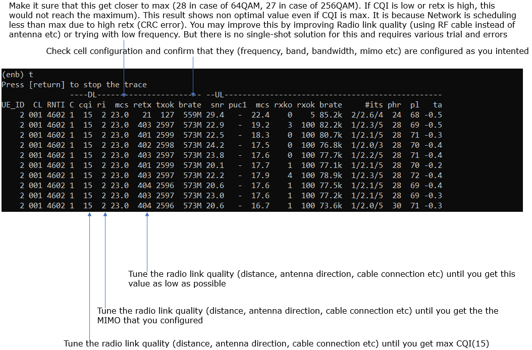
- Monitor and verify throughput using the 't' command. Adjust radio link conditions to optimize throughput.
-
Test 2: LTE FDD b7 BW 20 MHz 2x2 MIMO
- Employ a configuration file modified from enb-b7-20Mhz-2x2.cfg, which is based on gnb-sa.cfg.
- Confirm cell configuration parameters as in Test 1.
- Power on the UE, attach to the cell, and check the assigned IP address.
- Run ./ltesim_server from /root/mme.
- Generate and measure IP throughput.
- Verify throughput with the 't' command and make necessary adjustments to radio link conditions.
-
Test 3: NR SA TDD n78 BW 20 MHz 2x2 MIMO
- Use the default NR SA configuration (gnb-sa.cfg).
- Check all cell configuration settings (frequency, band, bandwidth, MIMO).
- Power on the UE, confirm cell attachment, and verify IP assignment.
- Execute ./ltesim_server from /root/mme.
- Generate IP throughput and monitor the results.
- Use the 't' command to verify throughput. Adjust radio link as needed for optimal performance.
-
Test 4: NR SA TDD n78 BW 50 MHz 2x2 MIMO
- Use the gnb-sa-50Mhz.cfg file, which is a modified version of gnb-sa.cfg.
- Perform the same configuration verification as previous tests.
- Power on the UE, attach to the cell, and check IP assignment.
- Start ./ltesim_server in /root/mme.
- Generate and verify IP throughput.
- Validate throughput using the 't' command and adjust radio link conditions as needed.
-
Test 5: NR SA TDD n78 BW 100 MHz 2x2 MIMO, 2 x sdr50
- Apply the configuration file gnb-sa-2sdr-0-1.cfg, modified from gnb-sa.cfg.
- Verify all cell configuration settings.
- Power up the UE, ensure attachment to the cell, and check IP assignment.
- Run ./ltesim_server from /root/mme.
- Generate IP throughput and monitor performance.
- Use the 't' command to monitor throughput and adjust radio link conditions accordingly for optimal results.
General Methodology:
- For each test, begin with the correct configuration file (default or modified as indicated).
- Verify cell parameters are set as intended for the specific test case.
- Bring up the UE, attach it to the cell, and confirm network connectivity by verifying the assigned IP.
- Start the required server process to facilitate throughput testing.
- Initiate and monitor IP throughput generation, using built-in tools (such as the 't' command) to observe and validate performance metrics.
- Adjust radio link conditions as needed to achieve and verify optimal throughput.
Test Setup
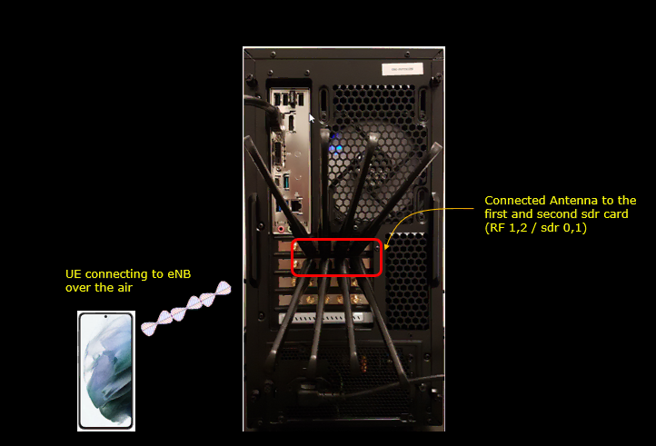
Test setup for this tutorial is as shown below.
- Since this test is for Out of the box testing, I used the default configuration(cfg) file without changing anything in it
- SIM Card used in this tutorial is the one delivered with the system as it is.
- If you want to change the configuration, The tutorial Configuration Guide would help
Test 1 : LTE FDD b7 BW 5 Mhz 2x2 MIMO
In this test, I used default LTE configuration as shown below.

Following is the configuration in enb.default.cfg

Check cell configuration and confirm that they (frequency, band, bandwidth, mimo etc) are configured as you intented

Power on UE and Get UE attached to the cell and check the IP assigned to UE

Go to the directory /root/mme and run ./ltesim_server

Generate IP throughput

Verify the throughput with 't' command and tweak radio link condition to achieve the throughput as much as possible.
Test 2 : LTE FDD b7 BW 20 Mhz 2x2 MIMO
In this test, I used a configuration file that are modified from enb-b7-20Mhz-2x2.cfg which was copied from gnb-sa.cfg as shown below.

Following is the configuration in enb-b7-20Mhz-2x2.cfg

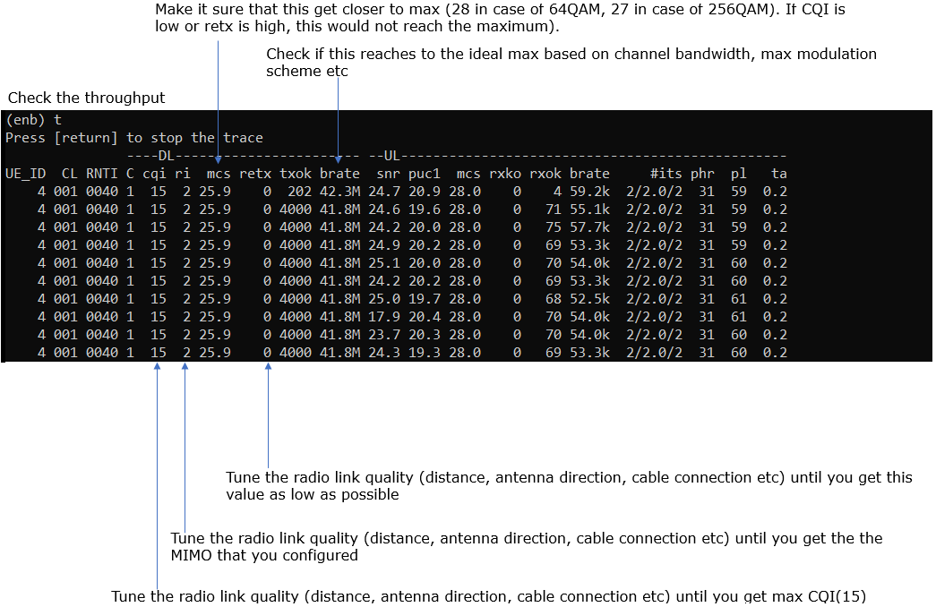
Check cell configuration and confirm that they (frequency, band, bandwidth, mimo etc) are configured as you intented

Power on UE and Get UE attached to the cell and check the IP assigned to UE

Go to the directory /root/mme and run ./ltesim_server

Generate IP throughput

Verify the throughput with 't' command and tweak radio link condition to achieve the throughput as much as possible.
Test 3 : NR SA TDD n78 BW20 Mhz 2x2 MIMO
In this test, I used default NR SA configuration (gnb-sa.cfg) as shown below.

Following is the configuration in gnb-sa.cfg

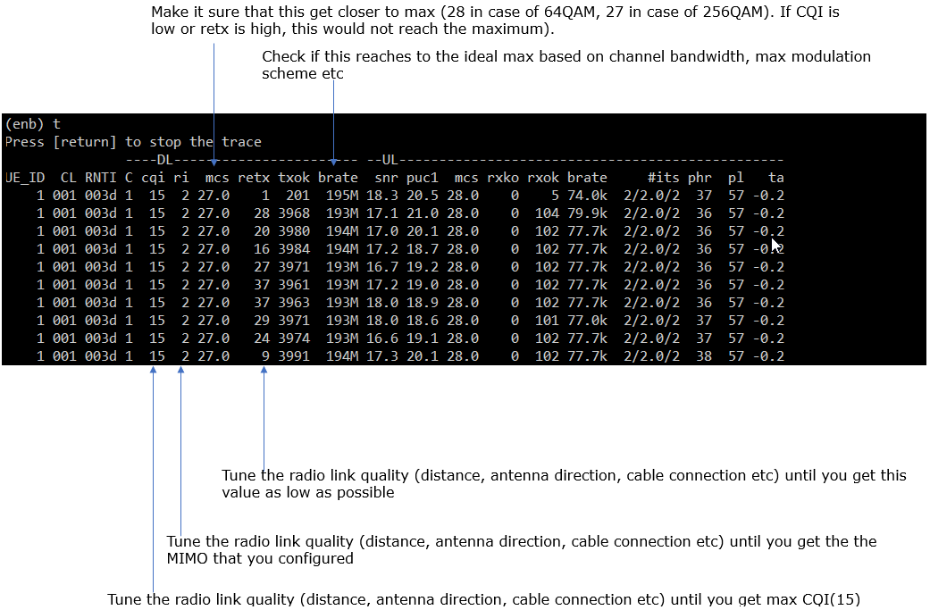
Check cell configuration and confirm that they (frequency, band, bandwidth, mimo etc) are configured as you intented

Power on UE and Get UE attached to the cell and check the IP assigned to UE

Go to the directory /root/mme and run ./ltesim_server

Generate IP throughput

Verify the throughput with 't' command and tweak radio link condition to achieve the throughput as much as possible.
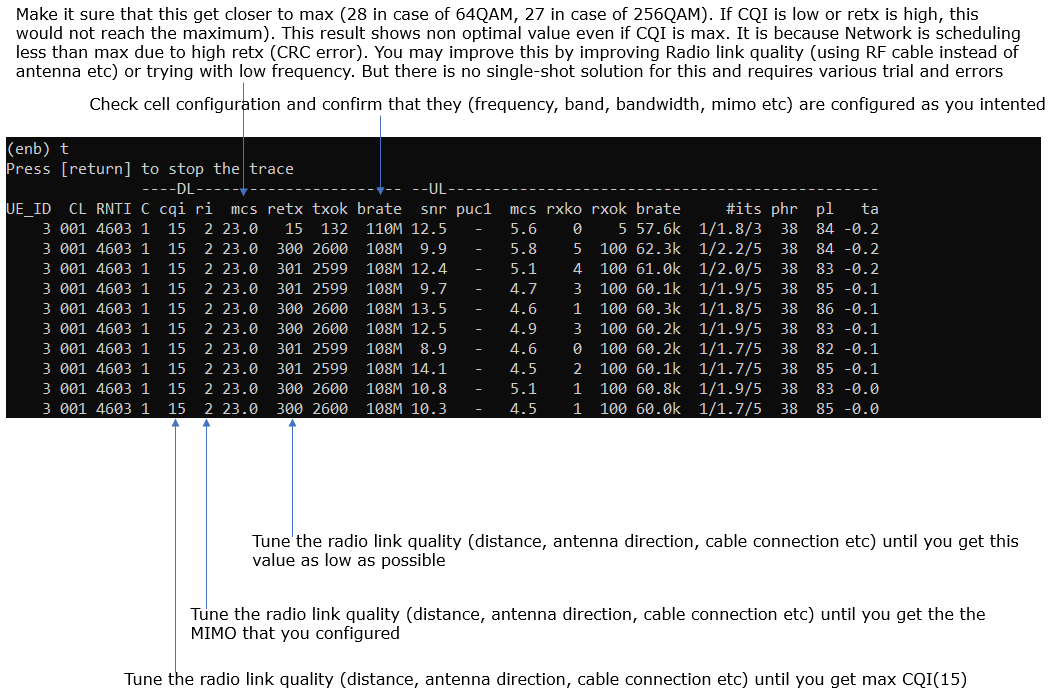
Test 4 : NR SA TDD n78 BW50 Mhz 2x2 MIMO
In this test, I used gnb-sa-50Mhz.cfg which is copied and modified from gnb-sa.cfg as shown below.

Following is the configuration in gnb-sa-50Mhz.cfg

Check cell configuration and confirm that they (frequency, band, bandwidth, mimo etc) are configured as you intented

Power on UE and Get UE attached to the cell and check the IP assigned to UE

Go to the directory /root/mme and run ./ltesim_server

Generate IP throughput

Verify the throughput with 't' command and tweak radio link condition to achieve the throughput as much as possible.
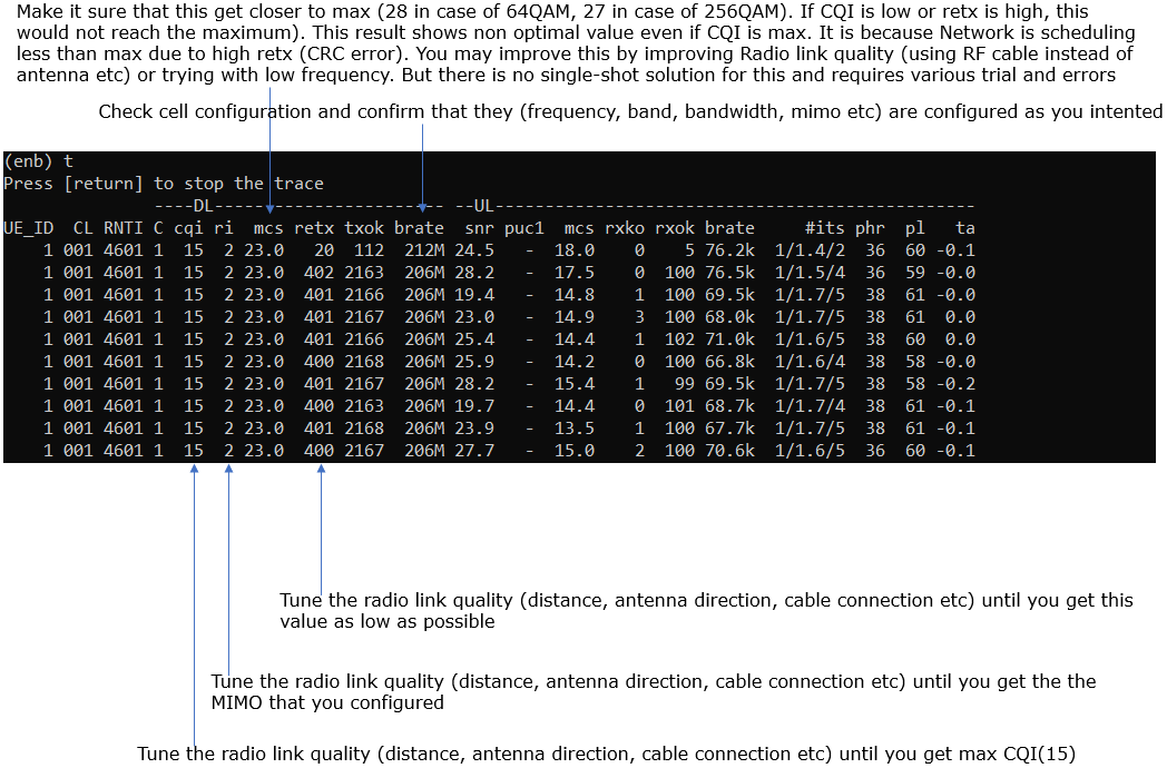
Test 5 : NR SA TDD n78 BW100 Mhz 2x2 MIMO, 2 x sdr50
In this test, I used the configuration gnb-sa-2sdr-0-1.cfg which was copied and modified from gnb-sa.cfg as shown below.

Following is the configuration in gnb-sa-2sdr-0-1.cfg

Check cell configuration and confirm that they (frequency, band, bandwidth, mimo etc) are configured as you intented

Power on UE and Get UE attached to the cell and check the IP assigned to UE

Go to the directory /root/mme and run ./ltesim_server

Generate IP throughput

Verify the throughput with 't' command and tweak radio link condition to achieve the throughput as much as possible.
