LTE Dual SIM
The purpose of this tutorial is to show you how to configure and perform Dual SIM test with LTE network.
DualSIM technology allows a mobile device to support two SIM cards simultaneously. This means the device can manage two different mobile network services at the same time, without the need for carrying two separate phones.
There are mainly two types - DualSIM Standby (DSDS) and DualSIM Dual Active (DSDA).
- DualSIM Standby (DSDS): In this mode, while one SIM card is active for calls or data use, the other becomes inactive.
- DualSIM Dual Active (DSDA): Both SIMs can be active at the same time. This means you can receive calls on one SIM while talking on the other.
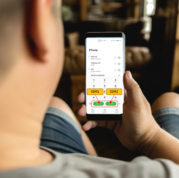
Table of Contents
Introduction
Dual SIM technology in LTE-enabled mobile devices represents a significant advancement in modern telecommunications, allowing a single device to manage two separate mobile network subscriptions concurrently. This capability leverages sophisticated radio and protocol architectures to enable seamless switching or simultaneous operation across different network operators, subscription profiles, or radio access technologies. Dual SIM functionality is categorized primarily into Dual SIM Dual Standby (DSDS) and Dual SIM Dual Active (DSDA) architectures. In DSDS, both SIM cards share the device’s transceiver resources and can remain in standby mode, but only one SIM can be actively engaged in a call or data session at any given moment; once one SIM becomes active, the other is temporarily suspended. DSDA, on the other hand, provides dedicated transceiver resources for each SIM, enabling both SIMs to maintain simultaneous active connections for voice and data, offering users the flexibility to handle calls or data sessions on both subscriptions independently. The integration of Dual SIM support in LTE networks requires coordination at the hardware, firmware, and software levels, including the management of SIM profiles, radio resource allocation, and protocol stack handling to ensure optimal performance and user experience. This technology is particularly valuable for users who wish to separate personal and business communications, frequent travelers managing local and international numbers, or anyone seeking network redundancy. Within the broader mobile ecosystem, Dual SIM capabilities enhance device utility, operator service offerings, and overall user flexibility, making them an essential feature in contemporary smartphones and IoT devices. Understanding how to configure and test Dual SIM functionalities in the context of LTE networks is crucial for engineers, testers, and network operators aiming to deliver robust and reliable multi-SIM experiences.
-
Context and Background
- Dual SIM technology enables one device to manage two SIM cards, supporting multiple network operators or subscription profiles.
- LTE networks require specialized handling of dual SIM operations, including radio resource management and protocol stack coordination.
- Two main architectures exist: DSDS (Dual SIM Dual Standby) and DSDA (Dual SIM Dual Active), each with distinct operational characteristics and hardware requirements.
-
Relevance and Importance
- Dual SIM support increases device flexibility, allowing users to separate business and personal communications or use local and international SIMs without multiple devices.
- Operators and manufacturers leverage Dual SIM to enhance service offerings and address diverse user scenarios.
- Testing and correct configuration are essential to ensure network reliability, seamless switching, and user satisfaction.
-
Tutorial Objectives
- Guide learners through the process of configuring and testing Dual SIM functionality on LTE networks.
- Explain concepts, architectural differences, and practical considerations for DSDS and DSDA modes.
- Provide a structured approach to verifying Dual SIM operations in both laboratory and real-world environments.
-
Learning Outcomes
- Understand Dual SIM architectures and how they are implemented in LTE-enabled devices.
- Gain practical experience in configuring devices for Dual SIM operation and conducting relevant tests.
- Identify and troubleshoot common issues related to Dual SIM usage on LTE networks.
- Develop a strong foundation for further work in device validation, network optimization, or feature development involving multi-SIM scenarios.
-
Prerequisite Knowledge
- Familiarity with basic LTE network architecture and mobile device operation.
- Understanding of SIM card functionality and mobile subscription management.
- Basic experience with device configuration tools and logging or testing environments is recommended.
Summary of the Tutorial
This tutorial demonstrates test procedures for verifying DSDS (Dual SIM, Dual Standby) UE behavior in various VoLTE and data scenarios using Amarisoft callbox. The tutorial comprises three main tests: MT Voice Call, MO Voice Call, and Data Traffic During Voice Call. Each test is outlined below with the focus on test steps, configurations, and methodologies.
-
Test 1 - DSDS MT Voice Call
-
Configuration:
- The necessary configuration files are listed, covering gNB, IMS, MME, UE DB, and OTS components for DSDS operation. Refer to the referenced tutorial for details on applying these files.
-
Test Procedure:
- Verify that the UE has two SIMs configured and enabled.
- Start the callbox and power on the UE (disable Airplane mode).
- Allow the UE to complete the initial attach process for both SIMs.
- On the first IMS server, verify that one USIM is registered (e.g., IMSI 001010123456789).
- On the second IMS server, verify that the other USIM is registered (e.g., IMSI 001010123456780).
- Initiate an MT (Mobile Terminated) call from the first IMS server to the first USIM and confirm the call is received by the corresponding SIM.
- Repeat the MT call from the second IMS server to the second USIM and verify the call is received by the second SIM.
-
Log Analysis:
- Check that both serving cells broadcast the correct PLMN IDs via SIB1.
- Verify each SIM camps on to the correct cell and completes IMS registration.
- Validate the IMS/SIP signaling sequence for VoLTE call setup for both MT call scenarios.
-
Configuration:
-
Test 2 - DSDS MO Voice Call
-
Configuration:
- Use the same configuration files as Test 1.
-
Test Procedure:
- Set up USIMs and complete initial attach as in Test 1.
- Once both USIMs are attached, place an MO (Mobile Originated) voice call from one SIM (e.g., SIM1) to a loopback number configured in the system (e.g., 666).
- Verify that the call is successfully established.
-
Log Analysis:
- Ensure both SIM1 and SIM2 complete IMS registration.
- Check signaling and RTP traffic for the VoLTE MO call from the originating SIM.
-
Configuration:
-
Test 3 - Data Traffic during Voice Call
-
Configuration:
- Same configuration files as in Test 1 are used.
-
Test Procedure:
- Configure USIMs and complete initial attach as previously described.
- Place a voice call from one SIM (e.g., SIM1) to the loopback number.
- While the voice call is ongoing, generate IP data traffic using the other SIM.
- Observe the data traffic behavior during the call; with the tested commercial UE, data traffic was paused during the voice call and resumed after the call ended.
- Perform a ping test to confirm similar behavior (paused packet traffic during voice call).
-
Configuration:
Each test includes steps for initial setup, registration verification, call establishment, and log analysis to ensure correct DSDS operation in VoLTE and data scenarios.
Test Setup
In this tutorial, you may use two types of as shown below. All the components will launch automatically by lte service and all the components will be automatically added to 'screen' window as well.

Test 1 - DSDS MT Voice Call
In this test, I will show you how to make a MT voice call (VoLTE) to each of SIM on DSDS(Dual Sim, Dual Standby) UE.
Configuration
Regarding the details of the configuration (i.e, how to apply each of the configuration file to each of the network component or key parameters in each configuration file), refer to this tutorial. In this tutorial, I would only provide the list of the configuration files.
- gnb-sa-2-plmn_DualSim_DSDS.cfg
- ims.default-0_DualSim_DSDS.cfg
- ims.default-1_DualSim_DSDS.cfg
- mme-ims-0_DualSim_DSDS.cfg
- mme-ims-1_DualSim_DSDS.cfg
- ue_db-ims-dsds-0_DualSim_DSDS.cfg
- ue_db-ims-dsds-1_DualSim_DSDS.cfg
- ots-multi-mme_DualSim_DSDS.cfg
Perform the test
First, check the UE and make sure that two SIMs are configured and enabled. In this example, the UE shows two USIM entries in the SIM management menu. SIM 1 and SIM 2 are both available, and both support 2G/3G/4G/5G. This confirms that the UE recognizes two SIM profiles before starting the Amarisoft test.
Also check the default SIM selection. In this screen, default mobile data is set to SIM 2, and default calling SIM is also set to SIM 2. This means the UE will normally use SIM 2 for data connection and voice call origination unless the user or the UE behavior changes it during the test. This setting is important because the registration, PDU session, paging, and call behavior can be different depending on which SIM is selected as the default service SIM.
At this point, the basic UE-side preparation is complete. Two USIMs are configured on the UE, and SIM 2 is selected as the default SIM for mobile data and calling.

Then start the callbox and power on (Airplane mode off) the UE. (
After the UE is powered on, wait until the initial attach procedure is complete. For a UE supporting Dual SIM, both USIMs are expected to perform the initial attach procedure, so you should wait until the attach procedure is completed for both SIMs before checking the service status.
After the initial attach is complete, check the registered UE status on the first IMS server. In this example, the IMS users command shows that the USIM with IMSI 001010123456789 is registered. The IMPU is shown as sip:001010123456789, and the SIP binding is created with the UE IP address and SIP port. The Options field shows sms, video, and volte, which means the IMS registration includes SMS, video, and VoLTE capability. The IPSec information also confirms that the IMS security association has been established between the UE and the IMS server.
This confirms that one of the two SIMs has completed IMS registration successfully. In this test, IMSI 001010123456789 is registered on the first IMS server.

Check the registered UE status on the second IMS server and make sure that the other USIM is also registered.
In this example, the IMS users command on IMS1 shows that the USIM with IMSI 001010123456780 is registered.
The IMPI is shown as [001010123456780@ims.mnc001.mcc001.3gppnetwork.org](mailto:001010123456780@ims.mnc001.mcc001.3gppnetwork.org), and the IMPU includes sip:001010123456780, tel:0600000001, and tel:601. This means the second SIM has completed IMS registration and has its own SIP identity and telephone number mapping. The SIP binding shows the UE IPv6 address using the 2001:468:1300:1 network and SIP port 31935. This is different from the first IMS server case, so it confirms that the second USIM is using a separate IMS registration path.
The Options field shows sms, video, and volte, which means the second USIM is also registered with SMS, video, and VoLTE capability. The IPSec section shows the authentication and ciphering algorithms, local and remote ports, SPI values, and IMS source/destination addresses. This confirms that IMS security association is established for the second SIM as well.
At this point, both SIMs have completed IMS registration. The first USIM is registered on the first IMS server, and the second USIM with IMSI 001010123456780 is registered on the second IMS server.

Then make an MT call from the first IMS server to the USIM with IMSI 001010123456789. Before making the call, check the IMS users status again and confirm that this USIM is still registered on the first IMS server. In this example, the registered user is 001010123456789, and the IMPU includes tel:0600000000 and tel:600. This means the first SIM is reachable through this IMS server for an incoming call.
The command mt_call 001010123456789 is used to trigger a mobile terminated IMS call toward this USIM. Since this is an MT call, the call is originated from the IMS server side and delivered to the UE through the IMS registration associated with SIM 1. This step verifies that the first SIM can receive an incoming VoLTE call while both SIMs are registered in the Dual SIM test setup.

Then you should see the incoming call on the UE side. In this example, the call is delivered to USIM 1, which is the USIM registered on the first IMS server.
The incoming call screen shows Unknown as the caller because the call is generated from the IMS server test command, not from a normal contact entry. The SIM indicator on the call screen shows USIM, and the highlighted test note indicates Call for USIM 1. This confirms that the MT call triggered from the first IMS server is routed to the first SIM.
This step verifies that USIM 1 can receive an incoming VoLTE call while both SIMs are enabled and registered.

Now make an MT call from the second IMS server to the USIM with IMSI 001010123456780. Before triggering the call, check the IMS users status on IMS1 and confirm that the second USIM is still registered. In this example, the registered user is 001010123456780, and the IMPU includes tel:0600000001 and tel:601. This means the second SIM is reachable through the second IMS server.
The command mt_call 001010123456780 is used to generate a mobile terminated IMS call toward the second USIM. Since this command is executed from the second IMS server, the call should be routed through the IMS registration associated with USIM 2. This step verifies that the second SIM can also receive an incoming VoLTE call independently from the first SIM in the Dual SIM setup.

Then you should see the incoming call on the UE side. In this example, the call is delivered to USIM 2, which is the USIM registered on the second IMS server.
The incoming call screen shows Unknown as the caller, and the SIM indicator shows 2 USIM. The test label also shows Call for USIM 2. This confirms that the MT call triggered from the second IMS server is routed to the second SIM, not to the first SIM.
This step verifies that both SIMs can receive MT VoLTE calls separately. The first IMS server can reach USIM 1, and the second IMS server can reach USIM 2. This confirms the basic Dual SIM IMS registration and MT call routing behavior in the Amarisoft test setup.

Log Analysis
First, confirm that SIB1 of Cell 1 is broadcast as intended. In this test, the WebGUI log shows repeated SIB1 messages on BCCH-DL-SCH for Cell 1. When one of the SIB1 messages is selected, the decoded message on the right side shows systemInformationBlockType1 and cellAccessRelatedInfo. In plmn-IdentityList, the MCC is set to 001 and the MNC is set to 01. This means Cell 1 is broadcasting PLMN 001-01 as configured.
This is an important first checkpoint in the Dual SIM test. Before checking UE attach or IMS registration, you should confirm that each cell is broadcasting the expected PLMN. If the PLMN in SIB1 is wrong, the UE may not select the intended cell, or the SIM may not try to register on the expected network. In this example, Cell 1 is correctly configured with PLMN 001-01, so the first SIM can treat this cell as a valid serving cell for registration.

Then, confirm that SIB1 of Cell 2 is also broadcast as intended. In this test, the WebGUI log shows repeated SIB1 messages on BCCH-DL-SCH for Cell 2. When the SIB1 message for Cell 2 is selected, the decoded message shows systemInformationBlockType1 and cellAccessRelatedInfo. In plmn-IdentityList, the MCC is set to 460 and the MNC is set to 02. This means Cell 2 is broadcasting PLMN 460-02 as configured.
This is the second important checkpoint in the Dual SIM test. Since the two SIMs are expected to attach to different networks, each cell should broadcast the PLMN that matches the intended USIM. Cell 1 broadcasts PLMN 001-01, and Cell 2 broadcasts PLMN 460-02. Therefore, the UE can recognize both cells as separate serving network candidates and each USIM can perform registration toward its matching PLMN.

When power ON the UE that supports DUAL SIM, one of the SIM camp on to one of the cell. In this case, one UE camps onto the cell with PLMN 460-02 (Cell 2).
When the Dual SIM UE is powered on, one of the SIMs first camps on one of the cells. In this example, the log shows that the USIM with IMSI 001010123456780 starts the RRC connection procedure on Cell 2. Since Cell 2 broadcasts PLMN 460-02, this means the SIM associated with PLMN 460-02 is camping on Cell 2 as expected.
The message flow starts with RRC setup request, followed by RRC setup and RRC setup complete. After that, several DL information transfer and UL information transfer messages are exchanged. These messages usually carry NAS signaling between the UE and the core network, such as registration and authentication-related procedures. The log also shows security mode command and security mode complete, which means AS security is activated for this RRC connection.
After security activation, the network sends UE capability enquiry and the UE responds with UE capability information. Then RRC reconfiguration and RRC reconfiguration complete are exchanged. This means the network configures the UE with the required radio bearer and radio resource settings. In this test, these messages confirm that the SIM for PLMN 460-02 successfully camps on Cell 2 and proceeds through the normal RRC and NAS setup procedure.

Then the other SIM camp on to the other cell. In this case, the other UE camps onto the cell with PLMN 001-01(Cell 1).
In this example, the log shows that the USIM with IMSI 001010123456789 starts the RRC connection procedure on Cell 1. Since Cell 1 broadcasts PLMN 001-01, this means the SIM associated with PLMN 001-01 is camping on Cell 1 as expected.
The flow starts with RRC connection request, followed by RRC connection setup and RRC connection setup complete. After this, DL information transfer and UL information transfer messages are exchanged. These messages normally carry NAS procedures such as registration, authentication, security, and session-related signaling between the UE and the core network.
The log also shows security mode command and security mode complete. This confirms that AS security is activated for this SIM on Cell 1. Then the network sends UE capability enquiry, and the UE responds with UE capability information. After that, RRC connection reconfiguration and RRC connection reconfiguration complete are exchanged, which means the radio bearer and related radio configuration are applied.
At this point, both SIMs have selected their intended cells. The SIM for PLMN 460-02 camps on Cell 2, and the other SIM for PLMN 001-01 camps on Cell 1. This confirms the basic Dual SIM cell selection and registration behavior in this Amarisoft setup.

Once the initial registration is complete, one of the USIMs starts IMS registration. In this example, the log shows SIP REGISTER from the UE toward the IMS server. The REGISTER message is sent using the IMS identity of 001010123456780, and the destination is the IMS domain ims.mnc001.mcc001.3gppnetwork.org.
At first, the IMS server responds with 401 Unauthorized. This is expected in IMS registration. It does not mean registration failure. It means the IMS server is challenging the UE to perform authentication. After that, the UE sends another REGISTER message with authentication information. The IMS server then accepts the registration and returns 200 OK.
The log also shows related IMS procedures after registration, such as SUBSCRIBE and NOTIFY. These messages are part of IMS service status handling after successful registration. At this point, one of the two SIMs has completed IMS registration successfully, so this SIM can be used for IMS services such as VoLTE, SMS over IMS, and incoming call testing.

Then the remaining USIM completes IMS registration as well. In this example, the log shows SIP REGISTER for IMSI 001010123456789 after the first SIM has already completed its IMS registration.
The registration flow is the normal IMS registration sequence. The UE first sends REGISTER to the IMS server. The IMS server responds with 401 Unauthorized, which is the expected IMS authentication challenge. Then the UE sends another REGISTER with the authentication response, and the IMS server returns 200 OK. This confirms that the IMS registration is accepted.
After successful registration, the log also shows the following IMS service procedures such as SUBSCRIBE and NOTIFY. These messages indicate that the UE is subscribing to IMS service status and receiving the corresponding notification from the IMS server.
At this point, both USIMs have completed IMS registration. One USIM is registered through one IMS path, and the remaining USIM is registered through the other IMS path. This confirms that the Dual SIM UE can maintain IMS registration for both SIMs in this Amarisoft setup.

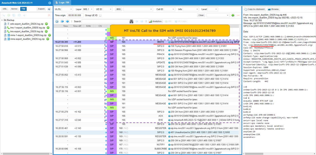
When you make an MT call to 001010123456789, you can see the IMS/SIP sequence for VoLTE call setup in the log. In this example, the call is delivered to the SIM with IMSI 001010123456789, which is already registered to IMS.
The call setup starts with SIP INVITE from the IMS server toward sip:001010123456789. This INVITE is the main call setup message for the MT VoLTE call. The message includes SDP information, so it also carries the media negotiation information such as codec and RTP parameters. After the INVITE, the UE responds with 100 Trying, which means the UE side has received the call request and started processing it.
Then the log shows 183 Session Progress and PRACK. This is used for early media and reliable provisional response handling. After that, UPDATE and 200 OK are exchanged, which means the SIP session parameters are being confirmed before the call is fully answered. The 180 Ringing message indicates that the UE is now alerting the user, so this corresponds to the ringing screen shown on the phone.
After the user accepts the call, the log shows 200 OK for the INVITE and then ACK. This completes the SIP call setup. At this point, the VoLTE call is established for the SIM with IMSI 001010123456789. Later, BYE is shown when the call is released, followed by 200 OK for the BYE. This confirms that the MT VoLTE call setup and release are completed normally for the first SIM.
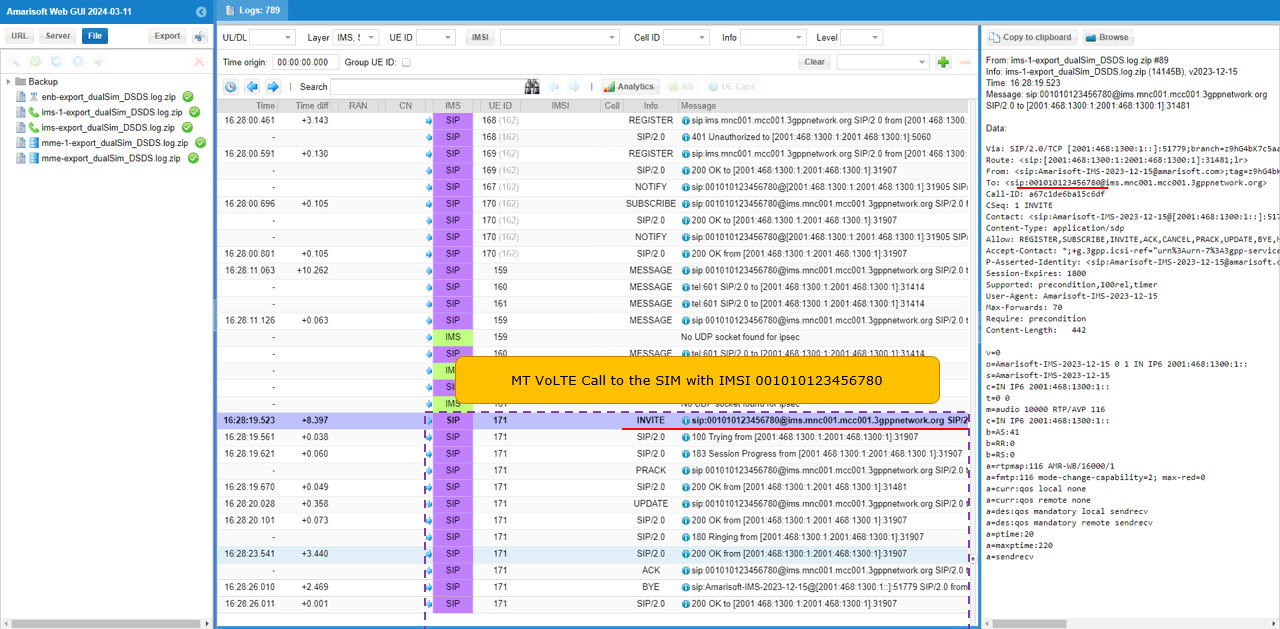
When you make an MT call to 001010123456780, you can see the IMS/SIP sequence for VoLTE call setup in the log. In this example, the call is delivered to the SIM with IMSI 001010123456780, which is registered through the second IMS path.
The call setup starts with SIP INVITE toward sip:001010123456780. This INVITE is the MT VoLTE call setup message, and the decoded message on the right shows the SIP header and SDP information. The SDP part includes the media information such as RTP port, codec, and AMR-WB related parameters.
After the INVITE, the UE responds with 100 Trying, which means the UE has received the incoming call request. Then 183 Session Progress and PRACK are exchanged, followed by 200 OK. This is the normal reliable provisional response handling during VoLTE call setup. The UPDATE and 200 OK messages are then exchanged to confirm the session parameters before the call is fully connected.
The 180 Ringing message indicates that the UE is alerting the user for the incoming call on this SIM. When the call is answered, the UE sends 200 OK for the INVITE, and the IMS server responds with ACK. This completes the SIP call setup. After that, BYE and 200 OK are shown when the call is released.
This confirms that the MT VoLTE call to IMSI 001010123456780 is successfully routed to the second SIM and that the SIP call setup and release procedure are completed normally.
Test 2 - DSDS MO Voice Call
In this test, I will show you how to make a MO voice call (VoLTE) from one of SIM on DSDS(Dual Sim, Dual Standby) UE.
Configuration
The configuration for this test is same as the configuration in previous test (Test 1).
Perform the test
USIM settings and initial attach process for this test is same as the operations in previous test(Test 1). It is assumed that you get both USIM successfully attached.
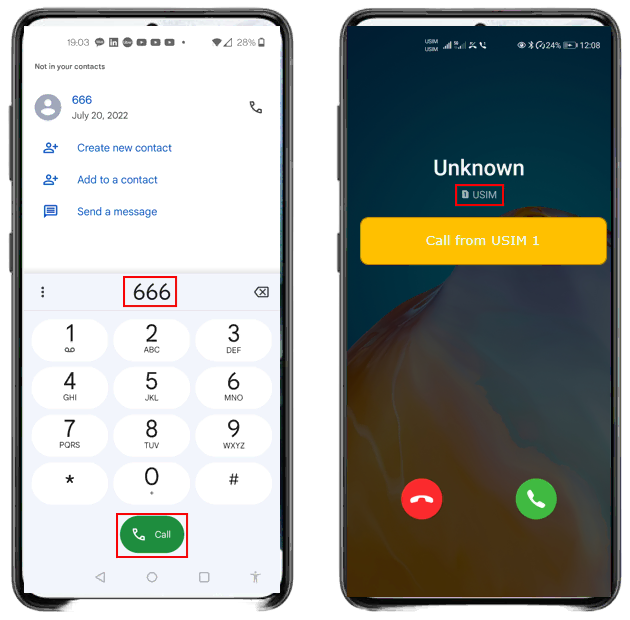
Once the initial attachment is complete, make a call from one of the USIMs. In this example, the call is made from SIM 1 to the loopback number configured in the Amarisoft configuration file. The loopback number used in this test is 666.
On the UE, enter 666 in the dialer and press the Call button. Since the call is made from SIM 1, the call screen shows Call from USIM 1. This confirms that the MO VoLTE call is originated from the first SIM.
After placing the call, make sure that the call goes through successfully. This step verifies that SIM 1 can originate a VoLTE call through its IMS registration, and that the Amarisoft loopback call service is working for the selected SIM.
Log Analysis
Assuming that the initial attachment is complete, the first thing to check is whether SIM 1 completes IMS registration successfully. In this example, the log shows the SIP REGISTER procedure for IMSI 001010123456780.
The first REGISTER is sent from the UE to the IMS server. The IMS server responds with 401 Unauthorized. This is the normal IMS authentication challenge, so it does not indicate a failure. After receiving this challenge, the UE sends another REGISTER with authentication information. Then the IMS server accepts the registration and returns 200 OK.
After the registration is accepted, the log shows the IMS binding update and service-related SIP messages such as SUBSCRIBE and NOTIFY. This means SIM 1 has completed IMS registration and is ready for IMS services such as VoLTE.
This is the first checkpoint before analyzing the MO call itself. If SIM 1 does not complete IMS registration, the UE cannot originate a VoLTE call from this SIM. In this test, SIM 1 completes IMS registration successfully, so the next step is to check the SIP INVITE generated when the call to 666 is made.

Ensure that SIM 2 also completes IMS registration. In this example, the log shows the SIP REGISTER procedure for IMSI 001010123456789.
The UE first sends REGISTER to the IMS server. The IMS server responds with 401 Unauthorized, which is the expected IMS authentication challenge. Then the UE sends another REGISTER with the authentication response, and the IMS server returns 200 OK. This confirms that SIM 2 has completed IMS registration successfully.
After registration, the log also shows SUBSCRIBE and NOTIFY messages. These are service-related IMS messages after registration. This means SIM 2 is also ready for IMS service.
This checkpoint is important before checking the MO voice call. In DSDS testing, both SIMs should be attached and IMS registered first. Then, when the user makes a call from one selected SIM, the SIP INVITE should appear under the IMS registration path of that SIM. In this example, SIM 2 registration is complete, and the following SIP INVITE to tel:666 can be checked as the MO VoLTE call setup.

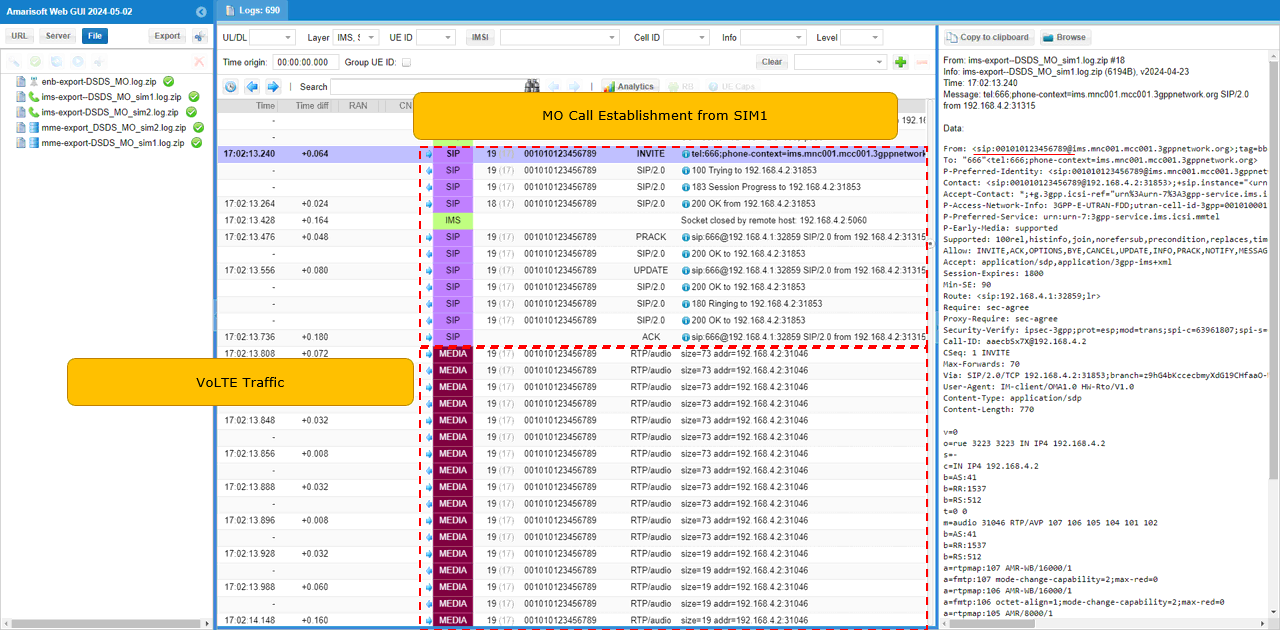
When you make an MO voice call from one of the SIMs, SIM 1 in this example, you can see both VoLTE call setup signaling and RTP traffic in the log.
The call setup starts with SIP INVITE from IMSI 001010123456789 toward tel:666. This confirms that the call is originated from the selected SIM and that the dialed number is the configured loopback number. After the INVITE, the log shows the normal VoLTE SIP sequence, including 100 Trying, 183 Session Progress, PRACK, UPDATE, 180 Ringing, 200 OK, and ACK. This means the SIP session is successfully established for the MO VoLTE call.
After the SIP call setup is completed, the log shows MEDIA RTP/audio packets. These RTP/audio entries indicate that voice media traffic is flowing for the established VoLTE call. In this example, the RTP packets are associated with the same UE/IMSI context, so it confirms that the call from SIM 1 is not only signaled successfully but also has active media traffic.
This verifies the MO VoLTE call from SIM 1. The selected SIM sends the SIP INVITE to the loopback number 666, the IMS server completes the SIP call setup, and RTP/audio traffic starts after the call is connected.
Test 3 - Data Traffic during Voice Call
In this test, I will show you how to make a MO voice call (VoLTE) from one of SIM on DSDS(Dual Sim, Dual Standby) UE.
Configuration
The configuration for this test is same as the configuration in previous test (Test 1).
Perform the test
USIM settings and initial attach process for this test is same as the operations in previous test(Test 1). It is assumed that you get both USIM successfully attached.
Once the initial attachment is complete, make a voice call from one of the USIMs. In this example, the call is made from SIM 1 to the loopback number configured in the Amarisoft configuration file. The loopback number used in this test is 666.
On the UE, enter 666 in the dialer and press the Call button. Since the call is originated from SIM 1, the call screen shows Call from USIM 1. This confirms that the MO VoLTE call is started from the first SIM.
After the call is connected, keep the call active and then generate data traffic from the UE. This allows you to check whether packet data can continue while the DSDS UE is already using one SIM for VoLTE. In the log analysis, you should verify two things together: the SIP/RTP traffic for the active voice call and the user-plane data traffic during the same call period.
While the voice call is active on one SIM, generate IP data traffic using the other SIM and check whether both traffic types go through at the same time.
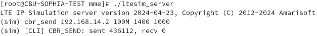
In this example, ltesim_server is started on the MME side, and the cbr_send command is used to generate constant bit rate IP traffic toward 192.168.14.2. The command cbr_send 192.168.14.2 100M 1400 1000 means that the simulator sends IP packets to the UE-side IP address with 100 Mbps target rate, 1400-byte packet size, and 1000 packets.
The result shows CBR_SEND: sent 436112, recv 0. This means the Callbox side generated and sent a large amount of downlink IP traffic toward the UE. This traffic should be checked together with the ongoing VoLTE call traffic in the log. The key point of this test is to confirm that RTP/audio traffic for the active voice call continues on one SIM while IP data traffic is also generated through the other SIM.
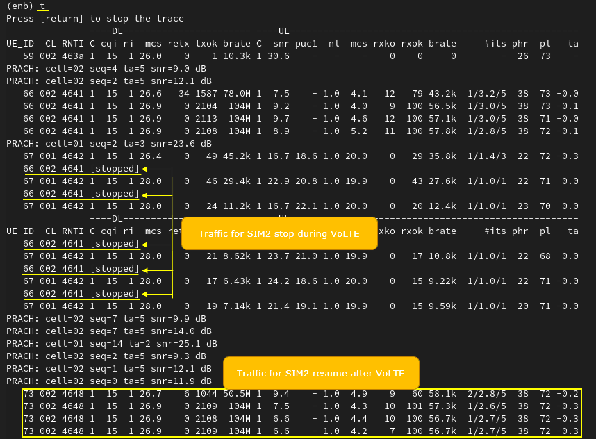
This result is not the expected concurrent data behavior, but it shows the actual behavior of this commercial DSDS UE. While the VoLTE call is active on one SIM, the IP data traffic on the other SIM does not continue continuously. Instead, the traffic for SIM 2 is shown as stopped during the VoLTE call period.
In the trace, SIM 2 traffic is visible before the call, but during the active VoLTE period the corresponding UE entry repeatedly shows stopped. This means the UE is not scheduling normal packet data traffic for that SIM while the other SIM is occupied with the voice call. This behavior is common for many DSDS implementations because the UE may share one RF chain or one active modem path between the two SIMs. Even though both SIMs are registered in standby mode, simultaneous active voice and data on different SIMs may not be supported.
After the VoLTE call is completed, the trace shows that SIM 2 traffic resumes. The lower part of the log shows new throughput values again, such as around 50.5M and 104M on the downlink side. This indicates that the IP data path itself is not broken. It was only suspended during the VoLTE call and resumed after the voice session ended.
So the conclusion from this test is that this UE behaves as DSDS, not as fully simultaneous DSDA. Both SIMs can remain registered and reachable, but when one SIM is in an active VoLTE call, data traffic on the other SIM can be paused depending on UE implementation.
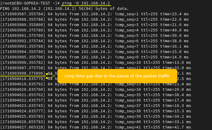
You will have a similar result with a ping test as well. In this example, ping is running toward 192.168.14.2 while the VoLTE call test is performed. Before the VoLTE interruption, ping replies are received regularly with normal ICMP sequence numbers.
During the active VoLTE period, there is a long timestamp gap between two ping replies. This indicates that packet traffic is paused during that time. The ping sequence does not continue with the normal interval while the UE is occupied by the VoLTE call on the other SIM.
After the VoLTE call is completed, ping replies resume again. This matches the result seen with the CBR traffic test. The packet data path is not permanently disconnected, but it is suspended during the active voice call and resumes afterward.
This confirms that, for this commercial DSDS UE, data traffic on one SIM can be paused while the other SIM is in an active VoLTE call. So the behavior is not simultaneous voice-plus-data across two SIMs. It is more like standby support for both SIMs, with only one SIM getting active radio service during the call.