Running Multiple MME
The purpose of this tutorial is to show you how to run multiple MME and let multiple cells get connected to different MME. You can run multiple instances of mme in a callbox without any extra license requirement. The main use case for this is to test roaming scenario.
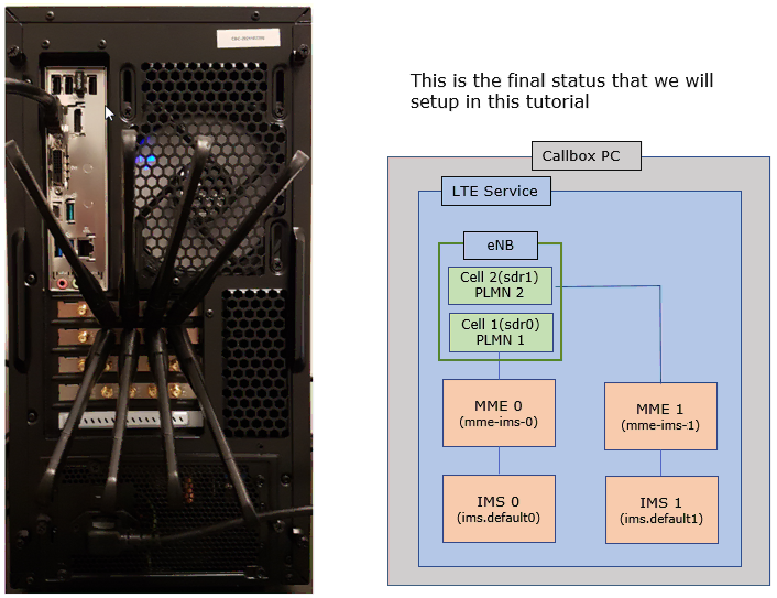
In live network, multiple RAN belongs to different carriers and multiple separate core network are involved in roaming scenario. In Amarisoft callbox, running multiple instances of RAN(eNB, gNB) requires additional license and further tricky setup. As an alternative, it is recommend to use single instance of eNB/gNB with multiple cells that has different PLMN and then run the multiple instances of Core Network (MME) as roaming test environment.
Table of Contents
Introduction
In modern mobile telecommunications, the Evolved Packet Core (EPC) forms the fundamental backbone for LTE networks, coordinating all essential processes such as user authentication, mobility management, and inter-network connectivity. At the heart of the EPC, the Mobility Management Entity (MME) is responsible for managing signaling between the user equipment (UE) and the core network, orchestrating tasks like bearer activation/deactivation, security procedures, and handover decisions. In real-world deployments, especially in roaming scenarios, multiple MMEs are used to represent different core networks belonging to various operators, enabling seamless service continuity and network interoperability as users move across geographical and administrative boundaries. This tutorial focuses on demonstrating how to configure and operate multiple MME instances within a single test environment, specifically using an Amarisoft callbox. By leveraging this approach, engineers can simulate complex roaming scenarios—where different cells (each with unique Public Land Mobile Networks, or PLMNs) connect to distinct MMEs—without the need for additional hardware licenses or intricate RAN setups. This configuration mirrors live network architectures where multiple RANs and core networks coexist, thus providing a powerful and cost-effective platform for development, validation, and troubleshooting of roaming functionalities. Understanding this architecture is vital for network engineers, testers, and solution architects aiming to ensure robust roaming support, optimize inter-operator interactions, and maintain high service reliability within heterogeneous mobile ecosystems.
-
Context of the Technology
- The tutorial centers on LTE/EPC architecture, with an emphasis on the role of the Mobility Management Entity (MME) within the core network.
- In a typical roaming scenario, multiple MMEs are deployed to represent core networks from different operators, supporting inter-PLMN connectivity and user mobility.
- Amarisoft callbox is used as a testbed, offering a flexible environment to emulate live network conditions without extensive hardware requirements.
-
Relevance and Importance
- Roaming functionality is critical for mobile users requiring uninterrupted service across different operator networks.
- Testing roaming in a controlled lab setup allows for early detection of interoperability issues, security vulnerabilities, and handover failures.
- Using multiple MMEs in a single callbox streamlines the simulation of complex scenarios, reduces licensing costs, and accelerates the development/testing lifecycle.
-
Learning Outcomes
- Acquire practical skills to deploy and manage multiple MME instances within a single test environment.
- Gain insights into configuring multiple cells with distinct PLMNs and associating them with separate MMEs.
- Understand the architectural principles behind roaming, core network segmentation, and inter-PLMN signaling flows.
- Learn troubleshooting techniques for common challenges encountered in multi-MME and roaming scenarios.
-
Prerequisite Knowledge and Skills
- Familiarity with LTE/EPC architecture, including components such as eNB/gNB, MME, and PLMN concepts.
- Basic understanding of Amarisoft callbox operation, including instance management and network configuration.
- Experience with Linux-based environments and network virtualization is beneficial for efficient setup and troubleshooting.
Summary of the Tutorial
This tutorial demonstrates the procedure to set up and verify a multi-MME and multi-IMS configuration on a single callbox PC, focusing on configuration steps and test methodology. The test involves launching two instances each of MME and IMS, associating each to different eNB cells and PLMNs, and verifying their operation using the lte service and network/OS tools. The following summarizes the test procedure:
-
Test Setup:
- Two instances of MME and IMS are configured and launched automatically by the lte service on a single callbox PC.
- All components are managed within a 'screen' session for easier monitoring.
- A single or duplicated ue_db configuration may be used, but care should be taken to avoid mismatches.
-
Configuration Procedures:
-
eNB Configuration:
- The eNB configuration file (enb-2cell-2plmn.cfg) is set up with two cells, each mapped to distinct rf_port and PLMN values.
- Each cell is explicitly assigned to a different PLMN (e.g., 00101 and 00102).
- Multiple mme_addr entries are added to associate with both MME instances.
- plmn_list[] in the cell_default section is commented out to allow per-cell PLMN configuration.
-
MME Configuration:
- Two separate MME configuration files (mme-ims-0.cfg and mme-ims-1.cfg) are created, each with distinct GTP addresses and PLMN assignments.
- mme-ims-0.cfg is aligned with the first cell and uses default MME settings for PDN/APN and IMS associations.
- mme-ims-1.cfg is configured for a different PLMN and uses distinct network addresses and IMS associations from MME 0.
- Each MME has its own set of PDN/APN entries and IP address pools configured accordingly.
-
IMS Configuration:
- Two IMS configuration files (ims.default0.cfg and ims.default1.cfg) are created, each aligned to one MME and with different network parameters as required.
- Address and binding parameters (e.g., sip_addr, sctp_addr, etc.) are set per IMS instance to avoid conflicts.
-
OTS Configuration:
- The OTS configuration (ots-multi-mme.cfg) is updated to register both MME and IMS configurations as separate components in the UI.
- MME_CONFIG_FILE, MME1_CONFIG_FILE, IMS_CONFIG_FILE, and IMS1_CONFIG_FILE variables are set to their respective symbolic link paths.
-
eNB Configuration:
-
Test Execution and Verification:
- The lte service is started; all eNB and MME components launch automatically and are available in the screen session.
- The presence of mme1 as a new component in both the screen session and WebGUI is verified.
- Network interfaces (TUN devices) created by each MME configuration are checked using OS tools to confirm correct instantiation.
- IPv4 and IPv6 routing tables are examined to verify routes established by the lte service and OS.
- eNB connection to both MMEs is confirmed by inspecting the S1 setup status using the screen interface.
- Each MME’s connection to the eNB and each IMS’s connection to its associated MME are verified via their respective UIs.
-
Log Analysis:
- Sample logs capture the startup sequence, including SCTP socket establishment, S1 setup requests and responses between eNB and each MME, and SIB1 broadcast from each cell using the configured PLMN.
- The addition of the new MME1 component is confirmed visually in the WebGUI log screenshots.
The tutorial does not perform UE attach procedures but focuses on the infrastructure setup and verification of multi-MME/multi-IMS operation, ensuring each network element is correctly configured and operational.
Test Setup
In this setup, two instances of MME/IMS are running in the callbox. All the components will launch automatically by lte service and all the components will be automatically added to 'screen' window as well. (
Configuration
The configuration for this use case is pretty complicated comparing to regular use case because you need to add additional components (MME1 and IMS1 in this case) and associate separate configuration files for them. In addition, you need to modify OTS configuration as well to incoporate the newly added components.
Configuration File Setup
I used enb-2cell-2plmn.cfg which is copied and modified from enb-2cell-ho.cfg (These configuration files are located in /root/enb/config).

I used two separate mme configuration files : mme-ims-0.cfg and mme-ims-1.cfg which are copied and modified from mme-ims.cfg. Note that mme0.cfg and mme1.cfg are symbolically linked to mme-ims-0.cfg and mme-ims-1.cfg respectively. (These configuration files are located in /root/mme/config).

I used two separate ims configuration files : mme.default.0.cfg and mme.default1.cfg which are copied and modified from ims.default.cfg. Note that ims0.cfg and ims1.cfg are symbolically linked to ims.default0.cfg and ims.default1.cfg respectively. (These configuration files are located in /root/mme/config).

I used ots-multi-mme.cfg which is copied and modiefied from ots.default.cfg (These configuration files are located in /root/ots/config).

Configuration for eNB
In enb-2cell-2plmn.cfg , I made modifications as follows. Note that one more mme_addr is added. 127.0.1.100 is gtp_addr of MME 0 and 127.0.1.101 is gtp_addr of MME 1.

Since all the mmes are running on the same PC as ENB in test setup, you can keep gtp_addr as it is without any change.

Now we are going to two cells with different PLMNs and get each of them mapped to different rf port.
The first cell is mapped to rf_port 0 and PLMN 00101 is set the cell.

The second cell is mapped to rf_port 1 and PLMN 00102 is set the cell.

Comment out plmn_list[] in cell_default. We do this because we want to specify different PLMN for each of the cells. If you specify PLMN in cell_default, that same PLMN applies to every cells which is not intended for this use case.

Configuration for MME 0
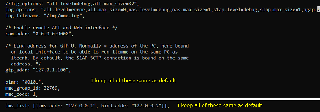
Followings are the configuration in mme-ims-0.cfg. This MME will be associated with the first cell of ENB. We will use the contents of the default mme configuration to MME 0.
Keep gtp_addr, plmn and ims_list same as in the default configuration.
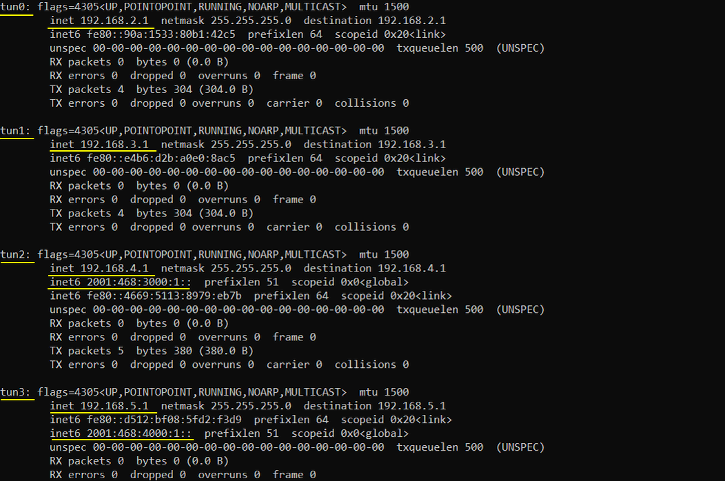
Keep the "default" PDN/APN as in the default configuration file. ptn_type is "ipv4", the range of ip address is 192.168.2.2~192.168.2.254

Keep the "internet" PDN/APN as in the default configuration file. ptn_type is "ipv4" and "ipv4v6", the range of ip address is 192.168.3.2~192.168.3.254 and 2001:468:2000:1::~2001:468:2000:ffff:: respectively.

Keep the "ims" PDN/APN as in the default configuration file. ptn_type is "ipv4v6", the range of ip address is 192.168.4.2~192.168.4.254 and 2001:468:3000:1::~2001:468:3000:ffff:: respectively.

Keep the "ims" PDN/APN as in the default configuration file. ptn_type is "ipv4v6", the range of ip address is 192.168.5.2~192.168.5.254 and 2001:468:4000:1::~2001:468:4000:ffff:: respectively.

Configuration for MME 1
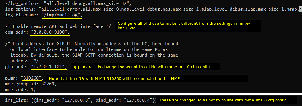
Followings are the configuration in mme-ims-1.cfg. NOTE that this MME has configured for the PLMN 310260 and use the gtp_addr which is different from MME 0. Also mis_addr and bind_addr in ims_list are set differently from MME 0.
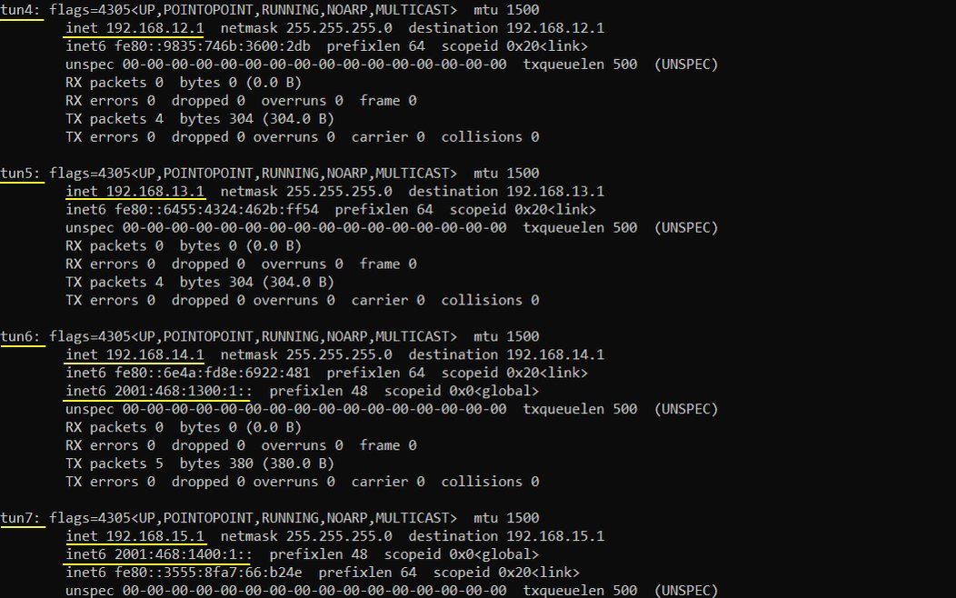
Set "default" PDN/APN differently from MM0 configuration. ptn_type is "ipv4", the range of ip address is 192.168.12.2~192.168.12.254

Set "internet" PDN/APN differently from MM0 configuration. ptn_type is "ipv4" and "ipv4v6", the range of ip address is 192.168.13.2~192.168.13.254 and 2001:468:1200:1::~2001:468:1200:ffff:: respectively.

Set "ims" PDN/APN differently from MM0 configuration. ptn_type is "ipv4v6", the range of ip address is 192.168.14.2~192.168.14.254 and 2001:468:1300:1::~2001:468:1300:ffff:: respectively.

Set "sos" PDN/APN differently from MM0 configuration. ptn_type is "ipv4v6", the range of ip address is 192.168.15.2~192.168.15.254 and 2001:468:1400:1::~2001:468:1400:ffff:: respectively.

Configuration for IMS 0
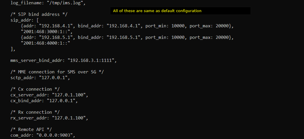
Followings are the configuration in ims.default0.cfg.
The addr and bind_addr of sip_addr and all other parameters (sctp_addr, cx_server_addr, cx_bind_addr, rx_server_addr) are same as in the default ims configuration.
Configuration for IMS 1
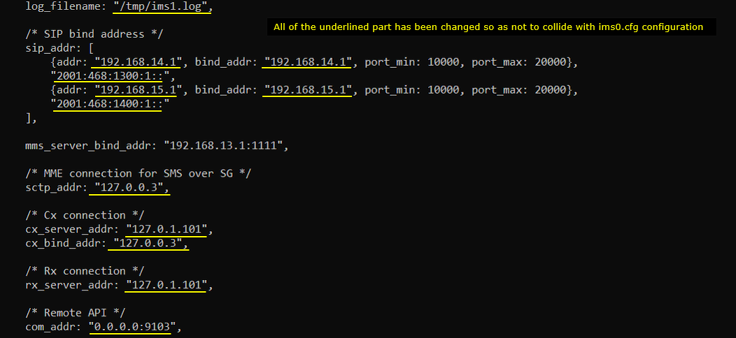
Followings are the configuration in ims.default1.cfg. You should configure the parameters differently from the IMS 0 configuration.
The addr and bind_addr of sip_addr and all other parameters (sctp_addr, cx_server_addr, cx_bind_addr, rx_server_addr) are set differently from the configuration of IMS 0.
Configuration for OTS
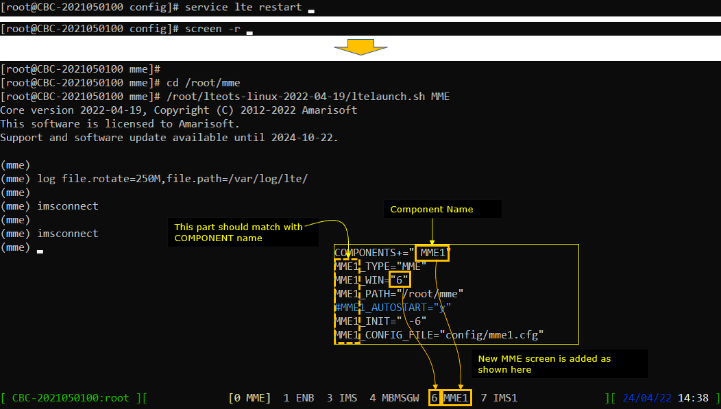
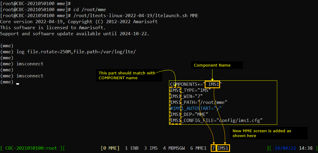
Followings are the configuration in ots-multi-mme.cfg The purpose of this step is to integrate the new components into the screen UI(User Interface).
First set the MME_CONFIG_FILE (the configuration file pointer for the first MME) to "config/mme0.cfg". And then create a new Components named " MME1" and map MME1_CONFIG)FILE to "config/mme1.cfg"

Then set the IMS_CONFIG_FILE (the configuration file pointer for the first IMS) to "config/ims0.cfg". And then create a new Components named " IMS1" and map IMS1_CONFIG)FILE to "config/ims1.cfg"

Perform the test
In this test, I would just run a lte service with additional MME. I would not try any UE attach. In this test, all the eNB and mme is run automtically by lte service.
If you run lte service and get into screen mode, you will see a new component (mme1) is added as below. This addition is done by the configuration in ots.cfg as indicated below.
Now check out the network interface while the service is running and you will see many tun interfaces are created as shown below.
these are the tun interface created by mme-ims-0.cfg
these are the tun interface created by mme-ims-1.cfg
Followings are the ipv4 routing table created by the operating system and lte service.

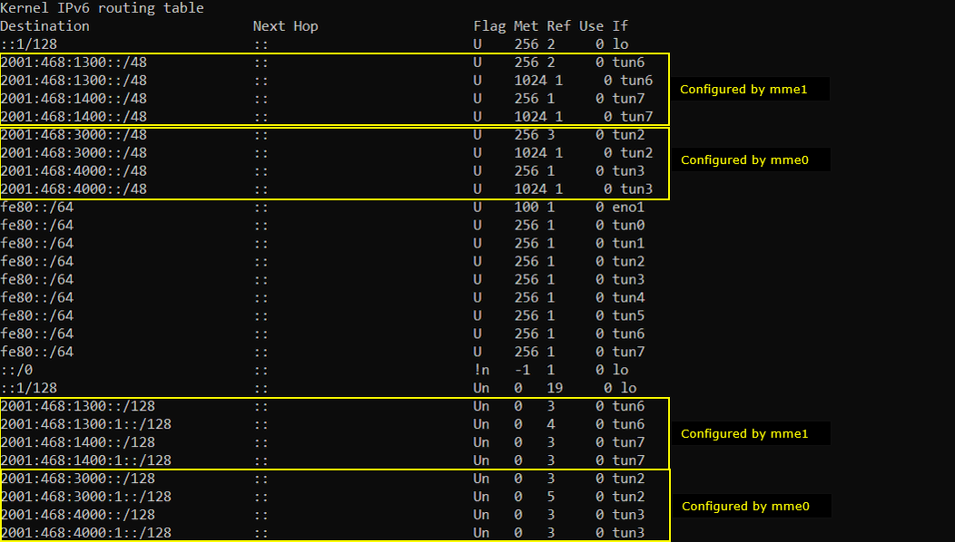
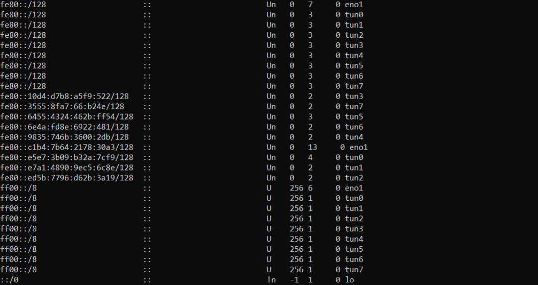
Followings are the ipv6 routing table created by the operating system and lte service.
Now go back to lte service screen and check follows.
Check the mmes that the eNB is connected as shown below. (NOTE : It may take some time to get both of s1 to be printed as "setup_done'. Sometimes you may need to try s1 command several times until you see both of S1 are printed as 'setup_done'.

Go to MME (mme0) and check out the connected enb.

Go to MME1(mme1) and check out the connected enb.

Go to IMS (ims0) and check out the connected mme.

Go to IMS1 (ims1) and check out the connected mme.

Log Analysis
The screenshots below shows only the initial connection of each network components and SIB1 message from each cell. I have tried this with real UE and captured the full log from attach to IMS registration for both cells. Check out the Sample Logs.
If you run WebGUI, you would notice that a new component (MME1) is added as shown below.
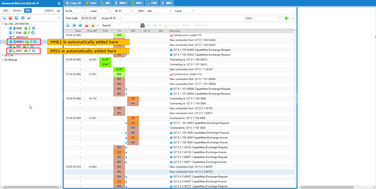
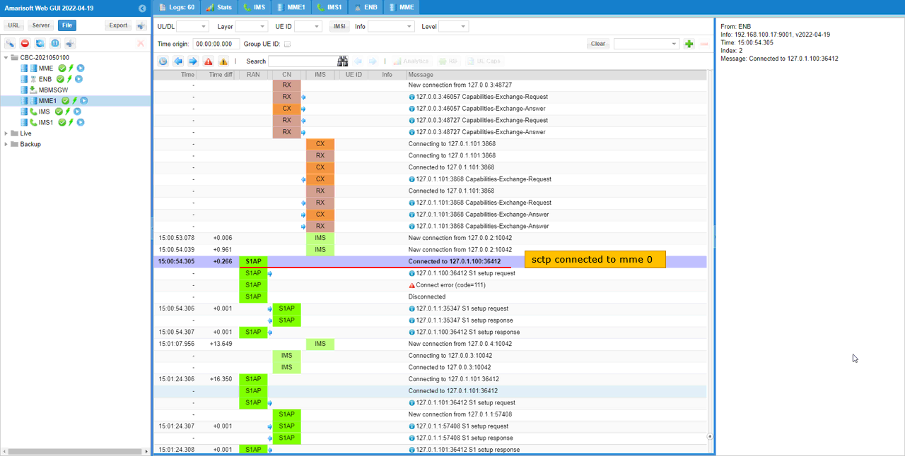
Followings are some of highlighted steps you may want to check.
This shows sctp socket is established with mme0(127.0.1.100).
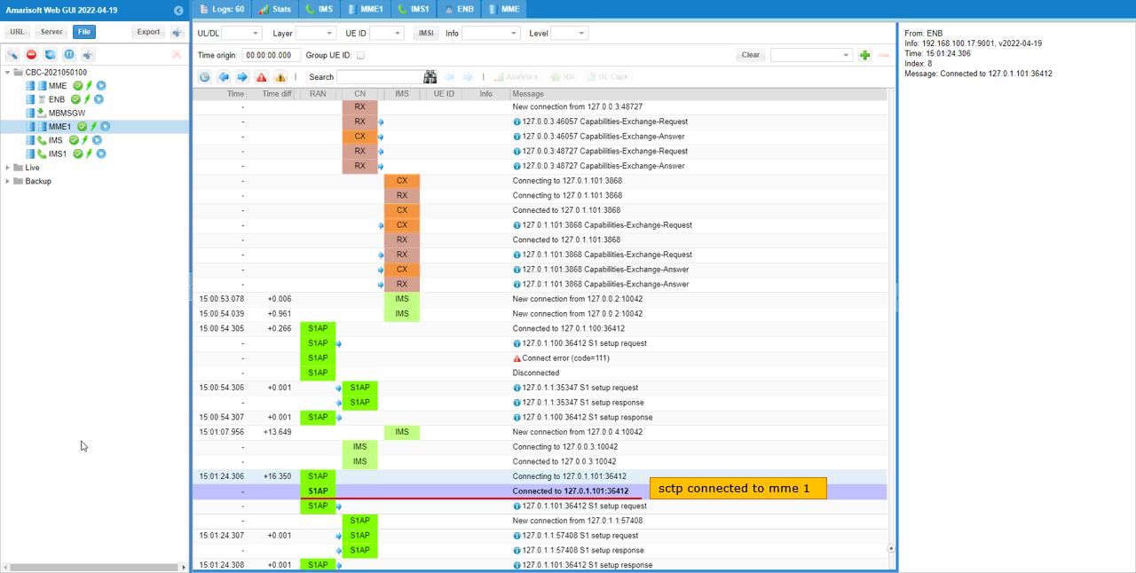
This shows sctp socket is established with mme1(127.0.1.101).
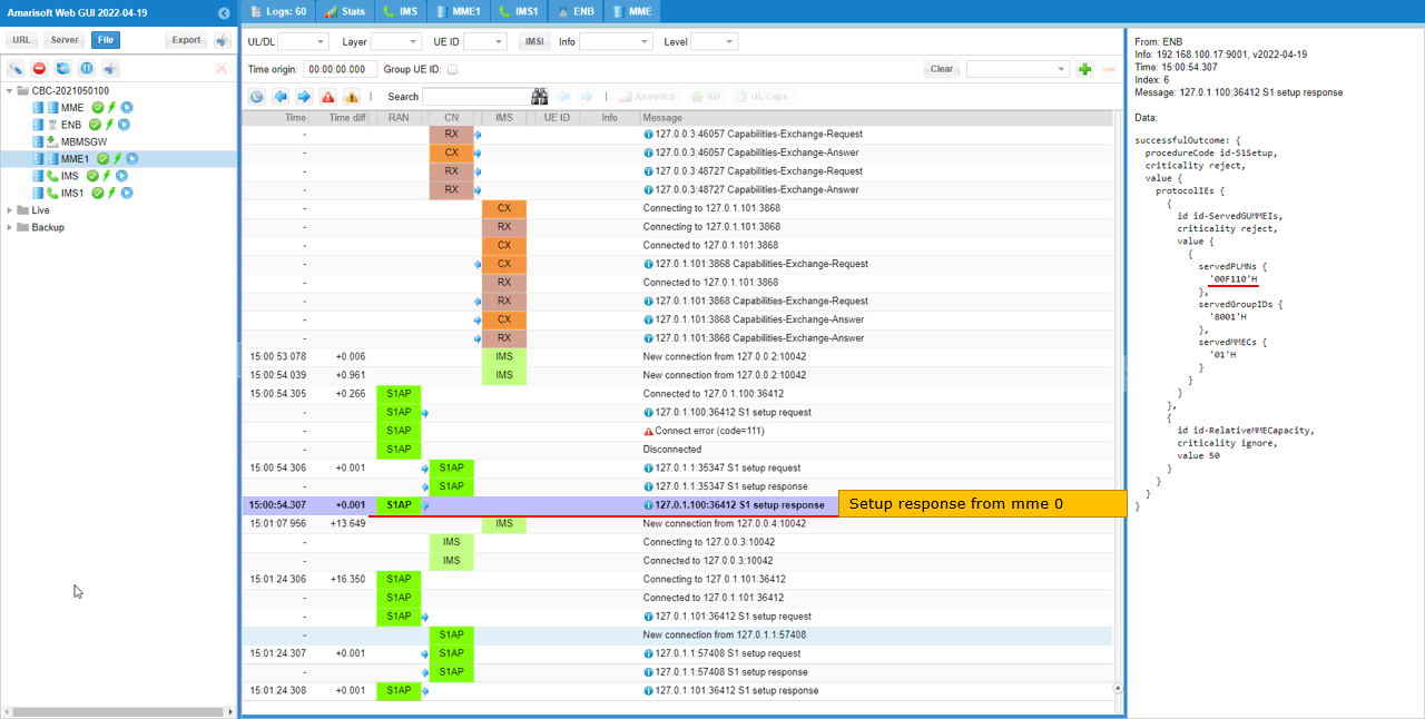
eNB send S1 setup request to mme0(127.0.1.100).
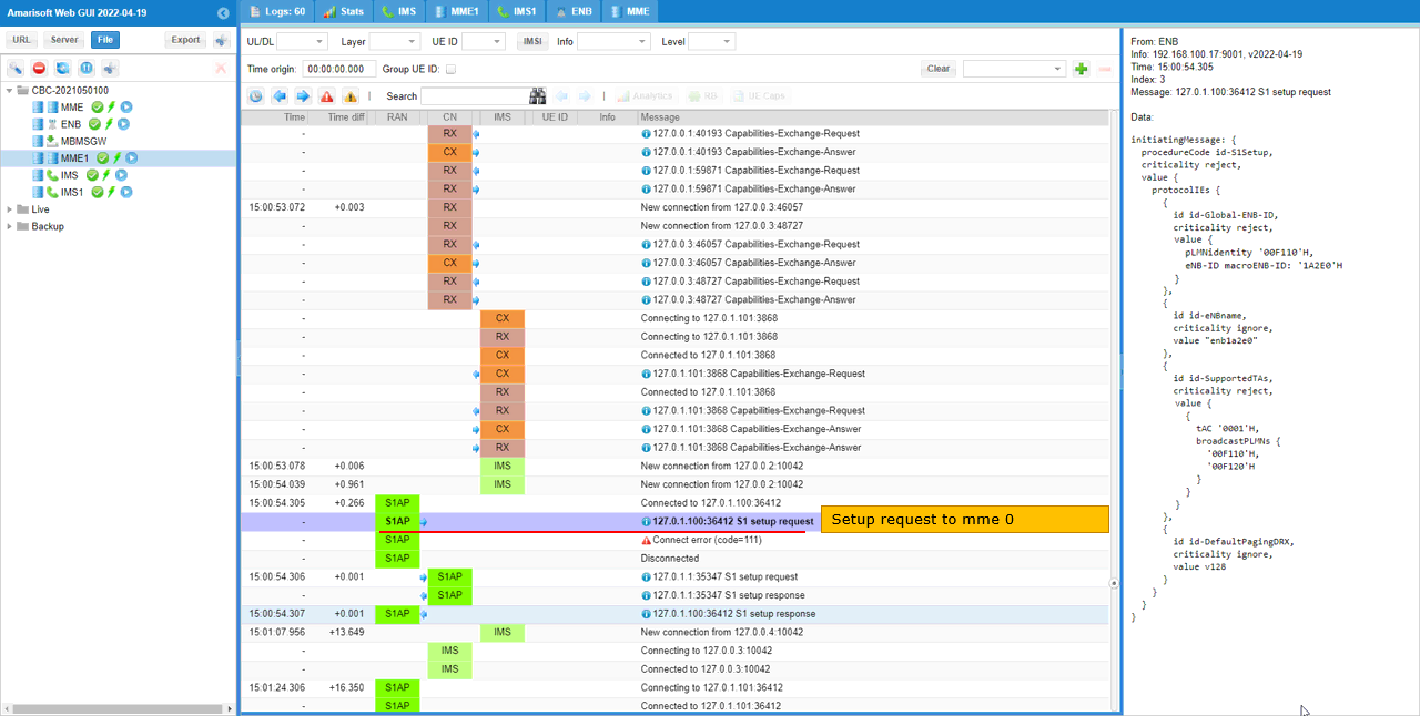
mme0 send S1 setup response to eNB. This indicates that S1AP between eNB and mm0 is established.
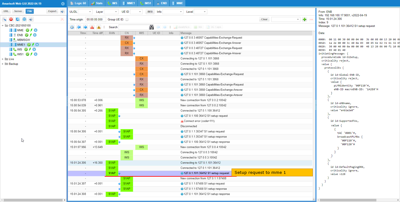
eNB send S1 setup request to mme1 (127.0.1.101).
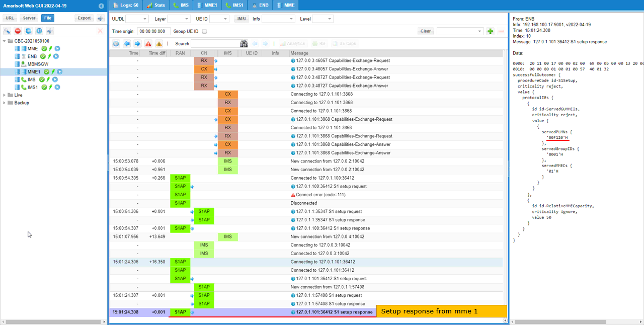
mme1 send S1 setup response to eNB. This indicates that S1AP between eNB and mm1 is established.
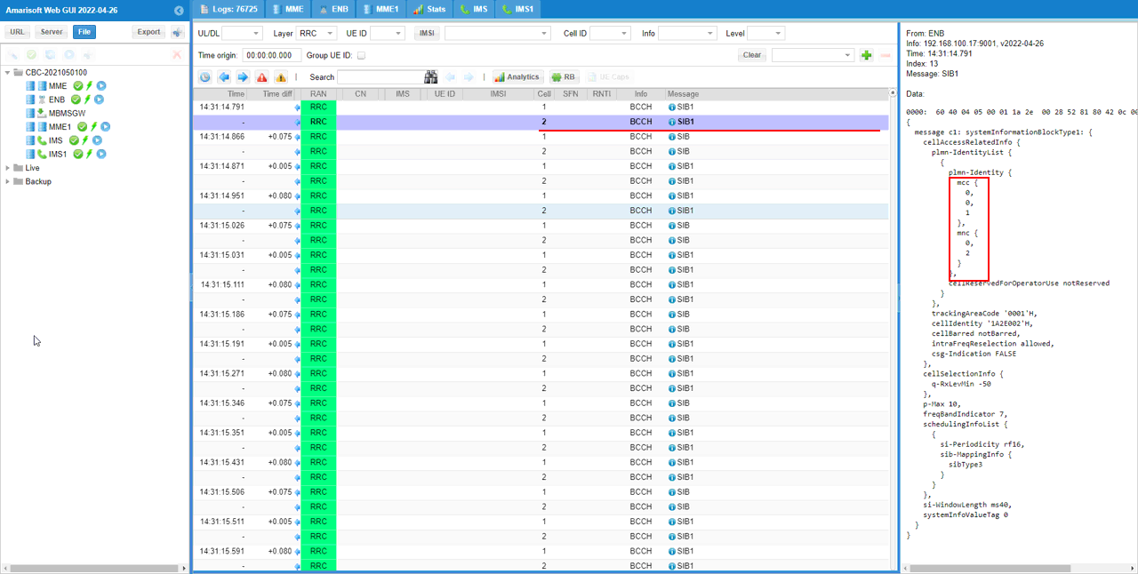
Now the Cell 1 is transmitting SIB1 with PLMN 001-01 as set in the configuration file..
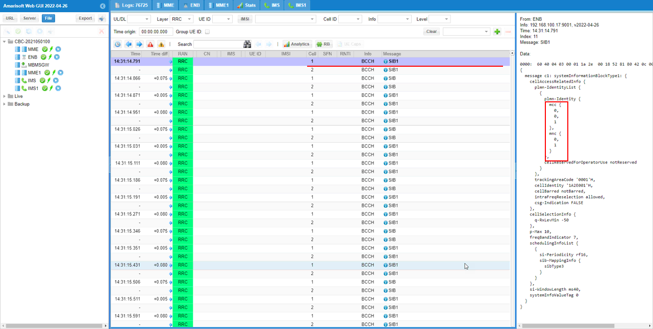
Then Cell 2 is transmitting SIB1 with PLMN 001-02 as set in the configuration file.
