UEsim LTE Multi UE
This tutorial is to show how to simulate multiple UEs with a single UEsim. For the simplicity, I am simulating only 5 UEs but you can simulate maximum of 500 or 1000 UEs with single Amari UEsim
One of the difficulties of performing this type of test is about how to automate UE operation. It would be challenging the operate each of the UE manually when the number of UEs are high. There are roughly three types of automating UE if you are using Amarisoft UEsim (If you are using commercial UEs, you need to come out with your own way of manipulating UEs). The first way is to test completely manual mode and another way is to use GUI based automation called Scenario which is provided by WebGUI and the last way is to use event settings in configuration file. In this tutorial, I will be doing all the test mannually. For the operation with Scenario, you may refer to this tutorial and for the operation with event settings in configuration file, you may refer to other tutorial.
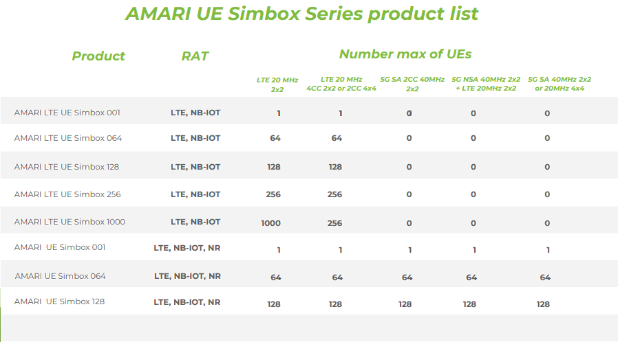
For further details of the specification of AMARI UE Simbox Series, refer to this product datasheet.
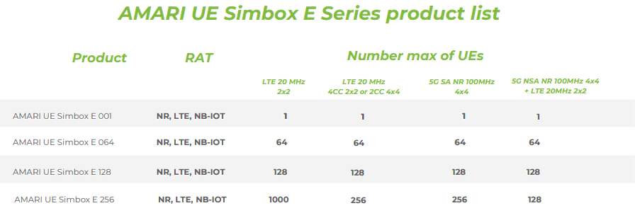
For further details of the specification of AMARI UE SimboxE Series, refer to this product datasheet.
For further details of the specification of AMARI UE Simbox MBS Series, refer to this product datasheet.
Table of Contents
Introduction
Simulating multiple User Equipments (UEs) with a single UE simulator is a critical technique in wireless network testing and validation, enabling engineers and researchers to model real-world scenarios without the need for extensive hardware resources. Amarisoft's AMARI UEsim is a software-based UE simulator capable of emulating hundreds to thousands of UEs over a single computing platform, supporting various radio access technologies such as LTE and 5G NR. This flexibility is essential for performing large-scale, repeatable, and automated testing of network functions, core integration, mobility procedures, and radio interface performance. Architecturally, UEsim abstracts physical devices into virtual entities, each with unique parameters such as IMSI, security credentials, and radio profiles, operating concurrently within a unified simulation environment. The solution is engineered to interact seamlessly with commercial and open-source network equipment, delivering high-fidelity protocol emulation across all layers of the cellular stack. The simulator supports several modes of operation—manual control, GUI-driven scenarios, and configuration-based event automation—enabling diverse test methodologies for exhaustive functional and performance verification. In modern wireless deployment and research, the ability to simulate multiple UEs is indispensable for validating network scalability, conducting interoperability tests, and accelerating product development cycles. This tutorial provides a practical guide to manually simulating multiple UEs using a single UEsim instance, highlighting key configuration steps, operational tips, and best practices tailored for scalable network testing.
-
Context and Background
- Amarisoft AMARI UEsim is a software solution designed to simulate large numbers of virtual UEs on a single hardware platform, supporting technologies such as LTE and 5G NR.
- Simulating multiple UEs is essential for evaluating network behaviors under high-load, multi-user scenarios, and for conducting regression and stress tests without deploying physical devices.
- The platform enables protocol-level emulation and supports integration with commercial and open-source network infrastructures.
-
Relevance and Importance of the Tutorial
- Demonstrates how to efficiently simulate multiple UEs in a controlled, repeatable manner using minimal physical resources.
- Addresses the challenge of automating UE operations and introduces different automation methodologies supported by UEsim.
- Provides practical insights into maximizing test coverage and scalability, which are crucial for network validation, optimization, and product development.
-
What Learners Will Gain
- Step-by-step guidance on configuring and initiating manual multi-UE simulations in UEsim.
- An understanding of the fundamental architectural concepts behind virtual UE simulation.
- Awareness of automation strategies and how to further extend simulations using scenario-based or configuration-driven automation.
- Familiarity with the practical limitations, licensing constraints, and scalability considerations of the UEsim platform.
-
Prerequisite Knowledge and Skills
- Basic understanding of LTE and/or 5G NR network architecture and protocol layers.
- Familiarity with Amarisoft UEsim installation and basic operation.
- Experience with network simulation environments and test automation concepts is beneficial.
- Access to a licensed UEsim platform with the required hardware and software specifications.
Summary of the Tutorial
This tutorial describes the procedure for conducting a multi-UE (User Equipment) LTE attach test using Amarisoft UEsim and Callbox. The focus is on configuring and verifying simultaneous registration and connectivity of multiple simulated UEs.
-
Test Setup:
- The test utilizes a SIM card provided with the system. Users may refer to the Configuration Guide if further changes are required.
- Test setup involves UEsim, Callbox (eNB, MME), and associated configuration files.
-
Key Configuration Parameters:
- On UEsim, parameters multi_ue, ue_count, and global_timing_advance are emphasized for proper multi-UE simulation.
-
Configuration Steps:
- Copy and modify ue.default.cfg to create ue.default-multi-ue.cfg for multi-UE support.
- Use enb.default.cfg (default LTE eNB configuration) on Callbox.
- Configure mme-ims-multi-ue.cfg on the MME, ensuring ue_db-ims-multi-ue.cfg is referenced for SIM information management.
- In ue.default-multi-ue.cfg:
- Set multi_ue to true.
- Set ue_count to the number of simulated UEs (e.g., 5).
- If sim_algo is set to "xor", only the starting IMSI is required; IMSI values auto-increment for each UE.
- On enb.default.cfg, optionally set the inactivity_timer to 1 minute (60000 ms) to allow sufficient time for all UEs to register before RRC release.
- Ensure that IMSI and K values match between UEsim and Callbox configurations.
-
Test Execution Procedure:
- Start trace logging on Callbox to monitor the attach process.
- Power on all configured UEs simultaneously on UEsim.
- Observe trace logs on Callbox and confirm that all UEs complete the attach procedure.
-
Use the 'ue' command on UEsim to verify the status of all UEs:
- Check that each UE appears under the UE_ID column and that its EMM_STATE is marked as 'registered'.
- On Callbox (eNB), use the 'ue' command to display connected UEs. Note that only UEs in connection mode will appear.
- On Callbox (MME), use the 'ue' command to verify that all UEs are registered (REG column marked 'Y') and have unique SUPI values.
- Conduct connectivity verification by pinging each IP address assigned to the UEs from Callbox to ensure data path establishment.
-
Log Analysis:
- The primary focus during log analysis is to confirm that each simulated UE initiates an attach request with a unique IMSI value.
- The tutorial does not require detailed step-by-step log review, as the procedures follow standard LTE attach flows.
In summary, the tutorial guides the user through configuring, executing, and verifying a multi-UE LTE attach scenario, emphasizing correct parameter setup and status validation via command-line and logging tools.
Test Setup
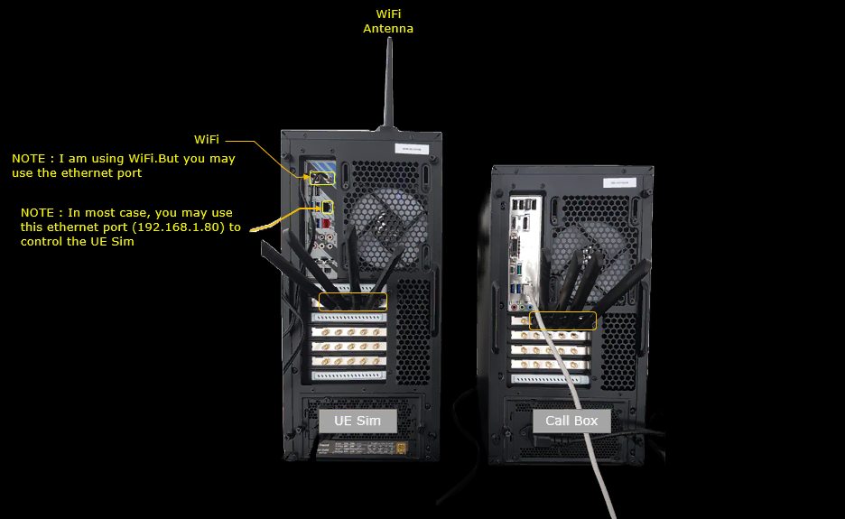
Test setup for this tutorial is as shown below.
- SIM Card used in this tutorial is the one delivered with the system as it is.
- If you want to change the configuration, The tutorial Configuration Guide would help
The UEsim is the box on the left and the Callbox is the one on the right. Only one RF slot is used on each side, and a single cable runs between the two marked slots. All 5 UEs of this test share that one RF connection.
I am controlling the UEsim over WiFi here, through the WiFi card and the antenna above it. You do not have to do it this way. The ethernet port marked just under the WiFi card is the usual control path, and it sits at 192.168.1.80 in most installations.
Key Configuration Parameters
Followings are important configuration parameters for this tutorial. You may click on the items for the descriptions from Amarisoft documents.
- UEsim
- Callbox
Configuration
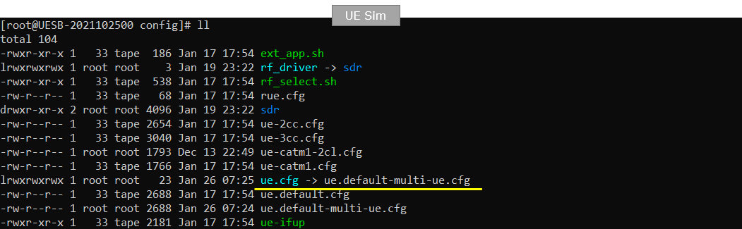
I used the ue.default-multi-ue.cfg which is copied and modified from ue.default.cfg (LTE default configuration).
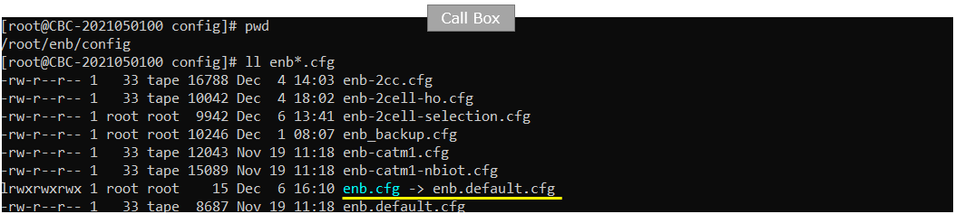
I used the enb.default.cfg (LTE default configuration).
I used the mme-ims-multi-ue.cfg which is copied and modeified from mme-ims.cfg
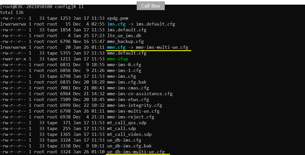
In the mme-ims-multi-ue.cfg, I changed the configuration so that ue_db-ims-multi-ue.cfg is used on Callbox.
The subscriber data is not held in mme-ims-multi-ue.cfg itself. It is pulled in with a single include line under the user data base comment. Changing that one file name is the whole edit.
The original ue_db-ims.cfg is still sitting in the same directory. You can go back to the stock subscriber set at any time by putting its name here instead.

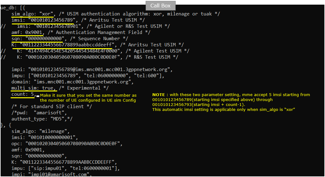
In this tutorial, following SIM information will be used within ue_db-ims-multi-ue.cfg. Make it sure to configure the same parameters on UE side as well. If you are using "xor" algorithm, you don't have to configure every UE with different imsi. You just put the starting imsi value and MME and UEsim will automatically handle the automatically incremented IMSI values.
The first entry of ue_db is the one used in this test. sim_algo is xor, imsi is 001010123456789 and K is 00112233445566778899aabbccddeeff. sqn is left at the default 000000000000. For the XOR algorithm the actual sqn value does not matter. The imsi and K lines commented out around them are the values for Agilent and R&S test USIMs.
count is set to 5 and that is the parameter which creates the extra subscribers. The MME builds 5 user entries by incrementing the IMSI and the K from the starting values. The IMSIs it ends up accepting run from 001010123456789 through 001010123456793. Set count to the same number of UEs you configure on the UEsim side. If it is smaller, the last UEs will find no matching subscriber and the attach fails.
multi_sim is set to true in the same entry. It is only allowed with the XOR algorithm, which is what this entry uses.
A second ue_db entry follows below, with sim_algo milenage and imsi 001010000000001. It is not used in this tutorial.
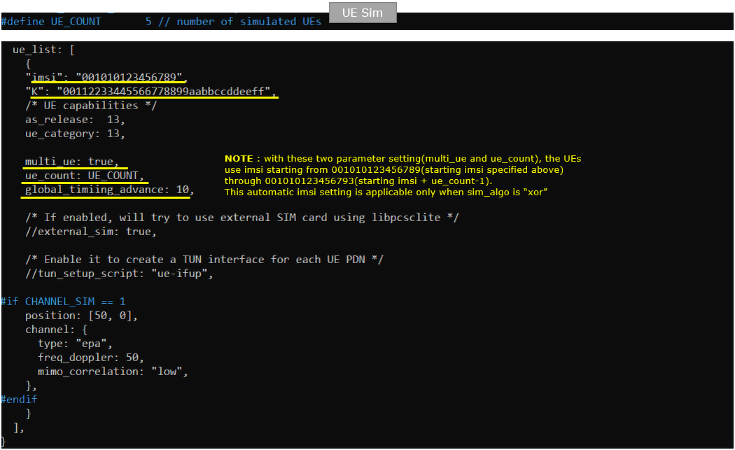
In ue.default-multi-ue.cfg on UEsim, Make it sure that imsi and K value in this file matches the value on enb side shown in previous slide. You see here that multi_ue is set to true and ue_count is set to the number greater than 1. If authentication algorithm (sim_algo) is set to "xor", IMSI automatically increment from the starting value through (starting imsi+ue_count-1)
multi_ue set to true is what puts UEsim into multiple UE mode. With it set to false you get the real UE mode with a single instance. ue_count does not carry a number directly. It takes the UE_COUNT macro defined at the top of the same file, and that is 5 here.
UEsim then creates 5 user entries by incrementing the IMSI and the K from 001010123456789, so the last one is 001010123456793. The same 5 entries have to exist on the MME side. That is what count: 5 in ue_db does.
global_timing_advance is set to 10. This parameter is only meaningful in multiple UE mode. It fixes the uplink timing advance relative to the downlink, and the unit is 1/1.92 us for an LTE cell. The default value is -1, which tells UEsim to use the timing advance from the first received RAR instead.
The rest of the entry is not exercised in this test. as_release and ue_category are both 13, external_sim and tun_setup_script are left commented out, and the CHANNEL_SIM branch only takes effect when the file is built with CHANNEL_SIM set to 1.
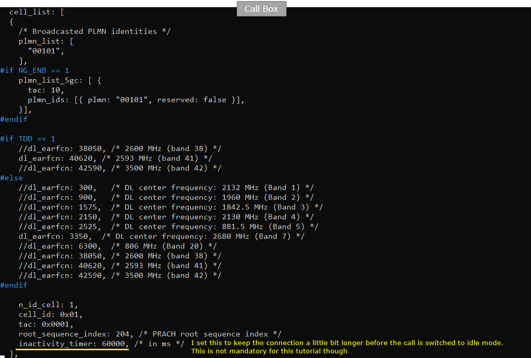
Following is the configuration in enb.default.cfg on Callbox. The parameters here is not critical for multi UE test. You can use any settings as long as there is not problem with the attach.
The cell in this run is FDD, since TDD is 0. N_RB_DL is 25, which is a 5 MHz cell. N_ANTENNA_DL and N_ANTENNA_UL are both 1, so the cell is SISO. CHANNEL_SIM is 0 and NG_ENB is 0, so the channel simulator is off and the eNB is not acting as an ng-eNB.

This is optional. In enb.default.cfg, I made a small change as shown below. I set the inactivity_timer to 1 minutes (60000 ms) to wait for enough time untill all the UE are registerred before releasing RRC (This is not mandatory)
inactivity_timer makes the eNB send an RRC connection release after that many ms of network inactivity. At 60000 ms the 5 UEs stay in connected mode much longer. You get time to run the ue command on the UEsim, on the eNB and on the MME before any of them drops to idle. Lower it back if you would rather watch the release happen.
The rest of the cell is the stock configuration. The broadcast PLMN is 00101, n_id_cell is 1, cell_id is 0x01, tac is 0x0001 and root_sequence_index is 204. TDD is 0 in this build, so the #else branch is taken and dl_earfcn is 3350. That is a DL center frequency of 2680 MHz in band 7.
The plmn_list_5gc block above is not used, because NG_ENB is 0.
Following is the configuration in ue.default-multi-ue.cfg on UE sim. Set UE_COUNT to 5 (whatever number you want) and other parameters are not important for this test.
UE_COUNT is the macro that ue_count reads in the ue_list entry. Raising it here is the only change needed on the UEsim side to simulate more UEs. Remember to raise count in ue_db on the MME side by the same amount.
The other defines line up with the eNB side. TDD is 0 for FDD and CELL_BANDWIDTH is 5 for a 5 MHz cell. Both antenna counts are 1, and CHANNEL_SIM is 0 so the UE channel simulator is off.

Perform the test
Start trace logging on Callbox.
The command is a single t typed at the (enb) prompt of the Callbox console. The trace then keeps printing until you press return again. Start it before you power the UEs on, otherwise you miss the attach.

Power on UE on UE sim. '*' indicates powering on all the UEs configured.
This one is typed at the (ue) prompt of the UEsim console, not on the Callbox. With the 5 UEs configured in this test, one power_on * brings all 5 of them up at the same time.

Then you see following traces on Callbox and confirm all the UEs get attached. You can check out which UEs are camped on via the numbers under UE_ID column.
Five PRACH lines come first, one for each UE. Each line gives the preamble sequence, the timing advance and the SNR, for example seq=15 ta=4 snr=20.8 dB. Five lines is what you want to see. More than five means some of the RACH attempts failed and were retried.
The table below has one row per UE. UE_ID runs from 5 down to 1, and each UE holds its own RNTI, from 0x0041 down to 0x003d. Five distinct UE_ID values is the check that all five got onto the cell. CL reads 001 on every row, so they are all on the same cell.
The two blocks are two reporting intervals. In the first one cqi is 3 and the DL mcs sits between 1.0 and 2.0. In the second one cqi has come up to 5 and the DL mcs is between 6.7 and 8.8, with the UL snr in the 30 to 39 dB range.

You can check the list of all the UE status with 'ue' command on UE sim. Make it sure that you see all the UE under 'UE_ID' column and the EMM_STATE of all the UE is marked 'registered'.
The leading # column is only the row index and it runs 0 to 4. UE_ID is the identifier you use in commands, and it runs 1 to 5. All five rows are marked 4G, RRC_STATE is running on every one, and #ERAB is 1 so each UE has one bearer up.
IP_ADDR holds the address the core assigned to each UE. They are all different: 192.168.2.18, 192.168.2.2, 192.168.2.6, 192.168.2.10 and 192.168.2.14. These are the addresses to ping later. The RNTI column carries the same 3d to 41 values that the eNB trace printed.

You can check the list of all the UE status with 'ue' command on (enb) on Callbox. The UE ID will be shown here only when a UE is in connection mode. So it is OK if you don't see all the UEs here.
All five UEs are still in connected mode in this run, so all five rows are present. RAN_UE_ID is the identifier the eNB uses and CN_UE_ID is the one the core uses for the same UE. The two do not run in step. RAN_UE_ID 5 maps to CN_UE_ID 104 and RAN_UE_ID 1 maps to 100.
Cell is 0x001 on every row, and the RNTI values are the same 0x003d to 0x0041 seen in the trace. A UE that has gone to idle disappears from this list. It is still there in the MME list below.

You can check the list of all the UE connected to MME with 'ue' command on (mme) on Callbox. Make it sure that you see all the UEs shown here with different SUPI and all UE is marked 'Y'(Yes) under REG column.
The five SUPI values run from 001010123456789 to 001010123456793. That is the starting IMSI through the starting IMSI plus count minus 1, which is exactly what count: 5 in ue_db was set up to produce. Each row also carries its own IMEISV, from 0123456700000101 to 0123456700000501.
CN reads EPC on every row, so all five attached to the LTE core rather than to 5GC. Each UE has one bearer and its own M-TMSI. The IP_ADDR column holds the same five addresses the ue command listed on the UEsim. Both sides agree on which UE got which address.

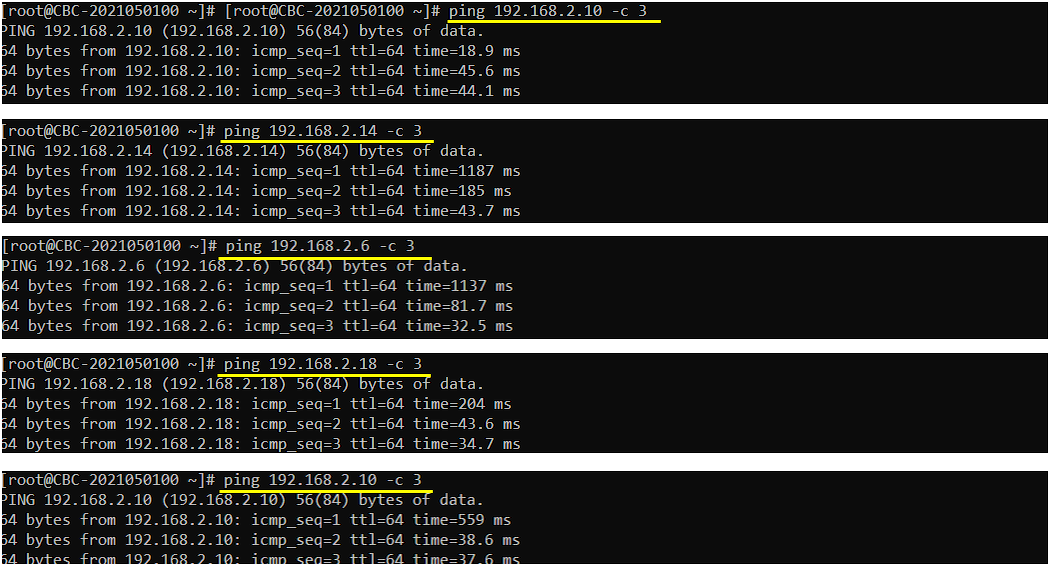
You may try ping from Callbox to all of the UEs. ping to each and every IPs that are assigned to each UE.
Each ping is run with -c 3, so it sends three requests and then exits. All three are answered every time, with ttl 64. The addresses come straight from the IP_ADDR column of the ue command output.
The first reply of each burst is usually the slowest one, up to 1187 ms on 192.168.2.14. The replies after it settle in the 30 to 50 ms range. If a ping gets no answer at all, check that the UE is still listed by the ue command before you look anywhere else.
Log Analysis
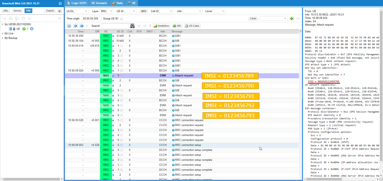
I would not go through all the log since this would just be the repetition of basic LTE attach procedure. The only thing that I want to highlight is the Attach Request from UE sim log showing different IMSI values for each UE as shown below.
Five Attach request messages appear on the EMM layer, one from each UE, and the UE ID column keeps them apart. The IMSI in each one is different. They run 001010123456789, then 790, 791, 792 and 793. That is the automatic increment from the starting IMSI arriving at the network.
The decode of the first one is on the right. Message type is 0x41 for Attach request and EPS attach type is 1 for EPS attach. The security header is 0x0, so this first NAS message goes as a plain message with no integrity protection. The identity carried is the IMSI itself and not an old GUTI.
The ESM message container inside it is a PDN connectivity request with request type 1 and PDN type 3, so IPv4v6 is asked for. The protocol configuration options ask for the P-CSCF and DNS server addresses on both IPv4 and IPv6. Below the five attach requests you see the RRC connection request, connection setup and connection setup complete for each of the five UEs.