
UEsim LTE Handover - LTE to NR
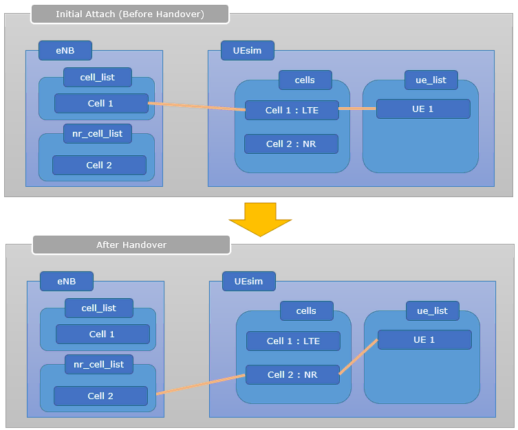
The overall callbox logic and 3GPP related with UEsim Handover is same as in Commercial UE handover. The main focus on this tutorial is to highlight on UEsim side configuration for LTE to NR handover. Since the configuration on UEsim for handover can be a little bit complicated, I would like you to have some big picture on the call box and UEsim configuration and relationship between them as illustrated below.
What I want to highlight is that you need to configure multiple cells not only in eNB side, but also in UEsim side. In commercial UE, you don't have to care about this since all of those configuration is done internally.
- LTE to LTE Handover IntraFrequency (Commercial UE)
- LTE to LTE Handover InterFrequency (Commercial UE)
Table of Contents
- UEsim LTE Handover - LTE to NR
Introduction
Handover procedures are a critical aspect of modern cellular networks, enabling seamless mobility and connectivity as a user equipment (UE) moves between different cells or radio access technologies. In the context of 3GPP-compliant systems, particularly LTE (Long Term Evolution) and NR (New Radio, 5G), handover mechanisms facilitate the uninterrupted transfer of active sessions and maintain service continuity for end-users. This tutorial focuses on the technical configuration of UEsim—a test UE simulator—specifically for LTE to NR handover scenarios. Unlike commercial UEs, where handover configuration is managed internally and remains transparent to the end-user, UEsim requires explicit manual configuration of multiple cells on both the callbox (network simulator) and the UEsim itself. This distinction is essential for engineers and testers who need fine-grained control and visibility into the handover process for validation, troubleshooting, and optimization purposes. Architecturally, the callbox emulates the network side, including eNB (Evolved NodeB for LTE) and gNB (Next Generation NodeB for NR), while UEsim acts as a highly configurable UE endpoint. The interaction between these elements and the necessity for precise alignment of radio parameters and cell configurations underscore the complexity of handover testing in a simulated environment. Understanding these concepts and the relationship between the callbox and UEsim is paramount for successful execution of LTE to NR handover scenarios and for gaining insights into protocol behavior, network interoperability, and system performance in evolving 5G ecosystems.
-
Context and Background
- 3GPP Handover Fundamentals: Handover enables UEs to maintain connectivity as they move between cells or access technologies, minimizing dropped calls and interrupted data sessions.
- Role of UEsim and Callbox: UEsim is a UE simulator used for protocol testing and development, while the callbox emulates the network side, including various cell configurations and radio parameters.
- Architectural Overview: The handover process involves coordinated actions between the eNB/gNB (on the callbox) and the UEsim, requiring explicit configuration of serving and target cells on both sides.
-
Relevance and Importance of the Tutorial
- This tutorial addresses the unique challenges of configuring UEsim for LTE to NR handover, a process that is abstracted in commercial UEs but critical for development, testing, and validation.
- It provides essential knowledge for network engineers, testers, and researchers involved in protocol conformance, interoperability, and performance evaluation in multi-RAT (Radio Access Technology) scenarios.
-
What Learners Will Gain
- An in-depth understanding of UEsim and callbox interaction for handover scenarios.
- Step-by-step knowledge of configuring multiple cells in both the callbox and UEsim for seamless LTE to NR handover.
- Practical insights into troubleshooting and optimizing handover procedures in a controlled test environment.
-
Prerequisite Knowledge and Skills
- Familiarity with LTE and NR (5G) architecture and terminology.
- Basic understanding of radio network simulation tools such as callboxes and UE simulators.
- Experience with network protocol testing and configuration processes is recommended for maximum benefit.
Summary of the Tutorial
This tutorial describes the test procedure for validating LTE to NR (5G) handover, specifically triggered by eNB (LTE cell) power change. It covers the test setup, key configuration parameters, detailed configuration steps, execution of the test, and log analysis methodology. The summary below captures the main test procedures and flow, preserving the original document’s formatting and structure.
- Test Setup
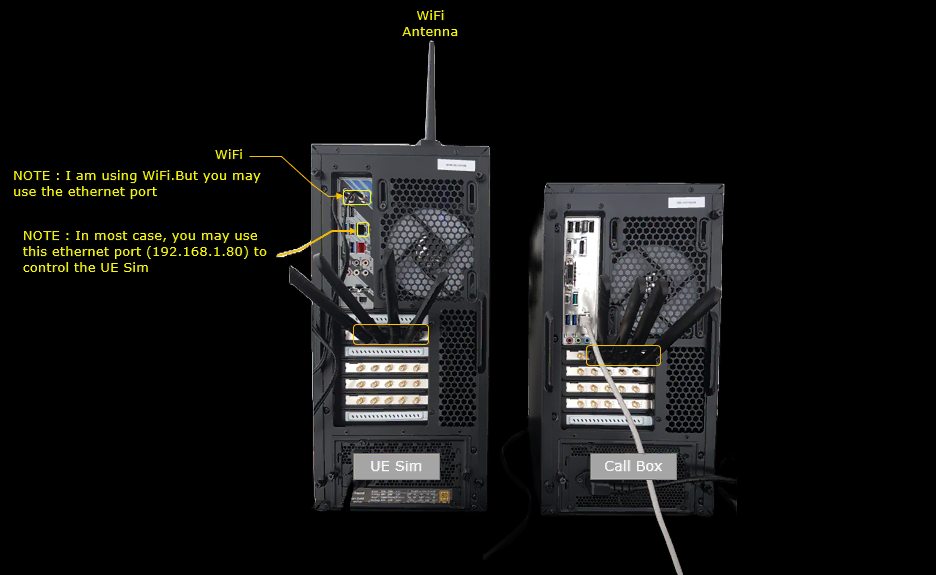
- Antennas must be connected to at least two SDR cards on both Callbox and UEsim.
- Test setup involves a Callbox emulating two cells (LTE and NR), and a UEsim configured for dual-cell operation.
- Key Configuration Parameters
- Important parameters that must be configured include:
- ncell_list (neighbor cell list), including rat and cell_id
- meas_config_desc (measurement configuration), including event triggers, thresholds, hysteresis, time to trigger, and nr_handover settings (e.g., b2_threshold1_rsrp, b2_threshold2_rsrp)
- meas_gap_config, ho_from_meas
- On UE side: cell_groups, cells, ue_list
- Important parameters that must be configured include:
- Test 1: LTE to NR Handover / Triggered by eNB Power Change
- Configuration Steps
- Use enb-2cell-ho-irat-b1-n78.cfg on the Callbox for eNB, configuring two cells (LTE and NR). Set ALLOW_SA to 1 for dual operation.
- For the LTE cell, configure ncell_list to include the NR cell (e.g., n_id_cell : 2).
- For the NR cell, ncell_list is not set, enabling only LTE→NR handover (not NR→LTE). To test bidirectional handover, configure ncell_list for the NR cell as well.
- In the cell_default configuration, set meas_config_desc to trigger handover only upon the expected measurement report, and increase inactivity_timer to allow time for cell power tweaking.
- Tweak b2_threshold1_rsrp and b2_threshold2_rsrp for the measurement report to trigger before the link is lost (due to UEsim’s limited dynamic range).
- Configure mme-ims-irat.cfg for the MME and ue-ho-irat-LN.cfg for the UE simulation, ensuring N_CELL is set to 2 and that each simulated UE cell matches the corresponding Callbox cell in dl_earfcn and bandwidth.
- Test Execution Steps
- Verify cell configuration with cell phy and cell commands.
- Optionally, log SIB messages briefly with log bcch to verify SIBs for each cell, then stop SIB logging to keep logs manageable.
- Set appropriate tx_gain or, preferably, adjust cell_gain on both cells to control cell power for triggering measurement reports (recommended to use cell_gain to avoid changing SIB1 reference power).
- On UEsim, use the cells command to check for PCI values, confirming that both cells are detected.
- Power on the UE on UEsim.
- Observe initial attach; then tweak cell power to trigger the measurement report and handover. Indications of successful handover include observing two RACH attempts: one to the LTE cell and one to the NR cell.
- Log Analysis Methodology
- Verify that the eNB sends RRC Connection Reconfiguration with correct measurement configuration.
- Check that measObjectToAddModList includes the frequencies for both source (LTE) and target (NR) cells.
- Ensure reportConfigToAddModList includes expected events (A1, A2, B2).
- Confirm measIDToAddModList maps measurement IDs to the correct measurement objects and report configs.
- Observe that the UE sends the measurement report for the B2 event (for NR cell).
- Verify the sequence of handover signaling messages (e.g., "Handover required", "Handover Request", "Handover command", "Mobility from EUTRA command", and UE's response with "RRC Reconfiguration complete").
- Upon handover completion, confirm that the UE goes through registration on the target (NR) cell and that the cell switch is reflected on the PHY layer (e.g., via RB map).
- Configuration Steps
Note: The tutorial emphasizes the importance of careful configuration of measurement reporting thresholds and neighbor cell lists, as well as using appropriate commands and log analysis to verify that the LTE to NR handover is triggered and processed as intended. The steps above should be followed precisely to ensure reliable and reproducible results.
Test Setup
Test setup for this tutorial is as shown below. (
Key Configuration Parameters
Followings are important configuration parameters for this tutorial. You may click on the items for the descriptions from Amarisoft documents.
- ncell_list : In this link, you would get the descriptions for all the items listed below
- rat
- cell_id
- meas_config_desc : In this link, you would get the descriptions for all the items listed below
- a1_report_type
- a1_rsrp
- a1_hysteresis
- a1_time_to_trigger
- a2_report_type
- a2_rsrp
- a2_hysteresis
- a2_time_to_trigger
- nr_handover
- b2_threshold1_rsrp
- b2_threshold2_rsrp
- hysteresis
- time_to_trigger
- meas_gap_config
- ho_from_meas
- eps_5gs_interworking : this is the corenetwork side parameter that enables the EPS to 5GS interworking used by this handover
- cell_groups
- ue_list : In this link, you would get the descriptions for all the items listed below
- n1_support
Test 1 : LTE to NR Handover / Triggered by eNB Power Change
This test is to show how to test LTE to NR handover triggered by cell power change from callbox (eNB).
Configuration
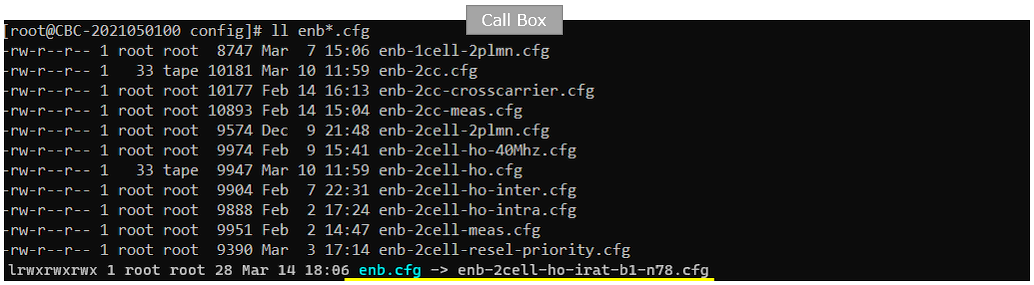
I used the enb-2cell-ho-irat-b1-n78.cfg on gNB which is copied and modified from gnb-nsa.cfg
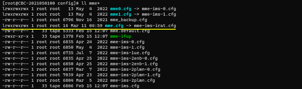
I used the mme-ims-irat.cfg on gNB which is copied and modified from mme-ims.cfg
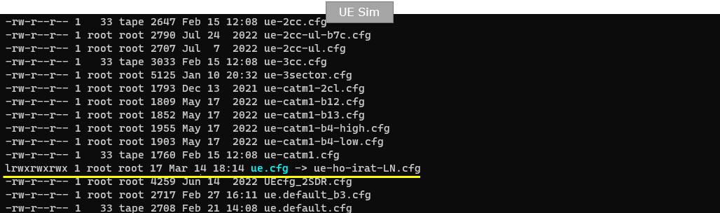
I used the ue-ho-irat-LN.cfg on gNB which is copied and modified from ue- ue-nr-nsa.cfg
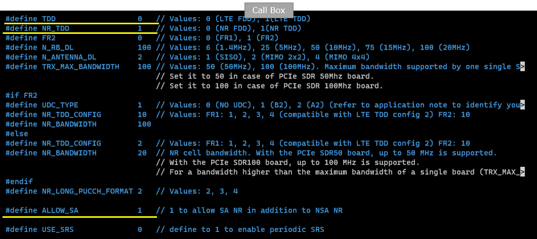
In enb-2cell-ho-irat-b1-n78.cfg , the configuration is done as follows. Since this is based on gnb-nsa.cfg, the two cell (LTE and NR) are configured by default. Just to note is to set ALLOW_SA to 1 to make both cell function as camping cell.
ALLOW_SA is set to 1 and the comment on that line reads "1 to allow SA NR in addition to NSA NR". Without this, the NR cell of gnb-nsa.cfg would only work as an NSA secondary cell, and it could not be used as the target of an LTE to NR handover because the UE has to camp on it as a standalone cell after the handover.
The duplex mode of the two cells is set separately. TDD is 0, so the LTE cell is FDD, while NR_TDD is 1, so the NR cell is TDD. FR2 is 0, so the FR2 branch below is not used and the NR cell takes NR_TDD_CONFIG 2 and NR_BANDWIDTH 20 from the #else branch.
The remaining defines set the radio dimensions of the two cells. N_RB_DL is 100, which is the 20 MHz LTE bandwidth, N_ANTENNA_DL is 2 for MIMO 2x2, and TRX_MAX_BANDWIDTH is 100 for a PCIe SDR 100 MHz board. If you use a 50 MHz board, this has to be set to 50 as the comment in the file explains.
This is the configuration of the first cell(LTE cell in this test). It is important to note that you need to specify the second cell (n_id_cell : 2) into ncell_list(Neighbour cell list) configuration.
The ncell_list entry is written as rat: "nr" and cell_id: 0x02. The rat item is what makes this an inter-RAT neighbour rather than an LTE neighbour, and cell_id 0x02 is the cell_id of the NR cell defined in the nr_cell_list below. This is the entry that tells the eNB which cell it is allowed to hand the UE over to.
The rest of this cell is an ordinary LTE cell. It uses rf_port 0, plmn_list "00101", n_id_cell 1, cell_id 0x01, tac 0x0001 and root_sequence_index 120. Since TDD is 0, the #else branch is taken and dl_earfcn is 300, which is a DL center frequency of 2140 MHz in band 1.
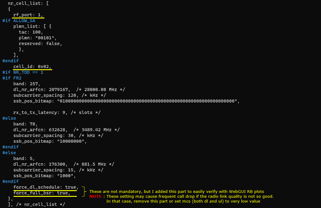
At the bottom, force_dl_schedule and force_full_bsr are both set to true. These are not mandatory. I added them only to make the handover easy to see in the WebGUI RB plots, because they keep both directions busy so the RB map is filled continuously. Be careful that these settings may cause frequent call drop if the radio link quality is not so good, in which case you should remove this part or set mcs for both DL and UL to a very low value.

This is the second cell (NR cell) configuration. In this configuration, I didn't set ncell_list here. This mean that you can test only LTE to NR Handover with this configuration. You cannot test NR to LTE Handover. If you want to bidirectional handover (i.e, both LTE to NR and NR to LTE handover), you need to configure ncell_list here as well.
This cell uses rf_port 1, which is the second RF port, so the LTE cell and the NR cell are transmitted from different SDR cards. This is why the test setup needs an antenna on at least two SDR cards as mentioned in the Test Setup section.
The plmn_list block of this cell is enclosed in #if ALLOW_SA, so it is only compiled in because ALLOW_SA was set to 1. It sets tac 100 and plmn "00101", which is the same PLMN as the LTE cell, and this is what allows the UE to register on this cell as a standalone NR cell after the handover. cell_id is 0x02, matching the ncell_list entry of the LTE cell.
Since NR_TDD is 1 and FR2 is 0, the band 78 branch is used. band is 78, dl_nr_arfcn is 632628 corresponding to 3489.42 MHz, subcarrier_spacing is 30 kHz and ssb_pos_bitmap is "10000000". The band 257 branch above and the band 5 branch below are the FR2 and NR FDD alternatives and they are not used in this test. force_dl_schedule and force_full_bsr are set to true here as well, with the same note as the LTE cell.
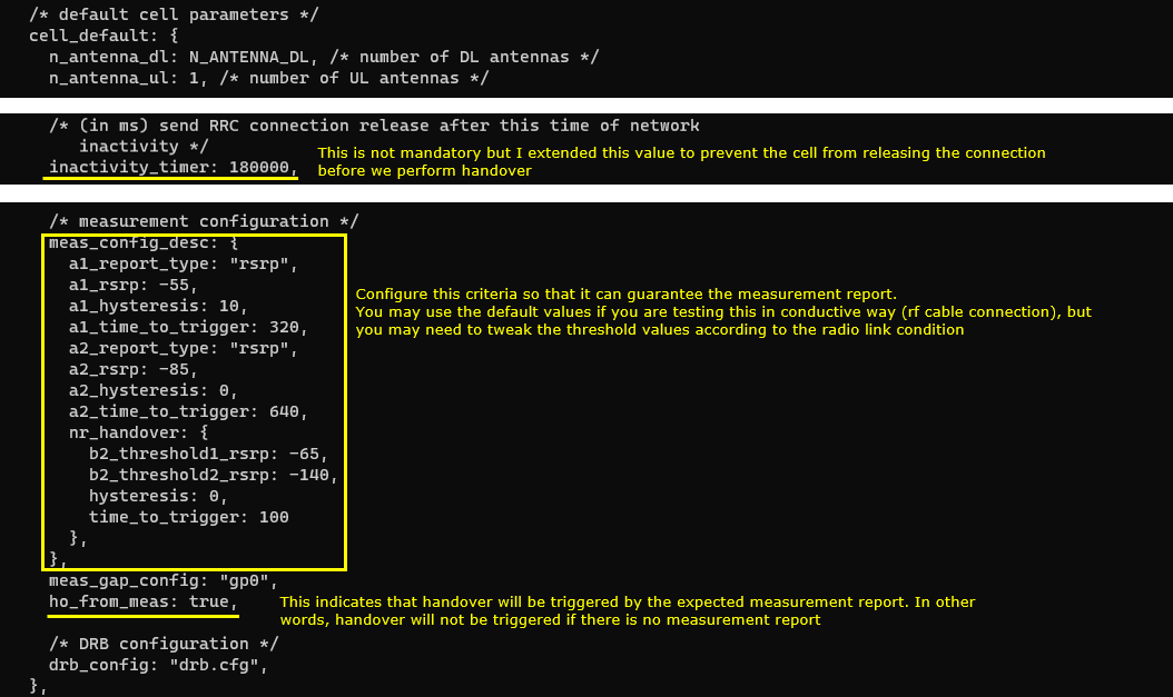
In cell_default configuration, I set meas_config_desc to trigger the handover only when the expected measurement report is recieved. I also increased the value for inactivity_timer just to give user enough time to tweak cell power to trigger appropriate measurement report.
ho_from_meas is set to true. This indicates that handover will be triggered by the expected measurement report, and in other words handover will not be triggered if there is no measurement report. This is the parameter that makes the whole test measurement driven, so if you leave it out the cell power tweaking done later would have no effect.
inactivity_timer is set to 180000. The comment in the file says this is the time in ms after which the RRC connection release is sent on network inactivity, and the note explains that this value was extended to prevent the cell from releasing the connection before we perform handover. Since the test requires you to change the cell power by hand after the UE attaches, the default value would be too short.
Within meas_config_desc, the LTE events use a1_report_type "rsrp" with a1_rsrp -55, a1_hysteresis 10 and a1_time_to_trigger 320, and a2_report_type "rsrp" with a2_rsrp -85, a2_hysteresis 0 and a2_time_to_trigger 640. The nr_handover block holds the inter-RAT B2 event with b2_threshold1_rsrp -65, b2_threshold2_rsrp -140, hysteresis 0 and time_to_trigger 100. b2_threshold1_rsrp applies to the serving LTE cell and b2_threshold2_rsrp applies to the target NR cell, so the report is sent when the LTE cell falls below the first threshold while the NR cell rises above the second one.
Configure this criteria so that it can guarantee the measurement report. You may use the default values if you are testing this in a conductive way with an RF cable connection, but you may need to tweak the threshold values according to the radio link condition. meas_gap_config is set to "gp0" so that the UE is given measurement gaps to measure the NR cell, and drb_config points to drb.cfg.
In mme-ims-irat.cfg, the configuration is done as follows.
eps_5gs_interworking is set to "with_n26". This is the parameter that enables EPS to 5GS interworking with the N26 interface between the MME and the AMF, and it is what allows the handover to be performed as a core network assisted procedure. This is the reason you later see the Handover required, Handover request and Handover command messages carrying the handover type eps-to-5gs in the log.
The other values are the usual corenetwork settings. com_addr is "[::]:9000" for the remote API and Web interface, gtp_addr is "127.0.1.100" so that ltemme can run on the same PC as lteenb, plmn is "00101" which matches the PLMN of both cells, mme_group_id is 32769 and mme_code is 1.
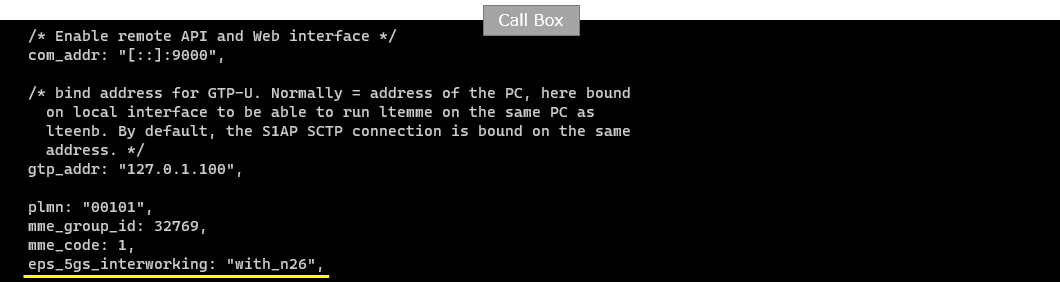
In ue-ho-irat-LN.cfg, the configuration is done as follows. Since this is a scenario that requires 2 cells, you need to set N_CELL to 2.
The other defines mirror the Callbox side so that the UEsim looks for the same two cells. TDD is 0 and NR_TDD is 1, matching the FDD LTE cell and the TDD NR cell of the eNB configuration, N_ANTENNA_DL is 2, and LTE_BANDWIDTH and NR_BANDWIDTH are both 20.

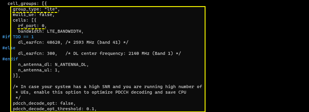
This is the cell configuration of the first cell. It does not require any specific configuration. You only neet to set dl_earfcn and bandwidth to match the configuration of the first cell on Callbox.
This is the first entry of cell_groups and it is marked with group_type: "lte", which is what makes this group the LTE side of the UEsim. rf_port is 0 and multi_ue is false.
Since TDD is 0, the #else branch is taken and dl_earfcn is 300 corresponding to a DL center frequency of 2140 MHz in band 1, which is the same value configured on the LTE cell of the Callbox. bandwidth takes the LTE_BANDWIDTH define, n_antenna_dl takes N_ANTENNA_DL and n_antenna_ul is 1, so the antenna configuration also matches the eNB side.
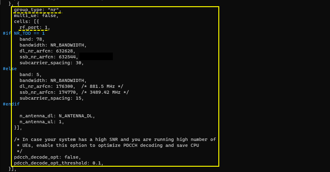
This is the second cell group and it is marked with group_type: "nr", so this is the NR side of the UEsim. It uses rf_port 1, which matches the rf_port 1 of the NR cell on the Callbox and is the reason the two cells have to be on different SDR cards.
Since NR_TDD is 1, the band 78 branch is used with dl_nr_arfcn 632628 and subcarrier_spacing 30 kHz, which are the same values as the NR cell of the Callbox. ssb_nr_arfcn is set to 632544 and this has to be given explicitly here because the UEsim needs to know where to look for the SSB. The band 5 branch below is the NR FDD alternative and it is not used in this test.
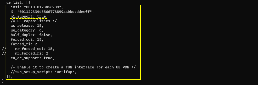
This is the configuration of the first ue It does not require any specific configuration. You only neet to set dl_earfcn and bandwidth to match the configuration of the second cell on Callbox.
n1_support is set to true. This is what makes the UE declare support for the N1 mode, that is the 5GS NAS, and it is required for this test because after the handover the UE has to run the 5GMM registration procedure on the NR cell that you see later in the log analysis.
The identity of the UE is set with imsi "001010123456789", which belongs to the PLMN 00101 configured on both cells, and the key K. as_release is 15 and ue_category is 6. en_dc_support is true, and forced_cqi 15 and forced_ri 2 are set so that the UE reports a fixed CQI and rank instead of a measured one. The nr_forced_cqi and nr_forced_ri lines are commented out, and so is the tun_setup_script line that would create a TUN interface for each UE PDN.
Perform the Test
Check if the cell is configured as intended. You can check these out with 'cell phy' and 'cell' command.
The header lines confirm that the single Callbox is running both nodes, showing [enb1a2d0] with PLMN=00101 eNB_ID=0x1a2d0 and [gnb0012345] with PLMN=00101 gNB_ID=0x12345. Both use the same PLMN, which is what the UE needs in order to move between them.
Cell 0x001 is the LTE cell. It is shown as RAT LTE on BAND 1 with BW 20 and P 0, which is rf_port 0. The DL uses ARFCN 300 with ANT 2, NL 2, SCS 15 and QAM 256, and the UL uses ARFCN 18300 with ANT 1, NL 1, SCS 15 and QAM 64. The SSB columns are empty because an LTE cell has no SSB.
Cell 0x002 is the NR cell. It is shown as RAT NR on BAND n78 with BW 20 and P 1, which is rf_port 1 as configured. The DL and UL both use ARFCN 632628 with SCS 30, and the SSB columns show ARFCN 632544 with SCS 30. This is worth checking here because the SSB ARFCN is the value the UEsim was given as ssb_nr_arfcn, and the two have to agree for the UEsim to find the NR cell.

This is not mandatory, but I would recommend to log SIB messages for a short time and stop so that you can confirm all the sibs for each cells. But I would not recommend you to capture the SIB log all the time since it may make it difficult to analyze other RRC / NAS messages. So I would just collect SIB log just a few seconds at the beginning and stop logging. You can do it with 'log bcch' command.
The sequence is log bcch=1, then wait for a few seconds, then log bcch=0, so that SIBs are collected only for a few seconds.

This is not mandatory, but set the proper tx_gain according to your test setup. (
In this example the value is set with tx_gain 70, and running tx_gain without an argument prints the resulting table. The table shows TX0 and TX1 on Port 0 and TX2 and TX3 on Port 1, all at 70.0 dB, so the command applies to both the LTE and the NR side at the same time. This is the reason the note suggests cell_gain when you want to move the two cells apart from each other, since tx_gain alone changes them together.

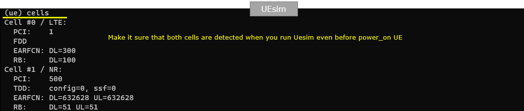
On UEsim, check out the result of 'cells' command. If you see the PCI values, it means the cell is detected (PSS/SSS detected).
Make it sure that both cells are detected when you run UEsim even before power_on UE. If only one of them appears here, there is no point in going further because the handover needs both.
Cell #0 is the LTE cell with PCI 1, shown as FDD with EARFCN DL=300 and RB DL=100. Cell #1 is the NR cell with PCI 500, shown as TDD with config=0 and ssf=0, EARFCN DL=632628 UL=632628 and RB DL=51 UL=51. The PCI 500 shown here is the value that appears again later in the measurement report as the reported NR neighbour cell.
Power on UE on UE sim.
Before the power_on command, the RF0 and RF1 lines show the two receivers of the UEsim. RF0 is on dl_freq 2140.000 MHz with ul_freq 1950.000 MHz in band 1, and RF1 is on dl_freq 3489.420 MHz with ul_freq 3489.420 MHz in band n78, both with sample_rate 23.040 MHz and dl_ant=2 ul_ant=1. These match the two cells configured on the Callbox.
After power_on, the log prints Cell 0: SIB found and Cell 1: SIB found. Make it sure that SIB detection for both cells are done. Detecting the PCI in the previous step only means the sync signals were found, while the SIB found message means the UEsim was able to read the broadcast information of each cell, which it needs before it can camp on either of them.

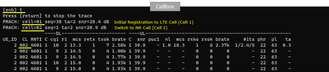
Check the initial attach and tweak the cell power to trigger measurement report and handover. Here you see the two RACH. The first RACH is to cell=01 and the second RACH is to cell=02, which implies that handover might have been triggered and cell switched to target cell.
This trace is obtained with the t command on the Callbox. The first PRACH line shows cell=01 with seq=38, ta=2 and snr=28.4 dB, and it is annotated as the initial registration to the LTE cell. The second PRACH line shows cell=02 with seq=1, ta=2 and snr=20.9 dB, and it is annotated as the switch to the NR cell. Since the UE never performs a random access on a cell it is not moving to, seeing a PRACH on cell=02 is the quickest sign that the handover actually happened.
In the table below, the CL column shows 002 for all the displayed rows, which means the UE is now counted on cell 2. The RNTI is 4601 and the DL rows show cqi 10 and mcs around 13 to 15 with txok increasing, so the UE is being scheduled on the NR cell after the switch.
Log Analysis
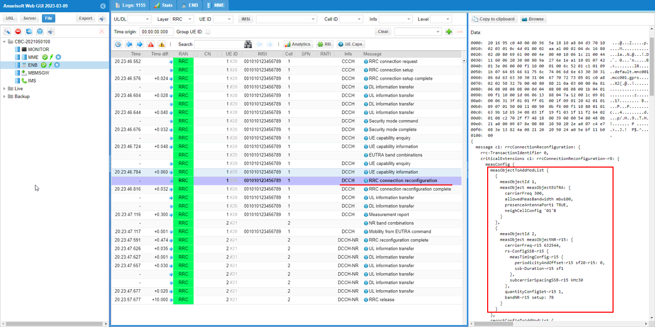
Since this test is for Handover based on measurement report, check if eNB transmits RRC Connection Reconfiguration with measurement configuration and see if the contents of the messages are all set as intended.
First check measObjectToAddModList and see the frequency of both the source and target cells are configured.
The list holds two measurement objects. measObjectId 1 is a measObjectEUTRA with carrierFreq 300, allowedMeasBandwidth mbw100, presenceAntennaPort1 TRUE and neighCellConfig '01'B. The carrierFreq 300 is the EARFCN of the serving LTE cell, so this object is the source frequency.
measObjectId 2 is a measObjectNR-r15 with carrierFreq-r15 632544 and bandNR-r15 setup: 78, so this object is the target NR frequency. Note that the value here is 632544, which is the SSB ARFCN of the NR cell rather than the cell ARFCN 632628, because NR measurements are made on the SSB. The rs-ConfigSSB-r15 block gives the UE the SSB timing with periodicityAndOffset-r15 sf20-r15: 0, ssb-Duration-r15 sf1 and subcarrierSpacingSSB-r15 kHz30.
The message list on the left also gives a useful overview of the whole call. You can see the RRC connection setup, the security mode, the UE capability enquiry, then the RRC connection reconfiguration that is being examined here, followed later by the Measurement report and the Mobility from EUTRA command, and finally the messages on DCCH-NR once the UE has moved to the NR cell.
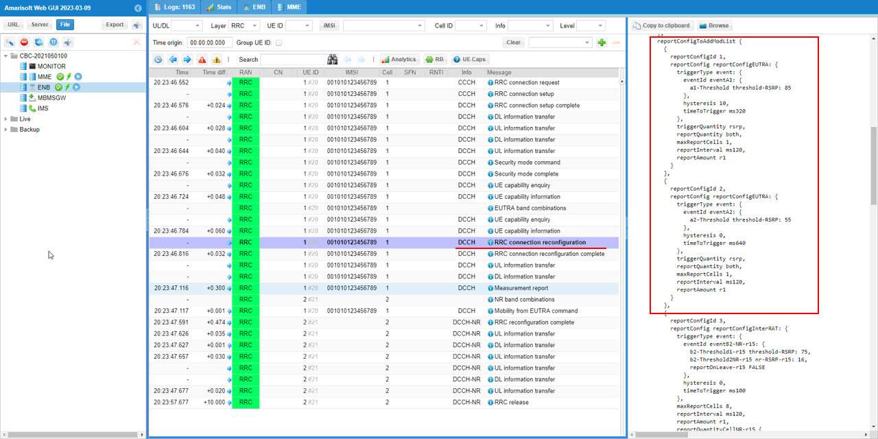
Then check reportConfigToAddModList and see if all the events are configured as intented. Here you see that event-a1 and a2 and b2 is configured.
reportConfigId 1 is a reportConfigEUTRA carrying eventA1 with a1-Threshold threshold-RSRP: 85, hysteresis 10 and timeToTrigger ms320. reportConfigId 2 is a reportConfigEUTRA carrying eventA2 with a2-Threshold threshold-RSRP: 55, hysteresis 0 and timeToTrigger ms640. Both use triggerQuantity rsrp, reportQuantity both, maxReportCells 1, reportInterval ms120 and reportAmount r1.
reportConfigId 3 is a reportConfigInterRAT carrying eventB2-NR-r15, which is the event that matters for this test. It has b2-Threshold1-r15 threshold-RSRP: 75, b2-Threshold2NR-r15 nr-RSRP-r15: 16, reportOnLeave-r15 FALSE, hysteresis 0, timeToTrigger ms100 and maxReportCells 8.
You may want to compare these values with the meas_config_desc set earlier in the configuration, because the message carries the encoded RSRP index rather than the dBm value. The a1 threshold 85 corresponds to the configured a1_rsrp of -55, the a2 threshold 55 corresponds to a2_rsrp -85, and the b2-Threshold1 of 75 corresponds to b2_threshold1_rsrp -65. The b2-Threshold2NR of 16 corresponds to b2_threshold2_rsrp -140 on the NR scale. Checking this correspondence is the reliable way to confirm that the thresholds you configured are the ones actually signaled to the UE.
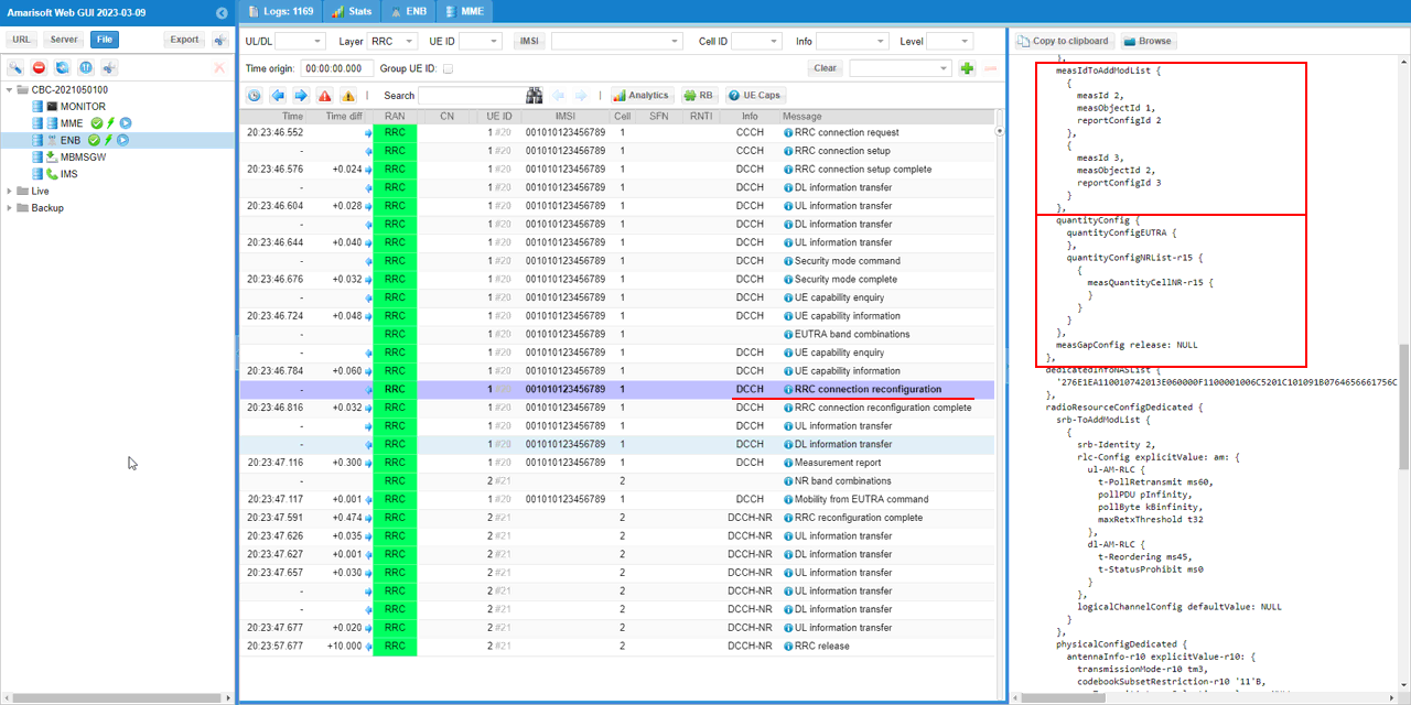
Now check out measIDToAddModList and see if the measurement conditions are configured as intended. Here you see a2 measurement is registered as measId 2 and b2 measurement is registered as measId3.
Each entry of this list is what actually binds a measurement object to a report configuration. measId 2 links measObjectId 1 with reportConfigId 2, which is the LTE frequency measured against the A2 event, and measId 3 links measObjectId 2 with reportConfigId 3, which is the NR frequency measured against the B2 event. The measId 3 shown here is the value you should expect to see in the measurement report that triggers the handover.
Below the list, quantityConfig contains quantityConfigEUTRA and quantityConfigNRList-r15 with measQuantityCellNR-r15, which set the filtering applied to the LTE and NR measurements. In this message measGapConfig is shown as release: NULL.
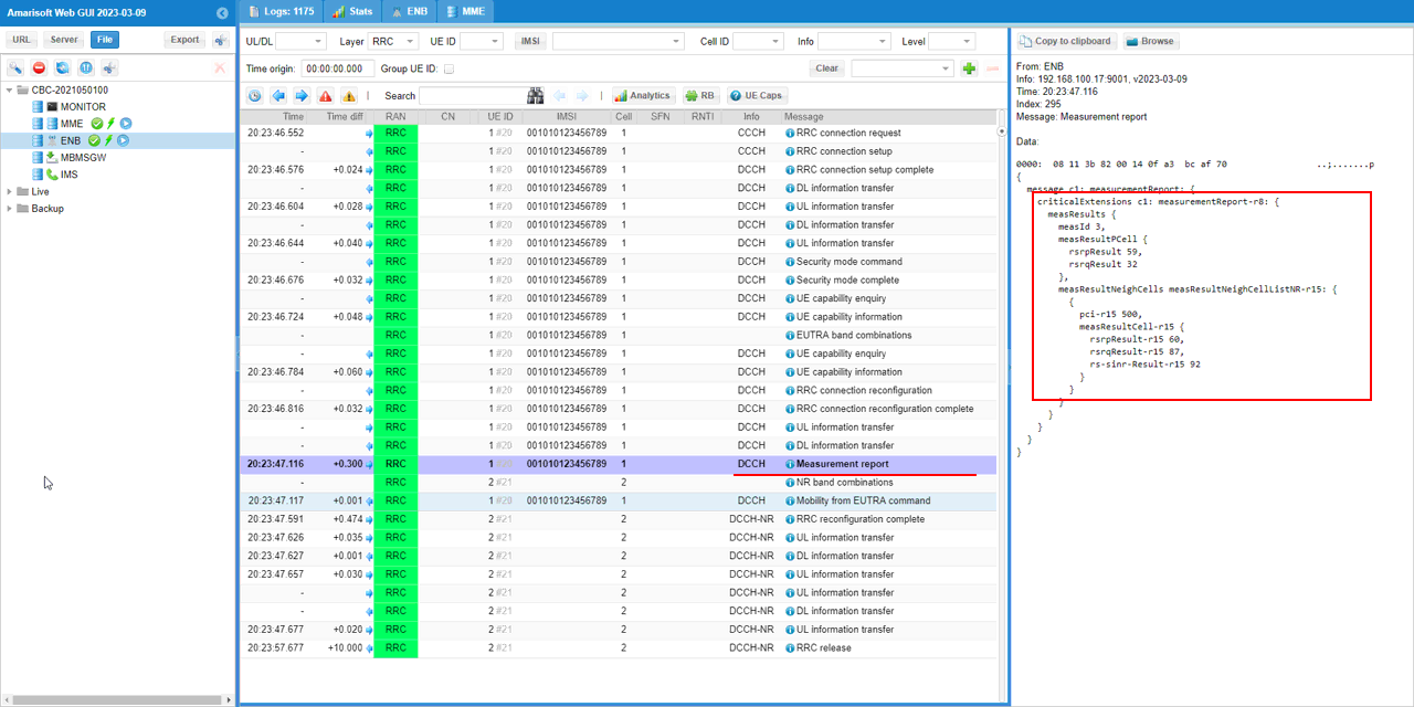
UE send measurementReport with the reception of b2 event (Measurement for NR cell)
The measResults block reports measId 3, which is the B2 measurement registered in the previous step, so this confirms the report was raised by the inter-RAT event and not by the A1 or A2 event.
measResultPCell gives the serving LTE cell with rsrpResult 59 and rsrqResult 32, and measResultNeighCells reports a measResultNeighCellListNR-r15 entry with pci-r15 500, rsrpResult-r15 60, rsrqResult-r15 87 and rs-sinr-Result-r15 92. The pci-r15 500 matches the NR cell that the UEsim detected earlier with the cells command, so the UE is reporting the intended target.
This message is the trigger for everything that follows. Because ho_from_meas was set to true, the eNB only starts the handover preparation after receiving this report, so if you do not see this message you should go back and tweak the cell power rather than looking for a problem in the handover procedure itself.
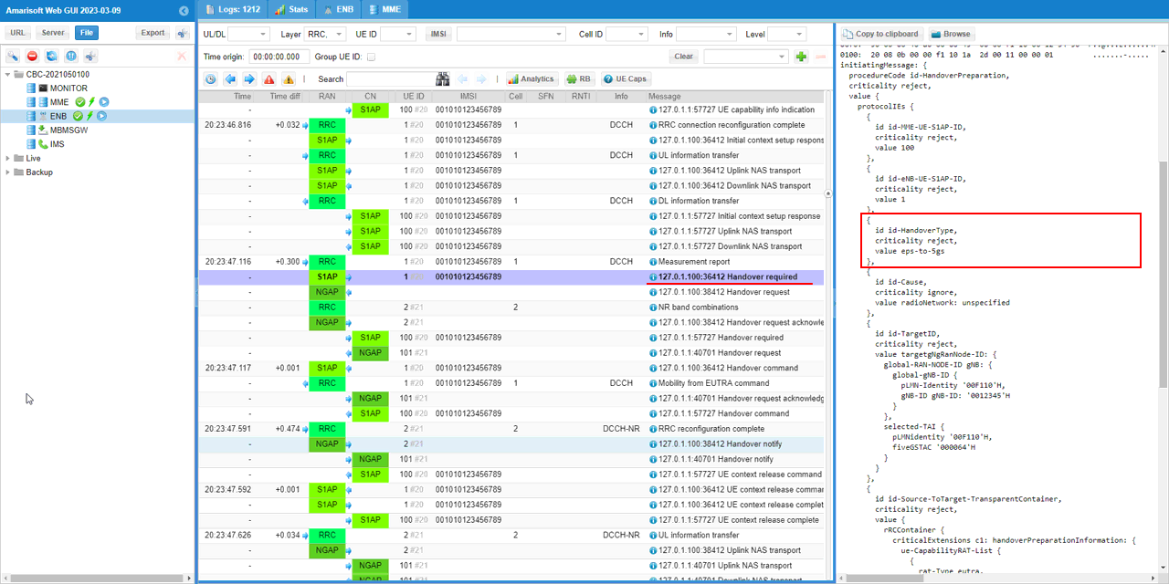
eNB send "Handover required" message for 'eps-to-5gs' to core network.
This is an S1AP message with procedureCode id-HandoverPreparation. The id-HandoverType is set to eps-to-5gs, which is the value that makes this an inter-system handover towards 5GS rather than an ordinary intra-LTE handover, and it is only possible because eps_5gs_interworking was set to "with_n26" on the corenetwork.
The id-TargetID identifies where the UE should go. It carries a targetgNgRanNode-ID with a global-gNB-ID of pLMN-Identity '00F110'H and gNB-ID '0012345'H, which is the gNB_ID 0x12345 seen earlier in the cell phy output, and a selected-TAI with fiveGSTAC '000064'H, which is the tac 100 configured in the NR cell. The id-Cause is radioNetwork: unspecified, and the message also carries a Source-ToTarget-TransparentContainer holding the handoverPreparationInformation with the UE capability list.
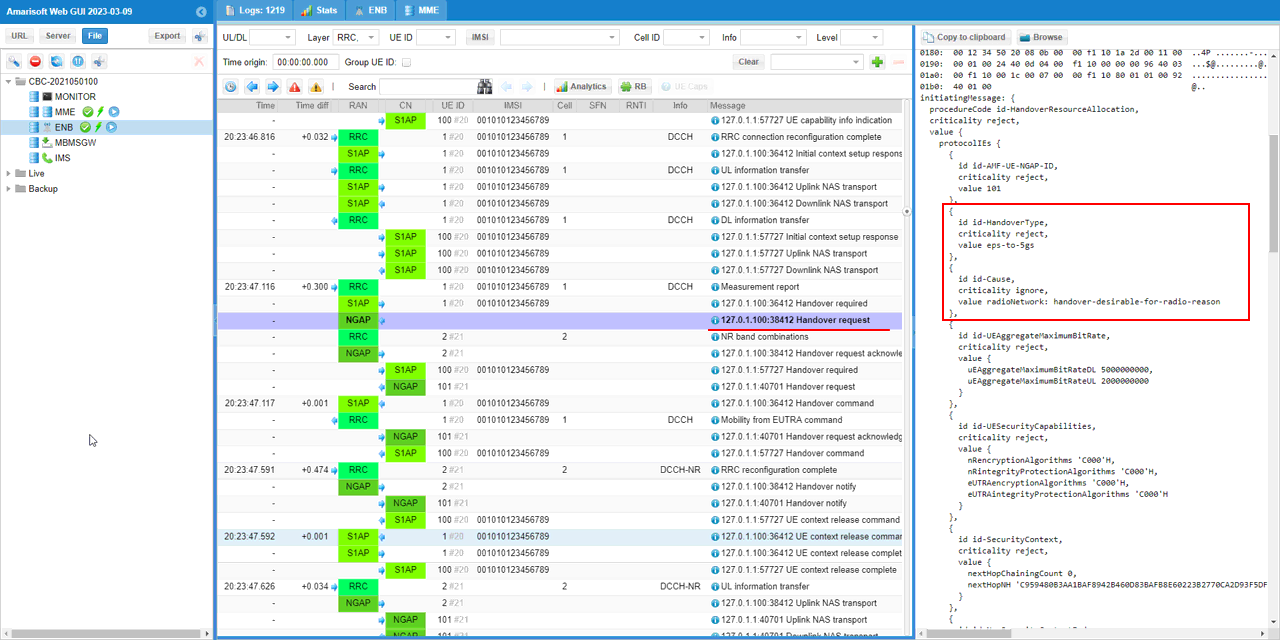
Corenetwork send "Handover Request" message to eNB.
This one is carried over NGAP rather than S1AP, as shown by the NGAP tag in the RAN column, because it is addressed to the NR side of the Callbox. The procedureCode is id-HandoverResourceAllocation and the id-HandoverType is again eps-to-5gs.
The id-Cause is radioNetwork: handover-desirable-for-radio-reason, which reflects that the handover was requested because of the radio measurement. The message also carries the resources and context the target needs, with id-UEAggregateMaximumBitRate of 5000000000 DL and 2000000000 UL, id-UESecurityCapabilities listing the nR and eUTRA encryption and integrity algorithms, and id-SecurityContext with nextHopChainingCount 0 and the nextHopNH value.
eNB aknowledge with 'Handover request acknowledge' message.
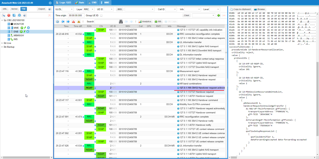
This is the successfulOutcome of the same id-HandoverResourceAllocation procedure, so it confirms that the target admitted the UE. The important part is id-PDUSessionResourceAdmittedList, which shows pDUSessionID 1 being admitted, meaning the data session is carried over to the NR side rather than dropped.
Inside the handoverRequestAcknowledgeTransfer you can see the tunnels being set up. dL-NGU-UP-TNLInformation gives a gTPTunnel with transportLayerAddress '7F000101'H and gTP-TEID '3B54380C'H, and dLForwardingUP-TNLInformation gives a second tunnel with gTP-TEID '75D56024'H. The qosFlowSetupResponseList shows qosFlowIdentifier 1 with dataForwardingAccepted set to data-forwarding-accepted, so the downlink data of the source side can be forwarded to the target during the switch.
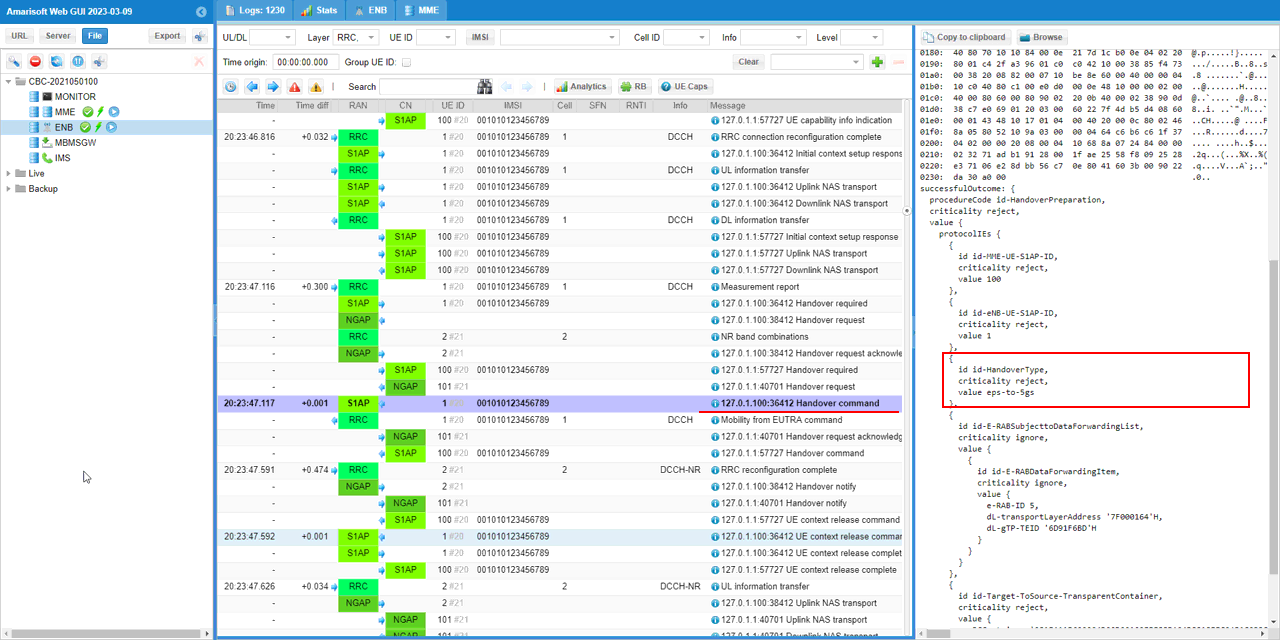
eNB recieves 'Handover command' message for 'eps-to-5gs' from the core network.
This is the successfulOutcome of the id-HandoverPreparation procedure that was started by the Handover required message, so it closes the preparation phase on the source side. The id-HandoverType is eps-to-5gs as before.
The id-E-RABSubjecttoDataForwardingList holds an E-RABDataForwardingItem with e-RAB-ID 5, dl-transportLayerAddress '7F000164'H and dl-gTP-TEID '6D91F6BD'H, which tells the eNB where to forward the downlink data it still holds. The message also carries the Target-ToSource-TransparentContainer, which contains the NR configuration produced by the target and which the eNB passes on to the UE in the next message.
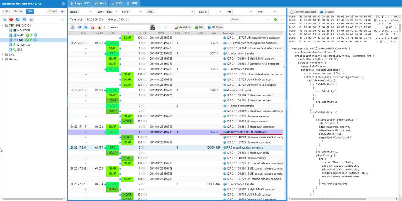
Then eNB send Mobility from EUTRA message to UE to trigger InterRAT (LTE to NR) handover.
The message is a mobilityFromEUTRACommand with cs-FallbackIndicator FALSE and purpose handover, and the targetRAT-Type is set to nr. This is the point where the UE is actually told to leave the LTE cell.
The targetRAT-MessageContainer carries a complete NR rrcReconfiguration, which is the container that was delivered from the target in the previous message. Inside it, radioBearerConfig sets up srb-Identity 1 and srb-Identity 2 and a drb-ToAddModList entry with drb-Identity 1. The cnAssociation is an sdap-Config with pdu-Session 1, sdap-HeaderDL absent, sdap-HeaderUL present and defaultDRB TRUE, which is the SDAP layer that only exists in NR and is a clear sign the UE is being reconfigured for a 5GS session.
The pdcp-Config of the DRB uses discardTimer infinity, pdcp-SN-SizeUL and pdcp-SN-SizeDL of len18bits, headerCompression notUsed and statusReportRequired true, with t-Reordering ms3000.
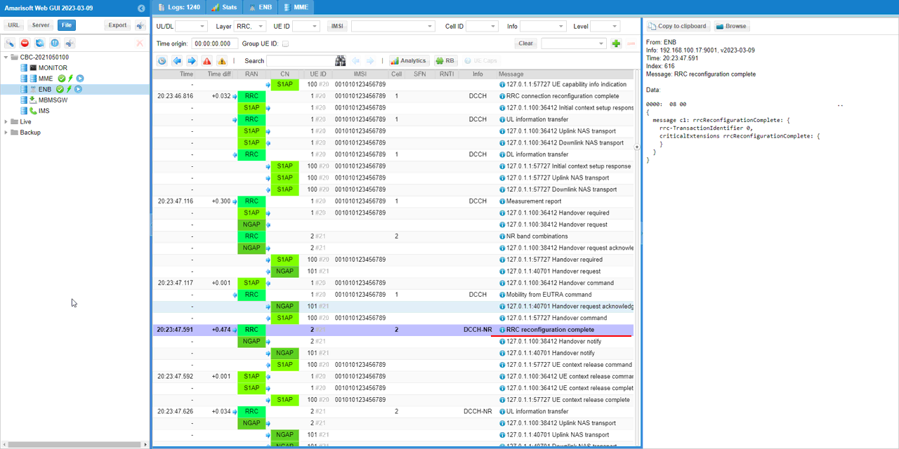
UE respond with RRC Reconfiguration complete when the configuration in Mobility from EUTRA command is acceptable.
The most useful detail here is not in the message body but in the columns of the log list. This message is shown on DCCH-NR and on cell 2, while every message up to the Mobility from EUTRA command was on DCCH and cell 1. That change of radio bearer and cell is the proof that the UE has actually moved to the NR cell and is now talking to it.
The timestamp is 20:23:47.591 with a time diff of +0.474 from the previous message, so the switch itself took less than half a second. The message content is simply rrcReconfigurationComplete with rrc-TransactionIdentifier 0 and an empty criticalExtensions, since it only needs to confirm that the configuration was accepted.
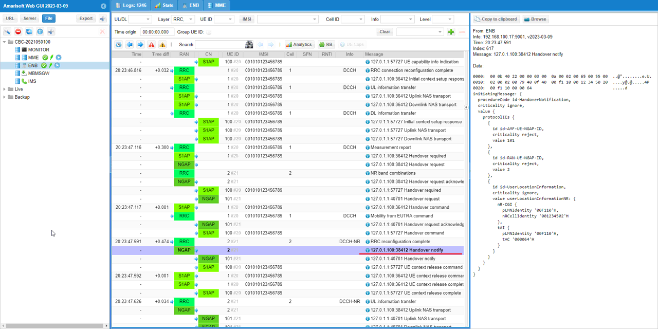
eNB sends Handover notify message to core network indicating that Handover is being processed.
This is an NGAP message with procedureCode id-HandoverNotification and it is sent from the NR side, since it is the target that tells the core network the UE has arrived.
The id-UserLocationInformation is the part worth checking, because it is expressed as userLocationInformationNR. It carries an nR-CGI with pLMNidentity '00F110'H and nRCellIdentity '001234502'H, and a tAI with tAC '000064'H. The NR cell identity here is built from the gNB_ID 0x12345 and the cell, so this message confirms that the core network now considers the UE to be located on the NR cell rather than the LTE one.
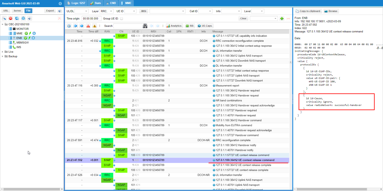
Core network notifies gNB of 'success handover' via UE context release command message.
The id-Cause of this message is radioNetwork: successful-handover, which is the explicit confirmation that the handover is regarded as completed rather than failed. This is the single field to look at if you only want a yes or no answer on whether the handover succeeded.
The procedureCode is id-UEContextRelease and the id-UE-S1AP-IDs carries a uE-S1AP-ID-pair with mME-UE-S1AP-ID 100 and eNB-UE-S1AP-ID 1. These are the same identifiers used in the Handover required message at the start, so this release refers to the LTE context that is no longer needed now that the UE has moved.
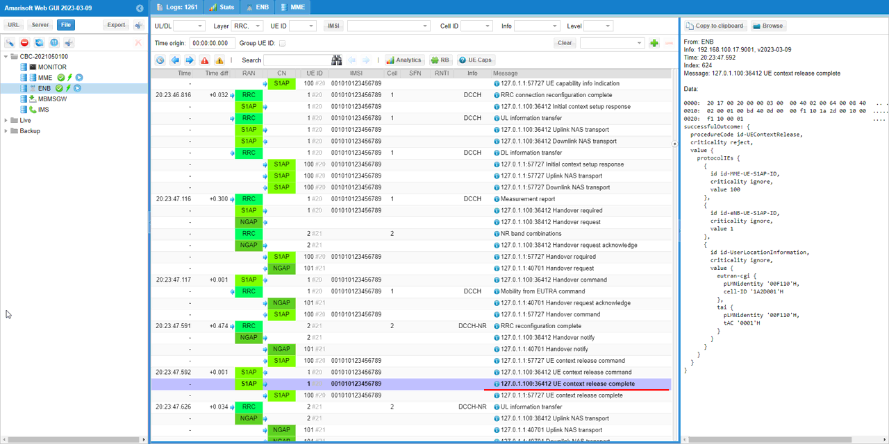
eNB replies to core network with UE context release complete message.
This is the successfulOutcome of id-UEContextRelease and it completes the release of the source side resources. It repeats id-MME-UE-S1AP-ID 100 and id-eNB-UE-S1AP-ID 1.
The id-UserLocationInformation here is an eutran-cgi with pLMNidentity '00F110'H and cell-ID '1A2D001'H, together with a tai carrying tAC '0001'H. Compare this with the Handover notify message, where the location was reported as an nR-CGI. This message reports the LTE location because it is the source side reporting where the UE was before it left.
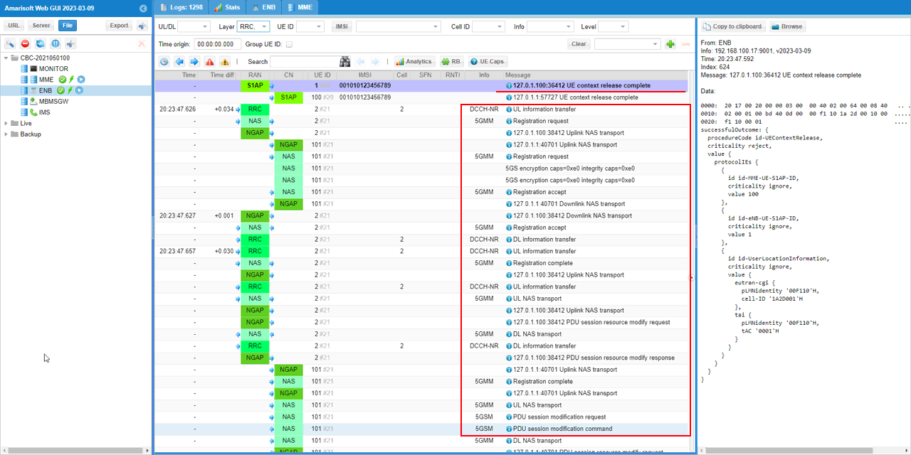
Once handover is complete and cell is switched to the destination cell (NR cell), UE goes through registration process for the target cell.
This registration runs entirely on the 5GS NAS. There is a Registration request on 5GMM carried in an Uplink NAS transport, then a Registration accept in a Downlink NAS transport, and finally a Registration complete. This is the procedure that n1_support: true in the UEsim configuration made possible, since a UE without N1 mode support could not run 5GMM at all.
The line showing 5GS encryption caps=0xe0 integrity caps=0xe0 is the security capability the UE declares for the 5GS side, which is separate from the EPS capability it used on the LTE cell.
After the registration, the log continues with the session being adjusted for the new system. There is a PDU session resource modify request and a matching PDU session resource modify response on NGAP, and a PDU session modification request and PDU session modification command on 5GSM. These follow the registration because the data session admitted during the handover has to be brought fully under 5GS control.
All of these messages are carried on DCCH-NR and on cell 2, which is consistent with the RRC reconfiguration complete seen earlier and confirms the UE is operating entirely on the NR cell from this point.
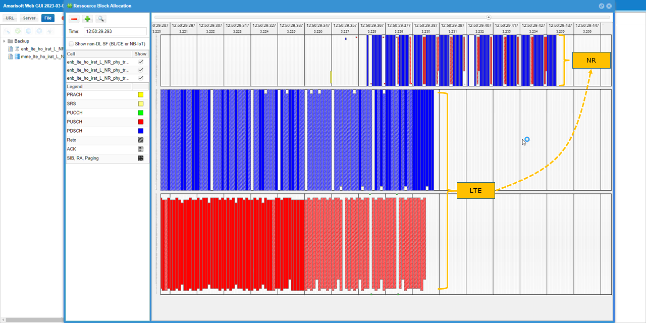
You can confirm on the result of handover (cell switch) happening in PHY layer by looking into RB map.
The view is split into panes and annotated with yellow LTE and NR labels joined by a dashed arrow, which shows the direction of the switch. The middle and bottom panes are the LTE cell and the top pane is the NR cell.
In the LTE panes the allocation is dense on the left and then stops. The middle pane is filled with blue, which is PDSCH according to the legend, and the bottom pane is filled with red, which is PUSCH. Both stop at about 12:50:29.357. In the NR pane the opposite happens, with blue and red allocation only starting at around 12:50:29.367 and continuing to the right.
The fact that the LTE activity ends and the NR activity begins at nearly the same instant, with only a short gap in between, is the PHY level confirmation of the handover. This continuous filling of the RB map in both directions is also the reason force_dl_schedule and force_full_bsr were enabled in the cell configuration, because without them the map would be mostly empty and the moment of the switch would be much harder to see.
RRC / NAS Signaling
Here I will just list required message from callbox and I haven't put the required messages from UE side. For the messages from UE, refer to the log analysis and check further with the sample log linked above.
This is the RrcReconfiguration sent by gNB to configure measurement and handover. (
RrcConnectionReconfiguration - Measurement Configuration
{
message c1: rrcConnectionReconfiguration: {
rrc-TransactionIdentifier 0,
criticalExtensions c1: rrcConnectionReconfiguration-r8: {
measConfig {
measObjectToAddModList {
{
measObjectId 1,
measObject measObjectEUTRA: {
carrierFreq 300,
allowedMeasBandwidth mbw100,
presenceAntennaPort1 TRUE,
neighCellConfig '01'B
}
},
{
measObjectId 2,
measObject measObjectNR-r15: {
carrierFreq-r15 632544,
rs-ConfigSSB-r15 {
measTimingConfig-r15 {
periodicityAndOffset-r15 sf20-r15: 0,
ssb-Duration-r15 sf1
},
subcarrierSpacingSSB-r15 kHz30
},
quantityConfigSet-r15 1,
bandNR-r15 setup: 78
}
}
},
reportConfigToAddModList {
{
reportConfigId 1,
reportConfig reportConfigEUTRA: {
triggerType event: {
eventId eventA1: {
a1-Threshold threshold-RSRP: 85
},
hysteresis 10,
timeToTrigger ms320
},
triggerQuantity rsrp,
reportQuantity both,
maxReportCells 1,
reportInterval ms120,
reportAmount r1
}
},
{
reportConfigId 2,
reportConfig reportConfigEUTRA: {
triggerType event: {
eventId eventA2: {
a2-Threshold threshold-RSRP: 55
},
hysteresis 0,
timeToTrigger ms640
},
triggerQuantity rsrp,
reportQuantity both,
maxReportCells 1,
reportInterval ms120,
reportAmount r1
}
},
{
reportConfigId 3,
reportConfig reportConfigInterRAT: {
triggerType event: {
eventId eventB2-NR-r15: {
b2-Threshold1-r15 threshold-RSRP: 75,
b2-Threshold2NR-r15 nr-RSRP-r15: 16,
reportOnLeave-r15 FALSE
},
hysteresis 0,
timeToTrigger ms100
},
maxReportCells 8,
reportInterval ms120,
reportAmount r1,
reportQuantityCellNR-r15 {
ss-rsrp TRUE,
ss-rsrq TRUE,
ss-sinr TRUE
}
}
}
},
measIdToAddModList {
{
measId 2,
measObjectId 1,
reportConfigId 2
},
{
measId 3,
measObjectId 2,
reportConfigId 3
}
},
quantityConfig {
quantityConfigEUTRA {
},
quantityConfigNRList-r15 {
{
measQuantityCellNR-r15 {
}
}
}
},
measGapConfig release: NULL
},
dedicatedInfoNASList {
'27A585B8BD010742013E06000.......'H
},
radioResourceConfigDedicated {
srb-ToAddModList {
{
srb-Identity 2,
rlc-Config explicitValue: am: {
ul-AM-RLC {
t-PollRetransmit ms60,
pollPDU pInfinity,
pollByte kBinfinity,
maxRetxThreshold t32
},
dl-AM-RLC {
t-Reordering ms45,
t-StatusProhibit ms0
}
},
logicalChannelConfig defaultValue: NULL
}
},
physicalConfigDedicated {
antennaInfo-r10 explicitValue-r10: {
transmissionMode-r10 tm3,
codebookSubsetRestriction-r10 '11'B,
ue-TransmitAntennaSelection release: NULL
},
cqi-ReportConfig-r10 {
nomPDSCH-RS-EPRE-Offset 0,
cqi-ReportPeriodic-r10 setup: {
cqi-PUCCH-ResourceIndex-r10 0,
cqi-pmi-ConfigIndex 38,
cqi-FormatIndicatorPeriodic-r10 widebandCQI-r10: {
},
ri-ConfigIndex 483,
simultaneousAckNackAndCQI TRUE
}
}
},
drb-ToAddModList-r15 {
{
eps-BearerIdentity 5,
drb-Identity 1,
rlc-Config am: {
ul-AM-RLC {
t-PollRetransmit ms80,
pollPDU p64,
pollByte kB125,
maxRetxThreshold t32
},
dl-AM-RLC {
t-Reordering ms35,
t-StatusProhibit ms10
}
},
logicalChannelIdentity 3,
logicalChannelConfig {
ul-SpecificParameters {
priority 15,
prioritisedBitRate kBps8,
bucketSizeDuration ms100,
logicalChannelGroup 3
}
}
}
}
},
nonCriticalExtension {
nonCriticalExtension {
nonCriticalExtension {
nonCriticalExtension {
nonCriticalExtension {
nonCriticalExtension {
nonCriticalExtension {
nonCriticalExtension {
nr-RadioBearerConfig1-r15 {
drb-ToAddModList {
{
cnAssociation eps-BearerIdentity: 5,
drb-Identity 1,
pdcp-Config {
drb {
discardTimer infinity,
pdcp-SN-SizeUL len18bits,
pdcp-SN-SizeDL len18bits,
headerCompression notUsed: NULL,
statusReportRequired true
},
t-Reordering ms3000
}
}
},
securityConfig {
securityAlgorithmConfig {
cipheringAlgorithm nea0
},
keyToUse master
}
Mobility From Utra Command - Handover
{
message c1: mobilityFromEUTRACommand: {
rrc-TransactionIdentifier 0,
criticalExtensions c1: mobilityFromEUTRACommand-r9: {
cs-FallbackIndicator FALSE,
purpose handover: {
targetRAT-Type nr,
targetRAT-MessageContainer {
rrc-TransactionIdentifier 0,
criticalExtensions rrcReconfiguration: {
radioBearerConfig {
srb-ToAddModList {
{
srb-Identity 1
},
{
srb-Identity 2
}
},
drb-ToAddModList {
{
cnAssociation sdap-Config: {
pdu-Session 1,
sdap-HeaderDL absent,
sdap-HeaderUL present,
defaultDRB TRUE,
mappedQoS-FlowsToAdd {
1
}
},
drb-Identity 1,
pdcp-Config {
drb {
discardTimer infinity,
pdcp-SN-SizeUL len18bits,
pdcp-SN-SizeDL len18bits,
headerCompression notUsed: NULL,
statusReportRequired true
},
t-Reordering ms3000
}
}
},
securityConfig {
securityAlgorithmConfig {
cipheringAlgorithm nea0,
integrityProtAlgorithm nia2
},
keyToUse master
}
},
nonCriticalExtension {
masterCellGroup {
cellGroupId 0,
rlc-BearerToAddModList {
{
logicalChannelIdentity 4,
servedRadioBearer drb-Identity: 1,
rlc-Config am: {
ul-AM-RLC {
sn-FieldLength size18,
t-PollRetransmit ms80,
pollPDU p64,
pollByte kB125,
maxRetxThreshold t4
},
dl-AM-RLC {
sn-FieldLength size18,
t-Reassembly ms80,
t-StatusProhibit ms10
}
},
mac-LogicalChannelConfig {
ul-SpecificParameters {
priority 13,
prioritisedBitRate kBps8,
bucketSizeDuration ms100,
logicalChannelGroup 7,
schedulingRequestID 0,
logicalChannelSR-Mask FALSE,
logicalChannelSR-DelayTimerApplied FALSE
}
}
},
{
logicalChannelIdentity 1,
servedRadioBearer srb-Identity: 1,
rlc-Config am: {
ul-AM-RLC {
sn-FieldLength size12,
t-PollRetransmit ms45,
pollPDU infinity,
pollByte infinity,
maxRetxThreshold t8
},
dl-AM-RLC {
sn-FieldLength size12,
t-Reassembly ms35,
t-StatusProhibit ms0
}
},
mac-LogicalChannelConfig {
ul-SpecificParameters {
priority 1,
prioritisedBitRate infinity,
bucketSizeDuration ms5,
logicalChannelGroup 0,
schedulingRequestID 0,
logicalChannelSR-Mask FALSE,
logicalChannelSR-DelayTimerApplied FALSE
}
}
},
{
logicalChannelIdentity 2,
servedRadioBearer srb-Identity: 2,
rlc-Config am: {
ul-AM-RLC {
sn-FieldLength size12,
t-PollRetransmit ms45,
pollPDU infinity,
pollByte infinity,
maxRetxThreshold t8
},
dl-AM-RLC {
sn-FieldLength size12,
t-Reassembly ms35,
t-StatusProhibit ms0
}
},
mac-LogicalChannelConfig {
ul-SpecificParameters {
priority 3,
prioritisedBitRate infinity,
bucketSizeDuration ms5,
logicalChannelGroup 0,
schedulingRequestID 0,
logicalChannelSR-Mask FALSE,
logicalChannelSR-DelayTimerApplied FALSE
}
}
}
},
mac-CellGroupConfig {
schedulingRequestConfig {
schedulingRequestToAddModList {
{
schedulingRequestId 0,
sr-TransMax n64
}
}
},
bsr-Config {
periodicBSR-Timer sf20,
retxBSR-Timer sf320
},
tag-Config {
tag-ToAddModList {
{
tag-Id 0,
timeAlignmentTimer infinity
}
}
},
phr-Config setup: {
phr-PeriodicTimer sf500,
phr-ProhibitTimer sf200,
phr-Tx-PowerFactorChange dB3,
multiplePHR FALSE,
dummy FALSE,
phr-Type2OtherCell FALSE,
phr-ModeOtherCG real
},
skipUplinkTxDynamic FALSE,
dataInactivityTimer release: NULL
},
physicalCellGroupConfig {
pdsch-HARQ-ACK-Codebook dynamic
},
spCellConfig {
reconfigurationWithSync {
spCellConfigCommon {
physCellId 500,
downlinkConfigCommon {
frequencyInfoDL {
absoluteFrequencySSB 632544,
frequencyBandList {
78
},
absoluteFrequencyPointA 632016,
scs-SpecificCarrierList {
{
offsetToCarrier 0,
subcarrierSpacing kHz30,
carrierBandwidth 51
}
}
},
initialDownlinkBWP {
genericParameters {
locationAndBandwidth 13750,
subcarrierSpacing kHz30
},
pdcch-ConfigCommon setup: {
controlResourceSetZero 10,
searchSpaceZero 0,
commonSearchSpaceList {
{
searchSpaceId 1,
controlResourceSetId 0,
monitoringSlotPeriodicityAndOffset sl1: NULL,
monitoringSymbolsWithinSlot '10000000000000'B,
nrofCandidates {
aggregationLevel1 n0,
aggregationLevel2 n0,
aggregationLevel4 n4,
aggregationLevel8 n0,
aggregationLevel16 n0
},
searchSpaceType common: {
dci-Format0-0-AndFormat1-0 {
}
}
}
},
searchSpaceSIB1 0,
searchSpaceOtherSystemInformation 1,
pagingSearchSpace 1,
ra-SearchSpace 1
},
pdsch-ConfigCommon setup: {
pdsch-TimeDomainAllocationList {
{
mappingType typeA,
startSymbolAndLength 40
},
{
mappingType typeA,
startSymbolAndLength 57
}
}
}
}
},
uplinkConfigCommon {
frequencyInfoUL {
scs-SpecificCarrierList {
{
offsetToCarrier 0,
subcarrierSpacing kHz30,
carrierBandwidth 51
}
}
},
initialUplinkBWP {
genericParameters {
locationAndBandwidth 13750,
subcarrierSpacing kHz30
},
rach-ConfigCommon setup: {
rach-ConfigGeneric {
prach-ConfigurationIndex 160,
msg1-FDM one,
msg1-FrequencyStart 3,
zeroCorrelationZoneConfig 15,
preambleReceivedTargetPower -110,
preambleTransMax n7,
powerRampingStep dB4,
ra-ResponseWindow sl20
},
ssb-perRACH-OccasionAndCB-PreamblesPerSSB one: n8,
ra-ContentionResolutionTimer sf64,
prach-RootSequenceIndex l139: 1,
msg1-SubcarrierSpacing kHz30,
restrictedSetConfig unrestrictedSet
},
pusch-ConfigCommon setup: {
pusch-TimeDomainAllocationList {
{
k2 7,
mappingType typeA,
startSymbolAndLength 27
},
{
k2 4,
mappingType typeA,
startSymbolAndLength 27
},
{
k2 5,
mappingType typeA,
startSymbolAndLength 27
}
},
p0-NominalWithGrant -84
},
pucch-ConfigCommon setup: {
pucch-ResourceCommon 11,
pucch-GroupHopping neither,
p0-nominal -90
}
},
dummy ms500
},
ssb-PositionsInBurst mediumBitmap: '80'H,
ssb-periodicityServingCell ms20,
dmrs-TypeA-Position pos2,
ssbSubcarrierSpacing kHz30,
tdd-UL-DL-ConfigurationCommon {
referenceSubcarrierSpacing kHz30,
pattern1 {
dl-UL-TransmissionPeriodicity ms5,
nrofDownlinkSlots 7,
nrofDownlinkSymbols 6,
nrofUplinkSlots 2,
nrofUplinkSymbols 4
}
},
ss-PBCH-BlockPower -56
},
newUE-Identity 17921,
t304 ms1000,
smtc {
periodicityAndOffset sf20: 0,
duration sf1
}
},
spCellConfigDedicated {
initialDownlinkBWP {
pdcch-Config setup: {
controlResourceSetToAddModList {
{
controlResourceSetId 2,
frequencyDomainResources '111111110000000000000000000000000000000000000'B,
duration 1,
cce-REG-MappingType nonInterleaved: NULL,
precoderGranularity sameAsREG-bundle
}
},
searchSpacesToAddModList {
{
searchSpaceId 2,
controlResourceSetId 2,
monitoringSlotPeriodicityAndOffset sl1: NULL,
monitoringSymbolsWithinSlot '10000000000000'B,
nrofCandidates {
aggregationLevel1 n0,
aggregationLevel2 n2,
aggregationLevel4 n1,
aggregationLevel8 n0,
aggregationLevel16 n0
},
searchSpaceType ue-Specific: {
dci-Formats formats0-1-And-1-1
}
}
}
},
pdsch-Config setup: {
dmrs-DownlinkForPDSCH-MappingTypeA setup: {
dmrs-AdditionalPosition pos1
},
tci-StatesToAddModList {
{
tci-StateId 0,
qcl-Type1 {
referenceSignal ssb: 0,
qcl-Type typeD
}
}
},
resourceAllocation resourceAllocationType1,
rbg-Size config1,
mcs-Table qam256,
prb-BundlingType staticBundling: {
bundleSize wideband
},
zp-CSI-RS-ResourceToAddModList {
{
zp-CSI-RS-ResourceId 0,
resourceMapping {
frequencyDomainAllocation row4: '100'B,
nrofPorts p4,
firstOFDMSymbolInTimeDomain 8,
cdm-Type fd-CDM2,
density one: NULL,
freqBand {
startingRB 0,
nrofRBs 52
}
},
periodicityAndOffset slots80: 1
}
},
p-ZP-CSI-RS-ResourceSet setup: {
zp-CSI-RS-ResourceSetId 0,
zp-CSI-RS-ResourceIdList {
0
}
}
}
},
firstActiveDownlinkBWP-Id 0,
uplinkConfig {
initialUplinkBWP {
pucch-Config setup: {
resourceSetToAddModList {
{
pucch-ResourceSetId 0,
resourceList {
0,
1,
2,
3,
4,
5,
6,
7
}
},
{
pucch-ResourceSetId 1,
resourceList {
8,
9,
10,
11
}
}
},
resourceToAddModList {
{
pucch-ResourceId 0,
startingPRB 50,
intraSlotFrequencyHopping enabled,
secondHopPRB 0,
format format1: {
initialCyclicShift 1,
nrofSymbols 14,
startingSymbolIndex 0,
timeDomainOCC 0
}
},
{
pucch-ResourceId 1,
startingPRB 50,
intraSlotFrequencyHopping enabled,
secondHopPRB 0,
format format1: {
initialCyclicShift 5,
nrofSymbols 14,
startingSymbolIndex 0,
timeDomainOCC 0
}
},
{
pucch-ResourceId 2,
startingPRB 50,
intraSlotFrequencyHopping enabled,
secondHopPRB 0,
format format1: {
initialCyclicShift 9,
nrofSymbols 14,
startingSymbolIndex 0,
timeDomainOCC 0
}
},
{
pucch-ResourceId 3,
startingPRB 50,
intraSlotFrequencyHopping enabled,
secondHopPRB 0,
format format1: {
initialCyclicShift 1,
nrofSymbols 14,
startingSymbolIndex 0,
timeDomainOCC 1
}
},
{
pucch-ResourceId 4,
startingPRB 50,
intraSlotFrequencyHopping enabled,
secondHopPRB 0,
format format1: {
initialCyclicShift 5,
nrofSymbols 14,
startingSymbolIndex 0,
timeDomainOCC 1
}
},
{
pucch-ResourceId 5,
startingPRB 50,
intraSlotFrequencyHopping enabled,
secondHopPRB 0,
format format1: {
initialCyclicShift 9,
nrofSymbols 14,
startingSymbolIndex 0,
timeDomainOCC 1
}
},
{
pucch-ResourceId 6,
startingPRB 50,
intraSlotFrequencyHopping enabled,
secondHopPRB 0,
format format1: {
initialCyclicShift 1,
nrofSymbols 14,
startingSymbolIndex 0,
timeDomainOCC 2
}
},
{
pucch-ResourceId 7,
startingPRB 50,
intraSlotFrequencyHopping enabled,
secondHopPRB 0,
format format1: {
initialCyclicShift 5,
nrofSymbols 14,
startingSymbolIndex 0,
timeDomainOCC 2
}
},
{
pucch-ResourceId 8,
startingPRB 1,
intraSlotFrequencyHopping enabled,
secondHopPRB 49,
format format2: {
nrofPRBs 1,
nrofSymbols 2,
startingSymbolIndex 0
}
},
{
pucch-ResourceId 9,
startingPRB 1,
intraSlotFrequencyHopping enabled,
secondHopPRB 49,
format format2: {
nrofPRBs 1,
nrofSymbols 2,
startingSymbolIndex 2
}
},
{
pucch-ResourceId 10,
startingPRB 1,
intraSlotFrequencyHopping enabled,
secondHopPRB 49,
format format2: {
nrofPRBs 1,
nrofSymbols 2,
startingSymbolIndex 4
}
},
{
pucch-ResourceId 11,
startingPRB 1,
intraSlotFrequencyHopping enabled,
secondHopPRB 49,
format format2: {
nrofPRBs 1,
nrofSymbols 2,
startingSymbolIndex 6
}
},
{
pucch-ResourceId 12,
startingPRB 50,
intraSlotFrequencyHopping enabled,
secondHopPRB 0,
format format1: {
initialCyclicShift 9,
nrofSymbols 14,
startingSymbolIndex 0,
timeDomainOCC 2
}
},
{
pucch-ResourceId 13,
startingPRB 1,
intraSlotFrequencyHopping enabled,
secondHopPRB 49,
format format2: {
nrofPRBs 1,
nrofSymbols 2,
startingSymbolIndex 8
}
}
},
format1 setup: {
},
format2 setup: {
maxCodeRate zeroDot25
},
schedulingRequestResourceToAddModList {
{
schedulingRequestResourceId 1,
schedulingRequestID 0,
periodicityAndOffset sl40: 8,
resource 12
}
},
dl-DataToUL-ACK {
8,
7,
6,
5,
4,
12,
11
}
},
pusch-Config setup: {
txConfig codebook,
dmrs-UplinkForPUSCH-MappingTypeA setup: {
dmrs-AdditionalPosition pos1,
transformPrecodingDisabled {
}
},
pusch-PowerControl {
msg3-Alpha alpha1,
p0-AlphaSets {
{
p0-PUSCH-AlphaSetId 0,
p0 0,
alpha alpha1
}
},
pathlossReferenceRSToAddModList {
{
pusch-PathlossReferenceRS-Id 0,
referenceSignal ssb-Index: 0
}
},
sri-PUSCH-MappingToAddModList {
{
sri-PUSCH-PowerControlId 0,
sri-PUSCH-PathlossReferenceRS-Id 0,
sri-P0-PUSCH-AlphaSetId 0,
sri-PUSCH-ClosedLoopIndex i0
}
}
},
resourceAllocation resourceAllocationType1,
mcs-Table qam256,
mcs-TableTransformPrecoder qam256,
codebookSubset nonCoherent,
maxRank 1,
uci-OnPUSCH setup: {
betaOffsets semiStatic: {
betaOffsetACK-Index1 9,
betaOffsetACK-Index2 9,
betaOffsetACK-Index3 9,
betaOffsetCSI-Part1-Index1 7,
betaOffsetCSI-Part1-Index2 7,
betaOffsetCSI-Part2-Index1 7,
betaOffsetCSI-Part2-Index2 7
},
scaling f1
}
},
srs-Config setup: {
srs-ResourceSetToAddModList {
{
srs-ResourceSetId 0,
srs-ResourceIdList {
0
},
resourceType aperiodic: {
aperiodicSRS-ResourceTrigger 1,
slotOffset 7
},
usage codebook,
p0 -84,
pathlossReferenceRS ssb-Index: 0
}
},
srs-ResourceToAddModList {
{
srs-ResourceId 0,
nrofSRS-Ports port1,
transmissionComb n2: {
combOffset-n2 0,
cyclicShift-n2 0
},
resourceMapping {
startPosition 0,
nrofSymbols n1,
repetitionFactor n1
},
freqDomainPosition 0,
freqDomainShift 5,
freqHopping {
c-SRS 11,
b-SRS 3,
b-hop 0
},
groupOrSequenceHopping neither,
resourceType aperiodic: {
},
sequenceId 500
}
}
}
},
firstActiveUplinkBWP-Id 0,
pusch-ServingCellConfig setup: {
}
},
pdcch-ServingCellConfig setup: {
},
pdsch-ServingCellConfig setup: {
nrofHARQ-ProcessesForPDSCH n16,
maxMIMO-Layers 2
},
csi-MeasConfig setup: {
nzp-CSI-RS-ResourceToAddModList {
{
nzp-CSI-RS-ResourceId 0,
resourceMapping {
frequencyDomainAllocation other: '100000'B,
nrofPorts p2,
firstOFDMSymbolInTimeDomain 4,
cdm-Type fd-CDM2,
density one: NULL,
freqBand {
startingRB 0,
nrofRBs 52
}
},
powerControlOffset 0,
powerControlOffsetSS db0,
scramblingID 500,
periodicityAndOffset slots80: 1,
qcl-InfoPeriodicCSI-RS 0
},
{
nzp-CSI-RS-ResourceId 1,
resourceMapping {
frequencyDomainAllocation row1: '1'H,
nrofPorts p1,
firstOFDMSymbolInTimeDomain 4,
cdm-Type noCDM,
density three: NULL,
freqBand {
startingRB 0,
nrofRBs 52
}
},
powerControlOffset 0,
powerControlOffsetSS db0,
scramblingID 500,
periodicityAndOffset slots40: 11,
qcl-InfoPeriodicCSI-RS 0
},
{
nzp-CSI-RS-ResourceId 2,
resourceMapping {
frequencyDomainAllocation row1: '1'H,
nrofPorts p1,
firstOFDMSymbolInTimeDomain 8,
cdm-Type noCDM,
density three: NULL,
freqBand {
startingRB 0,
nrofRBs 52
}
},
powerControlOffset 0,
powerControlOffsetSS db0,
scramblingID 500,
periodicityAndOffset slots40: 11,
qcl-InfoPeriodicCSI-RS 0
},
{
nzp-CSI-RS-ResourceId 3,
resourceMapping {
frequencyDomainAllocation row1: '1'H,
nrofPorts p1,
firstOFDMSymbolInTimeDomain 4,
cdm-Type noCDM,
density three: NULL,
freqBand {
startingRB 0,
nrofRBs 52
}
},
powerControlOffset 0,
powerControlOffsetSS db0,
scramblingID 500,
periodicityAndOffset slots40: 12,
qcl-InfoPeriodicCSI-RS 0
},
{
nzp-CSI-RS-ResourceId 4,
resourceMapping {
frequencyDomainAllocation row1: '1'H,
nrofPorts p1,
firstOFDMSymbolInTimeDomain 8,
cdm-Type noCDM,
density three: NULL,
freqBand {
startingRB 0,
nrofRBs 52
}
},
powerControlOffset 0,
powerControlOffsetSS db0,
scramblingID 500,
periodicityAndOffset slots40: 12,
qcl-InfoPeriodicCSI-RS 0
}
},
nzp-CSI-RS-ResourceSetToAddModList {
{
nzp-CSI-ResourceSetId 0,
nzp-CSI-RS-Resources {
0
}
},
{
nzp-CSI-ResourceSetId 1,
nzp-CSI-RS-Resources {
1,
2,
3,
4
},
trs-Info true
}
},
csi-IM-ResourceToAddModList {
{
csi-IM-ResourceId 0,
csi-IM-ResourceElementPattern pattern1: {
subcarrierLocation-p1 s8,
symbolLocation-p1 8
},
freqBand {
startingRB 0,
nrofRBs 52
},
periodicityAndOffset slots80: 1
}
},
csi-IM-ResourceSetToAddModList {
{
csi-IM-ResourceSetId 0,
csi-IM-Resources {
0
}
}
},
csi-ResourceConfigToAddModList {
{
csi-ResourceConfigId 0,
csi-RS-ResourceSetList nzp-CSI-RS-SSB: {
nzp-CSI-RS-ResourceSetList {
0
}
},
bwp-Id 0,
resourceType periodic
},
{
csi-ResourceConfigId 1,
csi-RS-ResourceSetList csi-IM-ResourceSetList: {
0
},
bwp-Id 0,
resourceType periodic
},
{
csi-ResourceConfigId 2,
csi-RS-ResourceSetList nzp-CSI-RS-SSB: {
nzp-CSI-RS-ResourceSetList {
1
}
},
bwp-Id 0,
resourceType periodic
}
},
csi-ReportConfigToAddModList {
{
reportConfigId 0,
resourcesForChannelMeasurement 0,
csi-IM-ResourcesForInterference 1,
reportConfigType periodic: {
reportSlotConfig slots80: 9,
pucch-CSI-ResourceList {
{
uplinkBandwidthPartId 0,
pucch-Resource 13
}
}
},
reportQuantity cri-RI-PMI-CQI: NULL,
reportFreqConfiguration {
cqi-FormatIndicator widebandCQI,
pmi-FormatIndicator widebandPMI
},
timeRestrictionForChannelMeasurements notConfigured,
timeRestrictionForInterferenceMeasurements notConfigured,
codebookConfig {
codebookType type1: {
subType typeI-SinglePanel: {
nrOfAntennaPorts two: {
twoTX-CodebookSubsetRestriction '111111'B
},
typeI-SinglePanel-ri-Restriction '03'H
},
codebookMode 1
}
},
groupBasedBeamReporting disabled: {
},
cqi-Table table2,
subbandSize value1
}
}
},
tag-Id 0,
lte-CRS-ToMatchAround release: NULL
}
}
},
fullConfig true,
masterKeyUpdate {
keySetChangeIndicator TRUE,
nextHopChainingCount 0,
nas-Container 'AFC7006602180000'H
},
dedicatedSIB1-Delivery {
cellSelectionInfo {
q-RxLevMin -70,
q-QualMin -20
},
cellAccessRelatedInfo {
plmn-IdentityInfoList {
{
plmn-IdentityList {
{
mcc {
0,
0,
1
},
mnc {
0,
1
}
}
},
trackingAreaCode '000064'H,
cellIdentity '001234502'H,
cellReservedForOperatorUse notReserved
}
}
},
connEstFailureControl {
connEstFailCount n1,
connEstFailOffsetValidity s30,
connEstFailOffset 1
},
servingCellConfigCommon {
downlinkConfigCommon {
frequencyInfoDL {
frequencyBandList {
{
freqBandIndicatorNR 78
}
},
offsetToPointA 24,
scs-SpecificCarrierList {
{
offsetToCarrier 0,
subcarrierSpacing kHz30,
carrierBandwidth 51
}
}
},
initialDownlinkBWP {
genericParameters {
locationAndBandwidth 13750,
subcarrierSpacing kHz30
},
pdcch-ConfigCommon setup: {
commonSearchSpaceList {
{
searchSpaceId 1,
controlResourceSetId 0,
monitoringSlotPeriodicityAndOffset sl1: NULL,
monitoringSymbolsWithinSlot '10000000000000'B,
nrofCandidates {
aggregationLevel1 n0,
aggregationLevel2 n0,
aggregationLevel4 n4,
aggregationLevel8 n0,
aggregationLevel16 n0
},
searchSpaceType common: {
dci-Format0-0-AndFormat1-0 {
}
}
}
},
searchSpaceSIB1 0,
searchSpaceOtherSystemInformation 1,
pagingSearchSpace 1,
ra-SearchSpace 1
},
pdsch-ConfigCommon setup: {
pdsch-TimeDomainAllocationList {
{
mappingType typeA,
startSymbolAndLength 40
},
{
mappingType typeA,
startSymbolAndLength 57
}
}
}
},
bcch-Config {
modificationPeriodCoeff n4
},
pcch-Config {
defaultPagingCycle rf128,
nAndPagingFrameOffset oneT: NULL,
ns one
}
},
uplinkConfigCommon {
frequencyInfoUL {
scs-SpecificCarrierList {
{
offsetToCarrier 0,
subcarrierSpacing kHz30,
carrierBandwidth 51
}
}
},
initialUplinkBWP {
genericParameters {
locationAndBandwidth 13750,
subcarrierSpacing kHz30
},
rach-ConfigCommon setup: {
rach-ConfigGeneric {
prach-ConfigurationIndex 160,
msg1-FDM one,
msg1-FrequencyStart 3,
zeroCorrelationZoneConfig 15,
preambleReceivedTargetPower -110,
preambleTransMax n7,
powerRampingStep dB4,
ra-ResponseWindow sl20
},
ssb-perRACH-OccasionAndCB-PreamblesPerSSB one: n8,
ra-ContentionResolutionTimer sf64,
prach-RootSequenceIndex l139: 1,
msg1-SubcarrierSpacing kHz30,
restrictedSetConfig unrestrictedSet
},
pusch-ConfigCommon setup: {
pusch-TimeDomainAllocationList {
{
k2 7,
mappingType typeA,
startSymbolAndLength 27
},
{
k2 4,
mappingType typeA,
startSymbolAndLength 27
},
{
k2 5,
mappingType typeA,
startSymbolAndLength 27
}
},
p0-NominalWithGrant -84
},
pucch-ConfigCommon setup: {
pucch-ResourceCommon 11,
pucch-GroupHopping neither,
p0-nominal -90
}
},
timeAlignmentTimerCommon infinity
},
ssb-PositionsInBurst {
inOneGroup '80'H
},
ssb-PeriodicityServingCell ms20,
tdd-UL-DL-ConfigurationCommon {
referenceSubcarrierSpacing kHz30,
pattern1 {
dl-UL-TransmissionPeriodicity ms5,
nrofDownlinkSlots 7,
nrofDownlinkSymbols 6,
nrofUplinkSlots 2,
nrofUplinkSymbols 4
}
},
ss-PBCH-BlockPower -56
},
ue-TimersAndConstants {
t300 ms1000,
t301 ms1000,
t310 ms1000,
n310 n1,
t311 ms30000,
n311 n1,
t319 ms1000
}