NR SA RedCap
This tutorial shows how to how to configure and test RedCap. RedCap stands for Reduced Capability which is introduced in 3GPP release 17. Followings are high level feature of RedCap
- Designed for simplified / low cost device
- Narrower bandwidth comparing to regular NR use case (eMBB), but narrowband here means up to 20 Mhz in sub-7 Ghz and 100 Mbps in mmWave
- Half Duplex (optional)
- a single receive antenna, with 2 antennas being optional,
- lower-order modulation, with 256-QAM being optional
The main feature that Amarisoft callbox support for RedCap are
- TDD/FDD
- halfduplex
- initial BWP Redcap
- NCD-SSB
The key requirements driving RedCap development include moderate data rates, reasonable latency (not ultra-low), extended battery life, low device cost and complexity compared to eMBB devices. RedCap fills the gap between the high-end eMBB and ultra-reliable URLLC use cases, and the low-throughput mMTC use cases served by LTE-M and NB-IoT.
NR RedCap (Reduced Capability NR) is designed to address several key use cases for 5G NR networks:
- Industrial Wireless Sensors
- Temperature, pressure, motion, humidity, proximity sensors
- Latency < 100ms (5-10ms for safety applications)
- Reliability of 99.99%
- Battery life ~2 years
- Video Surveillance
- For smart cities, agriculture, factories, retail, commercial
- Latency < 500ms
- Reliability 99-99.9%
- Wearables
- Smart watches, health monitors, AR/VR headsets
- Battery life of multiple days up to 1-2 weeks
Table of Contents
Introduction
NR RedCap (Reduced Capability New Radio) is a specialized feature introduced in 3GPP Release 17 to enable 5G connectivity for simplified, lower-cost devices that do not require the full capabilities of enhanced Mobile Broadband (eMBB). RedCap is engineered to bridge the performance and complexity gap between high-end 5G use cases, such as eMBB and ultra-reliable low latency communications (URLLC), and the lower data rate requirements addressed by LTE-M and NB-IoT. Architecturally, RedCap introduces significant modifications to the NR protocol stack and radio access configuration, including the use of narrower bandwidths (up to 20 MHz in sub-7 GHz and 100 MHz in mmWave), optional half-duplex operation, and support for devices with a single receive antenna. Modulation schemes are typically limited to lower orders, with 256-QAM available as an option. The Amarisoft callbox supports key RedCap features such as Time Division Duplex (TDD), Frequency Division Duplex (FDD), half-duplex operation, initial Bandwidth Part (BWP) configuration, and New Control-Data Synchronization Signal Block (NCD-SSB). RedCap is specifically designed to meet requirements for moderate data rates, reasonable latency, extended battery life, and reduced device cost and complexity, making it an ideal solution for industrial sensors, video surveillance, and wearable devices. By enabling efficient 5G connectivity for these use cases, RedCap plays a pivotal role in broadening the ecosystem of 5G NR deployments and expanding the reach of 5G-enabled applications.
-
Context and Background
- RedCap was introduced in 3GPP Release 17 as a response to industry demand for NR devices with reduced complexity and cost, targeting markets not addressed by traditional eMBB or legacy IoT technologies.
- It provides a standardized approach for manufacturers and network operators to deploy 5G NR in application areas previously served by LTE-M and NB-IoT, but with enhanced 5G features and scalability.
- RedCap leverages the existing NR framework but restricts certain capabilities, optimizing for device simplicity, power efficiency, and cost-effectiveness.
-
Relevance and Importance of the Tutorial
- This tutorial addresses the practical aspects of configuring and testing NR RedCap using Amarisoft callbox solutions.
- Understanding RedCap is critical for engineers and technical professionals involved in the development, deployment, and validation of 5G NR devices targeting industrial IoT, surveillance, and wearable markets.
- The content is aligned with the latest 3GPP standards, ensuring learners gain up-to-date knowledge applicable to real-world 5G NR deployments.
-
What Learners Will Gain
- Insight into the architectural modifications and protocol optimizations introduced by RedCap in the 5G NR stack.
- Hands-on understanding of how to configure RedCap features on an Amarisoft callbox, including support for TDD/FDD, half-duplex, and initial BWP RedCap settings.
- Knowledge of RedCap use cases and deployment scenarios, enabling learners to assess its suitability for various applications.
- Practical skills for testing and validating RedCap devices, essential for product development and network integration.
-
Prerequisite Knowledge and Skills
- Familiarity with 5G NR architecture, including the radio protocol stack and key features of 3GPP Release 15 and later.
- Basic understanding of the Amarisoft callbox platform and its configuration workflow.
- General knowledge of wireless communication principles, such as duplexing schemes, bandwidth, and modulation techniques.
- Experience with device testing and validation in mobile network environments is recommended for best results.
Summary of the Tutorial
This tutorial demonstrates various test scenarios for RedCap (Reduced Capability) UE operation in NR SA networks, focusing on Bandwidth Part (BWP) configurations and RedCap-specific features. The procedures span three main tests, each building in complexity and feature coverage.
-
Test Setup:
- SIM card supplied with the system is used.
- Configuration changes can be made with reference to the Configuration Guide.
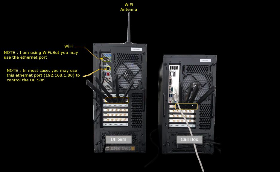
- Two physical setups are shown: Setup A (Callbox, UE, 2 SDRs) and Setup B (Callbox, UEsim, 1 SDR).
-
Key Configuration Parameters:
- dl_bwp_access, ul_bwp_access: Downlink/Uplink BWP access configuration.
- half_duplex and associated parameters: Control half-duplex operation and guard symbols.
- dl_bwp_list, ul_bwp_list: Lists of BWPs for DL/UL, respectively.
- initial_dl_bwp_id, initial_ul_bwp_id: Initial BWP selection for DL/UL.
-
Test 1: 20MHz BW, Single BWP
-
Procedure:
- Configure the network using gnb-sa-redcap.cfg and mme-ims.cfg as provided.
- Set FDD mode (NR_TDD 0), 2x2 MIMO (N_ANTENNA_DL 2), and 20MHz bandwidth (NR_BANDWIDTH 20).
- Use a single BWP shared by both regular and RedCap UEs.
- RedCap UE configuration uses the simplest default: half_duplex: { }.
- For UEsim, match FDD, bandwidth, and band settings to the Callbox.
- Ensure as_release is set to 17 and redcap to true in the UE list.
- Start LTE service, check NR cell configuration, and power on UEsim.
- Wait for initial connection completion.
-
Methodology Highlights:
- All RedCap traffic uses the single initial BWP (20MHz).
- RedCap-specific BWP is not used since channel bandwidth is not greater than 20MHz.
-
Procedure:
-
Test 2: 40MHz BW, Two BWPs with a RedCap-only BWP
-
Procedure:
- Use gnb-sa-redcap-2bwp.cfg and corresponding UE config.
- Set FDD mode (NR_TDD 0), 2x2 MIMO, and 40MHz channel bandwidth.
- Configure two BWPs: one for regular UE, one dedicated for RedCap UE.
- Enable full PHY/MAC scheduling (e.g., force_dl_schedule, force_full_bsr) for layer conformance checks.
- Configure two CSI reports: one for the initial BWP, one for RedCap BWP.
- For RedCap BWP, set ra_type to type0 (Bitmap) for non-contiguous allocation support.
- Create dedicated dl_bwp and ul_bwp for RedCap with 20MHz width.
- Assign initial BWP IDs and RedCap-specific BWP lists to RedCap UEs.
- For UEsim, match FDD, bandwidth, and band/frequency configuration.
- Start LTE service, verify NR cell configuration, and power on UEsim.
- Wait for initial connection completion.
-
Methodology Highlights:
- RedCap UEs use their dedicated BWPs for PRACH and subsequent PUSCH/PDSCH transmissions.
- Half-duplex scheduling is observed by default, with transition to full-duplex if not declared in UE capability.
-
Procedure:
-
Test 3: 40MHz BW, Three BWPs with Two RedCap-only BWPs and NCD-SSB
-
Procedure:
- Use gnb-sa-redcap-3bwp-ncdssb.cfg and corresponding UE config.
- Set up FDD mode, 2x2 MIMO, and 40MHz channel bandwidth.
- Configure three BWPs: one for regular UE, two for RedCap (one for initial attach, one for NCD-SSB transmission).
- Enable full PHY/MAC scheduling as in Test 2.
- Configure additional dl_bwp and ul_bwp for RedCap, each 10MHz wide. The second BWP for NCD-SSB includes ssb_nr_arfcn configuration.
- Assign initial and half-duplex BWP IDs to BWP 1 and 2 for RedCap UEs.
- For UEsim, ensure matching FDD, bandwidth, and band/frequency configuration.
- Start LTE service, check NR cell configuration, and power on UEsim.
- Wait for initial connection completion.
-
Methodology Highlights:
- RedCap UEs initiate PRACH on their dedicated BWP and perform all PUSCH/PDSCH operations in RedCap-only BWPs.
- One of the RedCap-only BWPs is used specifically for NCD-SSB, with position either automatically or explicitly configured.
- Half-duplex scheduling is used by default and switches to full-duplex if UE capability does not declare half-duplex support.
-
Procedure:
General Notes:
- For all tests, ensure the UE’s configuration matches the Callbox (cell bandwidth, band/frequency, FDD/TDD).
- RedCap features are enabled by setting as_release to 17 and redcap to true for the UE.
- Log analysis focuses on confirming RedCap feature signaling, BWP assignments, PRACH initiation, and operational mode (half/full duplex).
- Tests demonstrate stepwise extension from basic RedCap operation with a shared BWP to advanced scenarios with multiple RedCap-only BWPs and NCD-SSB handling.
Test Setup
Test setup for this tutorial is as shown below.
- SIM Card used in this tutorial is the one delivered with the system as it is.
- If you want to change the configuration, The tutorial Configuration Guide would help
< Setup A >

< Setup B >
Key Configuration Parameters
Followings are important configuration parameters for this tutorial. You may click on the items for the descriptions from Amarisoft documents.
Test 1 : 20Mhz BW, Single BWP
In this test, I will show on a simple redcap test scenario where only one BWP is configured and it is shared by both regular UE and RedCap devices.
Configuration
I used the gnb-sa-redcap.cfg which is provided with the installation package

I also used mme-ims.cfg as it is.

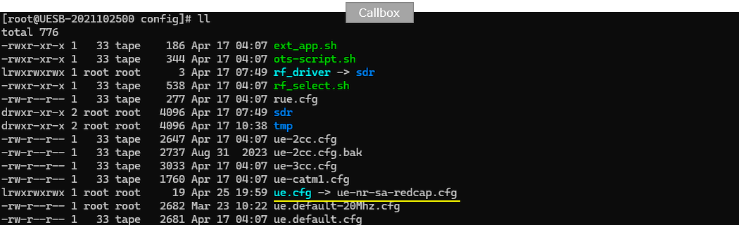
I used the ue-nr-sa-redcap.cfg which is provided with the installation package
Configure gnb-sa-redcap.cfg as below.
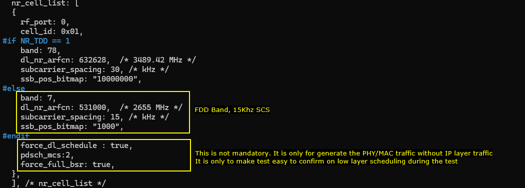
In this test, NR_TDD is set to 0, so the cell operates in NR FDD mode. NR_BANDWIDTH is set to 20, so the carrier bandwidth is 20 MHz. N_ANTENNA_DL is set to 2, so the downlink uses 2x2 MIMO. N_ANTENNA_UL is set to 1, so the uplink uses one transmit antenna. USE_SRS is set to 0, so periodic SRS is not enabled in this configuration. This creates a simple baseline RedCap test setup using a 20 MHz FDD cell with a single shared BWP.

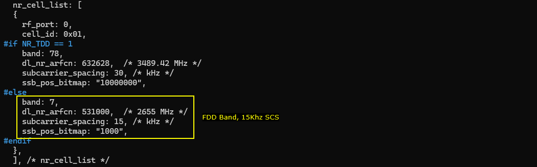
Since FDD is used in this test, the FDD configuration branch is selected in nr_cell_list. In this example, band is set to 7, dl_nr_arfcn is set to 531000, and the downlink frequency becomes 2655 MHz. subcarrier_spacing is set to 15, so the cell uses 15 kHz SCS. ssb_pos_bitmap is set to 1000, which defines the SSB position used for this FDD cell. This creates a basic NR FDD RedCap test cell using band n7 with 15 kHz subcarrier spacing.
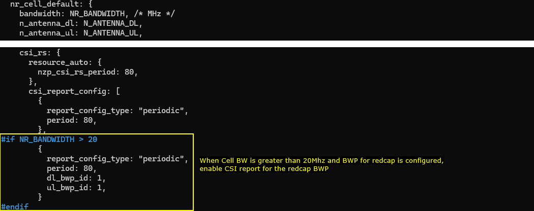
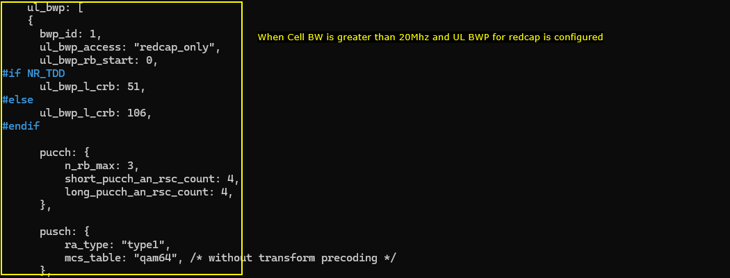
This part is only for information in this test. nr_cell_default uses NR_BANDWIDTH as the cell bandwidth, N_ANTENNA_DL as the number of downlink antennas, and N_ANTENNA_UL as the number of uplink antennas. The separate dl_bwp section shown here is enabled only when NR_BANDWIDTH is greater than 20 MHz. Since this test uses NR_BANDWIDTH 20, this RedCap-dedicated downlink BWP is not applied. Therefore, the RedCap UE and the regular UE use the same common BWP in this 20 MHz single-BWP test.
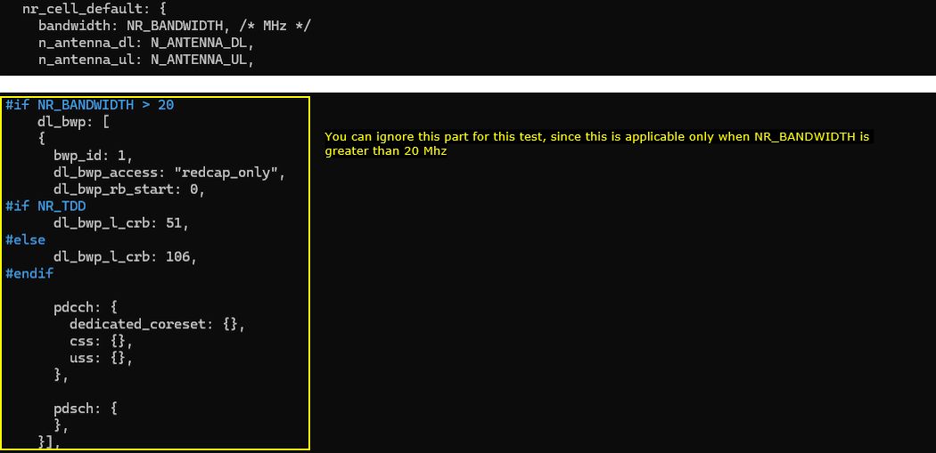
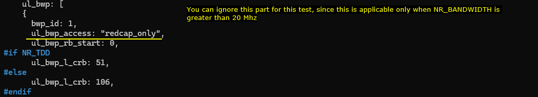
Same as the downlink BWP case, this uplink BWP section is not used in this specific test. The ul_bwp section defines a RedCap-only uplink BWP with bwp_id 1 and ul_bwp_access set to redcap_only, but this block is applied only when NR_BANDWIDTH is greater than 20 MHz. Since this test uses NR_BANDWIDTH 20, the separate RedCap uplink BWP is ignored. As a result, both the regular UE and the RedCap UE use the same uplink BWP in this 20 MHz single-BWP configuration.
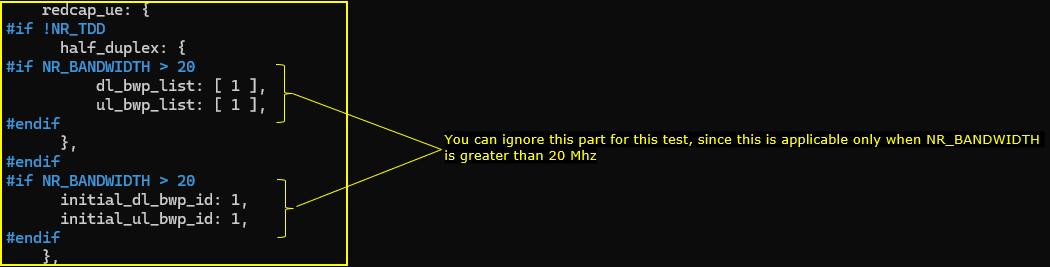
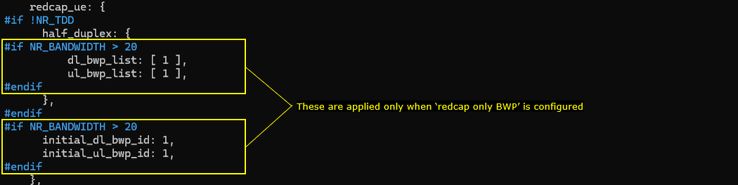
Now specify the RedCap-specific UE capability in the redcap_ue configuration. In this test, the simplest default RedCap configuration is used with redcap_ue and half_duplex enabled. The additional settings for dl_bwp_list, ul_bwp_list, initial_dl_bwp_id, and initial_ul_bwp_id are applied only when NR_BANDWIDTH is greater than 20 MHz. Since this test uses NR_BANDWIDTH 20, those BWP-related RedCap settings are not used. Therefore, this test only checks the basic RedCap UE operation with half-duplex support on the same shared BWP.
ue-nr-sa-redcap.cfg is configured as follows. (
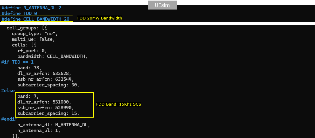
This part is required only when Amarisoft UEsim is used as the DUT. If a real mobile phone is used as the DUT, this UEsim configuration can be skipped. In this example, TDD is set to 0, so the UEsim uses FDD mode. CELL_BANDWIDTH is set to 20, so the UE expects a 20 MHz cell. In the FDD branch, band is set to 7, dl_nr_arfcn is set to 531000, ssb_nr_arfcn is set to 530910, and subcarrier_spacing is set to 15. These values should match the Callbox configuration so that the UEsim searches for the correct n7 FDD cell using 15 kHz SCS.
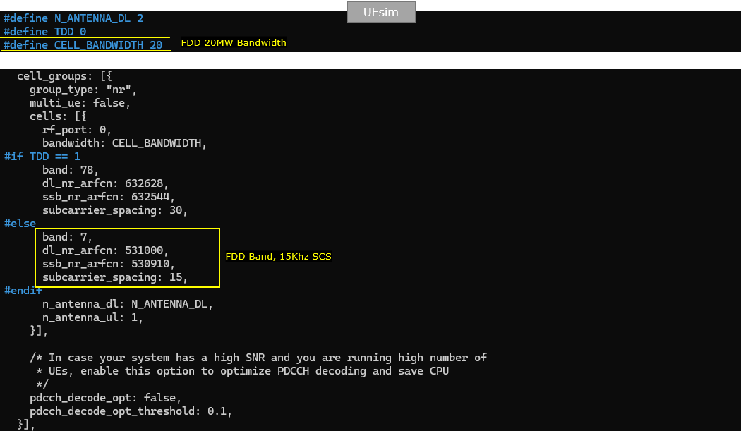
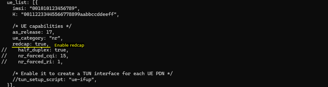
The ue_list configuration is simple for this test. Make sure as_release is set to 17 and redcap is set to true. as_release 17 enables Release 17 UE capability, which is required for NR RedCap. redcap true makes the UEsim behave as a RedCap UE. Other optional RedCap-related parameters, such as half_duplex, nr_forced_cqi, and nr_forced_ri, are commented out in this example, so the test uses the basic RedCap UE configuration.
Perform the test
Perform the test by starting the Callbox service and checking the basic cell configuration with cell phy. In this example, the cell is running as NR on band n7 with 20 MHz bandwidth. The downlink ARFCN is 531000, downlink antenna count is 2, number of layers is 2, and SCS is 15 kHz. The uplink ARFCN is 507000, uplink antenna count is 1, number of layers is 1, and SCS is also 15 kHz. The SSB ARFCN is 530910 with 15 kHz SCS. These values confirm that the Callbox cell is running with the expected 20 MHz FDD n7 configuration. (

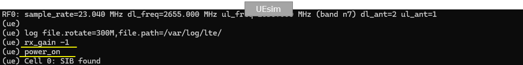
On UEsim, run power_on after the UE RF and logging parameters are ready. In this example, RF0 is configured with sample_rate 23.040 MHz, dl_freq 2655.000 MHz, band n7, dl_ant 2, and ul_ant 1. Before power_on, rx_gain is set to -1. This lets UEsim automatically adjust the RX gain, which is usually the easiest option when the exact RF condition is not known. If the channel condition is already known, a fixed rx_gain value can be used instead. After power_on, UEsim detects the cell and shows Cell 0: SIB found, which means the UE has successfully found the broadcast system information from the Callbox. (
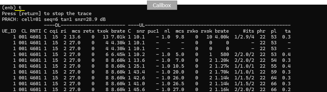
Wait until the initial connection is complete and monitor the Callbox trace. In this example, the PRACH line shows that the UE sent random access on cell 01 with seq 6, ta 1, and SNR 28.9 dB, so the uplink random access signal is clearly detected. After that, the UE is assigned RNTI 4601 and starts DL and UL scheduling. The DL side shows CQI 15, RI 2, and MCS increasing up to 27, which indicates good downlink radio quality with 2-layer transmission. The UL side also starts sending data with PUCCH and PUSCH activity, and the PHR and pathloss values are reported. This trace confirms that the RedCap UE has completed the initial access procedure and is now connected to the NR cell.
Log Analysis
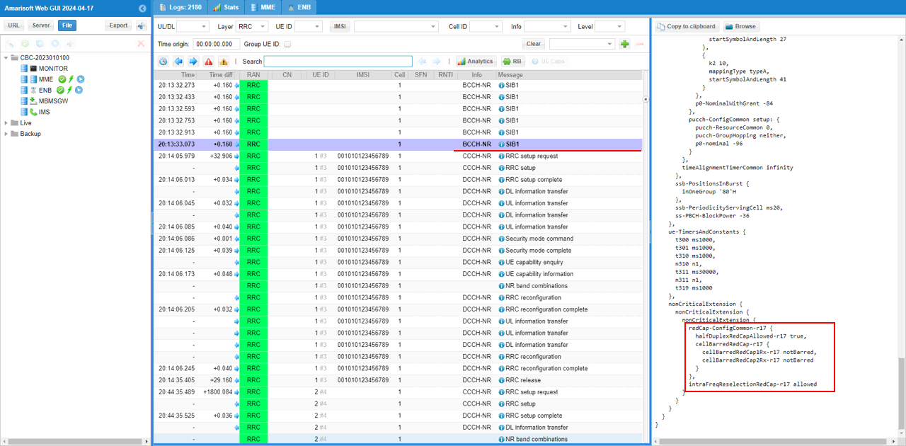
First check SIB1 because the gNB broadcasts the common RedCap support information before the UE starts the connection procedure. In this example, SIB1 includes redCap-ConfigCommon-r17 under nonCriticalExtension. halfDuplexRedCapAllowed-r17 is set to true, so the cell allows half-duplex RedCap UE operation. cellBarredRedCap-r17 is also included, and both cellBarredRedCap1Rx-r17 and cellBarredRedCap2Rx-r17 are set to notBarred, so RedCap UEs with 1Rx and 2Rx capability are allowed to access the cell. intraFreqReselectionRedCap-r17 is set to allowed, so intra-frequency cell reselection is also allowed for RedCap UEs. This confirms that the gNB is advertising RedCap support properly in SIB1.
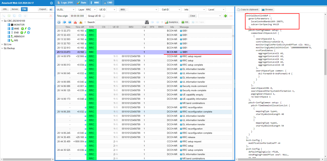
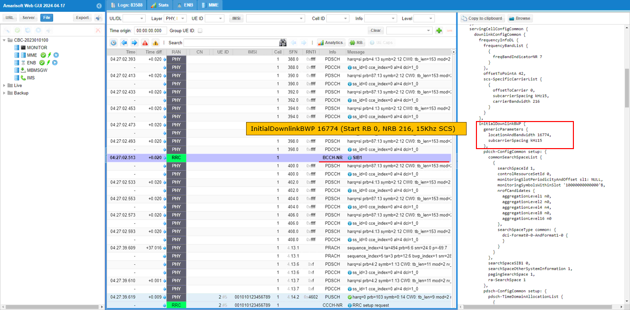
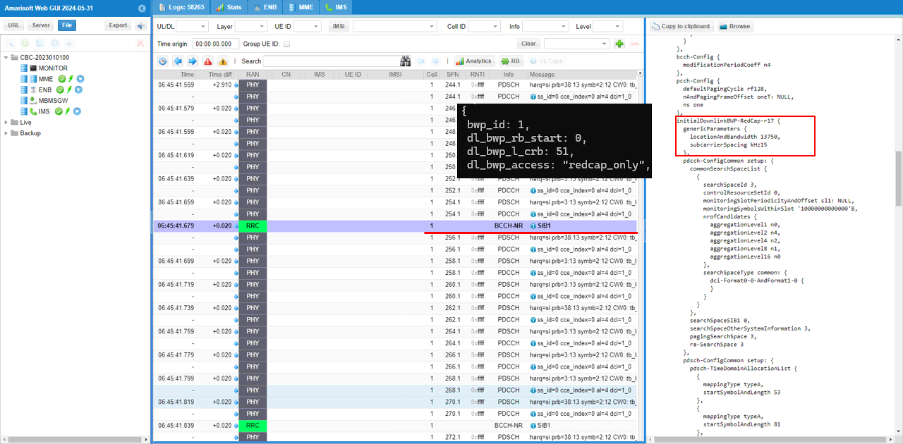
In SIB1, check the initialDownlinkBWP configuration. In this test, the initial downlink BWP is configured to cover the full 20 MHz channel bandwidth. The locationAndBandwidth value is 28875, which corresponds to StartRB 0 and NRB 106 for 15 kHz subcarrier spacing. This means the initialDownlinkBWP starts from the first RB of the carrier and spans the whole 20 MHz bandwidth. Since this test uses a single shared BWP, both the regular UE and the RedCap UE use this same initial downlink BWP.
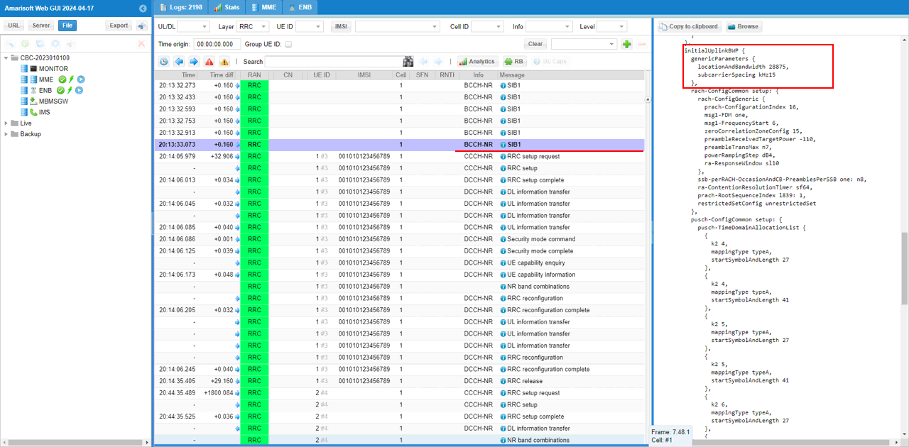
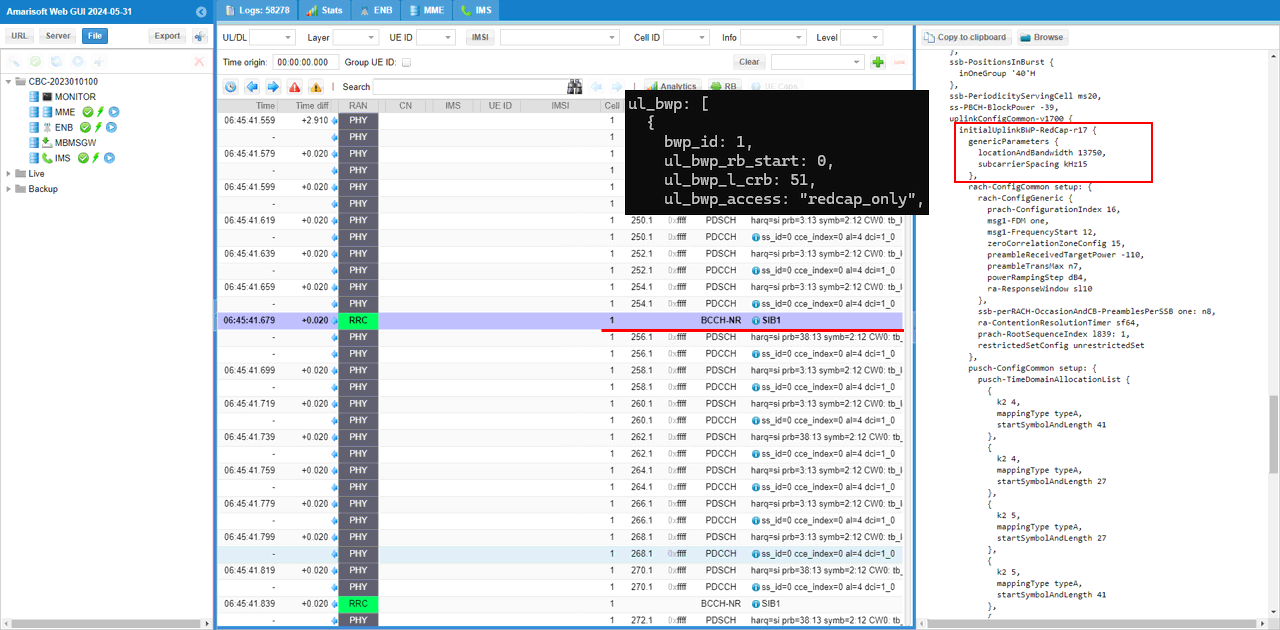
Then check the initialUplinkBWP configuration. In this test, the initial uplink BWP is also configured to cover the full 20 MHz channel bandwidth. The locationAndBandwidth value is 28875, which corresponds to StartRB 0 and NRB 106 for 15 kHz subcarrier spacing. This means the initialUplinkBWP starts from the first RB of the carrier and spans the whole 20 MHz bandwidth. Since this test does not use a separate RedCap-only uplink BWP, the RedCap UE uses this same initial uplink BWP for uplink access and data transmission.
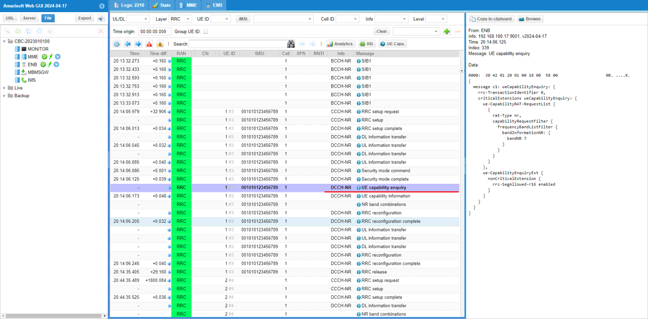
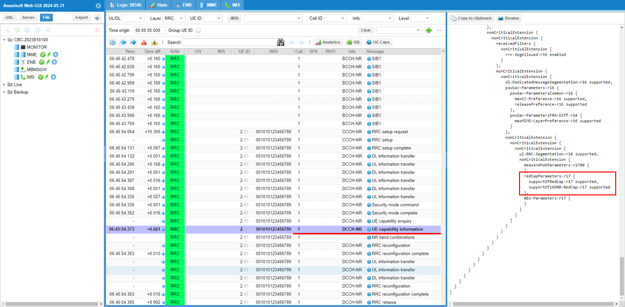
gNB sends UE capability enquiry to check the NR capability of the UE. In this test case, the enquiry is sent for bandNR 7 because the cell is configured as FDD band n7. The message includes UE-CapabilityRAT-RequestList with rat-Type set to nr, and the requested band information includes bandNR 7. This tells the UE to report its NR capability for the band used by the current cell. The message also includes rrc-SegAllowed-r16 enabled, which means RRC capability segmentation is allowed if the UE capability information is large.
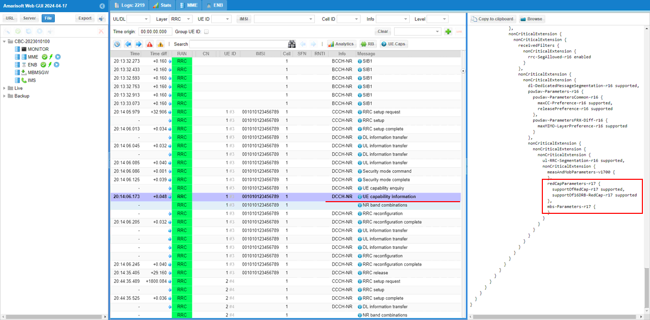
Confirm that the UE supports the RedCap feature by checking redCapParameters in the UE capability information message. In this example, the UE capability information includes redCapParameters-r17, and supportOfRedCap-r17 is set to supported. This confirms that the UE reports itself as a Release 17 RedCap UE. It also shows supportOf16DRB-RedCap-r17 supported, which means the UE supports up to 16 DRBs for RedCap operation. This capability response confirms that the DUT is recognized as a RedCap-capable UE by the gNB.
Test 2 : 40Mhz BW, Two BWPs with a RedCap-only BWP
In this test, I will show on a little bit extended redcap test scenario where two BWP are configured. One of the BWP is for regular UE and another one is dedicated for RedCap UE.
Configuration
I used the gnb-sa-redcap-2bwp.cfg which is provided with the installation package

I also used mme-ims.cfg as it is.
I used the ue-nr-sa-redcap-2bwp.cfg which is provided with the installation package

Configure gnb-sa-redcap-2bwp.cfg as below.
You can configure this part in any way you like. In this test, NR_TDD is set to 0, so the cell operates in NR FDD mode. NR_BANDWIDTH is set to 40, so the carrier bandwidth is 40 MHz. This is important because the RedCap-specific BWP is enabled only when the total channel bandwidth is greater than 20 MHz. N_ANTENNA_DL is set to 2, so the downlink uses 2x2 MIMO. N_ANTENNA_UL is set to 1, so the uplink uses one transmit antenna. USE_SRS is set to 0, so periodic SRS is not enabled. This creates a 40 MHz FDD baseline cell where an additional RedCap-only BWP can be configured.

Since FDD is used in this test, the FDD branch is selected in nr_cell_list. In this example, band is set to 7, dl_nr_arfcn is set to 531000, and subcarrier_spacing is set to 15, so the cell operates as an n7 FDD cell with 15 kHz SCS. ssb_pos_bitmap is set to 1000, which defines the SSB position for this FDD cell. In addition, force_dl_schedule is set to true and force_full_bsr is set to true. These settings are not mandatory for RedCap configuration itself. They are enabled here only to generate PHY/MAC scheduling activity without relying on IP layer traffic. This makes it easier to confirm low-layer DL and UL scheduling during the test.
Here, two CSI report configurations are prepared. The first CSI report is the default periodic CSI report for the initial BWP. In this example, the period is set to 80. When NR_BANDWIDTH is greater than 20, an additional CSI report is configured for BWP ID 1. This second CSI report also uses periodic reporting with period 80, but dl_bwp_id is set to 1 and ul_bwp_id is set to 1. This means the RedCap-dedicated BWP has its own CSI reporting configuration. This is needed because the RedCap UE operates on BWP 1 in this 40 MHz two-BWP test, so CSI measurement and reporting should also be associated with that RedCap BWP.
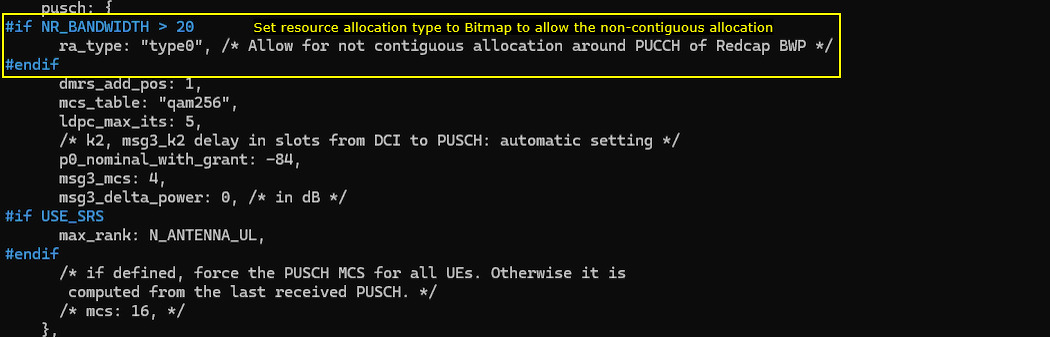
For this RedCap-dedicated BWP test, ra_type is set to type0 when NR_BANDWIDTH is greater than 20. type0 uses bitmap-based resource allocation, so it can support non-contiguous frequency allocation. This is useful in this test because the RedCap BWP has its own PUCCH region, and PUSCH allocation may need to avoid that area. By using bitmap-based allocation, the scheduler has more flexibility to allocate uplink resources around the PUCCH resources of the RedCap BWP.
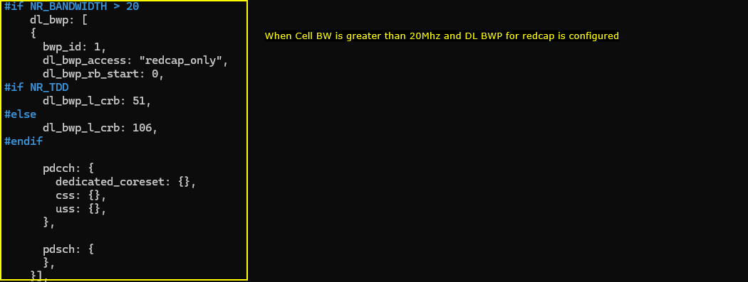
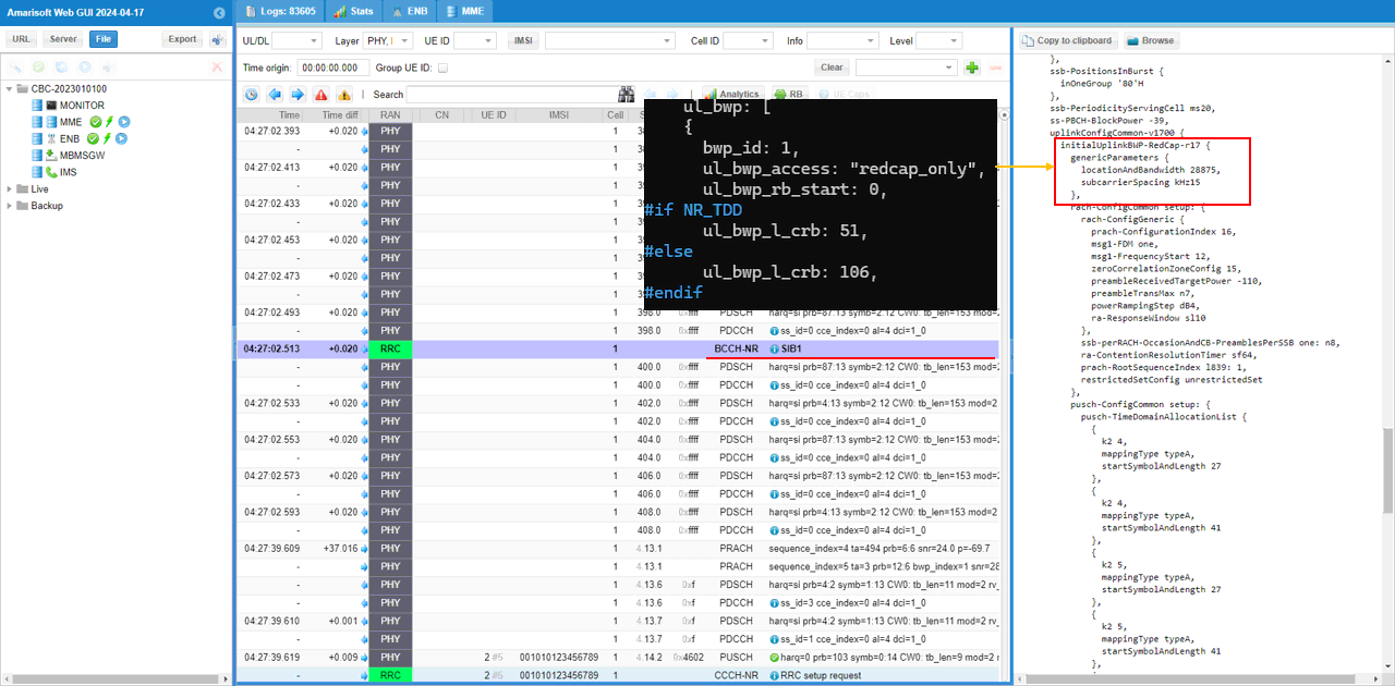
For the test with a RedCap-dedicated BWP, an additional downlink BWP is created when NR_BANDWIDTH is greater than 20. In this example, bwp_id is set to 1 and dl_bwp_access is set to redcap_only, so this BWP is used only by the RedCap UE. dl_bwp_rb_start is set to 0, so the RedCap BWP starts from the first RB of the configured BWP region. Since this test uses FDD with 15 kHz SCS, dl_bwp_l_crb is set to 106, which corresponds to 20 MHz bandwidth. This means the RedCap UE is restricted to a 20 MHz downlink BWP inside the larger 40 MHz carrier.
Same as the downlink BWP case, a RedCap-dedicated uplink BWP is also created in this test when NR_BANDWIDTH is greater than 20. In this example, bwp_id is set to 1 and ul_bwp_access is set to redcap_only, so this uplink BWP is used only by the RedCap UE. ul_bwp_rb_start is set to 0, so the RedCap uplink BWP starts from the first RB of the configured BWP region. Since this test uses FDD with 15 kHz SCS, ul_bwp_l_crb is set to 106, which corresponds to 20 MHz bandwidth. This allows the RedCap UE to use a 20 MHz uplink BWP inside the larger 40 MHz carrier. The PUCCH and PUSCH sections under this BWP define the uplink control and data channel behavior for the RedCap-only BWP.
Now specify the RedCap-specific UE configuration in redcap_ue. In this two-BWP test, the RedCap UE is assigned to BWP 1. dl_bwp_list is set to [ 1 ] and ul_bwp_list is set to [ 1 ], so the RedCap UE is allowed to use the RedCap-only downlink and uplink BWPs. initial_dl_bwp_id is set to 1 and initial_ul_bwp_id is also set to 1, so the RedCap UE starts operation directly on BWP 1. These settings are applied only when NR_BANDWIDTH is greater than 20, because the RedCap-only BWP is created only in that case. This makes BWP 1 the dedicated operating BWP for the RedCap UE in this 40 MHz test.
ue-nr-sa-redcap-2bwp.cfg is configured as follows. (
In this test, TDD is set to 0, so the UEsim uses FDD mode. CELL_BANDWIDTH should be set to 40 to match the 40 MHz Callbox configuration. In the FDD branch, band is set to 7, dl_nr_arfcn is set to 531000, ssb_nr_arfcn is set to 528990, and subcarrier_spacing is set to 15. These values should match the Callbox configuration so that the UEsim searches for the correct n7 FDD cell using 15 kHz SCS.
The ue_list configuration is the same as the previous test. Make sure as_release is set to 17 and redcap is set to true. as_release 17 enables Release 17 UE capability, and redcap true enables RedCap UE behavior in UEsim. In this example, half_duplex, nr_forced_cqi, and nr_forced_ri are commented out, so the UE uses the basic RedCap capability configuration. The important point for this test is that the UE advertises itself as a Release 17 RedCap UE, so the gNB can assign it to the RedCap-only BWP configured in the 40 MHz cell.
Perform the test
Start LTE service and check basic cell configuration. Any cell configuration is OK as long as they are all NR cell. (
In this example, the cell is running as NR on band n7 with 40 MHz bandwidth. The downlink ARFCN is 531000, downlink antenna count is 2, number of layers is 2, and SCS is 15 kHz. The uplink ARFCN is 507000, uplink antenna count is 1, number of layers is 1, and SCS is also 15 kHz. The SSB ARFCN is 528990 with 15 kHz SCS. These values confirm that the Callbox cell is running with the expected 40 MHz FDD n7 configuration.

On UEsim, power_on (
In this example, RF0 shows sample_rate 23.040 MHz, dl_freq 2655.000 MHz, band n7, dl_ant 2, and ul_ant 1. Before powering on the UE, rx_gain is set to -1. This lets UEsim automatically adjust the RX gain, which is usually the easiest setting when the exact RF condition is not known. If the RF path condition is already known, a fixed rx_gain value can be used instead. After power_on, UEsim shows Cell 0: SIB found, which means the UE has successfully detected the cell and decoded the system information from the Callbox.
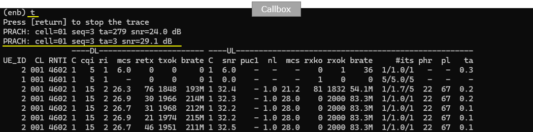
Wait until the initial connection is complete and monitor the Callbox trace. In this example, PRACH is detected twice on cell 01, first with seq 3, TA 279, and SNR 24.0 dB, and then again with seq 3, TA 3, and SNR 29.1 dB. After the connection is established, the UE is assigned RNTI 4602 and starts normal DL and UL scheduling. The DL side shows CQI 15, RI 2, and MCS around 26 to 27, which indicates good downlink radio quality with 2-layer transmission. The UL side shows SNR around 32 dB, MCS increasing up to 28, and a high UL bitrate around 83.3 Mbps. This confirms that the RedCap UE completed initial access and is actively scheduled on the 40 MHz cell with the RedCap-only BWP configuration.
Log Analysis
In the log analysis, first check SIB1 because the gNB broadcasts the common RedCap support information before the UE connection procedure. In this example, SIB1 includes redCap-ConfigCommon-r17 under nonCriticalExtension. halfDuplexRedCapAllowed-r17 is set to true, so the cell allows half-duplex RedCap UE operation. cellBarredRedCap-r17 shows cellBarredRedCap1Rx-r17 notBarred and cellBarredRedCap2Rx-r17 notBarred, so both 1Rx and 2Rx RedCap UEs are allowed to access the cell. intraFreqReselectionRedCap-r17 is set to allowed, so intra-frequency reselection is also allowed for RedCap UEs. This confirms that the 40 MHz cell is broadcasting RedCap support properly in SIB1 before assigning the RedCap UE to the dedicated BWP.
The initialDownlinkBWP is configured according to the channel bandwidth used in the configuration file. In this test, the cell bandwidth is 40 MHz, so initialDownlinkBWP uses locationAndBandwidth 16774. This value corresponds to Start RB 0 and NRB 216 with 15 kHz SCS, so the initial downlink BWP covers the full 40 MHz carrier. This is the default setting used in this test. The location and bandwidth of the initial BWP can be changed if needed, but in this example the initialDownlinkBWP is kept as the full carrier BWP while the RedCap UE later uses the separate RedCap-only BWP. (
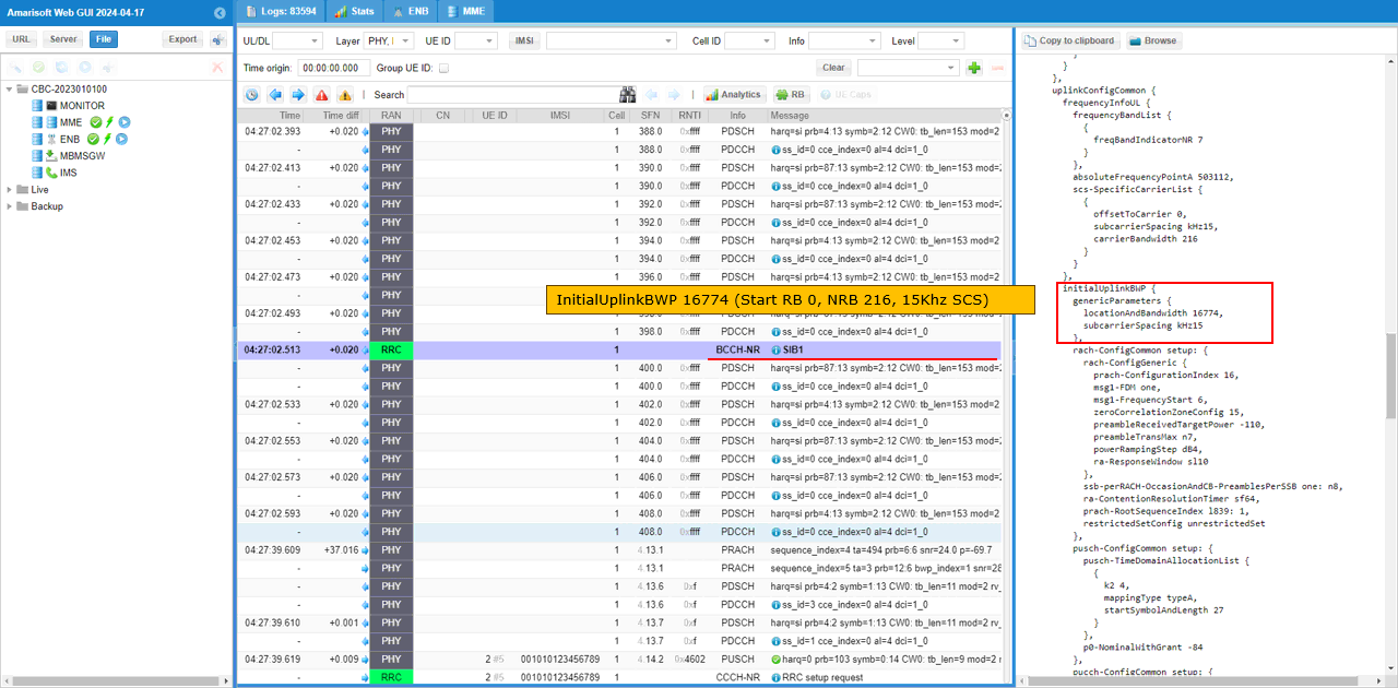
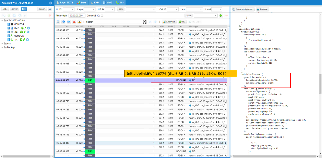
Same as the initial downlink BWP, the initialUplinkBWP is configured according to the channel bandwidth set in the configuration file. In this test, the cell bandwidth is 40 MHz, so initialUplinkBWP uses locationAndBandwidth 16774. This value corresponds to Start RB 0 and NRB 216 with 15 kHz SCS, so the initial uplink BWP covers the full 40 MHz carrier. This is the default setting used in this test. The location and bandwidth of the initial uplink BWP can be changed if needed, but in this example it is kept as the full carrier BWP while the RedCap UE uses the separate RedCap-only uplink BWP configured as BWP 1. (
The RedCap-only uplink BWP is configured in initialUplinkBWP-RedCap-r17. In this test, initialUplinkBWP-RedCap-r17 uses locationAndBandwidth 28875 with 15 kHz SCS. This corresponds to Start RB 0 and NRB 106, so the RedCap uplink BWP has 20 MHz bandwidth. This matches the ul_bwp configuration where bwp_id is set to 1, ul_bwp_access is set to redcap_only, ul_bwp_rb_start is set to 0, and ul_bwp_l_crb is set to 106. This confirms that the RedCap UE is given a separate 20 MHz uplink BWP inside the wider 40 MHz carrier.
The RedCap-only downlink BWP is configured in initialDownlinkBWP-RedCap-r17. In this test, initialDownlinkBWP-RedCap-r17 uses locationAndBandwidth 28875 with 15 kHz SCS. This corresponds to Start RB 0 and NRB 106, so the RedCap downlink BWP has 20 MHz bandwidth. This matches the dl_bwp configuration where bwp_id is set to 1, dl_bwp_access is set to redcap_only, dl_bwp_rb_start is set to 0, and dl_bwp_l_crb is set to 106. This confirms that the RedCap UE is assigned to a separate 20 MHz downlink BWP inside the wider 40 MHz carrier, instead of using the full 40 MHz initial downlink BWP.
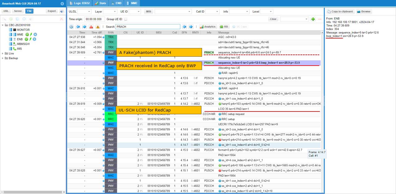
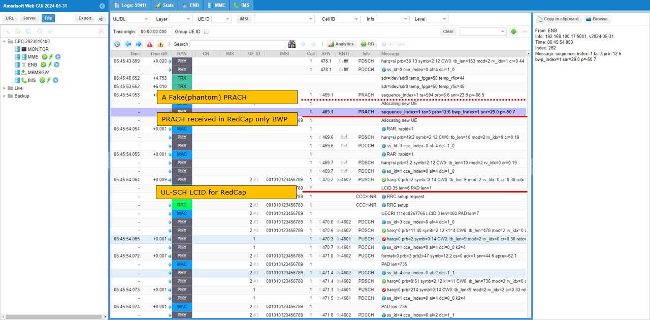
When the RedCap UE is powered on, it initiates PRACH through the RedCap-only BWP. In the log, the PRACH message shows bwp_index=1, which means the random access is received on BWP 1. This matches the configuration where BWP 1 is dedicated for RedCap operation. After PRACH, the UE sends RRC Setup Request, and the MAC log shows LCID 35, which is the UL-SCH LCID used for RedCap. From this behavior, the gNB can already recognize that the UE is a RedCap UE even before receiving the UE Capability Information message. In some cases, another PRACH may appear before the PRACH on the RedCap-only BWP. This can be treated as a fake or phantom PRACH detection on the gNB side and can be ignored for this test. (
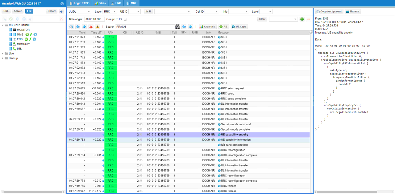
gNB sends UE Capability Enquiry after the RedCap UE completes the initial RRC connection steps. In this test, the purpose of this message is to check whether the UE supports RedCap and to find out the detailed RedCap capability supported by the UE. The enquiry requests NR capability information for bandNR 7, which matches the current n7 FDD test cell. The message also includes rrc-SegAllowed-r16 enabled, so the UE can use segmented capability reporting if the capability information is large. After this step, the UE should respond with UE Capability Information, and that response is used to confirm the RedCap capability details.
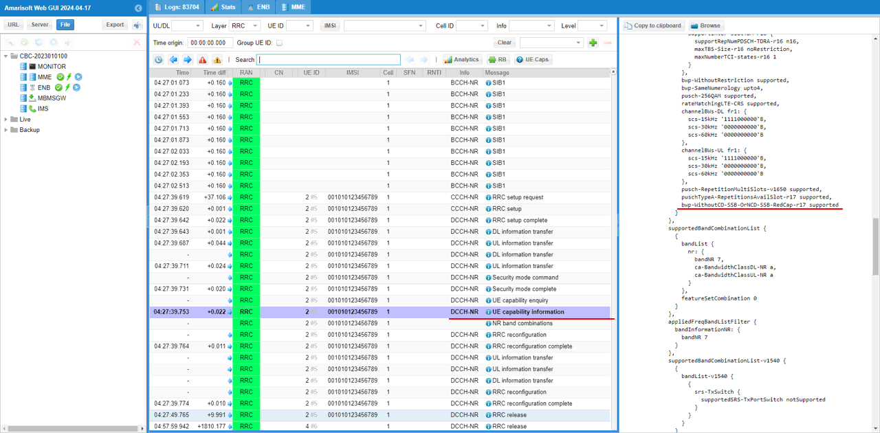
UE sends UE Capability Information with RedCap-related capability details. In this example, the UE reports bwp-WithoutCD-SSB-OrNCD-SSB-RedCap-r17 as supported. This means the UE can support a RedCap BWP even when CD-SSB or NCD-SSB is not configured in that BWP. For this specific test, this capability is not the main mandatory point to check. The important point is that the UE Capability Information contains RedCap-related Release 17 parameters and confirms that the UE can operate as a RedCap UE on the configured n7 cell and RedCap-only BWP.
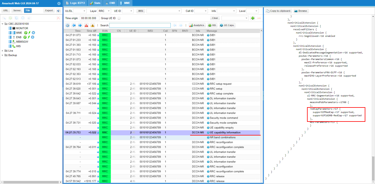
The important UE capability for this test is supportOfRedCap-r17 inside redCapParameters-r17. In this example, the UE Capability Information message includes redCapParameters-r17, and supportOfRedCap-r17 is set to supported. This confirms that the UE explicitly reports RedCap support to the gNB. The same section also shows supportOf16DRB-RedCap-r17 supported, which means the UE supports 16 DRBs for RedCap operation. With this capability information, the gNB can confirm that the UE is a Release 17 RedCap UE and can continue the connection using the RedCap-only BWP configured for this test.
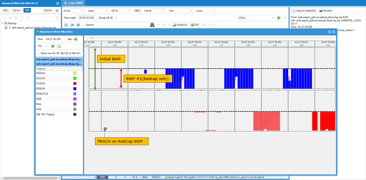
Now let�s look at the lower layer transactions with the RB map. In this view, PRACH is detected in the RedCap-only BWP, which is BWP 1 in this test. After the initial access, the subsequent PDSCH and PUSCH scheduling also stays inside the same RedCap-only BWP region. The initial BWP covers the wider 40 MHz carrier, but the actual RedCap UE activity is restricted to the smaller 20 MHz RedCap BWP. This confirms that the UE is not using the full carrier bandwidth after access. Instead, PRACH, downlink scheduling, and uplink scheduling are all handled inside BWP 1, which was configured as redcap_only.
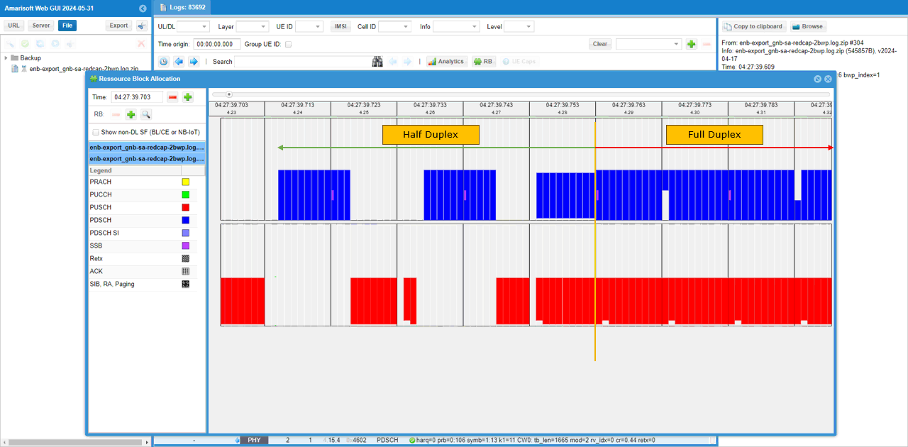
In this test, half-duplex scheduling is observed only during the early part of the connection. Before the UE capability information is received, the gNB assumes RedCap half-duplex operation by default, so DL and UL scheduling are separated in time. After the UE capability information is decoded, the scheduling changes to full-duplex behavior because the DUT does not report halfDuplexFDD-TypeA-RedCap-r17 support. In the RB map, the left side shows the half-duplex period where DL PDSCH and UL PUSCH do not overlap. After the capability check point, the right side shows full-duplex scheduling where DL and UL can be scheduled at the same time. This indicates that the final duplex behavior is determined by the RedCap capability reported by the UE.
Test 3 : 40Mhz BW, Three BWPs with two RedCap-only BWP and NCD-SSB
In this test, I will show on a further extended redcap test scenario where two BWP are configured. One of the BWP is for regular UE and the other two are dedicated for RedCap UE. One of the two redcap-only BWP is used for the initial BWP for the redcap device and the other one is to transmit NCD SSB.
Configuration
I used the gnb-sa-redcap-3bwp-ncdssb.cfg which is provided with the installation package

I also used mme-ims.cfg as it is.
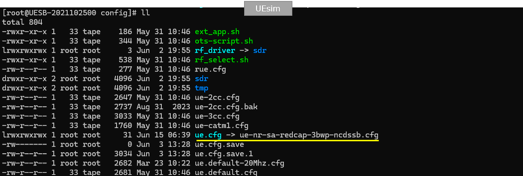
I used the ue-nr-sa-redcap-3bwp-ncdssb.cfg which is provided with the installation package
Configure gnb-sa-redcap-3bwp-ncdssb.cfg as below.
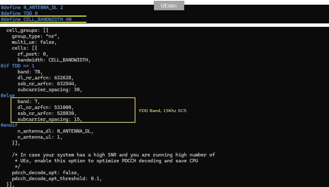
You can configure this part in any way you like. In this test, NR_TDD is set to 0, so the cell operates in NR FDD mode. NR_BANDWIDTH is set to 40, so the carrier bandwidth is 40 MHz. This is required because the RedCap-specific BWP configuration is applied only when the bandwidth is greater than 20 MHz. N_ANTENNA_DL is set to 2, so the downlink uses 2x2 MIMO. N_ANTENNA_UL is set to 1, so the uplink uses one transmit antenna. USE_SRS is set to 0, so periodic SRS is not enabled. This creates the baseline 40 MHz FDD cell for the three-BWP RedCap test with NCD-SSB.
Since FDD is used in this test, the FDD branch is selected in nr_cell_list. In this example, band is set to 7, dl_nr_arfcn is set to 531000, and subcarrier_spacing is set to 15, so the cell operates as an n7 FDD cell with 15 kHz SCS. ssb_pos_bitmap is set to 1000, which defines the SSB position for this FDD cell. force_dl_schedule is set to true and force_full_bsr is also set to true. These two settings are not mandatory for the RedCap NCD-SSB configuration itself. They are enabled only to generate PHY/MAC traffic without depending on IP layer traffic, so it becomes easier to check low-layer scheduling behavior during the test.
Here, two CSI report configurations are prepared. The first CSI report is used for the initial BWP, and it is configured as periodic CSI reporting with period 80. When NR_BANDWIDTH is greater than 20, an additional CSI report is configured for BWP 1, which is the RedCap-dedicated BWP in this test. This second CSI report also uses periodic reporting with period 80, but dl_bwp_id and ul_bwp_id are both set to 1. This allows the RedCap UE to perform CSI reporting on its own RedCap BWP instead of relying only on the initial BWP CSI configuration.
For this RedCap-dedicated BWP test, ra_type is set to type0 when NR_BANDWIDTH is greater than 20. type0 means bitmap-based PUSCH resource allocation. This allows non-contiguous uplink allocation, so the scheduler can allocate PUSCH resources while avoiding the PUCCH area of the RedCap BWP. This setting is useful when the RedCap UE operates in its own dedicated BWP and the uplink resource layout needs more flexibility around the RedCap PUCCH resources.
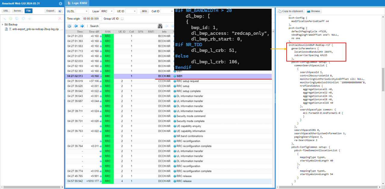
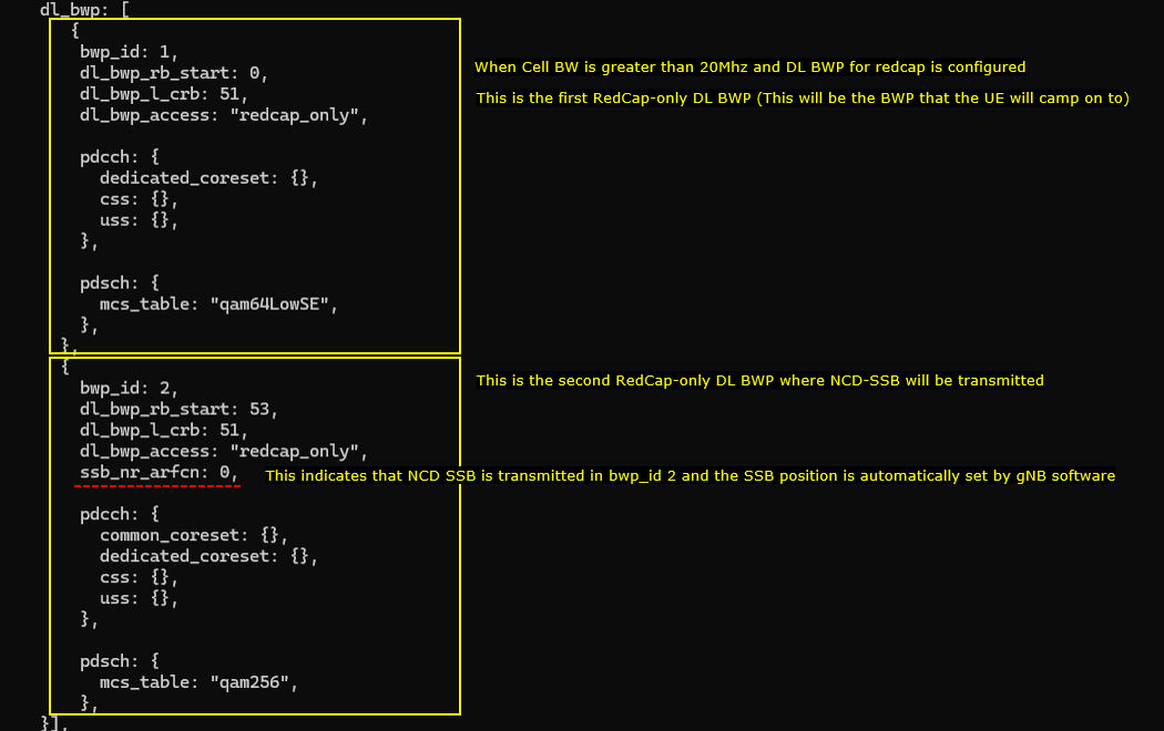
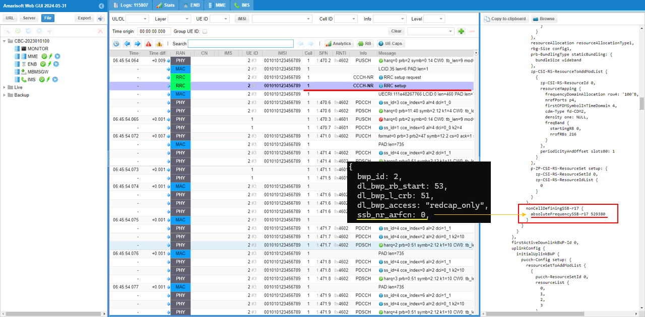
For the test with RedCap-dedicated BWP and NCD-SSB, two additional downlink BWPs are created. Each BWP has 10 MHz bandwidth because dl_bwp_l_crb is set to 51 with 15 kHz SCS. BWP 1 has bwp_id 1, dl_bwp_rb_start 0, and dl_bwp_access redcap_only. This is the first RedCap-only downlink BWP, and this is the BWP where the RedCap UE camps and starts operation. BWP 2 has bwp_id 2, dl_bwp_rb_start 53, dl_bwp_l_crb 51, and dl_bwp_access redcap_only. This is the second RedCap-only downlink BWP, and it is used for NCD-SSB transmission. In BWP 2, ssb_nr_arfcn is set to 0, which means the NCD-SSB position is automatically selected by the gNB software. If needed, ssb_nr_arfcn can also be set manually to force a specific NCD-SSB ARFCN.
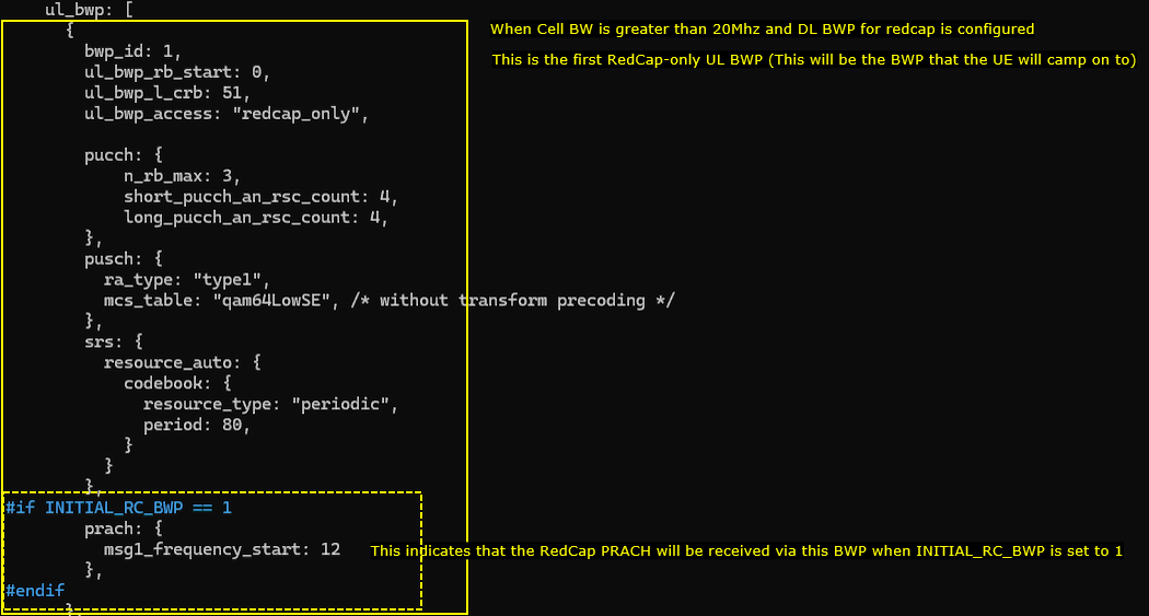
Same as the downlink case, a RedCap-dedicated uplink BWP is also created in this test. This is the first RedCap-only uplink BWP, and it is used for the initial access of the RedCap UE. In this example, bwp_id is set to 1, ul_bwp_rb_start is set to 0, ul_bwp_l_crb is set to 51, and ul_bwp_access is set to redcap_only. This means BWP 1 is a 10 MHz uplink BWP dedicated to RedCap operation. The PUCCH, PUSCH, and SRS sections define the uplink control, data, and sounding behavior inside this RedCap-only BWP. When INITIAL_RC_BWP is set to 1, the prach section is also enabled under this BWP, so the RedCap PRACH is received through BWP 1 during initial attach.
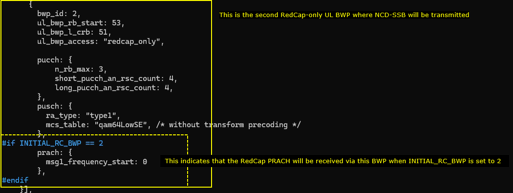
This is the second RedCap-only uplink BWP. In this example, bwp_id is set to 2, ul_bwp_rb_start is set to 53, ul_bwp_l_crb is set to 51, and ul_bwp_access is set to redcap_only. This means BWP 2 is another 10 MHz uplink BWP dedicated to RedCap operation. In this test, this BWP is paired with the RedCap downlink BWP where NCD-SSB is transmitted. The prach section is enabled only when INITIAL_RC_BWP is set to 2. In that case, the RedCap PRACH is received through BWP 2, and msg1_frequency_start is set to 0 for the PRACH resource inside this BWP.
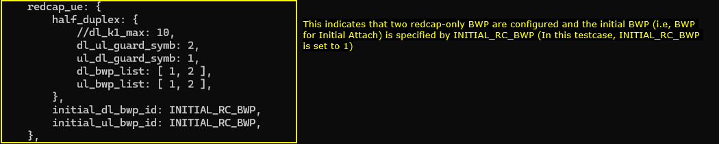
Now specify the RedCap-specific UE configuration in redcap_ue. In this test, two RedCap-only BWPs are assigned to the RedCap UE. dl_bwp_list is set to [ 1, 2 ] and ul_bwp_list is set to [ 1, 2 ], so the RedCap UE is allowed to use both BWP 1 and BWP 2. The initial downlink and uplink BWP are controlled by INITIAL_RC_BWP through initial_dl_bwp_id and initial_ul_bwp_id. In this example, INITIAL_RC_BWP is set to 1, so the RedCap UE performs initial attach on BWP 1. The half_duplex section also defines guard symbols for half-duplex operation, with dl_ul_guard_symb set to 2 and ul_dl_guard_symb set to 1. This configuration allows the RedCap UE to use two RedCap-only BWPs, while selecting BWP 1 as the initial access BWP for this test.
ue-nr-sa-redcap-3bwp-ncdssb.cfg is configured as follows. (
This part is required only when Amarisoft UEsim is used as the DUT. If a real mobile phone is used as the DUT, this UEsim configuration can be skipped. In this example, TDD is set to 0, so the UE uses FDD mode. CELL_BANDWIDTH is set to 40, so the UE expects a 40 MHz cell. In the FDD branch, band is set to 7, dl_nr_arfcn is set to 531000, ssb_nr_arfcn is set to 528030, and subcarrier_spacing is set to 15. These values should match the Callbox configuration so that UEsim searches for the correct n7 FDD cell with 15 kHz SCS and the proper SSB position used in this NCD-SSB test.
The ue_list configuration is the same as the previous RedCap tests. Make sure as_release is set to 17 and redcap is set to true. as_release 17 enables Release 17 UE capability, and redcap true makes the UEsim behave as a RedCap UE. In this example, half_duplex, nr_forced_cqi, and nr_forced_ri are commented out, so the UE uses the basic RedCap capability configuration. For this NCD-SSB test, the important point is that the UE advertises RedCap support so that the gNB can assign the UE to the configured RedCap-only BWP and apply the RedCap-specific BWP behavior.
Perform the test
Perform the test by starting the Callbox service and checking the basic cell configuration with cell phy. In this example, the cell is running as NR on band n7 with 40 MHz bandwidth. The downlink ARFCN is 531000, downlink antenna count is 2, number of layers is 2, and SCS is 15 kHz. The uplink ARFCN is 507000, uplink antenna count is 1, number of layers is 1, and SCS is also 15 kHz. The SSB ARFCN is 528030 with 15 kHz SCS. These values confirm that the Callbox cell is running with the expected 40 MHz FDD n7 configuration for the three-BWP RedCap NCD-SSB test. If UEsim is used as the DUT, make sure the UEsim band, bandwidth, DL ARFCN, SSB ARFCN, and SCS match these Callbox values before powering on the UE.

On UEsim, run power_on after confirming that the UE RF setting matches the 40 MHz n7 Callbox cell for the NCD-SSB test. In this example, RF0 shows sample_rate 23.040 MHz, dl_freq 2655.000 MHz, band n7, dl_ant 2, and ul_ant 1. Before power_on, rx_gain is set to -1. This lets UEsim automatically adjust the RX gain, which is usually the easiest option when the exact RF condition is not known. If the RF path condition is already known, a fixed rx_gain value can be used instead. After power_on, UEsim shows Cell 0: SIB found, which means the UE has successfully detected the cell and decoded the system information from the Callbox.
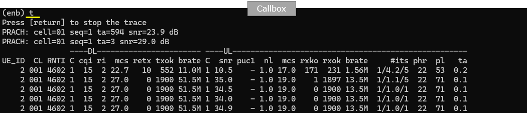
Wait until the initial connection is complete and monitor the Callbox trace. In this example, PRACH is detected twice on cell 01. The first one shows seq 1, TA 594, and SNR 23.9 dB, and the second one shows seq 1, TA 3, and SNR 29.0 dB. After the connection is established, the UE is assigned RNTI 4602 and starts DL and UL scheduling. The DL side shows CQI 15, RI 2, and MCS increasing up to 27, which indicates good downlink radio quality with 2-layer transmission. The UL side shows SNR around 34 to 35 dB, MCS 19, and UL bitrate around 13.5 Mbps. This confirms that the RedCap UE completed initial access successfully and is actively scheduled in the 40 MHz three-BWP NCD-SSB test configuration.
Log Analysis
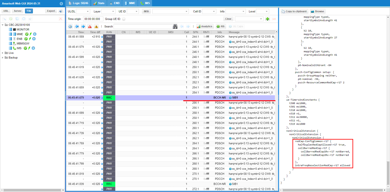
In the log analysis, first check SIB1 because the gNB broadcasts the common RedCap support information before the UE starts the connection procedure. In this example, SIB1 includes redCap-ConfigCommon-r17 under nonCriticalExtension. halfDuplexRedCapAllowed-r17 is set to true, so the cell allows half-duplex RedCap UE operation. cellBarredRedCap-r17 shows cellBarredRedCap1Rx-r17 notBarred and cellBarredRedCap2Rx-r17 notBarred, so both 1Rx and 2Rx RedCap UEs are allowed to access the cell. intraFreqReselectionRedCap-r17 is set to allowed, so intra-frequency reselection is also allowed for RedCap UEs. This confirms that the gNB is broadcasting RedCap support properly in SIB1 for the three-BWP NCD-SSB test.
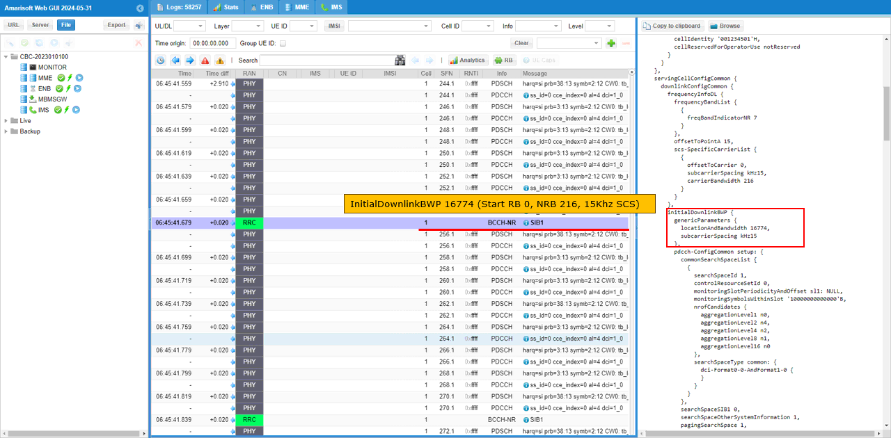
The initialDownlinkBWP is configured according to the channel bandwidth set in the configuration file. In this test, the cell bandwidth is 40 MHz, so initialDownlinkBWP uses locationAndBandwidth 16774. This corresponds to Start RB 0 and NRB 216 with 15 kHz SCS, so the initial downlink BWP covers the full 40 MHz carrier. This is the default setting used in this test. The location and bandwidth of the initial BWP can be changed if needed, but in this example the full 40 MHz initial downlink BWP is kept while the RedCap-specific BWPs are configured separately for RedCap operation and NCD-SSB. (
The initialDownlinkBWP is configured according to the channel bandwidth set in the configuration file. In this test, the cell bandwidth is 40 MHz, so initialDownlinkBWP uses locationAndBandwidth 16774. This corresponds to Start RB 0 and NRB 216 with 15 kHz SCS, so the initial downlink BWP covers the full 40 MHz carrier. This is the default setting used in this test. The location and bandwidth of the initial BWP can be changed if needed, but in this example the full 40 MHz initial downlink BWP is kept while the RedCap-specific BWPs are configured separately for RedCap operation and NCD-SSB.(
The RedCap-only BWP shown here is configured in initialDownlinkBWP-RedCap-r17. In this test, locationAndBandwidth is set to 13750 with 15 kHz SCS. This corresponds to Start RB 0 and NRB 51, so the RedCap BWP has about 10 MHz bandwidth. This matches the configured RedCap-only BWP where bwp_id is 1, rb_start is 0, l_crb is 51, and access is set to redcap_only. This means the RedCap UE is assigned to a 10 MHz RedCap-only BWP inside the wider 40 MHz carrier.
The RedCap-only uplink BWP is configured in initialUplinkBWP-RedCap-r17. In this test, locationAndBandwidth is set to 13750 with 15 kHz SCS. This corresponds to Start RB 0 and NRB 51, so the RedCap uplink BWP has about 10 MHz bandwidth. This matches the configured RedCap-only uplink BWP where bwp_id is 1, ul_bwp_rb_start is 0, ul_bwp_l_crb is 51, and ul_bwp_access is set to redcap_only. This means the RedCap UE uses a 10 MHz RedCap-only uplink BWP inside the wider 40 MHz carrier for initial access and uplink transmission.
When the RedCap UE is powered on, it initiates PRACH through the RedCap-only BWP. In the log, the valid PRACH shows bwp_index=1, which means the random access is received on BWP 1. This matches the configuration where BWP 1 is used as the initial RedCap BWP. After PRACH, the UE sends RRC Setup Request, and the MAC log shows LCID 35, which is the UL-SCH LCID used for RedCap. With this behavior, the gNB can identify the UE as a RedCap UE even before receiving the UE Capability Information message. In some cases, another PRACH may appear before the PRACH on the RedCap BWP. This can be treated as a fake or phantom PRACH detection on the gNB side and can be ignored for this test. (
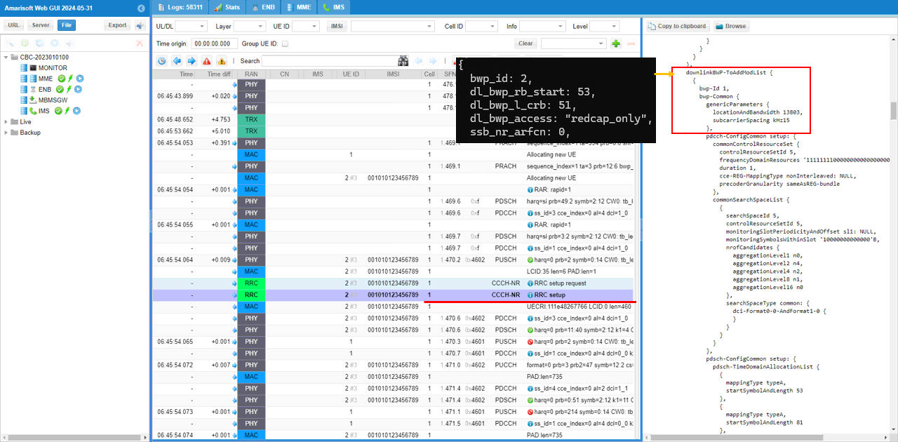
At the RRC Setup message, another RedCap-only downlink BWP is configured. This BWP is added through downlinkBWP-ToAddModList. In this example, the added BWP is bwp-Id 1 in the RRC message, and it corresponds to the configured BWP 2 in the Callbox configuration. This BWP has locationAndBandwidth 13803 with 15 kHz SCS, and it is the RedCap-only BWP where NCD-SSB is transmitted. In the configuration, this BWP is created with bwp_id 2, dl_bwp_rb_start 53, dl_bwp_l_crb 51, dl_bwp_access redcap_only, and ssb_nr_arfcn 0. The ssb_nr_arfcn 0 setting lets the gNB automatically choose the NCD-SSB position. This shows that the UE first accesses the initial RedCap BWP, and then the gNB adds another RedCap-only BWP for NCD-SSB operation during RRC Setup.
The NCD-SSB is configured by the ssb_nr_arfcn parameter in the RedCap-only BWP configuration. In this example, ssb_nr_arfcn is set to 0 in the configuration file, so the actual NCD-SSB ARFCN is automatically selected by the gNB software. In the RRC Setup message, this is signaled to the UE through nonCellDefiningSSB-r17. The decoded message shows absoluteFrequencySSB-r17 set to 529380, which is the actual NCD-SSB frequency selected for this test. This confirms that the second RedCap-only BWP is not only added as an extra BWP, but also configured with an NCD-SSB so the RedCap UE can use that BWP with its own non-cell-defining SSB reference. (
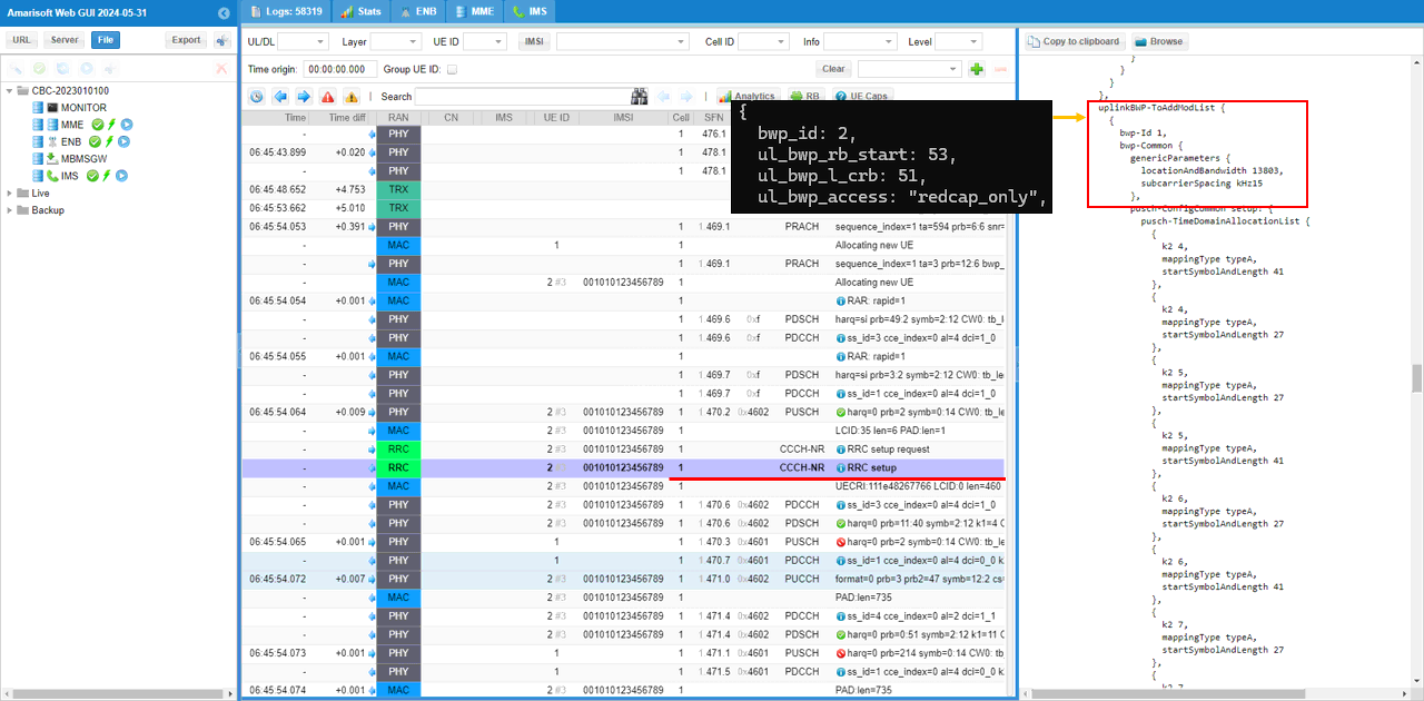
Same as the downlink case, the additional uplink BWP is also configured in the RRC Setup message. This BWP is added through uplinkBWP-ToAddModList and is also used as a RedCap-only BWP. In this example, the configured uplink BWP has bwp_id 2, ul_bwp_rb_start 53, ul_bwp_l_crb 51, and ul_bwp_access redcap_only. In the decoded RRC message, it appears as bwp-Id 1 with locationAndBandwidth 13803 and 15 kHz SCS. This means the UE receives an additional 10 MHz uplink BWP configuration that matches the second RedCap-only BWP. Together with the downlink BWP added earlier, this completes the DL and UL BWP pair used for the NCD-SSB related RedCap operation.
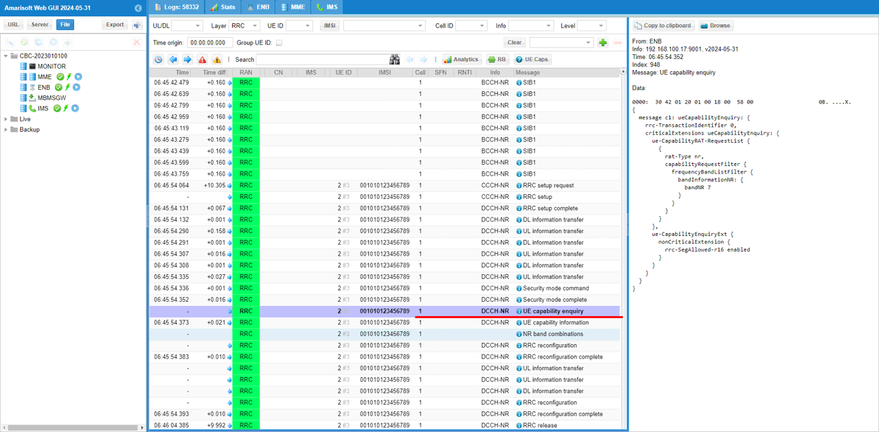
gNB sends UE Capability Enquiry after the RedCap UE completes the initial RRC setup procedure. In this test, the main purpose of this step is to check whether the UE supports RedCap and to identify the detailed RedCap feature set supported by the UE. The enquiry requests NR capability information for bandNR 7, which matches the current n7 FDD cell configuration. It also includes rrc-SegAllowed-r16 enabled, so the UE can send segmented capability information if the capability message becomes large. After this enquiry, the UE responds with UE Capability Information, and the gNB uses that response to confirm the RedCap capability details before continuing with the remaining RRC configuration.
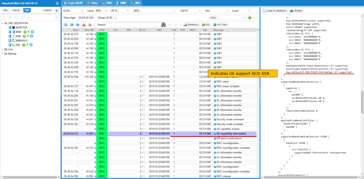
UE sends UE Capability Information with RedCap-related features. One important item shown here is bwp-WithoutCD-SSB-OrNCD-SSB-RedCap-r17, which is reported as supported. This indicates that the UE can support RedCap BWP operation related to CD-SSB or NCD-SSB cases. In this NCD-SSB test, this is an important capability because the gNB configures an additional RedCap-only BWP with nonCellDefiningSSB-r17. The UE also reports other RedCap-related Release 17 capabilities in the same capability information message, so the gNB can confirm that the DUT supports RedCap operation and can continue with the RedCap BWP and NCD-SSB related configuration.
The important UE capability for this test is supportOfRedCap-r17 inside redCapParameters-r17. In this example, the UE Capability Information message includes redCapParameters-r17, and supportOfRedCap-r17 is set to supported. This confirms that the UE explicitly declares RedCap capability to the gNB. The same section also shows supportOf16DRB-RedCap-r17 supported, which means the UE supports 16 DRBs for RedCap operation. With this information, the gNB can confirm that the DUT is a Release 17 RedCap UE and can continue with the RedCap-only BWP and NCD-SSB related configuration.
Now let�s look at the lower layer transactions with the RB map.
In this view, PRACH is detected in the RedCap-only BWP, which is BWP 1 in this test. After the initial access, the following PDSCH and PUSCH scheduling also stays inside the RedCap-only BWP region. The RB map also shows another RedCap-only BWP, BWP 2, where NCD-SSB is transmitted. The CD-SSB belongs to the normal cell-defining SSB, while the NCD-SSB is transmitted in the additional RedCap BWP. This confirms that the RedCap UE performs access and data scheduling on BWP 1, while another RedCap-only BWP is configured for NCD-SSB transmission.
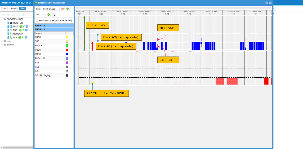
In this test, half-duplex scheduling is used only during the early part of the connection. Before the UE Capability Information is received, the gNB assumes RedCap half-duplex behavior, so DL and UL scheduling are separated in time. After the UE capability is decoded, the scheduling changes to full-duplex behavior because the DUT does not report halfDuplexFDD-TypeA-RedCap-r17 support. In the RB map, the left side shows the half-duplex period where PDSCH and PUSCH are not scheduled at the same time. After the transition point, the right side shows full-duplex scheduling where DL and UL allocations can overlap in time. This confirms that the final duplex mode is decided based on the RedCap capability reported by the UE.

RRC / NAS Signaling
SIB1
: This is the SIB1 message sent by eNB to declaire RedCap capability (
{
message c1: systemInformationBlockType1: {
cellSelectionInfo {
q-RxLevMin -70,
q-QualMin -20
},
cellAccessRelatedInfo {
plmn-IdentityInfoList {
{
plmn-IdentityList {
{
mcc {
0,
0,
1
},
mnc {
0,
1
}
}
},
trackingAreaCode '000064'H,
cellIdentity '001234501'H,
cellReservedForOperatorUse notReserved
}
}
},
connEstFailureControl {
connEstFailCount n1,
connEstFailOffsetValidity s30,
connEstFailOffset 1
},
servingCellConfigCommon {
downlinkConfigCommon {
frequencyInfoDL {
frequencyBandList {
{
freqBandIndicatorNR 7
}
},
offsetToPointA 42,
scs-SpecificCarrierList {
{
offsetToCarrier 0,
subcarrierSpacing kHz15,
carrierBandwidth 216
}
}
},
initialDownlinkBWP {
genericParameters {
locationAndBandwidth 16774,
subcarrierSpacing kHz15
},
pdcch-ConfigCommon setup: {
commonSearchSpaceList {
{
searchSpaceId 1,
controlResourceSetId 0,
monitoringSlotPeriodicityAndOffset sl1: NULL,
monitoringSymbolsWithinSlot '10000000000000'B,
nrofCandidates {
aggregationLevel1 n0,
aggregationLevel2 n0,
aggregationLevel4 n4,
aggregationLevel8 n0,
aggregationLevel16 n0
},
searchSpaceType common: {
dci-Format0-0-AndFormat1-0 {
}
}
}
},
searchSpaceSIB1 0,
searchSpaceOtherSystemInformation 1,
pagingSearchSpace 1,
ra-SearchSpace 1
},
pdsch-ConfigCommon setup: {
pdsch-TimeDomainAllocationList {
{
mappingType typeA,
startSymbolAndLength 40
}
}
}
},
bcch-Config {
modificationPeriodCoeff n4
},
pcch-Config {
defaultPagingCycle rf128,
nAndPagingFrameOffset oneT: NULL,
ns one
},
initialDownlinkBWP-RedCap-r17 {
genericParameters {
locationAndBandwidth 28875,
subcarrierSpacing kHz15
},
pdcch-ConfigCommon setup: {
commonSearchSpaceList {
{
searchSpaceId 3,
controlResourceSetId 0,
monitoringSlotPeriodicityAndOffset sl1: NULL,
monitoringSymbolsWithinSlot '10000000000000'B,
nrofCandidates {
aggregationLevel1 n0,
aggregationLevel2 n0,
aggregationLevel4 n4,
aggregationLevel8 n0,
aggregationLevel16 n0
},
searchSpaceType common: {
dci-Format0-0-AndFormat1-0 {
}
}
}
},
searchSpaceSIB1 0,
searchSpaceOtherSystemInformation 3,
pagingSearchSpace 3,
ra-SearchSpace 3
},
pdsch-ConfigCommon setup: {
pdsch-TimeDomainAllocationList {
{
mappingType typeA,
startSymbolAndLength 40
},
{
mappingType typeA,
startSymbolAndLength 54
}
}
}
}
},
uplinkConfigCommon {
frequencyInfoUL {
frequencyBandList {
{
freqBandIndicatorNR 7
}
},
absoluteFrequencyPointA 503112,
scs-SpecificCarrierList {
{
offsetToCarrier 0,
subcarrierSpacing kHz15,
carrierBandwidth 216
}
}
},
initialUplinkBWP {
genericParameters {
locationAndBandwidth 16774,
subcarrierSpacing kHz15
},
rach-ConfigCommon setup: {
rach-ConfigGeneric {
prach-ConfigurationIndex 16,
msg1-FDM one,
msg1-FrequencyStart 6,
zeroCorrelationZoneConfig 15,
preambleReceivedTargetPower -110,
preambleTransMax n7,
powerRampingStep dB4,
ra-ResponseWindow sl10
},
ssb-perRACH-OccasionAndCB-PreamblesPerSSB one: n8,
ra-ContentionResolutionTimer sf64,
prach-RootSequenceIndex l839: 1,
restrictedSetConfig unrestrictedSet
},
pusch-ConfigCommon setup: {
pusch-TimeDomainAllocationList {
{
k2 4,
mappingType typeA,
startSymbolAndLength 27
}
},
p0-NominalWithGrant -84
},
pucch-ConfigCommon setup: {
pucch-ResourceCommon 0,
pucch-GroupHopping neither,
p0-nominal -96
}
},
timeAlignmentTimerCommon infinity
},
ssb-PositionsInBurst {
inOneGroup '80'H
},
ssb-PeriodicityServingCell ms20,
ss-PBCH-BlockPower -39,
uplinkConfigCommon-v1700 {
initialUplinkBWP-RedCap-r17 {
genericParameters {
locationAndBandwidth 28875,
subcarrierSpacing kHz15
},
rach-ConfigCommon setup: {
rach-ConfigGeneric {
prach-ConfigurationIndex 16,
msg1-FDM one,
msg1-FrequencyStart 12,
zeroCorrelationZoneConfig 15,
preambleReceivedTargetPower -110,
preambleTransMax n7,
powerRampingStep dB4,
ra-ResponseWindow sl10
},
ssb-perRACH-OccasionAndCB-PreamblesPerSSB one: n8,
ra-ContentionResolutionTimer sf64,
prach-RootSequenceIndex l839: 1,
restrictedSetConfig unrestrictedSet
},
pusch-ConfigCommon setup: {
pusch-TimeDomainAllocationList {
{
k2 4,
mappingType typeA,
startSymbolAndLength 27
},
{
k2 4,
mappingType typeA,
startSymbolAndLength 41
},
{
k2 5,
mappingType typeA,
startSymbolAndLength 27
},
{
k2 5,
mappingType typeA,
startSymbolAndLength 41
},
{
k2 6,
mappingType typeA,
startSymbolAndLength 27
},
{
k2 6,
mappingType typeA,
startSymbolAndLength 41
},
{
k2 7,
mappingType typeA,
startSymbolAndLength 27
},
{
k2 7,
mappingType typeA,
startSymbolAndLength 41
},
{
k2 8,
mappingType typeA,
startSymbolAndLength 27
},
{
k2 8,
mappingType typeA,
startSymbolAndLength 41
},
{
k2 9,
mappingType typeA,
startSymbolAndLength 27
},
{
k2 9,
mappingType typeA,
startSymbolAndLength 41
},
{
k2 10,
mappingType typeA,
startSymbolAndLength 27
},
{
k2 10,
mappingType typeA,
startSymbolAndLength 41
}
},
p0-NominalWithGrant -84
},
pucch-ConfigCommon setup: {
pucch-GroupHopping neither,
p0-nominal -96,
pucch-ResourceCommonRedCap-r17 2
}
}
}
},
ue-TimersAndConstants {
t300 ms1000,
t301 ms1000,
t310 ms1000,
n310 n1,
t311 ms30000,
n311 n1,
t319 ms1000
},
nonCriticalExtension {
nonCriticalExtension {
nonCriticalExtension {
redCap-ConfigCommon-r17 {
halfDuplexRedCapAllowed-r17 true,
cellBarredRedCap-r17 {
cellBarredRedCap1Rx-r17 notBarred,
cellBarredRedCap2Rx-r17 notBarred
}
},
intraFreqReselectionRedCap-r17 allowed
}
}
}
}
}
RrcSetup
: This is the RrcSetup message sent by eNB to configure BWPs and other settings for RedCap (
{
message c1: rrcSetup: {
rrc-TransactionIdentifier 0,
criticalExtensions rrcSetup: {
radioBearerConfig {
srb-ToAddModList {
{
srb-Identity 1
}
}
},
masterCellGroup {
cellGroupId 0,
rlc-BearerToAddModList {
{
logicalChannelIdentity 1,
servedRadioBearer srb-Identity: 1,
mac-LogicalChannelConfig {
ul-SpecificParameters {
priority 1,
prioritisedBitRate infinity,
bucketSizeDuration ms5,
logicalChannelGroup 0,
schedulingRequestID 0,
logicalChannelSR-Mask FALSE,
logicalChannelSR-DelayTimerApplied FALSE
}
}
}
},
mac-CellGroupConfig {
schedulingRequestConfig {
schedulingRequestToAddModList {
{
schedulingRequestId 0,
sr-TransMax n64
}
}
},
bsr-Config {
periodicBSR-Timer sf20,
retxBSR-Timer sf320
},
tag-Config {
tag-ToAddModList {
{
tag-Id 0,
timeAlignmentTimer infinity
}
}
},
phr-Config setup: {
phr-PeriodicTimer sf500,
phr-ProhibitTimer sf200,
phr-Tx-PowerFactorChange dB3,
multiplePHR FALSE,
dummy FALSE,
phr-Type2OtherCell FALSE,
phr-ModeOtherCG real
},
skipUplinkTxDynamic FALSE
},
physicalCellGroupConfig {
pdsch-HARQ-ACK-Codebook dynamic
},
spCellConfig {
spCellConfigDedicated {
initialDownlinkBWP {
pdcch-Config setup: {
controlResourceSetToAddModList {
{
controlResourceSetId 4,
frequencyDomainResources '111111111111111110000000000000000000000000000'B,
duration 1,
cce-REG-MappingType nonInterleaved: NULL,
precoderGranularity sameAsREG-bundle
}
},
searchSpacesToAddModList {
{
searchSpaceId 4,
controlResourceSetId 4,
monitoringSlotPeriodicityAndOffset sl1: NULL,
monitoringSymbolsWithinSlot '10000000000000'B,
nrofCandidates {
aggregationLevel1 n0,
aggregationLevel2 n4,
aggregationLevel4 n0,
aggregationLevel8 n0,
aggregationLevel16 n0
},
searchSpaceType ue-Specific: {
dci-Formats formats0-1-And-1-1
}
}
}
},
pdsch-Config setup: {
dmrs-DownlinkForPDSCH-MappingTypeA setup: {
dmrs-AdditionalPosition pos1
},
tci-StatesToAddModList {
{
tci-StateId 0,
qcl-Type1 {
referenceSignal ssb: 0,
qcl-Type typeD
}
}
},
resourceAllocation resourceAllocationType1,
rbg-Size config1,
prb-BundlingType staticBundling: {
bundleSize wideband
},
zp-CSI-RS-ResourceToAddModList {
{
zp-CSI-RS-ResourceId 0,
resourceMapping {
frequencyDomainAllocation row4: '100'B,
nrofPorts p4,
firstOFDMSymbolInTimeDomain 4,
cdm-Type fd-CDM2,
density one: NULL,
freqBand {
startingRB 0,
nrofRBs 216
}
},
periodicityAndOffset slots80: 1
}
},
p-ZP-CSI-RS-ResourceSet setup: {
zp-CSI-RS-ResourceSetId 0,
zp-CSI-RS-ResourceIdList {
0
}
}
}
},
firstActiveDownlinkBWP-Id 0,
uplinkConfig {
initialUplinkBWP {
pucch-Config setup: {
resourceSetToAddModList {
{
pucch-ResourceSetId 0,
resourceList {
0,
1,
2,
3
}
},
{
pucch-ResourceSetId 1,
resourceList {
4,
5,
6,
7
}
}
},
resourceToAddModList {
{
pucch-ResourceId 0,
startingPRB 0,
format format0: {
initialCyclicShift 1,
nrofSymbols 1,
startingSymbolIndex 13
}
},
{
pucch-ResourceId 1,
startingPRB 105,
format format0: {
initialCyclicShift 2,
nrofSymbols 1,
startingSymbolIndex 0
}
},
{
pucch-ResourceId 2,
startingPRB 105,
format format0: {
initialCyclicShift 2,
nrofSymbols 1,
startingSymbolIndex 1
}
},
{
pucch-ResourceId 3,
startingPRB 105,
format format0: {
initialCyclicShift 2,
nrofSymbols 1,
startingSymbolIndex 2
}
},
{
pucch-ResourceId 4,
startingPRB 1,
intraSlotFrequencyHopping enabled,
secondHopPRB 104,
format format2: {
nrofPRBs 1,
nrofSymbols 2,
startingSymbolIndex 0
}
},
{
pucch-ResourceId 5,
startingPRB 1,
intraSlotFrequencyHopping enabled,
secondHopPRB 104,
format format2: {
nrofPRBs 1,
nrofSymbols 2,
startingSymbolIndex 2
}
},
{
pucch-ResourceId 6,
startingPRB 1,
intraSlotFrequencyHopping enabled,
secondHopPRB 104,
format format2: {
nrofPRBs 1,
nrofSymbols 2,
startingSymbolIndex 4
}
},
{
pucch-ResourceId 7,
startingPRB 1,
intraSlotFrequencyHopping enabled,
secondHopPRB 104,
format format2: {
nrofPRBs 1,
nrofSymbols 2,
startingSymbolIndex 6
}
},
{
pucch-ResourceId 8,
startingPRB 105,
format format0: {
initialCyclicShift 2,
nrofSymbols 1,
startingSymbolIndex 3
}
},
{
pucch-ResourceId 9,
startingPRB 1,
intraSlotFrequencyHopping enabled,
secondHopPRB 104,
format format2: {
nrofPRBs 1,
nrofSymbols 2,
startingSymbolIndex 8
}
}
},
format2 setup: {
maxCodeRate zeroDot25
},
schedulingRequestResourceToAddModList {
{
schedulingRequestResourceId 1,
schedulingRequestID 0,
periodicityAndOffset sl40: 0,
resource 8
}
},
dl-DataToUL-ACK {
4,
5,
6,
7,
8,
9,
10,
11
}
},
pusch-Config setup: {
txConfig codebook,
dmrs-UplinkForPUSCH-MappingTypeA setup: {
dmrs-AdditionalPosition pos1,
transformPrecodingDisabled {
}
},
pusch-PowerControl {
msg3-Alpha alpha1,
p0-AlphaSets {
{
p0-PUSCH-AlphaSetId 0,
p0 0,
alpha alpha1
}
},
pathlossReferenceRSToAddModList {
{
pusch-PathlossReferenceRS-Id 0,
referenceSignal ssb-Index: 0
}
},
sri-PUSCH-MappingToAddModList {
{
sri-PUSCH-PowerControlId 0,
sri-PUSCH-PathlossReferenceRS-Id 0,
sri-P0-PUSCH-AlphaSetId 0,
sri-PUSCH-ClosedLoopIndex i0
}
}
},
resourceAllocation resourceAllocationType1,
codebookSubset nonCoherent,
maxRank 1,
uci-OnPUSCH setup: {
betaOffsets semiStatic: {
betaOffsetACK-Index1 9,
betaOffsetACK-Index2 9,
betaOffsetACK-Index3 9,
betaOffsetCSI-Part1-Index1 7,
betaOffsetCSI-Part1-Index2 7,
betaOffsetCSI-Part2-Index1 7,
betaOffsetCSI-Part2-Index2 7
},
scaling f1
}
},
srs-Config setup: {
srs-ResourceSetToAddModList {
{
srs-ResourceSetId 0,
srs-ResourceIdList {
0
},
resourceType aperiodic: {
aperiodicSRS-ResourceTrigger 1,
slotOffset 7
},
usage codebook,
p0 -84,
pathlossReferenceRS ssb-Index: 0
}
},
srs-ResourceToAddModList {
{
srs-ResourceId 0,
nrofSRS-Ports port1,
transmissionComb n2: {
combOffset-n2 0,
cyclicShift-n2 0
},
resourceMapping {
startPosition 0,
nrofSymbols n1,
repetitionFactor n1
},
freqDomainPosition 0,
freqDomainShift 9,
freqHopping {
c-SRS 22,
b-SRS 3,
b-hop 0
},
groupOrSequenceHopping neither,
resourceType aperiodic: {
},
sequenceId 500
}
}
}
},
firstActiveUplinkBWP-Id 0,
pusch-ServingCellConfig setup: {
}
},
pdcch-ServingCellConfig setup: {
},
pdsch-ServingCellConfig setup: {
nrofHARQ-ProcessesForPDSCH n16
},
csi-MeasConfig setup: {
nzp-CSI-RS-ResourceToAddModList {
{
nzp-CSI-RS-ResourceId 0,
resourceMapping {
frequencyDomainAllocation other: '010000'B,
nrofPorts p2,
firstOFDMSymbolInTimeDomain 3,
cdm-Type fd-CDM2,
density one: NULL,
freqBand {
startingRB 0,
nrofRBs 216
}
},
powerControlOffset 0,
scramblingID 500,
periodicityAndOffset slots80: 1,
qcl-InfoPeriodicCSI-RS 0
},
{
nzp-CSI-RS-ResourceId 1,
resourceMapping {
frequencyDomainAllocation row1: '4'H,
nrofPorts p1,
firstOFDMSymbolInTimeDomain 5,
cdm-Type noCDM,
density three: NULL,
freqBand {
startingRB 0,
nrofRBs 216
}
},
powerControlOffset 0,
scramblingID 500,
periodicityAndOffset slots80: 1,
qcl-InfoPeriodicCSI-RS 0
},
{
nzp-CSI-RS-ResourceId 2,
resourceMapping {
frequencyDomainAllocation row1: '4'H,
nrofPorts p1,
firstOFDMSymbolInTimeDomain 9,
cdm-Type noCDM,
density three: NULL,
freqBand {
startingRB 0,
nrofRBs 216
}
},
powerControlOffset 0,
scramblingID 500,
periodicityAndOffset slots80: 1,
qcl-InfoPeriodicCSI-RS 0
},
{
nzp-CSI-RS-ResourceId 3,
resourceMapping {
frequencyDomainAllocation row1: '4'H,
nrofPorts p1,
firstOFDMSymbolInTimeDomain 5,
cdm-Type noCDM,
density three: NULL,
freqBand {
startingRB 0,
nrofRBs 216
}
},
powerControlOffset 0,
scramblingID 500,
periodicityAndOffset slots80: 2,
qcl-InfoPeriodicCSI-RS 0
},
{
nzp-CSI-RS-ResourceId 4,
resourceMapping {
frequencyDomainAllocation row1: '4'H,
nrofPorts p1,
firstOFDMSymbolInTimeDomain 9,
cdm-Type noCDM,
density three: NULL,
freqBand {
startingRB 0,
nrofRBs 216
}
},
powerControlOffset 0,
scramblingID 500,
periodicityAndOffset slots80: 2,
qcl-InfoPeriodicCSI-RS 0
}
},
nzp-CSI-RS-ResourceSetToAddModList {
{
nzp-CSI-ResourceSetId 0,
nzp-CSI-RS-Resources {
0
}
},
{
nzp-CSI-ResourceSetId 1,
nzp-CSI-RS-Resources {
1,
2,
3,
4
},
trs-Info true
}
},
csi-IM-ResourceToAddModList {
{
csi-IM-ResourceId 0,
csi-IM-ResourceElementPattern pattern1: {
subcarrierLocation-p1 s8,
symbolLocation-p1 4
},
freqBand {
startingRB 0,
nrofRBs 216
},
periodicityAndOffset slots80: 1
}
},
csi-IM-ResourceSetToAddModList {
{
csi-IM-ResourceSetId 0,
csi-IM-Resources {
0
}
}
},
csi-ResourceConfigToAddModList {
{
csi-ResourceConfigId 3,
csi-RS-ResourceSetList nzp-CSI-RS-SSB: {
nzp-CSI-RS-ResourceSetList {
0
}
},
bwp-Id 0,
resourceType periodic
},
{
csi-ResourceConfigId 4,
csi-RS-ResourceSetList csi-IM-ResourceSetList: {
0
},
bwp-Id 0,
resourceType periodic
},
{
csi-ResourceConfigId 5,
csi-RS-ResourceSetList nzp-CSI-RS-SSB: {
nzp-CSI-RS-ResourceSetList {
1
}
},
bwp-Id 0,
resourceType periodic
}
},
csi-ReportConfigToAddModList {
{
reportConfigId 0,
resourcesForChannelMeasurement 3,
csi-IM-ResourcesForInterference 4,
reportConfigType periodic: {
reportSlotConfig slots80: 1,
pucch-CSI-ResourceList {
{
uplinkBandwidthPartId 0,
pucch-Resource 9
}
}
},
reportQuantity cri-RI-PMI-CQI: NULL,
reportFreqConfiguration {
cqi-FormatIndicator widebandCQI,
pmi-FormatIndicator widebandPMI
},
timeRestrictionForChannelMeasurements notConfigured,
timeRestrictionForInterferenceMeasurements notConfigured,
codebookConfig {
codebookType type1: {
subType typeI-SinglePanel: {
nrOfAntennaPorts two: {
twoTX-CodebookSubsetRestriction '111111'B
},
typeI-SinglePanel-ri-Restriction '03'H
},
codebookMode 1
}
},
groupBasedBeamReporting disabled: {
},
cqi-Table table2,
subbandSize value1
}
}
},
tag-Id 0
}
}
}
}
}
}