BWP Setup / BWP Switching
The purpose of this tutorial is to show you how to add additional BWPs and Trigger BWP switching.
BWP is a mechanism newly introduced in NR by which we can split a channel bandwidth (CBW) into multiple (max 4) sub bandwidth so that a UE can perform all the call processing within a specified subband instead of handling the full bandwidth. Usually the bandwidth of a subband(i.e, a BWP) is configured to be smaller than the CBW (NOTE : In terms of the 3GPP standards, the bandwidth of a BWP can be same as a bandwidth of the whole channel, but in practice most of a BWP is configured to be smaller than the CBW).
If more than one BWPs are configured, it is possible for gNB to switch the current communication bandwidth (active BWP) to different BWPs as necessary. The switching is done by gNB using various triggers as illustrated below. Amarisoft gNB support all types of BWP switching mechanism shown below (NOTE : There are still some of the details that are not explictely specified in 3GPP, the detailed implemetation of some BWP switching mechanism is implemented with some assumption. Refer to Limitation section for the details)
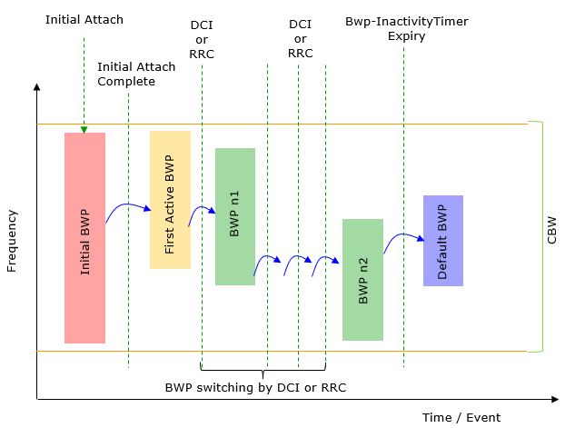
Image Source : BWP switching in Sharetechnote
In 3GPP specification, it is allowed to configure a max 4 BWPs within a CBW, but in the field I don't see many cases where a network configures the max number of BWPs as of writing this note. Most common mode of usage seems to be to configure two BWPs, one with wide bandwidth (e.g, almost same as CBW) and the other one with very narrow bandwidth (like 20 Mhz) and use the wide band BWP in regular communication and switch it to the narrower BWP when there is no traffic or low traffic to save energy consumption.
Table of Contents
- BWP Setup / BWP Switching
- Introduction
- Summary of the Tutorial
- Test Setup
- Key Configuration Parameters
- Test 1 : DCI 1_1 based BWP Switching with Dynamic Switch
- Test 2 : BWP Switching with Rrc Trigger
- Configuration
- Sub Test 1 : Throughput triggered RRC Transmission
- Sub Test 2 : RemoteAPI triggered RRC Transmission
- Test 3 : DCI-based Switch - UL Trigger
- Test 4 : DCI-based Switch - DL Trigger
- RRC / NAS Signaling
- Limitations
- RRC Based Switching
- Search Space Selection During Switching
- UL Resource Allocation Not Changing after Switch
- Tips
Introduction
Bandwidth Part (BWP) is a pivotal feature introduced in 5G New Radio (NR) that enables dynamic and efficient utilization of radio resources by partitioning the overall channel bandwidth (CBW) into multiple sub-bandwidths, known as BWPs. Each BWP represents a contiguous subset of the total available channel bandwidth, allowing User Equipment (UE) to operate within a narrower, more energy-efficient frequency range, rather than always processing the entire channel bandwidth. This architectural enhancement was standardized by 3GPP and is designed to address the diverse requirements of modern 5G networks, where use cases range from high-throughput data applications to ultra-low-power Internet of Things (IoT) devices. By configuring up to four BWPs within a single CBW, network operators and equipment vendors can flexibly allocate spectrum resources based on real-time traffic demands, service types, and UE capabilities. The gNB (5G base station) can dynamically trigger BWP switching using a variety of mechanisms, optimizing for power efficiency, latency, and throughput as network conditions change. This tutorial focuses on the practical aspects of adding additional BWPs and triggering BWP switching, equipping readers with the architectural understanding and procedural knowledge necessary for effective configuration and management in a 5G NR environment. The concepts covered herein are foundational to achieving both spectral efficiency and energy savings, which are critical goals in the evolution of mobile wireless technology.
-
Context and Background
- Bandwidth Part (BWP) is a core mechanism in 5G NR, enabling flexible channel partitioning and resource allocation.
- BWPs allow UEs to process only a segment of the channel bandwidth, reducing power consumption and supporting diverse service requirements.
- gNBs manage and switch between multiple BWPs based on network conditions and UE activity patterns.
-
Relevance and Importance
- Understanding BWP configuration and switching is essential for optimizing network performance, energy efficiency, and user experience in 5G deployments.
- The ability to dynamically switch BWPs enables networks to adapt to varying traffic loads, support low-latency applications, and extend device battery life.
- Mastery of BWP mechanisms is fundamental for network engineers, system integrators, and researchers working with 5G NR radio access networks.
-
Tutorial Objectives and Learning Outcomes
- Demonstrate how to configure additional BWPs within a 5G NR system.
- Explain the principles and triggers for BWP switching as implemented in commercial gNBs.
- Provide practical guidance and architectural insights for managing BWP configurations to achieve optimal energy and spectral efficiency.
- Empower learners to apply these concepts in real-world network design, optimization, and troubleshooting tasks.
-
Prerequisite Knowledge
- Familiarity with 5G NR architecture, including basic concepts such as gNB, UE, and channel bandwidth.
- Understanding of cellular radio resource management principles.
- Basic knowledge of 3GPP standards related to 5G NR.
- Experience with network configuration and troubleshooting tools is beneficial, though not mandatory.
Summary of the Tutorial
This tutorial covers multiple test procedures for configuring and verifying Bandwidth Part (BWP) switching in a 5G NR Standalone (SA) environment using an Amarisoft Callbox. The tests demonstrate both DCI-based and RRC-based BWP switching, with detailed setup, configuration, execution, and analysis steps. The procedures are structured as follows:
-
Test Setup:
- The test environment uses a SIM card provided with the system and requires internet access configuration, especially when using IP throughput as a BWP switching trigger. The Speedtest website is used for traffic generation, but alternatives such as iperf or LteSimserver can simplify the setup.
- Internet connectivity for the Callbox is established through one of several methods, with command-line Linux tools (e.g., nmcli) used for WiFi setup if necessary.
-
Key Configuration Parameters:
- Critical parameters for BWP configuration include dl_bwp, ul_bwp, bwp_id, dl_bwp_id, ul_bwp_id, first_active_dl_bwp_id, default_dl_bwp_id, dl_bwp_rb_start, dl_bwp_l_crb, ul_bwp_rb_start, ul_bwp_l_crb, bwp_dynamic_switch, and related subparameters for threshold settings.
-
Test 1: DCI 1_1 based BWP Switching with Dynamic Switch
- Configuration is based on a modified gnb-sa-n78-40Mhz-BwpSwitch.cfg file, with BWP settings placed within the nr_cell_default section at appropriate hierarchy levels.
- Parameters for dynamic BWP switching (including throughput thresholds and probe timing) are set to trigger BWP changes based on IP throughput.
- Pre-checks include verifying network interfaces, routing tables, and internet connectivity (e.g., pinging external servers and DNS resolution).
- Test execution involves disabling WiFi on the UE, performing initial network attach, confirming IP assignment, and validating connectivity via ping and web browsing.
- High data rate traffic is generated using a speed test site to invoke dynamic BWP switching.
- Log analysis includes verifying initial BWP configurations, monitoring BWP changes in DCI messages, and visually confirming throughput and resource allocation changes in the WebGUI.
-
Test 2: BWP Switching with RRC Trigger
- This test demonstrates BWP switching triggered by RRC messages via two methods: throughput-based and RemoteAPI-based triggers.
- Configuration requires enabling rrc_based_bwp_switch and allow_rrc_bwp_switch parameters to facilitate RRC-based BWP switching and proper PUCCH resource creation.
-
Sub Test 1: Throughput triggered RRC Transmission
- IP traffic is generated (e.g., using LteSimServer), and when throughput crosses configured thresholds, an RRC Reconfiguration is triggered to switch the active BWP.
- Logs are analyzed to confirm the RRC messages for BWP switching and to observe the corresponding changes at the lower layers.
-
Sub Test 2: RemoteAPI triggered RRC Transmission
- The same setup and configuration are used as in Test 1, but BWP switching is triggered by sending a rrc_cnx_reconf message via RemoteAPI commands.
- Successful execution is confirmed by monitoring the RRC messages and BWP changes in the logs.
-
Test 3: DCI-based Switch - UL Trigger
- This test focuses on triggering BWP switching using DCI 0_1 (uplink) via RemoteAPI.
- Configuration changes from Test 1 include adding bwp_switch_k0 in the pdsch section and removing the bwp_dynamic_switch configuration.
- After UE attachment, BWP switching is triggered by sending the dci_bwp_switch command with the target UL BWP ID using RemoteAPI.
- Analysis consists of verifying configuration changes and confirming DCI messages indicate the expected BWP before and after switching.
-
Test 4: DCI-based Switch - DL Trigger
- This test is analogous to Test 3 but applies the DCI 0_1-based trigger for the downlink direction.
- Configuration modifications are similar to those in Test 3, focusing on bwp_switch_k0 and commenting out bwp_dynamic_switch.
- The dci_bwp_switch RemoteAPI command is used to initiate BWP switching, with continuous ping recommended to keep the call state active.
- Logs are checked for correct DCI messages and confirmation that BWP indices transition as intended.
-
Limitations and Tips:
- The tutorial discusses current limitations and ambiguities in 3GPP specifications regarding RRC-based BWP switching and search space selection during switching events.
- Tips are provided for resolving common configuration warnings, such as ensuring CoReSet 0 is included in all DL BWPs and UL BWP #0 is encompassed by other UL BWPs.
- Guidance is also given for adjusting resource allocation settings to address possible mismatches in uplink resource sizes after BWP switching.
Throughout the tutorial, strict attention is given to configuration hierarchy, correct parameter placement, and the use of both GUI and command-line tools for verification and troubleshooting. Each test provides a structured methodology for validating BWP switching functionality in both downlink and uplink directions, using dynamic, RRC, and RemoteAPI triggers.
Test Setup
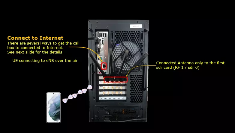
Test setup for this tutorial is as shown below.
- SIM Card used in this tutorial is the one delivered with the system as it is.
- If you want to change the configuration, The tutorial Configuration Guide would help
There are several many ways to provide internet access to your CallBox. Followings are some of them I can think of. In this tutorial, I used the Case 4.
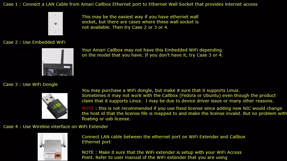
If you decided to use Case 2 and Case 3, following tips would be helpful.
Since Amari Callbox is running command line mode of Linux (Fedora or Ubuntu) NOT on GUI , it is not straightforward to enable / connect WiFi.
Followings are some of the command line command you would need to get WiFi connectivity. You may search these commands on internet for the detailed usage.
# nmcli dev status
# nmcli radio wifi
# nmcli device wifi rescan
# nmcli dev wifi list
# nmcli dev wifi connect network-ssid password "network-password"
Key Configuration Parameters
Followings are important configuration parameters for this tutorial. You may click on the items for the descriptions from Amarisoft documents.
- dl_bwp
- ul_bwp
- bwp_id
- dl_bwp_id
- ul_bwp_id
- first_active_dl_bwp_id
- default_dl_bwp_id
- dl_bwp_rb_start
- dl_bwp_l_crb
- ul_bwp_rb_start
- ul_bwp_l_crb
- bwp_dynamic_switch
- bwp_switch_k0
- dci_bwp_switch
- rrc_cnx_reconf
- rrc_based_bwp_switch
- allow_rrc_bwp_switch
Test 1 : DCI 1_1 based BWP Switching with Dynamic Switch
Configuration
I used enb.default.cfg as the configuration for this tutorial but you may use any configuration as long as your DUT(UE) would support it.
I have used gnb-sa-n78-40Mhz-BwpSwitch.cfg which is copied and modified from gnb-sa.cfg .

I am using the default mme(mme-ims.cfg) , ims (ims.default.cfg) config as shown below.

The major modification/addition in gnb-sa-n78-40Mhz-BwpSwitch.cfg goes as follows :
I put all the bwp setting parameters in nr_cell_default: {}

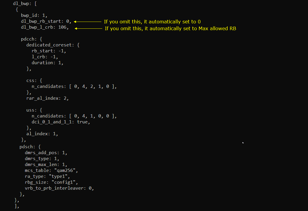
Within nr_cell_default: { }, put bwp related parameters as follows. Actually the exact location of those parameters is not that critical, but the level (e.g, root level, sub parameter of a root level parameter etc) is important.
I put the following between prach:{} and pdcch:{}

I put the following between pdsch:{} and pdcch:{}
I put the following between csi_report_config:{} and pucch:{}

I put the following between pusch:{} and bwp_dynamic_switch:{}
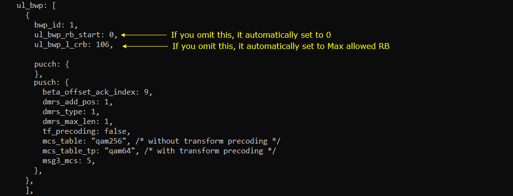
I put the following between ul_bwp:[] and mac_config:{}

NOTE : The DL and UL bit rate is ORed to trigger BWP switching
NOTE : There are a few other parameters that are not used in this tutorial.
probe_interval (default set to 50 ms)
probe_counter_threshold (default set to 3)
when probe_counter_threshold consecutive measure of the throughput are above the threshold, then BWP switch is initiated
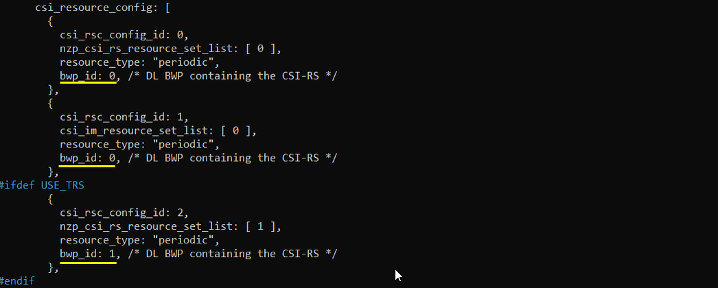
Add following lines to csi_resource_config: [ ]
Check Up before trying UE connection
Before you trying internet connection with UE, you need to check several basic things shown in this section and make it sure everything works as shown here, otherwise Internet connection from UE may not work.
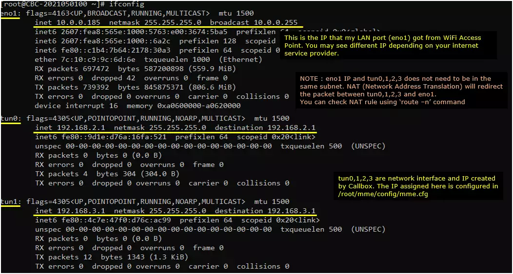
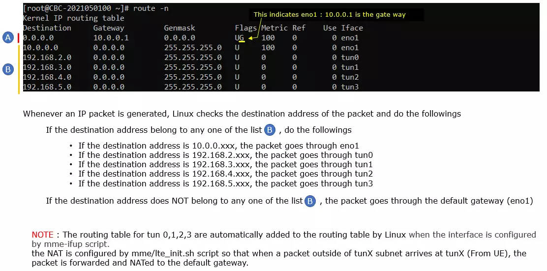
Make it sure that the network interface with internet connectivity is up and tun0,1,2,3 are up.
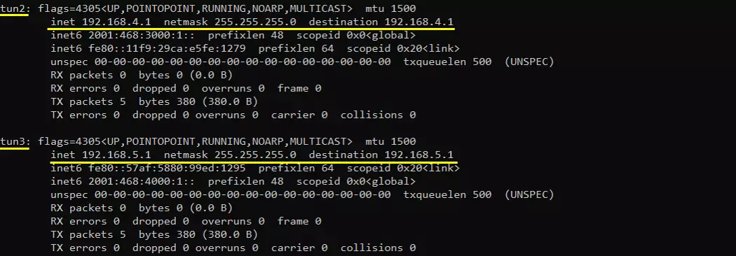
Check up the routing table on CallBox PC. It would usually be as follows. (NOTE : The gateway Iface name may be different on your system depending on your system configuration. But you should see tun0, tun1, tun2, tun3 as shown below)
Make it sure that the call box can reach a server over the internet. I am checking the connectivity as follows
Try ping to 8.8.8.8. This is google DNS and this is configured as DNS by default in mme.cfg

Try ping to a url to check the DNS is working

[Optional] you may find the IP address to a specific url and try ping to the server with both in direct IP and url

Perform the Test
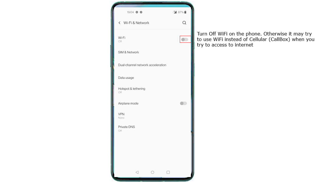
Before you trying to connect internet from your UE (DUT), you would suggest you to check up a few things first. Firs thing I would suggest is to disable WiFi on UE, otherwise most of UE would give higher priority to WiFi for data connection than cellular connection. So if WiFi is not disabled, UE would try to connect internet over WiFi instead of celluar network. (
Do the initial attach and confirm that UE is connected to Callbox. If you started 't' command before you powe on UE, you will get the traces for PRACH attempt. The presence of PRACH trace can be a good troubleshooting indicator for initial attach problem. If PRACH is properly received and the entire RACH process is completed, it is highly likely that the initial attach gets completed and start getting traffic log. Regarding the details on the meaning of each column of this log and how to use the information for troubleshoot, refer to this tutorial.

Confirm that UE is assigned with an IP. At least you should see at least one IP here. Otherwise, you need to troubleshoot it first to have at least one IP assigned to UE.

Ping from Callbox to UE and confirm that ping works

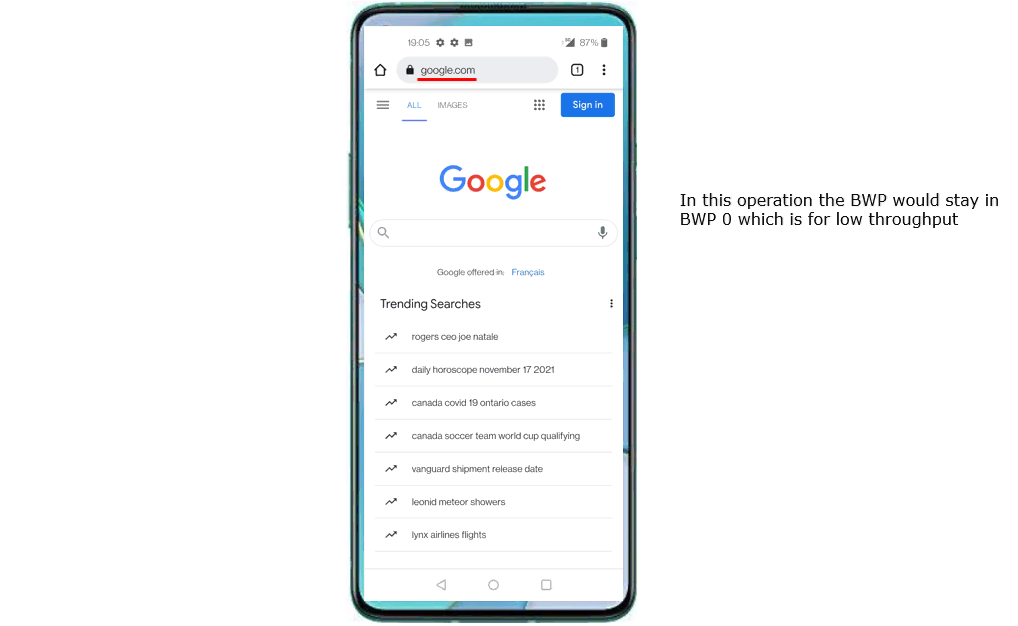
Try Browsing and make it sure that internet access works. Launch any type of browser app on your mobile phone and visit to any known sites (e.g, www.google.com) and see if it works.
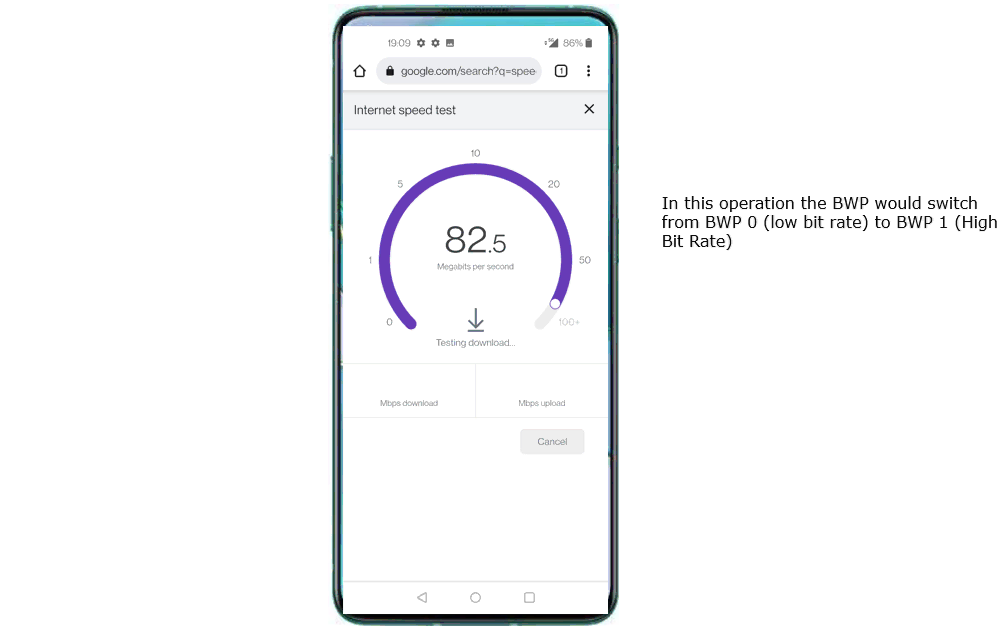
Go to speedtest site and generate high data rate of traffic. There are various different sites for the speedtest and you can use any of them as you like.
Log Analysis
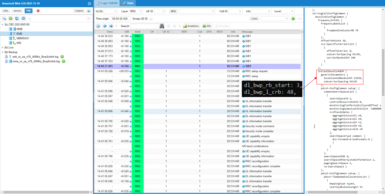
First check out initial BWP configuration in SIB1 and see if the message is set as you configured in the configuration file.
initialDownlinkBWP in SIB1 should be configured as you set in dl_bwp_rb_start and dl_bwp_l_crb for DL BWP 0 in the configuration file.
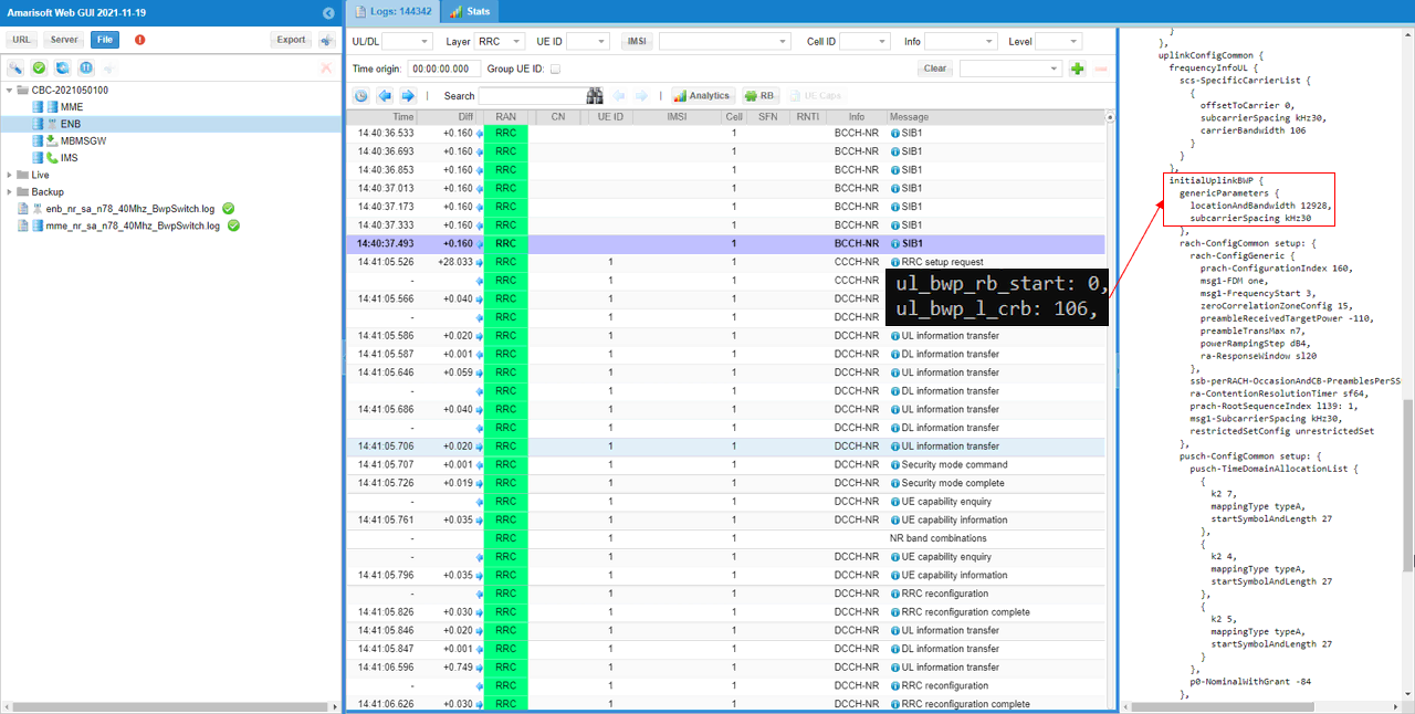
initialUplinkBWP in SIB1 should be configured as you set in ul_bwp_rb_start and ul_bwp_l_crb for UL BWP 0 in the configuration file.
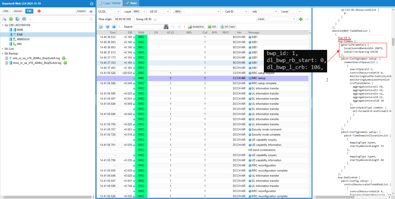
BWPs other than initial BWP are usually configured in RRC Setup.
DL bwp 1 within downlinklinkBWP-ToAddModList in RRC Setup should be configured as you set in bwp_id, dl_bwp_rb_start, dl_bwp_l_crb within dl_bwp block in the configuration file.
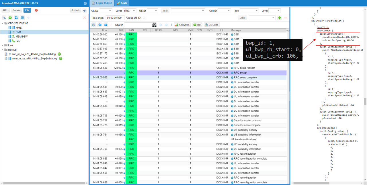
UL bwp 1 within uplinkBWP-ToAddModList in RRC Setup should be configured as you set in bwp_id, ul_bwp_rb_start, ul_bwp_l_crb within ul_bwp block in the configuration file.
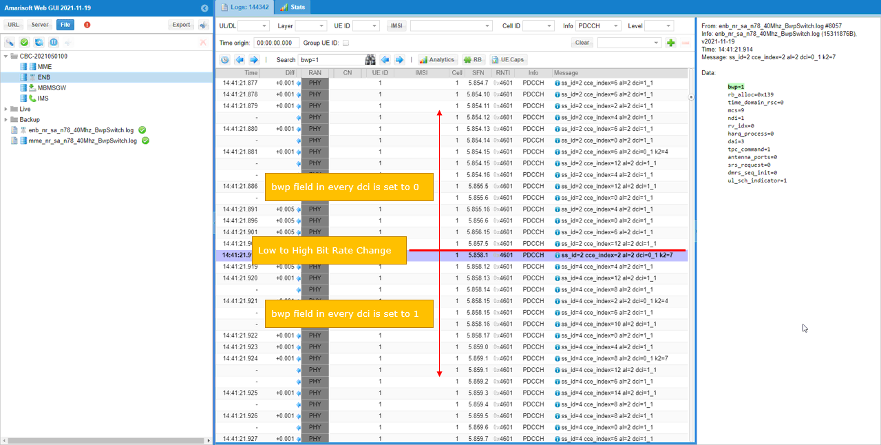
You can check on how BWP changes in low layer. Which BWP is in action can be confirmed by checking the bwp field in DCI 1_1 and DCI 0_1.
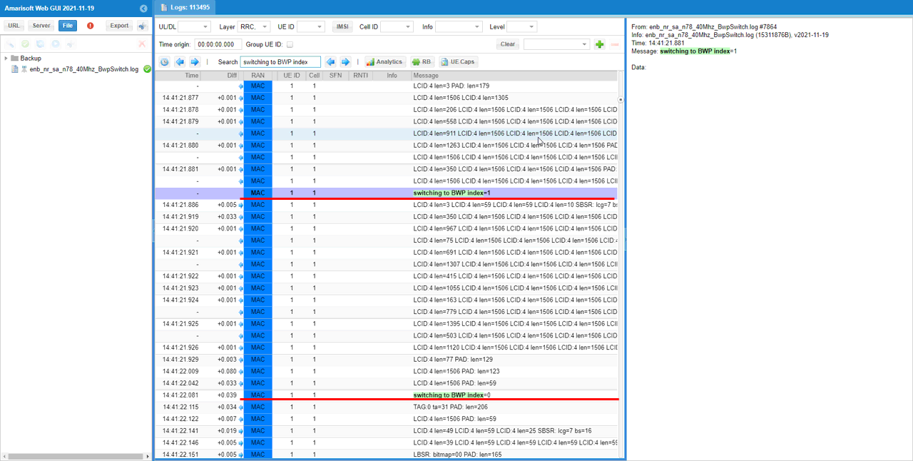
If you want to check if the bwp switching really happens, check if there is any point where bwp value changes in lower layer log. You may use 'Search' function in WebGUI to find those point easily.
An easier way to finding such a switching point is to check the high level description in Message column in the log. You can search the keywords 'switching to BWP index'.
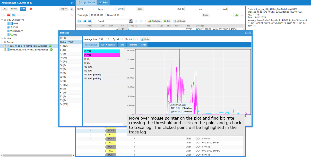
If you configure different sizes of physical resources among different bwp and running high enough user traffic, you should see traffic changes according to the corresponding bwp configuration. You can easily confirm on this with WebGUI throughput plot.
Test 2 : BWP Switching with Rrc Trigger
In this test, I will show you how to switch BWP via RRC message, namely RRC triggered BWP switching. This is splitted into two sub categories depending on how the RRC message for BWP switching gets triggered. There are two different way to let gNB to transmit the RRC message for bwp switching. One is throughput threshold and the other one is Remote API.
Configuration
You need to enable two configuration parameter rrc_based_bwp_switch and allow_rrc_bwp_switch. rrc_based_bwp_switch is a parameter for the dynamic BWP switch based on throughput and allow_rrc_bwp_switch is at cell level and creates the PUCCH resources so that RRC based BWP switch works well

Sub Test 1 : Throughput triggered RRC Transmission
Since this is to trigger RRC switch by throughput, you need to generate some IP traffic. In this tutorial, I generated the IP throughput from gNB to UE using ltesim_server .

Followings are some highlights from the log you may pay attention to.
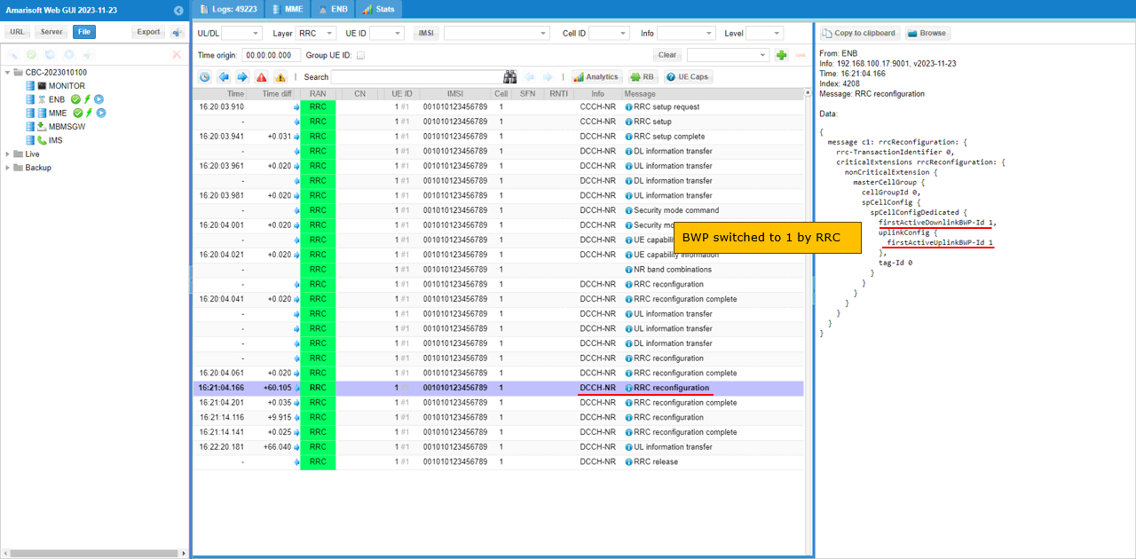
First check out which BWP are set as the active BWP before the switch. You can confirm on this by checking firstActiveDownlinkBWP-Id and firstActiveUplinkBWP-Id in RRC setup.
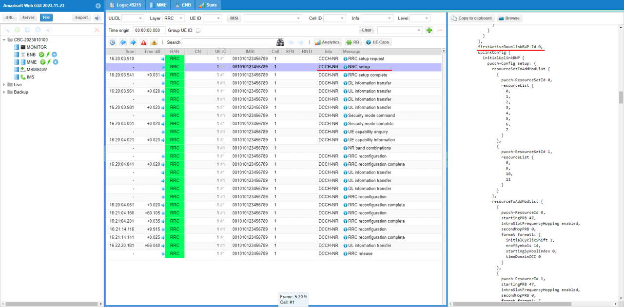
Now check if there is any RRC Reconfiguration message that set firstActiveDownlinkBWP-Id and firstActiveUplinkBWP-Id to target BWP id.
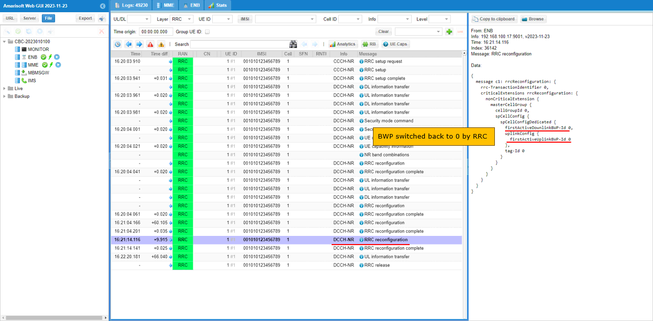
When the throughput gets lower again below the threshold you set in the configuration file, you should see another RRCReconfiguration with firstActiveDownlinkBWP-Id and firstActiveUplinkBWP-Id back to previous state.
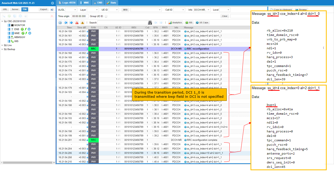
Now you can confirm the bwp switching at lower layer. As shown here, DCI type switches to DCI 1_0 in common search space during the transision period and then switched to DCI 1_1 with bwp=1 (target BWP) after RRC Configuration Complete message is recieved.
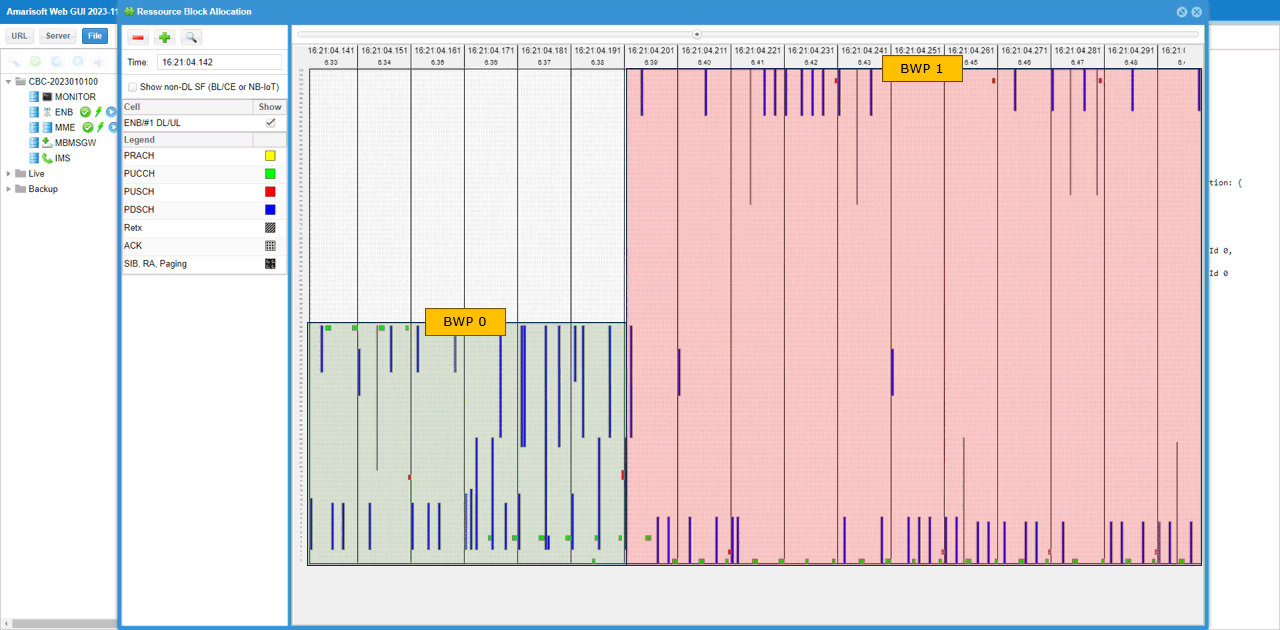
You can confirm on the BWP switching visually by checking out resource allocation in WebGUI. (
Sub Test 2 : RemoteAPI triggered RRC Transmission
You can use exact the same test setup and configuration file as in Test 1. The only difference is in how to trigger the switch. In this test, run the following RemoteAPI command (If you are not familiar with RemoteAPI, please go through the tutorial RemoteAPI first).
./ws.js enb '{"message":"rrc_cnx_reconf","enb_ue_id":1,"dl_bwp_id":1,"ul_bwp_id":1}'

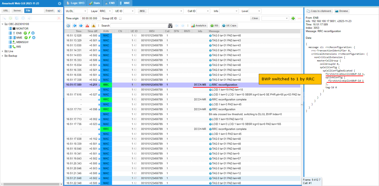
If the remoteAPI command is successfully processed, RrcReconfiguration for BWP switching is sent as shown below.
When the gNB received the remote API, you should see a RRCReconfiguration with firstActiveDownlinkBWP-Id and firstActiveUplinkBWP-Id switched to the destination BWP.
Test 3 : DCI-based Switch - UL Trigger
This test is for triggering BWP switching using DCI 0_1. The configuration is almost same as in Test 1 except the small changes as shown below. First, change is to add bwp_switch_k0 in pdsch : { } config. Actually this configuration is not requred for DCI 0_1, it is for DCI 1_1 triggering but I added this to use the same configuration file for both DCI 0_1 and DCI 1_1 triggering.

The second modification is to remove (comment out) bwp_dynamic_switch configuration from Test 1 configuration.

Now run the callbox and get UE attached. After the attach is complete and while the call is in connected state, run following RemoteAPI command. (NOTE : I would recommend you to do continous ping after attach so that the call status remain in connected mode).
./ws.js enb '{"message":"dci_bwp_switch","enb_ue_id":1,"ul_bwp_id":1}'

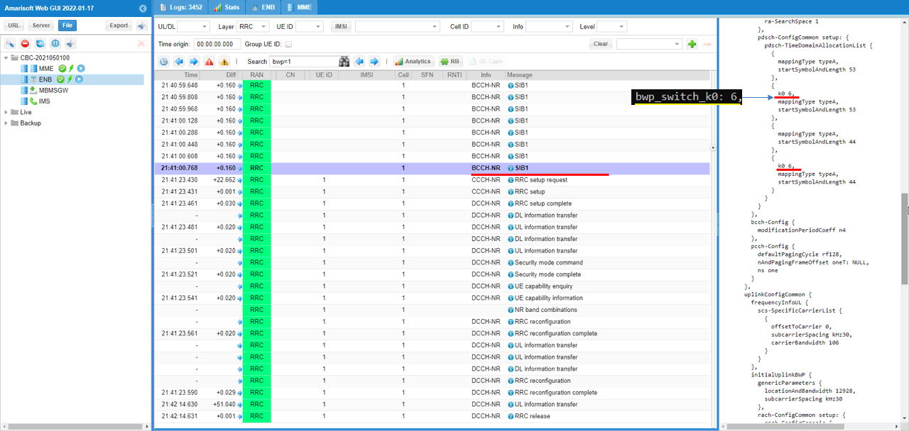
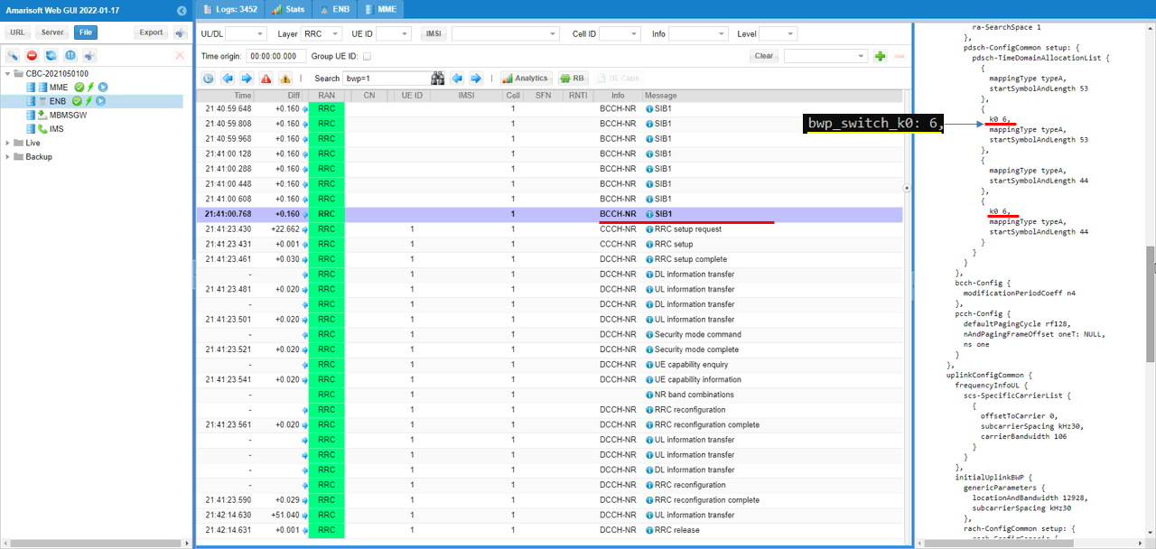
pdsch-TimeDomainAllocationList is modified by bwp_switch_k0 as shown below. Here you see that a couple of pdsch-ConfigCommon items which are set to be non-zero values.
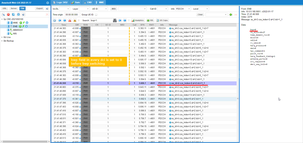
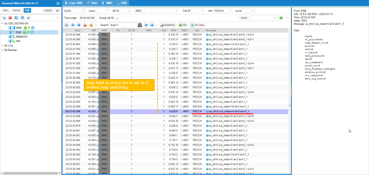
Before the BWP switching, all the bwp in DCI is set to 0 as shown below.
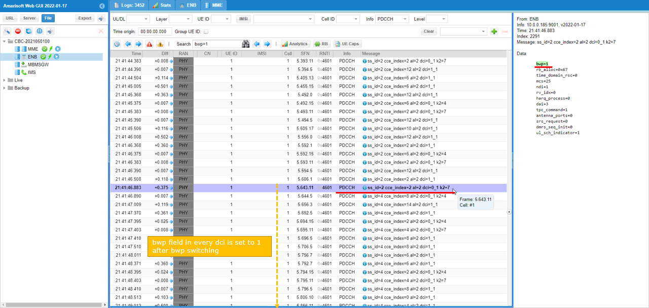
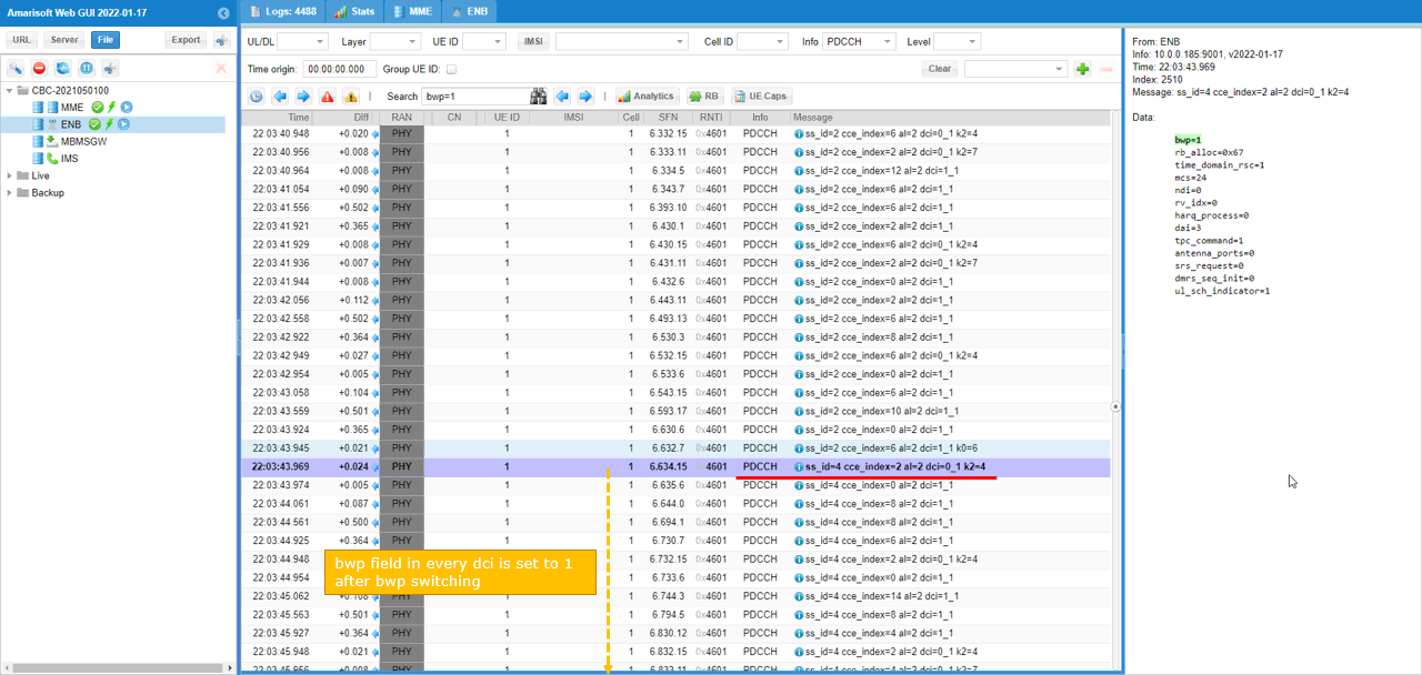
Before the BWP switching, all the bwp in DCI is set to 1 as shown below.
Test 4 : DCI-based Switch - DL Trigger
This test is for triggering BWP switching using DCI 0_1. The configuration is almost same as in Test 1 except the small changes as shown below. First change is to add bwp_switch_k0 in pdsch : { } config. Actually this configuration is not requred for DCI 0_1, it is for DCI 1_1 triggering but I added this to use the same configuration file for both DCI 0_1 and DCI 1_1 triggering.

The second modification is to remove (comment out) bwp_dynamic_switch part from Test 1 configuration.

Now run the callbox and get UE attached. After the attach is complete and while the call is in connected state, run following RemoteAPI command. (

pdsch-TimeDomainAllocationList is modified by bwp_switch_k0 as shown below. Here you see that a couple of pdsch-ConfigCommon items which are set to be non-zero values.
Before the BWP switching, all the bwp in DCI is set to 0 as shown below.
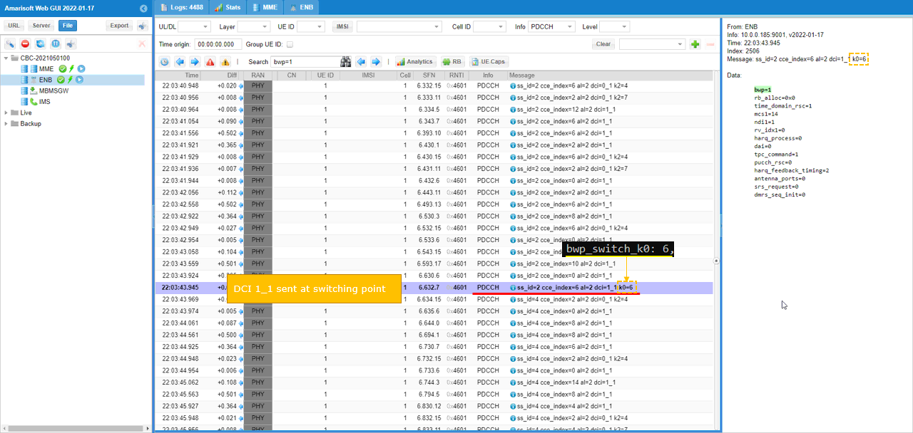
When BWP switching command is recieved, gnb send DCI 1_1 with k0 as epecified in bwp_switch_k0 parameter.
After BWP switching happened, all the bwp in DCI 0_1 and DCI 1_1 is set to 1
RRC / NAS Signaling
SIB1 (SA)
: This is the SIB1 message sent by gNB to configure NR SA. (
{
message c1: systemInformationBlockType1: {
...
servingCellConfigCommon {
downlinkConfigCommon {
frequencyInfoDL {
frequencyBandList {
{
freqBandIndicatorNR 78
}
},
...
},
initialDownlinkBWP {
genericParameters {
locationAndBandwidth 13750,
subcarrierSpacing kHz30
},
offsetToPointA 36,
scs-SpecificCarrierList {
{
offsetToCarrier 0,
subcarrierSpacing kHz30,
carrierBandwidth 51
}
}
},
uplinkConfigCommon {
frequencyInfoUL {
scs-SpecificCarrierList {
{
offsetToCarrier 0,
subcarrierSpacing kHz30,
carrierBandwidth 51
}
},
p-Max 10
},
initialUplinkBWP {
genericParameters {
locationAndBandwidth 13750,
subcarrierSpacing kHz30
},
}
RrcSetup (SA)
: This is the RrcSetup message sent by gNB to configure NR SA. (
message c1: rrcSetup: {
rrc-TransactionIdentifier 0,
criticalExtensions rrcSetup: {
...
masterCellGroup {
cellGroupId 0,
rlc-BearerToAddModList {
{
...
},
mac-CellGroupConfig {
...
},
physicalCellGroupConfig {
pdsch-HARQ-ACK-Codebook dynamic
},
spCellConfig {
spCellConfigDedicated {
initialDownlinkBWP {
pdcch-Config setup: {
...
},
pdsch-Config setup: {
...
}
},
downlinkBWP-ToAddModList {
{
bwp-Id 1,
bwp-Common {
genericParameters {
locationAndBandwidth 28875,
subcarrierSpacing kHz30
},
pdcch-ConfigCommon setup: {
...
},
pdsch-ConfigCommon setup: {
...
}
},
bwp-Dedicated {
pdcch-Config setup: {
...
},
pdsch-Config setup: {
...
}
}
}
},
firstActiveDownlinkBWP-Id 0,
uplinkConfig {
initialUplinkBWP {
pucch-Config setup: {
..
},
pusch-Config setup: {
...
},
srs-Config setup: {
srs-ResourceSetToAddModList {
...
}
}
},
uplinkBWP-ToAddModList {
{
bwp-Id 1,
bwp-Common {
genericParameters {
locationAndBandwidth 28875,
subcarrierSpacing kHz30
},
pusch-ConfigCommon setup: {
...
},
pucch-ConfigCommon setup: {
...
}
},
bwp-Dedicated {
pucch-Config setup: {
...
},
pusch-Config setup: {
...
},
srs-Config setup: {
...
}
}
}
},
firstActiveUplinkBWP-Id 0,
pusch-ServingCellConfig setup: {
}
},
pdcch-ServingCellConfig setup: {
},
pdsch-ServingCellConfig setup: {
nrofHARQ-ProcessesForPDSCH n16
},
Limitations
If you see the document, you may find some of the parameters/configurations are labeled as 'Experimental'. It may imply that the detailed implementation may not match what you expected. You may call them as a kind of limitation, but most of the limitation comes from unclear statement in 3GPP specification. The implmentation will be revised / updated as 3gpp specification gets updated and clearer.
RRC Based Switching
RRC based BWP switching is still experimental, mainly because 3GPP specification is not really clear about it:
Concerning the PDCCH, the search space displayed in the log at the point of BWP switching is the common search space (it is not the search space belonging to any specific bwp), and that search space should be shared among all other BWP. It uses physical resources of the CoReSet 0.
Concerning the PUCCH used for A/N feedback, the eNB indeed expects it on the 'new' BWP because it considers that the UE has time to process the RRCReconfiguration before sending it, and the 3GPP specification 38.331 and 38.321 hints that BWP switch is immediate upon RRC Reconfiguration :
From 38.331 - 5.3.5.5.7 :
consider the bandwidth part indicated in firstActiveUplinkBWP-Id if configured to be the active uplink bandwidth part;
From 38.321 - 5.15.1 :
For each activated Serving Cell configured with a BWP, the MAC entity shall:
1> if a BWP is activated and the active DL BWP for the Serving Cell is not the dormant BWP:
[...]
2>transmit PUCCH on the BWP, if configured
Due to this ambiguity, there might be the case where it looks as if some message (RRC message directing the switching) , HARQ ack/nack) goes through wrong bwp. But it is not the case. It would be the matter of interpretation. Since those messages are going through the common search space linked to CoreSet 0, it looks as if it belong to any bwp.
Search Space Selection During Switching
The eNB always use the common search space for 'major' reconfiguration (and BWP switch is one of those).
Since the eNB has no way to know when the UE actually applies the configuration change until the reception of the RRC Reconfiguration Complete and during that time, the User specific search space is not safe.
In order to still be able to schedule the UE without risk, the eNB uses the Common search space. Per our understanding, scheduling on the common search space is always allowed by 3GPP so it shouldn't cause any issue.
UL Resource Allocation Not Changing after Switch
Sometimes you may see UL resource allocated in much smaller region than is configured in configuration file and in Rrc message. You may often see this issue when you switch from a narrow BWP0 to wider BWPn as shown in the following example.
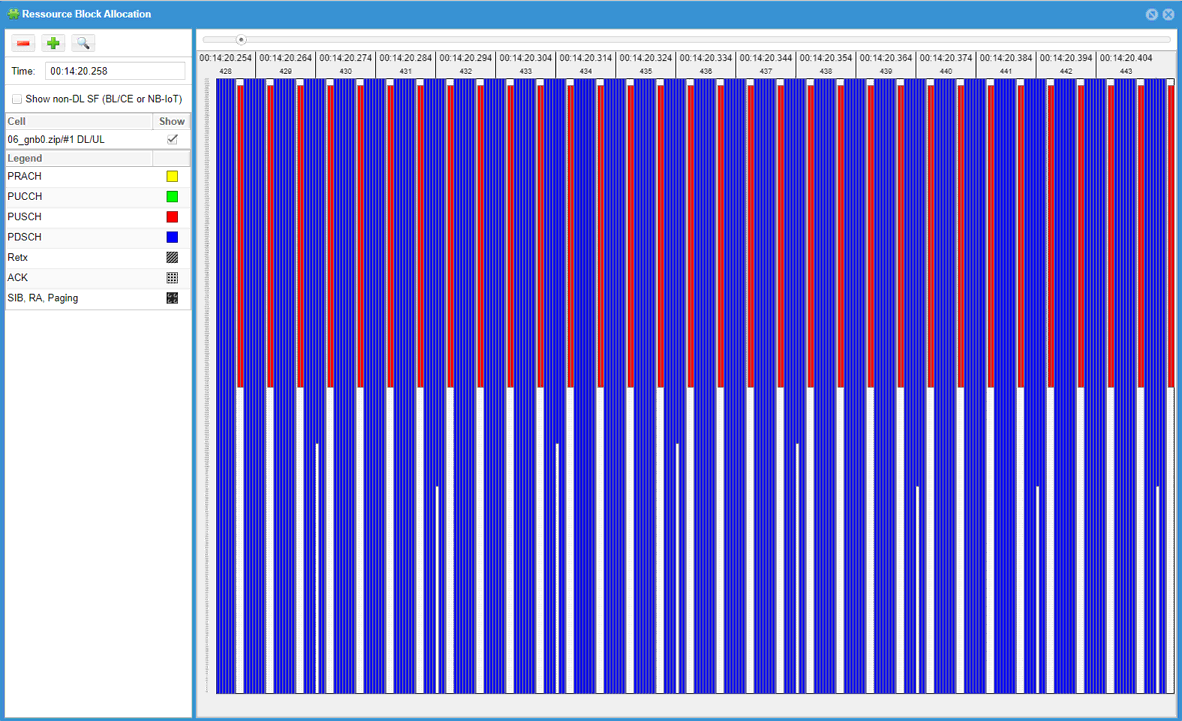
This is due to 3GPP ambiguity regarding frequency hopping requirement of Common PUCCH. You may look into and compare PUCCH resource allocation for initial BWP and BWPn if you want to know further. To workaround this, you may change ra_type configuration for BWPn as shown below
ul_bwp: [
{
bwp_id: 1,
ul_bwp_rb_start: 0,
ul_bwp_l_crb: 273,
pucch: {
},
pusch: {
beta_offset_ack_index: 9,
dmrs_add_pos: 1,
dmrs_type: 1,
dmrs_max_len: 1,
tf_precoding: false,
mcs_table: qam64,
mcs_table_tp: qam64,
msg3_mcs: 4
}
}
],
Tips
Remove Warnings
Sometimes you may have some warning printed out on callbox screen (lte screen window) when you run with your configuration. Since it is (warning), it would not block the operation and still valid configuration in terms of 3GPP. But the connection may not be stable and even fail in applying the Rrc with the bwp configuration depending on UE implementation. So I would suggest to remove those warnings as much as possible. In this section, I would give you some tips on the meaning of these warnings and how to remove it.
CoReSet #0 not inside DL BWP #n
For stable operation of BWP, it is recommended for every DL BWP to include CoReSet0 in it. If you set BWP frequency region that does not include CoReSet0 frequency region, you will get this warning.
How to fix it ?
Open up gnb log in a text editor and you will see the information like following at the beginning of the file.
coreset0_prb=start_rb : n_rb ==> this indicates coreset0 occupies the rb between start_rb and (start_rb + n_rb - 1)
Make it sure that you assigned prb region for every BWP to include this PRB region in it.
for smooth SA RRC BWP switching, UL BWP #n must contain UL BWP #0
This suggest to configure every UL BWP to include UL BWP #0. Without removing this, initial attach to BWP 0 would work OK without problem, but the connection would not stable (or break in worst case) when you switch bwp from bwp0 to other bwp.
For example, if your UL PWP 0 as follows.
ul_bwp_rb_start: start_rb,
ul_bwp_l_crb: n_rb,
Configure rb region for UL BWP#n (Other UL BWPs) as follows :
ul_bwp_rb_start (for BWP#n) <= start_rb -----> let's call this start_rb_n
ul_bwp_l_crb (for BWP#n) >= (start_rb + n_rb) - start_rb_n
unused property
This is not only for BWP configuration, but applies to every configuration. If you see this warning, it is likely to be due to one of the following reason.
- The parameter is not supported by the callbox software
- The parameter is supported but it is configured in wrong place (check out enb.doc for the details)