NR SA Power Control
This tutorial is about how to configure UL power control parameter and verify whether the power control works. The type of power control being configured in this tutorial is for closed loop power control. The way this power control works with Amarisoft gNB is as follows.
Step 1 : Configures snr target for pucch using the parameter dpc_snr_target in pucch: { } object
Step 2 : Configures snr target for pusch using the parameter dpc_snr_target in pusch: { } object
Step 3 : While UE is in Connected Mode, gNB measure snr for PUCCH and PUSCH. If the measured value is lower than dpc_snr_target for each channel. It sends TPC UP in DCI 1_x (for PUCCH) or DCI 0_x (for PUSCH).
Table of Contents
Introduction
Uplink (UL) power control is a critical aspect of radio access network configuration, ensuring optimal transmission power from user equipment (UE) to the base station (gNB) to maintain link quality, minimize interference, and optimize overall system performance. In 5G and advanced LTE networks, closed loop power control mechanisms dynamically adjust UE transmit power based on real-time measurements and feedback, allowing adaptation to varying radio conditions. Amarisoft gNB provides a flexible software environment for experimenting with and configuring these power control parameters, specifically through the adjustment of SNR (Signal-to-Noise Ratio) targets for Physical Uplink Control Channel (PUCCH) and Physical Uplink Shared Channel (PUSCH). By setting these targets, the gNB can instruct the UE to increase or decrease its transmit power via Transmit Power Control (TPC) commands embedded in Downlink Control Information (DCI) messages. This process is integral to maintaining reliable uplink communication, particularly in dense deployments or challenging RF environments. Understanding and effectively configuring UL power control is essential for network engineers and researchers aiming to fine-tune network performance, troubleshoot uplink issues, or explore the behavior of power control algorithms in a controlled testbed.
-
Context of Uplink Power Control in Cellular Networks
- UL power control regulates the transmit power of UEs to achieve a balance between adequate signal quality at the receiver (gNB) and minimal interference to neighboring cells.
- Closed loop power control allows dynamic, real-time adjustments based on feedback from the gNB, supplementing open loop techniques that rely on pre-configured parameters and pathloss estimates.
- In Amarisoft gNB, SNR targets for PUCCH and PUSCH channels are set using configurable parameters, enabling fine-grained control of power control behavior during live sessions.
-
Relevance and Importance of This Tutorial
- Correct UL power control configuration is crucial for maintaining uplink reliability, maximizing throughput, and reducing interference.
- This tutorial demonstrates the practical steps and considerations for configuring closed loop power control in Amarisoft gNB, which is widely used in research, development, and testing scenarios.
- By understanding these mechanisms, learners can troubleshoot uplink power issues and assess the impact of power control settings on network performance.
-
Learning Outcomes
- Gain hands-on experience configuring SNR targets for PUCCH and PUSCH to influence closed loop power control behavior.
- Understand the signaling flow and feedback mechanisms involved in TPC command generation and transmission.
- Acquire the ability to verify and interpret the effects of configured power control parameters on UE transmit power.
- Develop troubleshooting skills for common issues related to uplink power control in the Amarisoft environment.
-
Prerequisite Knowledge and Skills
- Familiarity with cellular network architecture, especially 5G NR and LTE uplink channels (PUCCH, PUSCH).
- Basic understanding of radio resource management concepts such as SNR, TPC, and DCI.
- Experience with Amarisoft Callbox or similar software-defined radio platforms is recommended.
- Ability to interpret and modify configuration files relevant to Amarisoft gNB operation.
Summary of the Tutorial
This tutorial outlines the procedures for testing Uplink Power Control in a 5G NR Standalone (SA) setup using a callbox and UE. The focus is on validating the power control mechanism for PUCCH and PUSCH channels based on SNR thresholds configured at the gNB.
- Test Setup:
- Utilizes a SIM card supplied with the system.
- Low layer testing environment—no complex IP setup required.
- For configuration changes, refer to the Configuration Guide.
- Key Configuration Parameters:
- Critical parameters include pucch.dpc_snr_target and pusch.dpc_snr_target, configured independently to control UL power for PUCCH and PUSCH.
- The gNB monitors SNR for each channel. If SNR is below the configured threshold, TPC UP is sent via DCI; if above, TPC DOWN is sent.
- Configuration Steps:
- Use a modified configuration file (gnb-sa-powercontrol-cl.cfg) specifying desired SNR targets.
- Default MME and IMS configurations are used for the test.
- SNR thresholds (dpc_snr_target) are set for both PUCCH and PUSCH to independently trigger power control actions.
- Test Procedure:
- Verify cell configuration to ensure intended setup.
- Power on the UE and attach it to the network.
- Confirm successful attachment and assignment of IP address.
- Initiate a continuous ping from the callbox to the UE to generate consistent UL traffic, which exercises the power control mechanism.
- Adjust rx_gain to push the measured SNR below the configured threshold, observing the gNB’s power control response.
- Monitor SNR fluctuations; the SNR should briefly dip below the threshold and then recover as power control takes effect.
- Log Analysis:
- Review UL power profiles to identify points where SNR thresholds are met or crossed.
- Use the [Analysis] function to visualize SNR trends for specific UEs.
- Check the TPC plot to observe where and how TPC commands were issued. Select the specific UE for accurate plotting.
- Filter log channels (e.g., BCCH, CCCH, DCCH, PDCCH) to focus on TPC operations and DCI content.
- Interpret tpc_command values in DCI: 2 for “increase power”, 1 for “no change”, 0 for “decrease power”.
The methodology outlined ensures thorough validation of uplink power control by dynamically adjusting receiver gain and analyzing both real-time and logged data to confirm proper TPC operation based on SNR measurements.
Test Setup
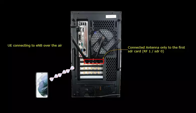
Test setup for this tutorial is as shown below. This is just for low layer testing, you may not need any complicated IP layer setup.
- SIM Card used in this tutorial is the one delivered with the system as it is.
- If you want to change the configuration, The tutorial Configuration Guide would help
Key Configuration Parameters
Followings are important configuration parameters for this tutorial. You may click on the items for the descriptions from Amarisoft documents.
- pucch
- pusch
Configuration
I have used gnb-sa-powercontrol-cl.cfg which is copied and modified from gnb-sa.cfg.
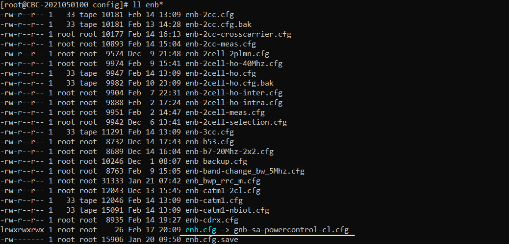
I am using the default mme (mme-ims.cfg), ims config as shown below.

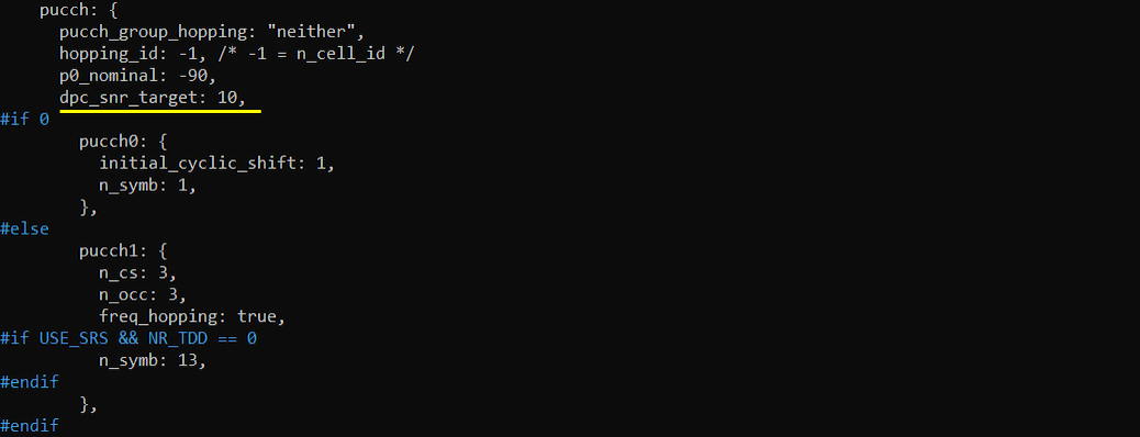
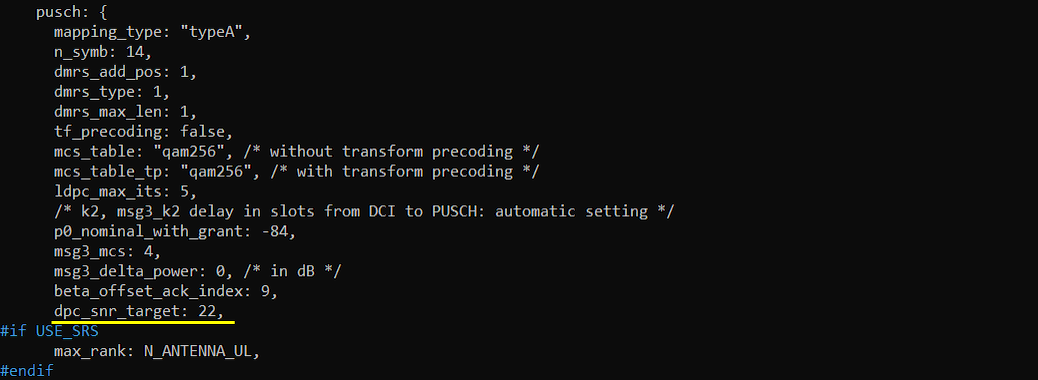
Following is the configuration in gnb-sa-powercontrol-cl.cfg. dpc_snr_target is the important parameter for UL power control. This parameter is configured separately for PUCCH and PUSCH so that we can set the criteria independently for PUSCH and PUCCH.
If PUCCH SNR estimated by gNB is lower than dpc_snr_target value, gNB send TPC UP via DCI and if the SNR is greater than the value, gNB send TPC down via DCI.

If PUSCH SNR estimated by gNB is lower than dpc_snr_target value, gNB send TPC UP via DCI and if the SNR is greater than the value, gNB send TPC down via DCI.
Perform the Test
Check the cell configuration and see if it is configured as intended.

Power on UE and get it attached.

Confirm that the attach is complete and UE get the IP address.

Try continuous ping from callbox to UE. Power Control is for Uplink channel power. So we need UE to generate UL channel traffic continuously. Ping would be the simplest way to do it.

Tweak rx_gain until it hits snr threshold that you specified in the configuration. Usually the snr would goes under the threshold temperarily and recover quickly as power control works.


Log Analysis
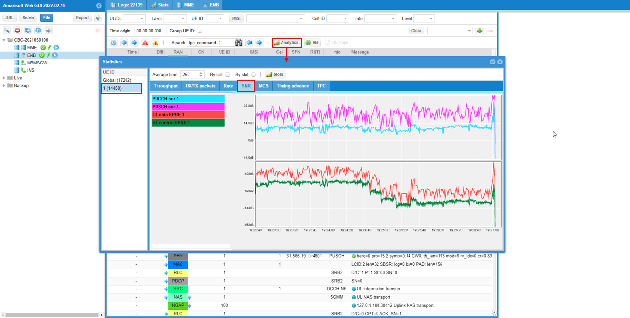
Check UL power profile and see if there is any points where the power control threshold are met. Hit [Analysis] button and then select [SNR] tab and pick the UE ID that you want to check.
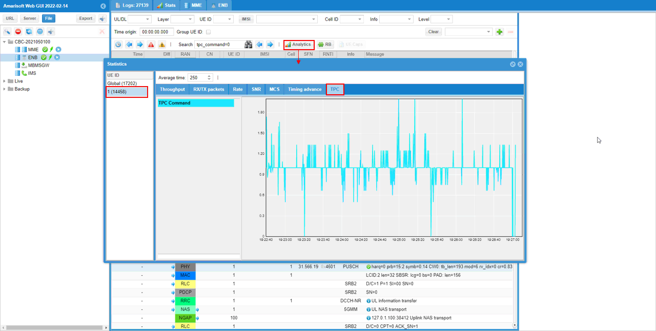
Check TPC plot and see if how much and where TPC comments were sent. For this plot, you need to select a specific UE in 'UE ID' pannel. 'Global' would not produce any plot.
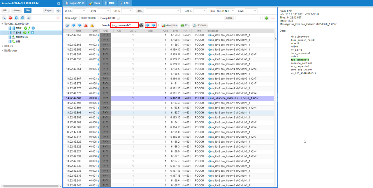
Filter the channels that help you check out TPC operation. I selected BCCH,CCCH,DCCH to display RRC message and selected PDCCH to check TPC value contained in DCI.
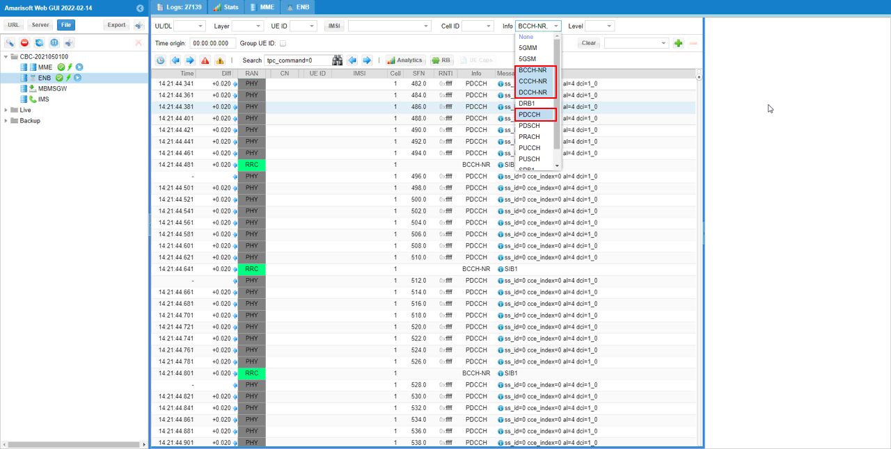
See if the tpc_comman field in DCI carries the proper values as you intended. tpc_command=2 indicates "increase the power", 1 indicates "stay same" and 0 indicates 'decrease the power'.
