NR SA D2C (Direct To Cell)
This tutorial is to show you how to configure and test Direct to Cell in NR. Direct to Cell represents 'From Satellite directly to Cellular Phone'. The 'Cellular Phone' in this context is just an ordinary commercial mobile hone that you have and it does not need to support any special feature for satellite communication as long as it works with ordinary NR SA in terrestrial network.
Actually Direct To Cell is not the 3GPP based feature like NTN (NB NTN or NR NTN). So the UE is not expected to support any specific features to accommodate this type of connection. So all the functionality to handle such a long delay or doppler shift etc which are present for satellite communication should be implemented by gNB that is sitting on the Satellite. This gNB implementation is mostly up to gNB vendor since the functionality is not specified in 3GPP.
Table of Contents
Introduction
Direct to Cell in NR (New Radio) is an innovative approach that enables ordinary commercial cellular phones to connect directly to a satellite, extending mobile coverage to remote and underserved regions without requiring specialized hardware or modifications on the user equipment (UE). This technology leverages the existing NR Standalone (SA) capabilities of standard smartphones, facilitating satellite-to-cellular connectivity without relying on traditional terrestrial infrastructure. Unlike 3GPP-standardized features such as NB-IoT NTN (Narrowband Internet of Things Non-Terrestrial Networks) or NR NTN (New Radio Non-Terrestrial Networks), Direct to Cell is not governed by formal 3GPP specifications. As a result, the mobile device operates as it would on a conventional terrestrial network, while all satellite-specific adaptations—such as compensating for extended signal propagation delay and managing Doppler shifts—are handled entirely by the gNB (next-generation NodeB) located onboard the satellite. The architectural distinction places significant responsibility on the satellite-based gNB, which must emulate terrestrial network behavior and ensure seamless interoperability for the UE. This paradigm allows mobile network operators and satellite providers to bridge connectivity gaps, offering ubiquitous coverage and supporting new use cases without imposing changes on end-user devices. The implementation details and optimizations for Direct to Cell are predominantly determined by the gNB vendor, given the absence of standardized protocols or message structures for this deployment model. As such, understanding the architectural requirements, technical considerations, and practical steps for configuring and testing Direct to Cell in NR is crucial for engineers and practitioners seeking to deploy or evaluate this emerging technology within the broader mobile ecosystem.
-
Context and Background
- Direct to Cell extends NR connectivity by allowing unmodified commercial handsets to connect directly to satellites, bypassing the need for terrestrial cell towers.
- Unlike standardized NTN solutions, Direct to Cell is implemented outside the 3GPP-defined feature set, placing customization responsibilities on satellite gNB vendors.
- The technology addresses coverage challenges in remote, rural, or disaster-affected areas where terrestrial infrastructure is unavailable or impractical.
-
Relevance and Importance
- Direct to Cell represents a significant advancement in bridging the digital divide, enabling global connectivity for standard mobile devices.
- It offers a cost-effective alternative to deploying terrestrial infrastructure, with potential applications in emergency communications, IoT, and expanding rural access.
- Understanding the configuration and testing process is essential for engineers, operators, and vendors aiming to leverage this technology in commercial deployments.
-
Tutorial Outcomes
- Learners will gain insight into the architectural and operational principles of Direct to Cell in NR.
- The tutorial will guide users through practical configuration steps and testing methodologies relevant to satellite-based NR deployments.
- Participants will develop a foundational understanding of the technical distinctions between Direct to Cell and standardized NTN solutions.
-
Prerequisite Knowledge
- Familiarity with 5G NR architecture and core concepts, including the roles of UE and gNB.
- Basic understanding of satellite communication challenges, such as signal delay and Doppler effects.
- Experience with NR SA (Standalone) network configurations and testing tools is beneficial.
Summary of the Tutorial
This tutorial details the setup and execution of low-layer Direct to Cell (D2C) testing using Amarisoft eNB and UEsim, focused on Simulated LEO satellite scenarios. The document emphasizes configuration, execution, and validation steps for D2C operation under NTN (Non-Terrestrial Networks) test profiles.
-
Test Setup Overview
- Uses a SIM card provided with the system; configuration changes are optional and referenced in a separate Configuration Guide.
- Test setup involves Amarisoft eNB (gNB) and UEsim, with focus on low-layer connectivity and not requiring complex IP configurations.
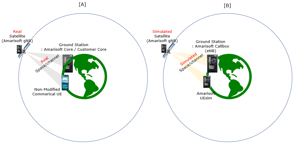
- Two possible hardware setups are referenced; the tutorial is based on the configuration indicated as [B] in the overview diagram.
-
Key Configuration Parameters
- The tutorial highlights the importance of a set of NTN-related configuration parameters in the Amarisoft system. These include satellite state vectors, ephemeris (orbital elements), ground station and UE positions, synchronization, frequency settings, direct_to_cell flag, and channel simulation controls, among others.
- Parameters such as ntn, default_ephemeris, ground_position, direct_to_cell, and channel_sim_control play a central role in modeling the satellite scenario.
-
Test 1: Direct to Cell with Simulated LEO and UEsim
- Objective: Configure and validate D2C operation with Amarisoft UEsim as the DUT (Device Under Test) under simulated LEO satellite conditions.
-
Configuration Steps:
-
Use gnb-sa-direct-to-cell.cfg for gNB configuration.
- Specify satellite orbit via NTN_MODE (choosing GEO for the test, even though LEO is referenced in the objective).
- Enable and configure CHANNEL_SIM (awgn profile for link simulation).
- Configure NR FDD band, set ssb_period to a low value for improved UE timing estimation, and adjust parameters such as force_full_bsr and force_dl_schedule for test visualization.
- Adjust prach_config_index as needed for long-distance links.
- MAC/RRC timers (e.g., retx_bsr_timer, sr_prohibit_timer, t300, t310, t_PollRetransmit) are set based on satellite-ground RTT and orbit type.
- NTN-specific parameters configured for satellite ephemeris, ground station, UE positions, and set direct_to_cell to indicate D2C mode.
-
Use ue-nr-sa-fdd-10Mhz.cfg for UEsim configuration.
- This configuration is a copy of a default NR SA config, modified only for band and channel bandwidth to align with gNB frequency settings.
- No satellite-specific changes are required for UEsim, mirroring the D2C objective of supporting standard UEs.
-
Use gnb-sa-direct-to-cell.cfg for gNB configuration.
-
Test Execution Procedure:
- Start LTE service on callbox, verify cell configuration via cell phy and cell commands.
- Optionally, enable BCCH logging for SIB message capture at test initiation.
- Start trace logging.
- Power on UE on UEsim (or commercial UE if available).
- Allow DUT to complete initial attach; additional troubleshooting may be required for commercial UEs or real satellites.
- Verify data plane by generating traffic (e.g., ping) to confirm data connectivity.
-
Log Analysis and Validation:
- Monitor real-time positions of eNB and UE using the WebGUI [ENB] and [NTN] tabs.
- Track satellite elevation, distance, and connectivity status; connection is lost if satellite elevation becomes negative.
- Observe signaling sequences, throughput, SNR, and DL CQI to assess link quality and system performance.
- Inspect satellite position (elevation, azimuth) and timing advance (TA) values for expected dynamic behavior as satellite moves.
- Filter logs for NTN-related status and metrics; log collection for NTN must be enabled during simulation runs.
In summary, the tutorial provides a detailed step-by-step methodology for configuring and validating Direct to Cell scenarios using simulated satellite links, with a focus on correct parameterization, test execution, and result analysis using Amarisoft systems. Critical configuration and procedural steps are highlighted to ensure repeatability and effective troubleshooting.
Test Setup
Test setup for this tutorial is as shown below. This is just for low layer testing, you may not need any complicated IP layer setup.
- SIM Card used in this tutorial is the one delivered with the system as it is.
- If you want to change the configuration, The tutorial Configuration Guide would help
With Amarisoft eNB and UEsim, we can try with following two different setups.
In setup [A], the satellite is real and carries an Amarisoft gNB. The ground station runs the Amarisoft Core or a customer core. The UE is a non-modified commercial phone, and the space channel is the real one.
In setup [B], everything runs in the lab. The satellite is simulated by the Amarisoft gNB, and the ground station is an Amarisoft Callbox. The DUT is Amarisoft UEsim, and the space channel is simulated as well.
Key Configuration Parameters
Followings are important configuration parameters for this tutorial. You may click on the items for the descriptions from Amarisoft documents.
- ntn : In this link, you can find the descriptions for all the parameters below.
- ephemeris
- use_state_vectors
- eci_reference
- ground_position
- n_ta_common
- n_ta_drift
- n_ta_drift_var
- n_ta_common_offset
- feeder_doppler_compensation
- feeder_dl_freq
- feeder_ul_freq
- large_freq_shift
- direct_to_cell
- channel_sim_control
- type
- ue_position
- ue_doppler_shift
- ue_dl_freq
- ue_ul_freq
- feeder_doppler_shift
- ue_dl_attenuation
- ue_dl_gain_offset
- ul_sync_validity
- k_offset
- k_mac
- dynamic_k_offset
- reference_location
- t_service
- neighbour_cells
- rat_type
- t318
Test 1 : D2C with Simulated LEO and UEsim
This is to configure and test Direct to Cell for Simulated LEO using Amarisoft UEsim as DUT.
Configuration
The configuration shown here is common configuration for all the subtests belonging to Test 1
I have used gnb-sa-direct-to-cell.cfg for gNB.
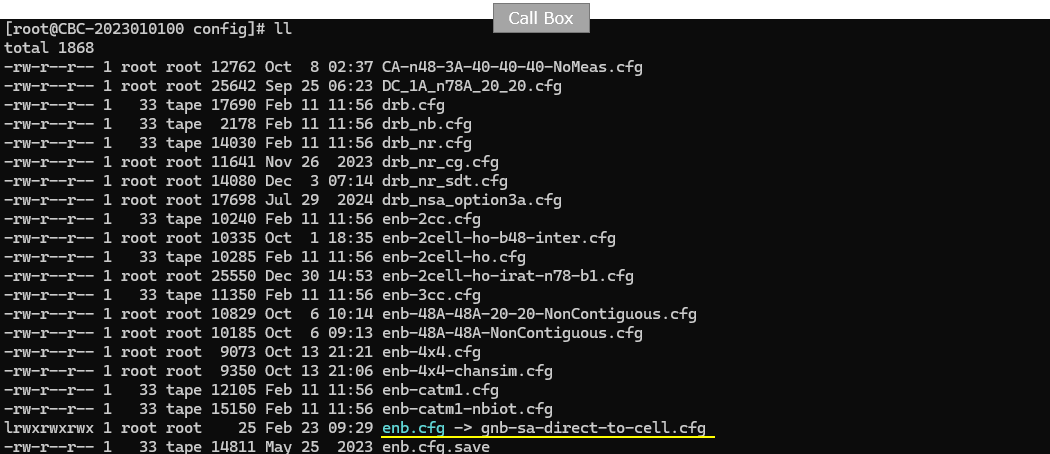
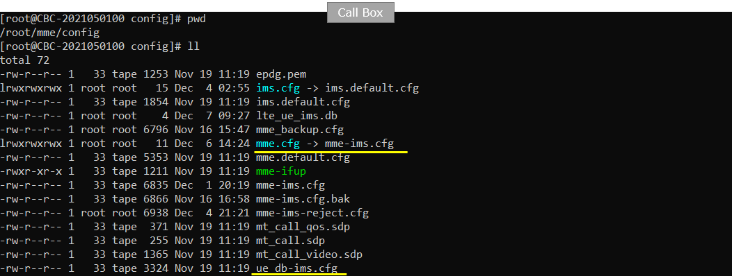
I am using mme-ims.cfg and ue_db-ims.cfg as they are.
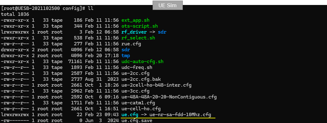
On UEsim, I used ue-nr-sa-fdd-10Mhz.cfg which is copied and modified from ue-nr-sa.cfg
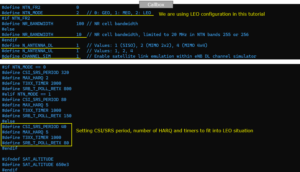
gnb-sa-direct-to-cell.cfg is configured as follows.
In gNB configruation, specify satellite orbit first with the test parameter NTN_MODE. You can select the type among GEO, MEO, LEO. In this test, GEO is selected. Once this parameter (NTN_MODE) is specified, various other test parameters are configured based on the selected NTN_MODE. (
In this file NTN_MODE is set to 2, so I am using the LEO configuration. NTN_FR2 is 0 and NR_BANDWIDTH is 10 MHz. N_ANTENNA_DL and N_ANTENNA_UL are both 1. CHANNEL_SIM is 1. That enables the satellite link emulation within the eNB DL channel simulator.
NTN_MODE selects one of three blocks. For LEO, the else branch sets CSI_SRS_PERIOD 40, MAX_HARQ 5, T3XX_TIMER 1000 and SRB_T_POLL_RETX 80. These fit the CSI/SRS period, the HARQ setting and the timers to the LEO situation. The GEO and MEO branches are not used in this test. SAT_ALTITUDE defaults to 650e3, that is 650 km.
If CHANNEL_SIM is enabled, you can apply various channel profile to simulate the radio link between ground station and satellite. In this test, only awgn is applied.
Under #if CHANNEL_SIM, the channel_dl of rf_ports uses type "awgn" with noise_level -50. You need to enable the channel simulator to emulate the radio link between the ground and the satellite.

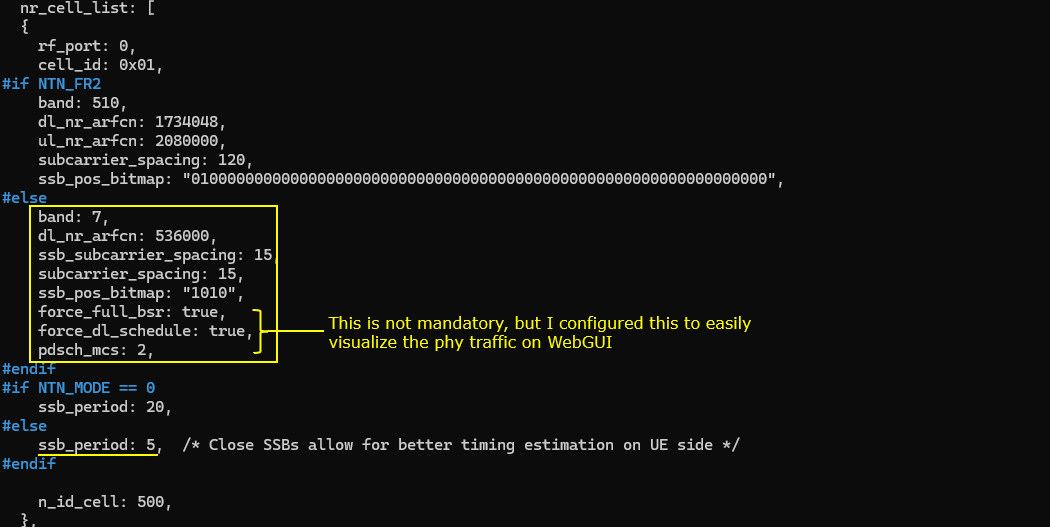
An NR FDD band is configured for this tutorial. And note that ssb_period is set to very small number (short period) to help UE get better timing estimation. In addition, just to help visualization of the test result, I set force_full_bsr, force_dl_schedule to true.
The NTN_FR2 branch with band 510 is not used here. The FDD branch sets band 7 and dl_nr_arfcn 536000, with ssb_subcarrier_spacing and subcarrier_spacing 15. ssb_pos_bitmap is "1010". force_full_bsr and force_dl_schedule are true, and pdsch_mcs is 2. These three are not mandatory. I set them only to make the PHY traffic easy to see on the WebGUI.
ssb_period is 5 for LEO and MEO. Only the GEO branch would use 20. The close SSBs allow for better timing estimation on the UE side. n_id_cell is 500.
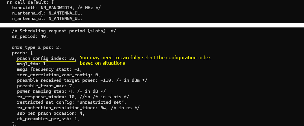
This may not be a mandatory but you may need to tweak prach_config_index to accommodate the long distance situation.
In nr_cell_default, bandwidth, n_antenna_dl and n_antenna_ul come from the defines, and sr_period is 40. The prach block uses prach_config_index 32. You may need to select this index carefully for your situation. The other prach values are msg1_fdm 1, ra_response_window 10, ssb_per_prach_occasion 4 and ra_contention_resolution_timer 64.
Now as MAC configuration, configure retx_bsr_timer, sr_prohibit_timer, prohibit_phr_timer, sr_trans_max differently based on the type of orbit. The basic idea is to configure these parameters differently based on RTT between the satellite and ground station.
In mac_config, ul_max_harq_tx and dl_max_harq_tx are 5. ul_max_consecutive_retx and dl_max_consecutive_retx are 30, and the UE is disconnected if they are reached. retx_bsr_timer is 320 and prohibit_phr_timer is 200.
time_alignment_tx_timer is 40, sr_prohibit_timer is 16 and sr_trans_max is 64. I set all of these to fit LEO. You may need to optimize them further depending on your situation.
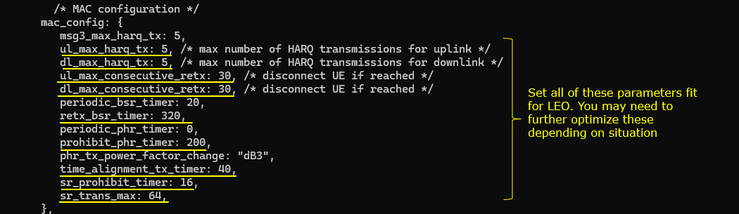
Then adjust RRC timers t300, t310 appropriately for each orbit type. And then adjust t_PollRetransmit based on the type of the orbit.
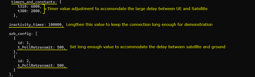
In timers_and_constants, t310 is 6000 and t300 is 2000. These values accommodate the large delay between the UE and the satellite. inactivity_timer is 100000. I made it long to keep the connection up for the demonstration.
In srb_config, both SRB 1 and SRB 2 use t_PollRetransmit 500. That is long enough for the delay between the satellite and the ground.
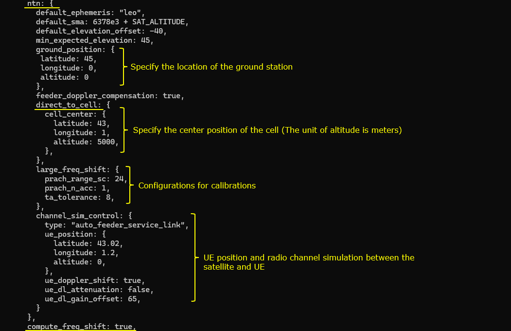
Now for the configurations specific for ntn. The configuration parameter name itself is ntn. In this parameter, you can specify the location of the satellite (i.e, the ephemeris), the location of ground station (i.e, the location of gNB) and ue location. The location of the ground station is specified by the parameter ground_position, the location of UE is specified by the parameter ue_position and the position of the satellite is specified by the parameter default_ephemeris. The parameter direct_to_cell indicates this is for Direct to Cell, not for NTN.
In ntn, default_ephemeris is "leo" and default_sma is 6378e3 + SAT_ALTITUDE. default_elevation_offset is -40 and min_expected_elevation is 45. ground_position puts the ground station at latitude 45, longitude 0 and altitude 0. feeder_doppler_compensation is true.
direct_to_cell holds cell_center at latitude 43, longitude 1 and altitude 5000. The unit of altitude is meters. large_freq_shift sets prach_range_sc 24, prach_n_acc 1 and ta_tolerance 8. These are for calibration.
channel_sim_control uses type "auto_feeder_service_link". Its ue_position puts the UE at latitude 43.02, longitude 1.2 and altitude 0, close to the cell center. ue_doppler_shift is true, ue_dl_attenuation is false and ue_dl_gain_offset is 65. After the ntn block, compute_freq_shift is set to true.
ue-nr-sa-fdd-10Mhz.cfg is configured as shown below. (
The key point here is that you don't need to configure any specific settings for satellite communication since Direct to Cell is designed to make Satellite communication possible with ordinary UE without any special modification. So in this tutorial, you will see all the configuration on UEsim remain same as in default configuration (ue-nr-sa.cfg) except band and channel bandwidth just to make it match gNB frequency settings.
The defines are N_ANTENNA_DL 1, TDD 0, FR2 0 and CELL_BANDWIDTH 10. They match the 10 MHz FDD cell with one DL antenna on the gNB.

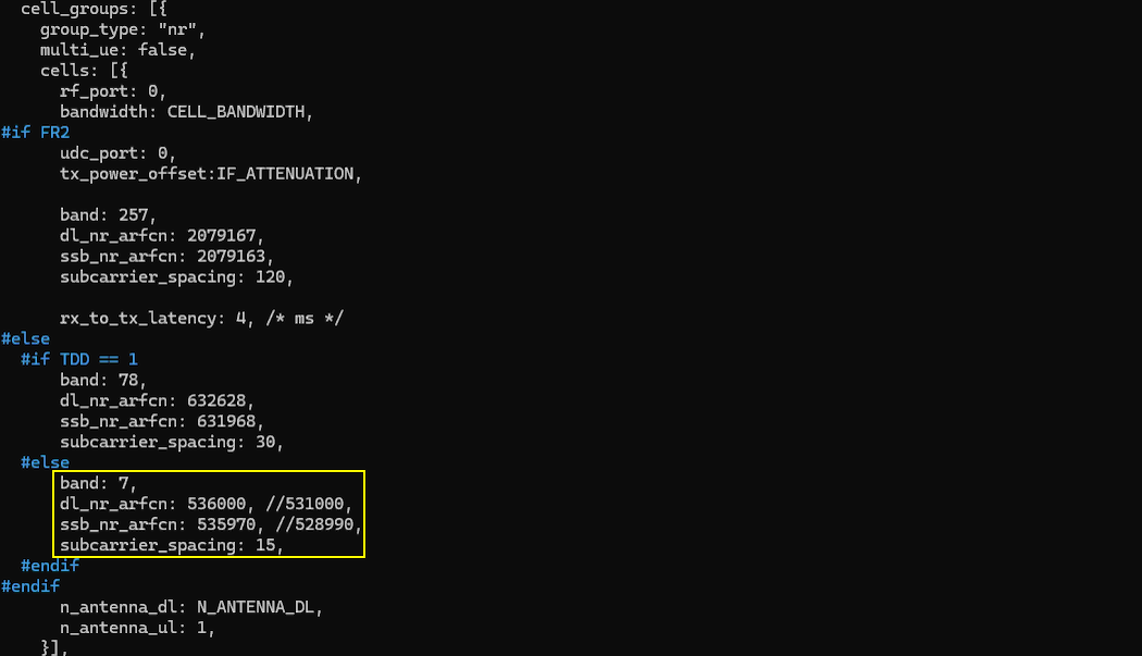
Only band and channel (dl_nr_arfcn, ssb_nr_arfcn) is changed to match gNB frequency and band settings.
In cell_groups, the FDD branch sets band 7, dl_nr_arfcn 536000, ssb_nr_arfcn 535970 and subcarrier_spacing 15. The FR2 and TDD branches are not used. n_antenna_dl takes N_ANTENNA_DL and n_antenna_ul is 1.
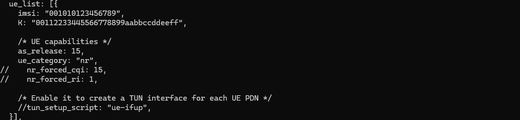
ue_list configuration is also set to be same as in default.
The UE has imsi 001010123456789, as_release 15 and ue_category "nr". nr_forced_cqi, nr_forced_ri and tun_setup_script stay commented out.
Perform the Test
Run lte service on callbox and then check 'cell phy' and 'cell' command. Make it sure that cell is configured as you intended. In this test, n7(FDD) is used
cell phy reports gNB_ID 0x12345 with PLMN 00101. Cell 0x001 is NR band n7 with BW 10, DL ARFCN 536000, UL ARFCN 512000 and SCS 15. It uses one antenna and one layer in each direction, and the SSB ARFCN is 535970. The cell command adds TAC 0x000064, pci 500 and prach_seq 12.

This is not the mandatory process.. but you may do this to collect SIB message in the log for a few seconds at the beginning. I did bcch=1 and after a few seconds did bcch=0.
log bcch=1 turns on the BCCH log, and log bcch=0 turns it off again.

Now start trace logging.
t starts the trace on the gNB console. Press return to stop it.

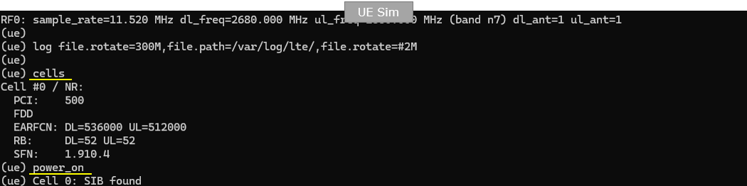
Power on UE on UEsim (If your DUT is a commercial phone, turn on the phone)
RF0 runs at sample_rate 11.520 MHz with dl_freq 2680.000 MHz in band n7. cells finds PCI 500, FDD, DL 536000 and UL 512000 with 52 RB. After power_on, the UE reports SIB found on cell 0.
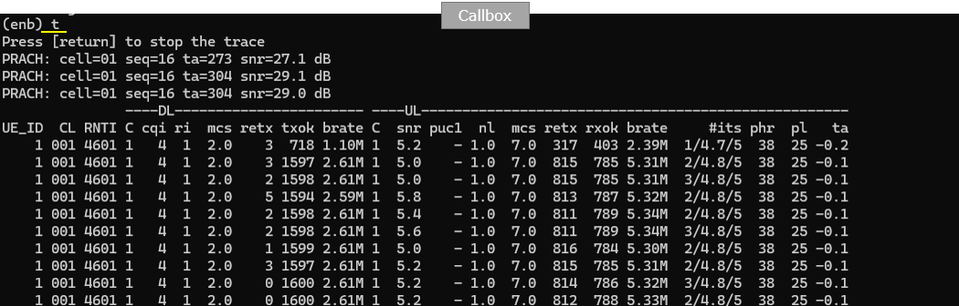
Wait until the DUT complete the initial attach. (
In the gNB trace, PRACH arrives on cell 01 with seq 16 and ta 273, then 304, at about 29 dB snr. UE 1 then runs on RNTI 4601. DL is at mcs 2.0 with brate about 2.61M. This mcs comes from pdsch_mcs 2 in the gNB configuration. UL is at mcs 7.0 with brate about 5.3M, snr about 5 dB and ta around -0.1.
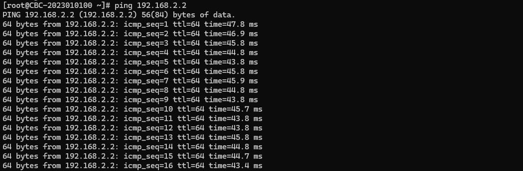
Try some data traffic (e.g, ping) to verify the data pipe setup.
The ping from the callbox goes to 192.168.2.2, the UE address. Every reply comes back, with time between 43.4 ms and 47.8 ms.
Log Analysis
Following is the log snapshot that are involved in communication with NTN.
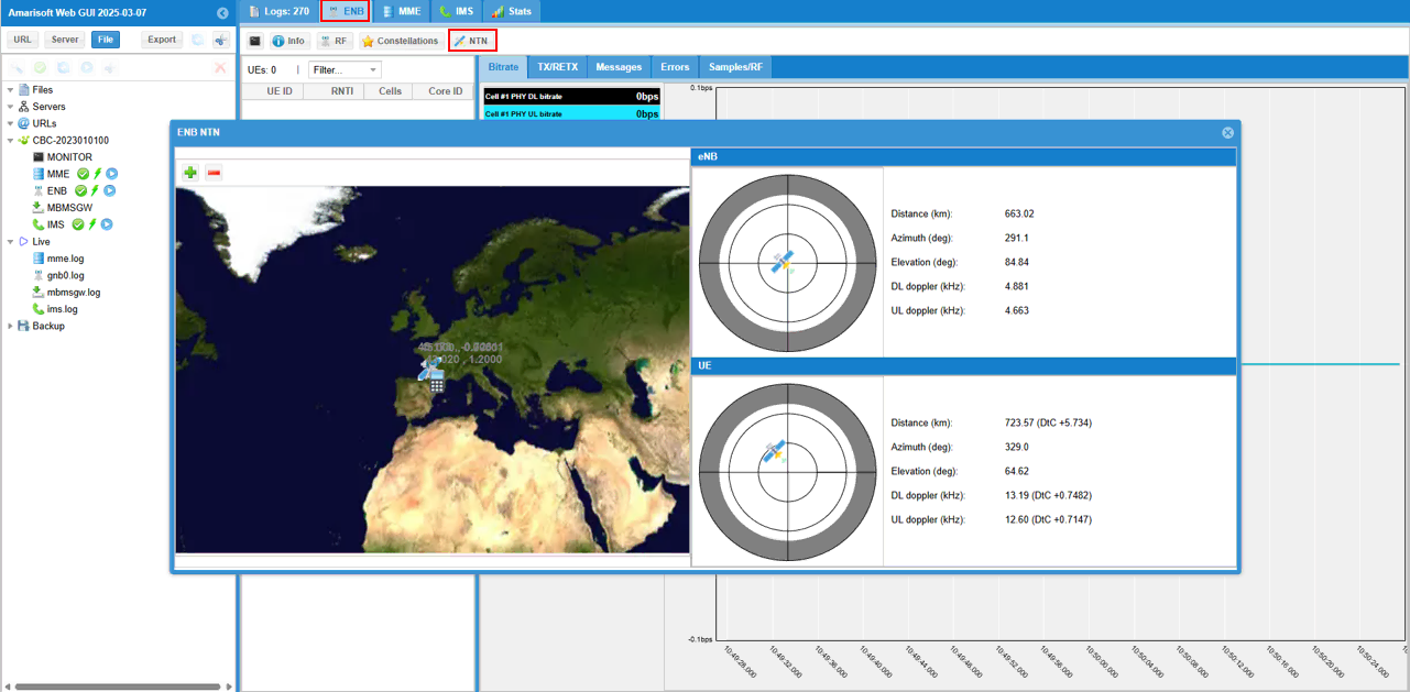
While the test is running, you can check out the position of eNB and UE in real time with WebGUI. While running, select [ENB] tab and hit [NTN] button and you see the view as shown below.
[eNB] pannel shows the sky view of eNB (sky view from eNB) and [UE] pannel shows the sky view of UE (sky view from UE). When the following value goes negative, satellite link gets disconnected since the satellite is not obserbable from UE.
- Elevation
- DtC value in Distance on UE pannel
In this run, the [eNB] panel gives a distance of 663.02 km, azimuth 291.1 and elevation 84.84 degrees. DL doppler is 4.881 kHz and UL doppler is 4.663 kHz.
The [UE] panel gives a distance of 723.57 km with DtC +5.734, azimuth 329.0 and elevation 64.62 degrees. DL doppler is 13.19 kHz (DtC +0.7482) and UL doppler is 12.60 kHz (DtC +0.7147). The elevation and the DtC distance value are both positive here, so the link is up.
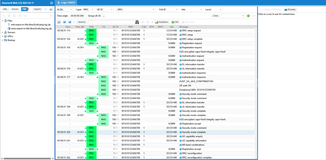
You may check out overall signaling sequence and details, in Direct to Cell there is no differences in signaling side from what you see regular communication (i.e, terrestrial communication)
The sequence is the usual NR SA one. RRC setup comes first, then registration, authentication and security mode command on the 5GMM NAS. UE capability enquiry and RRC reconfiguration follow. The UE has IMSI 001010123456789.
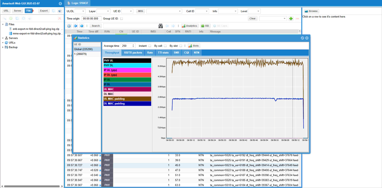
Check out throughput and see if you are getting expected throughput. In this test, I set force_full_bsr, force_dl_schedule to true. So you would get relatively high throughput at PHY,MAC.
The DL curve stays around 2.6 Mbps and the UL curve around 5 Mbps for the whole test. The legend marks them as DL MAC padding and UL MAC padding. The values match the brate in the gNB trace.
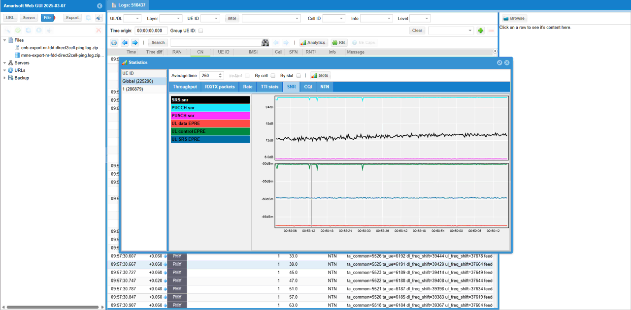
Then check SNR to check the radio link quality over the course of the test.
PUCCH snr stays around 25 dB and SRS snr around 12 dB. UL control EPRE is about -50 dBm and UL SRS EPRE about -60 dBm. The lines stay flat apart from a few short dips.
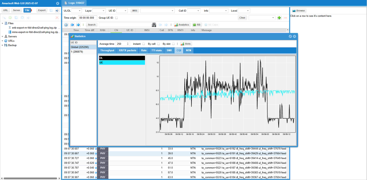
You can check out the signal quality percieved by UE from DL CQI plot
The UE CQI stays around 7 to 8 through the test. DL CQI starts around 4 and rises to between 6 and 12 in the middle of the test. It drops back to about 4 near the end.
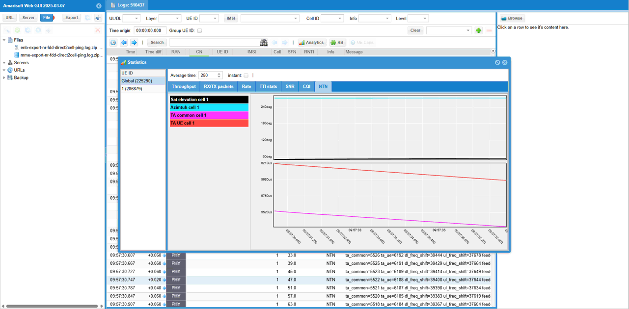
In [NTN] tab, you can check out Satellite position (Elevation and Azimuth) and Timing Advance command value.
The NTN tab plots Sat elevation, Azimuth, TA common and TA UE for cell 1. TA UE starts around 6210 us and TA common around 5520 us. Both decrease slowly while the satellite moves.
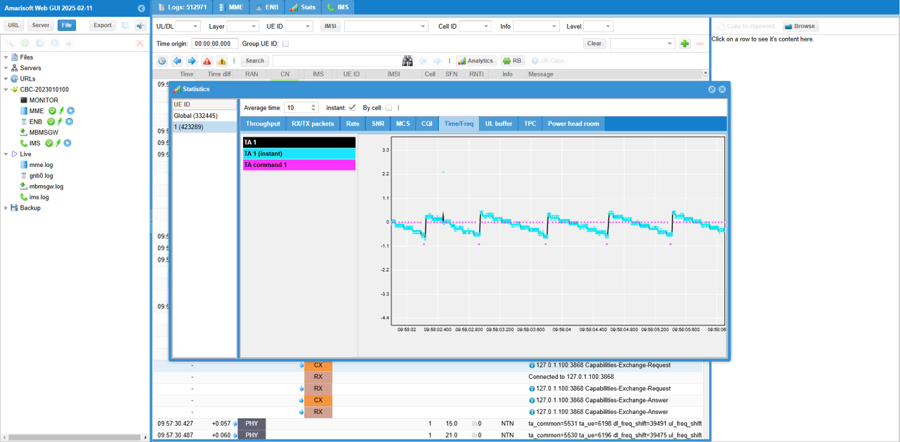
If you magnify TA command value in [Time/Freq] tab, you would see a pattern as shown below. When TA dropes below -0.5, we send a command to do TA +1 and it goes to +0.5 and then slowly decreases as the satellite moves
Each TA command 1 point lines up with one step of TA 1. Between the steps, TA 1 slides down slowly. The pattern repeats several times within a few seconds.
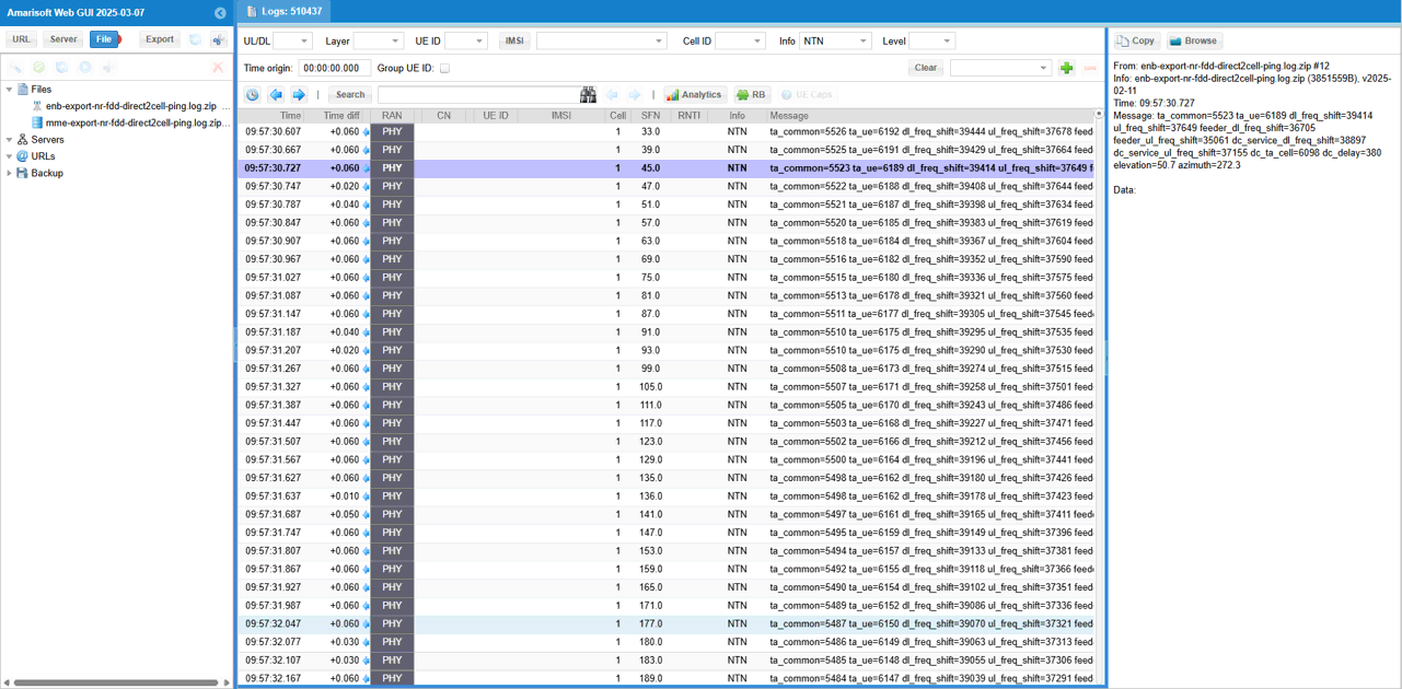
If you want the check all the NTN status in values, you may apply the filter 'NTN' in the info combo box. (
With the Info filter set to NTN, every PHY NTN line carries ta_common, ta_ue, dl_freq_shift and ul_freq_shift, plus the feeder values. The selected line has ta_common=5523 and ta_ue=6189. It also gives dc_service_dl_freq_shift=38897, dc_ta_cell=6098 and dc_delay=380, with elevation=50.7 and azimuth=272.3.