LTE NB NTN (Non Terrestrial Network)
This tutorial is to show you how to configure and test LTE NB NTN. NTN (Non Terrestrial Network) is a type of network deployment in which some type of non-terrestrial (e.g, satellite or other airborne component). Overall protocol sequence of NTN is not much different from the existing LTE RAN access (LTE NB, LTE, NR), but one major difference is to handle the long propagation delay between the ground components (eNB and/or DUT) and Satellite. There are two major components introduced in 3GPP as listed below.
- Additional SIBs : This is mainly to inform the position of Satellite (i.e, ephemeris) and default time delay. In LTE case, the SIB31 carries these information.
- Additional MAC CE : These are mainly to handle the long time delay. The MAC CE "Differential Koffset" is introduced for PDSCH and "Timing Advanced Report" for PUSCH.
There are various different type of NTN deployment in 3GPP TR 36.763. Currently Amarisoft NTN implementation is as shown below.

Table of Contents
- LTE NB NTN (Non Terrestrial Network)
- Introduction
- Summary of the Tutorial
- Test Setup
- Key Configuration Parameters
- Test 1 : NTN with Simulated GEO and UEsim
- Test 2 : NTN with Simulated GEO and Commercial UE in non-NTN band
- Test 3 : NTN with Simulated GEO and Commercial UE in NTN band
- Test 4 : NTN with Simulated LEO and Commercial UE in NTN band
- RRC / NAS Signaling
- FAQ
Introduction
LTE NB NTN (Narrowband Internet of Things for Non-Terrestrial Networks) is an advanced extension of the LTE (Long Term Evolution) architecture designed to enable reliable connectivity between terrestrial and non-terrestrial components, such as satellites or airborne platforms. As defined by 3GPP standards, NTN provides coverage in areas where traditional terrestrial networks are insufficient or unavailable, leveraging satellite-based communication to extend the reach of cellular IoT services. The key architectural enhancement in LTE NB NTN, compared to conventional LTE RAN (Radio Access Network) access, lies in its ability to manage the significantly longer propagation delays introduced by the satellite link between ground-based entities (such as eNBs and devices) and the non-terrestrial relay. To accommodate these unique challenges, the 3GPP architecture introduces additional System Information Blocks (SIBs)�"specifically SIB31 for ephemeris data and default delay parameters�"and specialized MAC Control Elements (MAC CEs) such as Differential Koffset and Timing Advance Report, which are essential for robust scheduling and synchronization over long-delay links. The technology is especially relevant for mission-critical IoT, remote monitoring, and global asset tracking scenarios, where persistent connectivity across vast and remote geographic regions is required. This tutorial focuses on the configuration and testing of LTE NB-based NTN, utilizing Amarisoft's implementation as per 3GPP TR 36.763, and highlights the unique deployment considerations, protocol adaptations, and operational recommendations necessary for successful NTN integration.
-
Context and Background
- LTE NB NTN integrates satellite or airborne network components with terrestrial LTE infrastructure, enabling IoT connectivity in remote and underserved regions.
- 3GPP introduced specific protocol adaptations for NTN, such as additional SIBs (notably SIB31) and MAC CEs, to address satellite communication challenges like long propagation delay and dynamic satellite positioning.
- The Amarisoft implementation referenced in this tutorial is based on 3GPP TR 36.763 and supports the latest protocol enhancements for LTE NB NTN as of the 2023-04-21 release.
-
Relevance and Importance
- NTN technology is vital for extending IoT and M2M (Machine-to-Machine) services to global, rural, and maritime environments where terrestrial networks cannot reach.
- Understanding and configuring LTE NB NTN is essential for network operators, engineers, and developers aiming to deploy commercial and mission-critical IoT solutions over satellite links.
- The tutorial addresses real-world deployment scenarios, protocol differences from conventional LTE, and practical considerations for long-delay link management.
-
Tutorial Learning Outcomes
- Gain a comprehensive understanding of LTE NB NTN architecture and the technical challenges of integrating non-terrestrial components.
- Learn how to configure Amarisoft-based LTE NB NTN setups, including SIB and MAC CE parameterization for satellite communication.
- Develop troubleshooting and testing skills for validating NTN deployments and ensuring robust, low-latency IoT connectivity over satellite links.
-
Prerequisite Knowledge and Skills
- Familiarity with LTE and LTE NB-IoT fundamentals, including protocol stack, RAN concepts, and system information broadcasting.
- Understanding of basic satellite communication principles, such as propagation delay and ephemeris data.
- Prior experience with Amarisoft LTE test environments is recommended for practical configuration and testing exercises.
- Access to hardware and software supporting at least the 2023-04-21 Amarisoft release is required for hands-on implementation.
Summary of the Tutorial
This tutorial outlines test procedures for evaluating NTN (Non-Terrestrial Network) functionality using Amarisoft eNB and UEsim, as well as commercial UEs. The procedures focus on low-layer testing, involving simulated GEO satellite scenarios and various UE configurations. Below is a summary of the main test setups and methodologies described in the tutorial.
-
Test Setup:
- Utilizes SIM cards provided with the system.
- Supports configuration changes via a separate Configuration Guide.
- Test configurations accommodate both Amarisoft UEsim and commercial UE devices.
- Key configuration parameters for the eNB and UE are detailed, including satellite ephemeris, ground position, doppler compensation, and channel simulation parameters.
-
Test 1: NTN with Simulated GEO and UEsim
- Configuration:
- Uses
enb-nbiot-ntn.cfg(from Amarisoft release 2023-04-21) for the eNB. - Uses
mme-ims.cfgandue_db-ims.cfgfor MME, as provided. - Configures UEsim with
ue-nbiot-ntn.cfgunless a commercial UE is used (in which case, ensure support for UE-assistance-information for release-preference). - Configuration screenshots demonstrate parameter setups for all nodes.
- Uses
- Test Execution Steps:
- Run LTE service on the callbox and verify cell status using the 'cell' command.
- Optionally enable BCCH logging for a few seconds to capture SIB messages, then disable it.
- Start trace logging on the callbox.
- Power on the UE (either UEsim or commercial device).
- Wait for the UE to complete initial attach to the network.
- Log Analysis:
- Analyze the collected logs to verify correct NTN signaling and attach procedures.
- Configuration:
-
Test 2: NTN with Simulated GEO and Commercial UE in non-NTN band
- Configuration:
- Uses
enb-nbiot-ntn-Quectel.cfgfor the eNB. - Uses
mme-ims.cfgandue_db-ims.cfgas provided for MME. - Configuration screenshots illustrate the required parameter settings.
- Uses
- Test Execution Steps:
- Run LTE service on the callbox and confirm 'cell' status.
- Optionally enable BCCH logging at startup to collect SIB messages, then disable it.
- Start trace logging.
- Configure the commercial DUT as required and power it on.
- Wait for the DUT to complete initial attach to the network.
- Log Analysis:
- Review log snapshots to confirm NTN-related procedures and successful network access.
- Configuration:
-
Test 3: NTN with Simulated GEO and Commercial UE in NTN band
- Device Info:
- Device: Quectel CC660D-LS with specific firmware versions detailed in the tutorial.
- Configuration:
- Uses
enb-nbiot-ntn-geo-CC660D.cfgfor the eNB. - Uses
mme-ims.cfgandue_db-ims.cfgas provided for MME. - Configuration screenshots provide guidance on required settings.
- Uses
- Test Execution Steps:
- Optionally enable BCCH logging for brief SIB message capture, then disable it.
- Start trace logging.
- Configure the DUT using AT commands (example sequences provided in the tutorial), including GNSS info and data session activation.
- Power on the DUT and wait for initial network attach and IP assignment.
- Log Analysis:
- Analyze trace logs to verify correct NTN signaling and attach behavior on the commercial UE.
- Device Info:
-
General Notes & FAQ Highlights:
- Channel simulator usage is essential for MEO/LEO scenarios due to larger delay and Doppler variation, and optional for GEO.
- The Amarisoft channel simulator supports delay simulation up to approximately 1118 seconds for NB-IoT (based on sample rate).
- Altitude parameters can be set from -1000m to 20km, allowing for locations below sea level.
The procedures focus on configuration, step-by-step execution, and post-test log analysis to confirm correct operation of NTN features under different simulated satellite conditions and UE types. Screenshots and AT command sequences are provided to guide actual setup and execution, ensuring repeatability and clarity for practitioners.
Test Setup
Test setup for this tutorial is as shown below. This is just for low layer testing, you may not need any complicated IP layer setup.
- SIM Card used in this tutorial is the one delivered with the system as it is.
- If you want to change the configuration, The tutorial Configuration Guide would help
With Amarisoft eNB and UEsim, we can try with following two different setups.

Key Configuration Parameters
Followings are important configuration parameters for this tutorial. You may click on the items for the descriptions from Amarisoft documents.
- ntn : In this link, you can find the descriptions for all the parameters below.
- ephemeris
- use_state_vectors
- eci_reference
- ground_position
- n_ta_common
- n_ta_drift
- n_ta_drift_var
- n_ta_common_offset
- feeder_doppler_compensation
- feeder_dl_freq
- feeder_ul_freq
- large_freq_shift
- direct_to_cell
- channel_sim_control
- type
- ue_position
- ue_doppler_shift
- ue_dl_freq
- ue_ul_freq
- feeder_doppler_shift
- ue_dl_attenuation
- ue_dl_gain_offset
- ul_sync_validity
- k_offset
- k_mac
- dynamic_k_offset
- reference_location
- t_service
- neighbour_cells
- rat_type
- t318
Test 1 : NTN with Simulated GEO and UEsim
Configuration
The configuration shown here is common configuration for all the subtests belonging to Test 1 and I will not show this configuration repeatedly for every subtest.
I have used enb-nbiot-ntn.cfg which is included in the installation package from the release 2023-04-21.

I am using mme-ims.cfg and ue_db-ims.cfg as they are.

On UEsim, I used ue-nbiot-ntn.cfg which is included in the installation package from the release 2023-04-21. (

For the UEsim, I used ue-nbiot-ntn.cfg which is copied and modified from ue-nbiot.cfg

enb-nbiot-ntn.cfg is configured as follows.
This configuration is a small NTN test-profile switch used for LTE/NB-IoT scenarios, where a single parameter selects the satellite orbit type and then drives a few dependent radio/protocol settings. By setting NTN_MODE you choose GEO, MEO, or LEO, and by setting CHANNEL_SIM you enable the internal link emulation so the "satellite" path can be reproduced in a controlled lab environment. Based on the selected orbit, the configuration then sets MAX_HARQ to an orbit-appropriate value, so the HARQ behavior is tuned to the expected propagation delay characteristics of GEO versus MEO/LEO.

This configuration enables the internal channel simulator so you can emulate the satellite-style radio link in a controlled lab setup, and it also adjusts the uplink timing reference used by the eNB/gNB when interpreting UE transmissions. When CHANNEL_SIM is enabled, the rf_ports section can attach a downlink channel model such as AWGN with a chosen noise_level, which is a simple and stable baseline before moving to more complex channel profiles. In addition, rx_ta_offset defines an optional uplink time offset in units of 1/1.92 �s; with a well-calibrated radio head where TRX timestamps already include internal hardware delays, this offset helps make the PRACH-derived timing advance for a UE close to the site come out correctly

This configuration shows the default NB-IoT cell system-information scheduling inside nb_cell_default, and it highlights that an NTN-oriented NB-IoT/LTE setup must explicitly schedule SIB31 so NTN-related information can be broadcast to the UE. The configuration enables per-SIB value tagging (si_value_tag_list_enable) and then defines the normal NB-IoT SI scheduling list (sib_sched_list) where files like sib2_nb.asn are transmitted with a given periodicity and repetition pattern, along with an si_value_tag used to indicate SI updates. In addition to the standard NB-IoT SIB scheduling, the block adds a dedicated sib31 configuration (with its own si_periodicity, si_repetition_pattern, and si_value_tag), which is called out as required to ensure the cell actually transmits the NTN-related broadcast information needed for LTE/NB NTN operation.

This ntn block is the core of the NTN-specific configuration that turns a normal cell into an NTN-aware cell by adding orbit context and geometry. At the top of the block, the configuration selects an orbit profile through default_ephemeris and pairs it with an ul_sync_validity value that reflects how long uplink timing and synchronization information can be considered valid for that orbit, with different values used for GEO, MEO, and LEO. The ground_position section then defines the geographic location of the ground station, meaning the site where the eNB/gNB is located, using latitude, longitude, and altitude. When CHANNEL_SIM is enabled, the channel_sim_control section activates a feeder/service link model and provides the UE position (ue_position) so the simulator can compute delay and Doppler more realistically; ue_doppler_shift: true further enables Doppler effects. A practical point is that when using Amarisoft UEsim, the UE position used here should match the UE-side position setting so both ends use consistent geometry for the NTN emulation.

Followings are the simplified configuration
|
/* Simplified NTN block (GEO + CHANNEL_SIM enabled, based on your earlier settings) */ ntn: { ul_sync_validity: 240, default_ephemeris: "geo",
ground_position: { latitude: 48.853, longitude: 2.348, altitude: 140 },
channel_sim_control: { type: "auto_feeder_service_link", ue_position: { latitude: 43.295, longitude: 5.373, altitude: 20 }, ue_doppler_shift: true } }, |
mme-ims.cfg is configured as follows :
This mme-ims.cfg fragment defines the PDN/APN profile that the core network will use when the UE requests data service, and it must match the APN name configured on the UE/UEsim side. In this example, the access_point_name is set to ntn-internet, the session type is ipv4v6, and the UE address pools are defined for both IPv4 and IPv6 by specifying the allocatable IPv4 range (first_ip_addr to last_ip_addr) and the IPv6 prefix range (first_ipv6_prefix to last_ipv6_prefix). The ip_addr_shift controls the spacing of allocated IPv4 addresses within the pool, and dns_addr provides the DNS servers that will be delivered to the UE (here using Google DNS for both IPv4 and IPv6). Finally, the erabs section defines the default bearer/QoS profile for this APN, including the QCI and its priority and pre-emption behavior, which determines how this traffic is treated in the radio/core bearer setup.

ue-nbiot-ntn.cfg is configured as shown below. (
This UEsim configuration sets up an NB-IoT UE simulation profile for NTN testing. It defines basic NB-IoT radio parameters such as the narrow cell bandwidth, the downlink EARFCN used for the NTN-specific band selection, and the number of DL/UL antennas. The cell_groups section creates an NB-IoT group with multi_ue: true so multiple UEs can be simulated and created dynamically, and the cells block specifies the actual NB-IoT cell parameters that the UEsim will use for synchronization and access. NTN behavior is enabled with ntn: true, and the key NTN-specific part is ntn_ground_position, which provides the UE's geographic location used for NTN delay/Doppler handling. This UE position should be set to match the UE position configured on the Callbox side (for example, ue_position in the gNB/eNB NTN settings) so both ends use consistent geometry during the NTN emulation.

Followings are the simplified configuration
|
#define CELL_BANDWIDTH 1.4 #define N_ANTENNA_DL 1 #define N_ANTENNA_UL 1
cell_groups: [ { group_type: "nbiot", multi_ue: true, cells: [{ .... ntn: true, ntn_ground_position: { latitude: 43.295, longitude: 5.373, altitude: 20 } }] } ], |
This UEsim ue_list entry defines the simulated NB-IoT UE profile used for the NTN test, including both capability signaling and subscriber credentials. The UE is configured with as_release: 17 so it advertises Release-17 support, which is required for NTN features, and ue_category: "nb2" so it behaves as an NB-IoT Category NB2 device. The configuration also indicates whether control-plane CIoT optimization is used (cp_ciot_opt), and it sets the APN (apn: "ntn-internet") that the UE will request for connectivity, which must match an APN/PDN entry configured in the Callbox core (mme.cfg). The USIM data fields (imsi, K) provide the subscriber identity and key material for authentication. Additional NB-IoT capability flags such as multi_tone and two_harq enable more advanced NB2 behaviors, and the optional tun_setup_script can be enabled when you want UEsim to create a TUN interface for user-plane testing per PDN.

Perform the Test
Run lte service on callbox and check 'cell' command.
Use the cell and cell phy commands to confirm that the NB-IoT NTN cell is actually running with the parameters you configured. The cell output lets you verify the logical cell identity and broadcast settings such as RAT type (NB-IoT), band (shown as 256 in this example), TAC, downlink EARFCN, PCI, and PLMN. The cell phy output then confirms the physical-layer side of the same cell, including bandwidth, antenna count, and numerology-related settings used for operation. This quick check is an important sanity step before moving on to UE attach, because it confirms that the live runtime cell matches the intended NB-IoT NTN configuration.

This is not the mandatory process.. but I did this to collect SIB message in the log for a few seconds at the beginning. I did bcch=1 and after a few seconds did bcch=0.
![]()
Now start trace logging.
![]()
Power on UE on UEsim (If your DUT is a commercial phone, turn on the phone)

Wait until the DUT complete the initial attach.

Log Analysis
Following is the log snapshot that are involved in communication with NTN.
This shows S1AP S1 Setup Request from the eNB to the MME. In the details, the key IEs confirm what the eNB is advertising as part of this registration: global-ENB-ID shows the eNB identity with plmnIdentity = 00101 and eNB-ID = 1A2D1; eNBname is included as an informational name; SupportedTAs indicates the served tracking area with tAC = 0002 and the broadcastPLMNs = 00101 list; and the IE extensions include the RAT-Type extension showing an NB-IoT/NTN variant (displayed as nbiot-geo in the decode). The message also carries paging-related defaults such as d-DefaultPagingDRX (v32) and an NB-IoT default paging DRX value (shown as 128), which helps the MME understand the paging behavior expected for this cell.

This is SIB1 on the NB-IoT BCCH, and the right-side decode highlights two NTN-related checks you should confirm. First, under the SIB1 extensions, schedulingInfoList-v1530 and sib-MappingInfo-v1530 indicate that Rel-17 SI scheduling/mapping is present, meaning additional Rel-17 system information (such as NTN-related SIBs) can be scheduled and referenced. Second, the NTN capability indication is shown by cellAccessRelatedInfo-NTN-r17, where cellBarred-NTN-r17 = notBarred confirms that the cell is advertising NTN accessibility (i.e., NTN access is allowed rather than barred).

This is the SIB carrying the Rel-17 NTN information (NB-IoT SIB31-NB-r17), and the right-hand details pane shows the key NTN fields that should match your configuration. Inside servingSatelliteInfo-r17, the ephemerisInfo-r17 block is populated with orbit parameters (for example semiMajorAxis-r17, eccentricity-r17, periapsis-r17, longitude-r17, inclination-r17, and meanAnomaly-r17), which represents the satellite ephemeris being broadcast. Under ntn-CommonParameters-r17, you can see timing-related assistance such as ta-Common-r17, the uplink synchronization validity (ul-SyncValidityDuration-r17), and k-Offset-r17. Together, these confirm that the cell is actually transmitting the NTN assistance information needed by the UE, and that both the ephemeris and common timing parameters are present as intended.

This is S1AP "Initial Context Setup Request" sent from the MME to the eNB, which is the point where the core instructs the eNB to create the UE's radio/context and establish the default bearer. In the details pane, the key information is the E-RAB setup list entry showing the default bearer parameters: it includes an E-RAB/QoS block with qCI = 10, along with Allocation and Retention Priority (ARP) fields such as priorityLevel = 15, pre-emptionCapability = shall-not-trigger-pre-emption, and pre-emptionVulnerability = not-pre-emptable. The message also provides user-plane and security context that the eNB needs to complete setup, including the GTP tunnel endpoint information (the transport-layer address and gTP-TEID for the bearer), plus the UE security capabilities (encryption/integrity algorithm bitmasks) and the security key used to derive RRC/UP security.

This is RRC "UE capability information" on DCCH-NB, and the right-hand details pane confirms NTN support by showing the ntn-Parameters-r17 IE inside the UE's capability container. In that ntn-Parameters-r17 block, the key capability flags shown are ntn-Connectivity-EPC-r17 supported (meaning the UE supports NTN operation with an EPC/E-UTRAN core connectivity model) and ntn-TA-Report-r17 supported (meaning the UE supports NTN timing-advance reporting related capability). These IEs are the signaling proof that the UE is advertising Rel-17 NTN capability to the network.

This is the details of RACH procedure which is the most common challenge point. The details for NPRACH (the NB-IoT PRACH transmission) includes key fields like the NPRACH parameters (for example the n_init, the detected timing advance value ta, the measured SNR, and repetition-related fields such as n_rep, plus the start subcarrier index). This indicates the eNB detected the UE's NPRACH preamble.
Then RAR (Random Access Response) for that NPRACH attempt (shown as RAR: rapid=11) follows. In the details, the important IEs confirm the eNB's response: the rapid value (matching the detected preamble), the assigned timing advance (ta), and the initial uplink grant / scheduling information (UL grant fields) used to let the UE proceed to the next step of access (Msg3 / subsequent UL transmission). Together, NPRACH detection + RAR is the key proof that the NB-IoT RACH procedure went through.


Test 2 : NTN with Simulated GEO and Commercial UE in non-NTN band
This test is with a commercial UE from Quectel: BG770-GL-TE-A. Quectel support was needed for NTN upgrade
Configuration
The configuration shown here is common configuration for all the subtests belonging to Test 1 and I will not show this configuration repeatedly for every subtest.
I have used enb-nbiot-ntn-Quectel.cfg

I am using mme-ims.cfg and ue_db-ims.cfg as they are.

enb-nbiot-ntn-Quectel.cfg is configured as follows.
This configuration file is an NB-IoT NTN�oriented eNB setup intended for a Quectel-based UE, and it focuses on the NB-IoT system-information behavior that the UE must decode for access and NTN operation. At the top, it defines a simple mode flag (LEO, defaulting to 0) that can be used elsewhere in the file to switch between orbit-dependent settings. The main content shown is the nb_cell_default block, which sets the baseline broadcast and SI parameters for the NB-IoT cell, including SIB1-related attributes such as the SI value tag handling, the number of SIB1 repetitions, cell barring and reselection permissions, minimum RX level/quality thresholds, and the configured maximum UE transmit power indication. It then defines the SI scheduling window and enables per-SIB value tagging, followed by the sib_sched_list that schedules standard NB-IoT system information (for example sib2_nb.asn) with its periodicity and repetition pattern. Finally, it explicitly enables sib31 scheduling with its own periodicity, repetition pattern, and value tag, which is important for NB-IoT NTN because SIB31 is the vehicle for Rel-17 NTN-related broadcast information that the UE needs to see.


This is the NB-IoT NTN geometry configuration inside the eNB file, where the cell is given a satellite orbit model and the timing parameters needed for NTN operation. It defines a radians conversion constant (D2R) and then fills the ntn section with an ephemeris object that describes the satellite orbit using parameters such as eccentricity, inclination, semi-major axis, longitude, periapsis, and anomaly. The configuration can switch between a LEO-style ephemeris and a non-LEO (for example GEO-like) ephemeris, and in the non-LEO case it also provides an epoch that timestamps the ephemeris values. The epoch is expressed as UTC time in 10-ms units since 01/01/1900, with an offset value shown that can be used to align it with Unix time starting at 01/01/1970. Along with the orbit description, the block sets ul_sync_validity and k_offset to values appropriate for the selected orbit, and it sets rat_type (shown as nbiot-geo) to indicate the intended NTN RAT/orbit profile. Overall, this is the place where the NB-IoT cell is told "what satellite it is talking to" and how long the uplink timing information remains valid under that orbit assumption.

This part of the NTN configuration defines the geometry used by the eNB for the NTN test, by specifying both the ground station location and the UE (DUT) location used by the channel/link emulator. The ground_position block provides the eNB site coordinates (latitude, longitude, altitude), which anchors the ground segment in the NTN model. The channel_sim_control section then selects the feeder/service-link emulation mode (type: "auto_feeder_service_link") and sets ue_position to the DUT's coordinates, so the simulator can derive the appropriate propagation delay and related effects based on the distance between the ground station and the UE location assumptions

Followings are the simplified configuration
|
ntn: { ephemeris: { eccentricity: 0.0, inclination: 0.04014257, semi_major_axis: 42167000, longitude: 3.845858288, periapsis: 0, anomaly: 0.004988765, epoch: 1654673400000 + 2208988800000 },
ul_sync_validity: 60, k_offset: 600, rat_type: "nbiot-geo", use_state_vectors: true,
ground_position: { latitude: 48.895, longitude: 2.2872, altitude: 30 },
channel_sim_control: { type: "auto_feeder_service_link", ue_position: { latitude: 43.6156, longitude: 7.055, altitude: 150 } } }, |
![]()
This nb_cell_list block defines the actual NB-IoT cell instance that the eNB will run (as opposed to the shared defaults in nb_cell_default). It sets the broadcast identity and basic radio parameters for the cell, including the served PLMN (plmn: "00101"), the NB-IoT cell ID (cell_id: 0x01), and the tracking area code (tac: 0x0002, which maps to the SIB1 trackingAreaCode). It then specifies the downlink frequency using dl_earfcn, configures the antenna count for downlink and uplink (n_antenna_dl, n_antenna_ul), and indicates whether the cell is barred (cell_barred: false). The operation_mode: "standalone" setting means this NB-IoT cell is deployed as a standalone carrier rather than in-band or guard-band with an LTE anchor. Finally, it enables the Rel-13.5 NPBCCH/BCCH scrambling behavior (rel13_5: true) and sets the NB-IoT physical cell identity (n_id_ncell: 37), which is part of the NB-IoT synchronization/broadcast identity seen by the UE.

This rf_ports channel configuration is modeling the ground-to-satellite propagation effect by applying a simple, deterministic channel path with a fixed delay. Under channel_dl.paths[], the path is set to type: "constant" with gain: 0 and a channel_matrix of [[1]], which means the signal is passed through without fading or multipath distortion�only a controlled timing shift is applied. The key NTN behavior is the delay parameter (in nanoseconds), which is set differently depending on orbit type: a much smaller delay is used for LEO, while a much larger delay (for example 6000000000 ns) is used for non-LEO cases such as GEO to represent the longer space path. The noise_level adds a fixed noise floor on top of this delayed path, giving a simple baseline link impairment model that is useful for validating timing-sensitive NTN procedures before introducing more complex channel models.

Perform the Test
Run lte service on callbox and check 'cell' command. Use cell phy and cell to confirm that the NB-IoT cell is actually running with the expected live parameters. In the screenshot, cell phy verifies the physical setup of Cell 0x001 (RAT shown as NBIoT) including the band, bandwidth/antenna-related fields, and the configured downlink/UL channel settings as they are applied at runtime. The cell command then confirms the logical broadcast configuration for the same cell, such as the TAC (0x0002), the downlink EARFCN (300), the PCI (37), and the PLMN (00101). This check is the quick sanity step to ensure the running cell matches your intended NB-IoT NTN configuration before moving on to UE attach and NTN-specific signaling verification.

This is not the mandatory process.. but I did this to collect SIB message in the log for a few seconds at the beginning. I did bcch=1 and after a few seconds did bcch=0.
![]()
Now start trace logging.
![]()
Configure on DUT side and power it on. This shows how you prepare the DUT (the NB-IoT module) for the NTN test using AT commands over a serial console, and then power it on so it starts camping and reporting NTN-related events. First, you set the UE's geographic position with at%ntnuepos="set",43.6156,7.055,150, which provides the latitude/longitude/altitude the module will use for NTN calculations. Then you enable indication messages so the module notifies you whenever it receives key system information blocks by turning on at%notifyev="SIB1",1, at%notifyev="SIB2",1, and at%notifyev="SIB31",1. You also enable timing-advance related reporting with at%tadjev=1, so the module will generate TA adjustment events during operation. Finally, at+cfun=1 powers on the radio, and you can immediately see the module producing %NOTIFYEV: lines for SIB reception and %TADJEVU: lines for timing-advance updates, which confirms that the DUT is receiving broadcast information (including the NTN-related SIB31) and is actively participating in timing alignment behavior.

Following is the list of commands that are used at this step
|
at at%ntnuepos="set",43.6156,7.055,150 at%notifyev="SIB1",1 at%notifyev="SIB2",1 at%notifyev="SIB31",1 at%tadjev=1 at+cfun=1 at+cgatt=1 |
Wait until the DUT complete the initial attach.

Log Analysis
Following is the log snapshot that are involved in communication with NTN.
This is SIB1 on BCCH-NB, showing the key NTN-related indications carried in SIB1 for NB-IoT NTN operation. In the Rel-15/Rel-17 extension area, you can see schedulingInfoList-v1530 and sib-MappingInfo-v1530, where the mapping explicitly points to sibType31-NB-r17, meaning the cell is advertising that the Rel-17 NB system information (SIB31 for NTN) is scheduled and can be acquired. Below that, cellAccessRelatedInfo-NTN-r17 is present and cellBarred-NTN-r17 is set to notBarred, which confirms the cell is broadcasting that NTN access is allowed for this cell.

Following is the Rel-17 NTN system information block (SIB31-v1700 for NB-IoT) being carried on BCCH-NB, and the right-hand decode shows the NTN assistance data that the UE needs. In the highlighted section, servingSatelliteInfo-r17 is present and the ephemerisInfo-r17 is provided in the state vector form, where the satellite's position and velocity are given as positionX-r17, positionY-r17, positionZ-r17 and velocityX-r17, velocityY-r17, velocityZ-r17. Below that, ntn-CommonParameters-r17 contains the common NTN timing assistance, including ta-Common-r17 (and ta-CommonDrift-r17), ul-SyncValidityDuration-r17, and k-Offset-r17. This confirms that SIB31 is being transmitted and that both the ephemeris/state-vector information and the key timing parameters are populated as intended.

Following is RRC "UE capability information" on DCCH-NB, and the highlighted part of the decode confirms the UE's NTN capability. In the right-hand pane, the UE includes ntn-Parameters-r17, where ntn-Connectivity-EPC-r17 is marked supported, meaning the UE can operate in an NTN scenario while using EPC-style connectivity. It also includes ntn-ScenarioSupport-r17 set to gso, indicating the UE is advertising support for a geostationary-style NTN scenario.

The log below show the NB-IoT random access handshake completing. First, the NPRACH entry indicates the UE transmitted an NB-IoT preamble and the eNB successfully detected it. Immediately after that, the underlined RAR: rapid=9 entry is the eNB's Random Access Response for that detected preamble. The important fields shown in the detail view are the rapid value (identifying which preamble was detected), the assigned timing advance (ta), and the uplink grant information (ul_grant plus related scheduling fields), which gives the UE resources to continue the access procedure on uplink. Together, NPRACH detection followed by a valid RAR is the key confirmation that the RACH process went through at the lower layers.

The following PHY/NTN log lines are showing the channel simulator's NTN geometry/timing updates being applied during the test. The first entry indicates the initial NTN channel state being created (with values like ta_common, the UE timing term ta_ue, and the configured frequency shifts), and the subsequent NTN entries show the simulator periodically recalculating those parameters as the scenario evolves. In each update line, you can see the key outputs that matter for NTN behavior: the timing advance common (ta_common), the realtime timing advance for the UE (ta_ue), and the derived downlink/uplink frequency shifts (Doppler-related terms), along with the current satellite elevation and azimuth angles. Together, these logs confirm that the NTN channel emulation is active and that the Callbox is continuously updating the satellite link model rather than using a static channel.

Test 3 : NTN with Simulated GEO and Commercial UE in NTN band
This test is with a commercial UE from Quectel: CC660D-LS
Device Info
The information of the specific device and firmware information that was used in this test is as follows :
|
Quectel CC660D-LS
Firmware version: Quectel_Ltd Quectel_CC660D-LS Revision: CC660DLSAAR01A02 |
Configuration
The configuration shown here is common configuration for all the subtests belonging to Test 1 and I will not show this configuration repeatedly for every subtest.
I have used enb-nbiot-ntn-geo-CC660D.cfg

I am using mme-ims.cfg and ue_db-ims.cfg as they are.
enb-nbiot-ntn-geo-CC660D.cfg is configured as follows.
This configuration sets the NB-IoT NTN test mode for the Callbox and enables the internal satellite link emulator. NTN_MODE is used as the top-level switch to choose the orbit profile (GEO/MEO/LEO), and in this file it is set to GEO (NTN_MODE = 0). CHANNEL_SIM is enabled so the eNB uses its built-in downlink channel simulator to emulate the satellite path rather than relying on a real over-the-air link. Based on the selected orbit mode, MAX_HARQ is then defined to tune retransmission behavior for the expected propagation delay; in the GEO case it is set to a smaller value (MAX_HARQ = 2), while MEO/LEO use a larger value (MAX_HARQ = 5).

This configuration enables the satellite-link emulation and sets two practical parameters for making the NTN-style link stable. When CHANNEL_SIM is enabled, the rf_ports section attaches a downlink channel model, and here it is configured as a simple AWGN channel with noise_level: -50, which provides a clean baseline impairment model for early tests. In addition, rx_ta_offset is set to add an uplink timing offset (in 1/1.92 �s units) used by the receiver; with a well-calibrated radio head it helps the PRACH-derived timing advance for a nearby UE come out correctly, and using a small non-zero value is generally recommended to keep uplink timing alignment robust.

This nb_cell_default section defines the baseline NB-IoT cell behavior, especially how system information is broadcast and how a UE evaluates whether it can camp on the cell. It sets SI control values such as the global si_value_tag and the number of SIB1 repetitions (r_sib1), and it configures basic access/reselection conditions like cell_barred, intra_freq_reselection, and the minimum signal thresholds (q_rx_lev_min, q_qual_min) that are reflected in SIB1. It also defines the SI scheduling framework with si_window_length, si_radio_frame_offset, and enables per-SIB value tagging (si_value_tag_list_enable) so individual SIB updates can be tracked. Finally, sib_sched_list schedules NB-IoT system information (here sib2_nb.asn) with its periodicity and repetition pattern, which controls how often the UE can acquire the necessary SI for access and operation.

The following configuration shows the two key additions that make an NB-IoT cell behave as an NTN-capable cell. First, the sib31 block is explicitly configured so SIB31 is scheduled and transmitted, which is the Rel-17 NB system information used to carry NTN-related assistance information to the UE. Next, the ntn block defines the NTN operating context for the cell: it selects the orbit profile through default_ephemeris (geo/meo/leo) and sets ul_sync_validity to an orbit-appropriate value so the uplink synchronization assumptions remain stable under the expected satellite delay conditions. The same block also includes the ground station geometry via ground_position (latitude/longitude/altitude), which anchors the NTN calculations to the eNB location, and it can optionally enable state-vector style orbital data (use_state_vectors) when relevant. Overall, this section is where the configuration moves from "normal NB-IoT broadcast and access" to "NB-IoT NTN broadcast + orbit/geometry-aware behavior."

Following is the list of commands that are used at this step
|
/* SIB31 scheduling (Rel-17 NB-IoT NTN SI) */ sib31: { si_periodicity: 128, si_repetition_pattern: 4, si_value_tag: 0 },
/* NTN configuration (GEO example) */ ntn: { ul_sync_validity: 240, default_ephemeris: "geo", use_state_vectors: true,
ground_position: { latitude: 48.853, longitude: 2.348, altitude: 140 } }, |
This configuration shows two NTN-related configuration areas that are applied when the channel simulator is used. The first part, channel_sim_control, enables the feeder/service-link emulation mode and sets the UE's geographic position (ue_position) so the simulator can model service-link delay consistently with the assumed UE location. With ue_doppler_shift: true, the emulator also applies Doppler effects instead of keeping the carrier frequency perfectly static. The second part, mac_config, adjusts MAC reliability and timing behavior for the long-delay NTN environment by controlling how many HARQ attempts are allowed on UL/DL, how many consecutive retransmissions are tolerated before disconnect, and how often scheduling-related reports such as BSR are retried (periodic_bsr_timer, retx_bsr_timer). Together, these settings make the link emulation more realistic (geometry + Doppler) while keeping the MAC layer stable under the larger RTT and timing uncertainty of an NTN path.

Following is the list of commands that are used at this step
|
/* CHANNEL_SIM enabled: UE position + Doppler in feeder/service-link emulation */ channel_sim_control: { type: "auto_feeder_service_link", ue_position: { latitude: 43.295, longitude: 5.373, altitude: 20 }, ue_doppler_shift: true },
/* MAC tuning example (NTN) */ mac_config: { msg3_max_harq_tx: 1, ul_max_harq_tx: MAX_HARQ, dl_max_harq_tx: MAX_HARQ, ul_max_consecutive_retx: MAX_HARQ * 3, dl_max_consecutive_retx: MAX_HARQ * 3, time_alignment_timer_dedicated: 0, periodic_bsr_timer: 16, retx_bsr_timer: 512 }, |
This nb_cell_list entry defines the actual NB-IoT cell instance that the Callbox will transmit, meaning it sets the concrete broadcast identity and RF parameters that the DUT will camp on. It declares the served PLMN (plmn: "00101"), assigns a local cell_id (0x01), and sets the tracking area code (tac: 0x0002) that will appear in SIB1. It then selects the downlink frequency through dl_earfcn: 229300 (noted as band 256 in this setup) and fixes the antenna configuration to single-antenna downlink and uplink (n_antenna_dl: 1, n_antenna_ul: 1). The cell is configured in operation_mode: "standalone", so it operates as a standalone NB-IoT carrier rather than being in-band or guard-band with an LTE anchor. Finally, n_id_ncell: 37 provides the NB-IoT physical cell identity used for synchronization and broadcast identity on the air interface.

Perform the Test
This is not the mandatory process.. but I did this to collect SIB message in the log for a few seconds at the beginning. I did bcch=1 and after a few seconds did bcch=0.
![]()
Now start trace logging.
![]()
Configure on DUT side and power it on.
This sequence shows how the module is configured with a fixed geographic position for NTN operation and then brought online to establish data connectivity. First, AT+QGNSSINFO=43.295,5.373,20,0,100 injects the UE's latitude/longitude/altitude so the device can use location-aware NTN behavior without relying on a real GNSS fix. Then AT+CFUN=1 powers on the cellular stack. After that, AT+CGACT=1,1 activates the data context (PDP/PDN context), which triggers packet data setup. The resulting outputs confirm progress: the +CEREG: ... line indicates the device has registered on the network, and the +IP: 192.168.2.2 line shows that the UE successfully obtained an IP address, meaning the attach and data session establishment completed.
|
AT+QGNSSINFO=43.295,5.373,20,0,100
+QGNSSINFO: 1
at+cgact=1,1 AT+QGNSSINFO=43.295,5.373,20,0,100
OK +QGNSSINFO: 0
at+cfun=1 OK
at+cgact=1,1
+CEREG: 1,"0002","01A2D101",9,0,0,"11100000","11100000" at+cgact=1,1
+IP: 192.168.2.2 |
Wait until the DUT complete the initial attach.

Log Analysis
Following is the log snapshot that are involved in communication with NTN.
This is SIB1 on BCCH-NB, and the right-hand decode confirms that the NB-IoT cell is broadcasting the Rel-17 NTN indicators needed for the test. In the SIB1 extensions, sib-MappingInfo-v1530 points to sibType31-NB-r17, which tells the UE that the Rel-17 NB system information (SIB31 for NTN) is scheduled and can be acquired. It also shows cellAccessRelatedInfo-NTN-r17 with cellBarred-NTN-r17 = notBarred, meaning NTN access is allowed on this cell.

This is the NB-IoT Rel-17 NTN system information (SIB31-v1700) being transmitted on BCCH-NB. The important part is servingSatelliteInfo-r17, where the satellite ephemeris is provided in state-vector form through ephemerisInfo-r17 stateVectors (the positionX/Y/Z-r17 and velocityX/Y/Z-r17 fields). Below that, ntn-CommonParameters-r17 carries the common timing assistance values that the UE needs, including ta-Common-r17, ul-SyncValidityDuration-r17, and k-Offset-r17. This confirms that SIB31 is present and that both the satellite state vectors and the key NTN timing parameters are being broadcast as intended.

The underlined message is RRC connection request on CCCH-NB. In NB-IoT, the UE can only send this message after it has successfully finished the random access procedure (NPRACH detection → RAR received → UL resources granted). So seeing RRC connection request means the UE already got the uplink grant from the RAR and moved past the pure PHY/MAC access phase into the RRC connection establishment phase. On the details view, the message is shown as rrcConnectionRequest-r13 and includes the UE identity and establishment cause, which further confirms it is the first uplink RRC message that follows a successful RACH.

Thisy is the RRC Connection Setup message, and the right-side decode shows the dedicated SRB configuration that the eNB is sending to the UE. Inside `radioResourceConfigDedicated-r13`, the eNB provides the RLC and MAC main configuration values such as `t-PollRetransmit-r13` in the RLC AM configuration, along with MAC parameters like `periodicBSR-Timer-r13`, `retxBSR-Timer-r13`, and `timeAlignmentTimerDedicated-r13`. Since these fields are populated from the `mac_config` and related SRB/RLC settings in your configuration file, this screen confirms that the MAC/RLC behavior you tuned is not only set locally but is actually being delivered to the UE over the air as part of the connection setup.

This is RRC "UE capability enquiry" on DCCH-NB, which is sent by the eNB after the connection is established to request the UE to report its supported feature set. In the right-side decode you can see it as ueCapabilityEnquiry-r13, which is the trigger for the UE to respond with UE Capability Information. In this NTN test flow, this step is important because the following capability report is where you confirm that the UE advertises Rel-17 NTN support (for example, the presence of ntn-Parameters-r17), so this enquiry message marks the start of that capability validation phase

This RRC "UE capability information" on DCCH-NB, and the detailed view is showing the UE's supported band list. In rf-Parameters-r13, the UE reports supportedBandListEUTRA-r13, and in this capture it includes band 13, band 255, and band 256. This is the UE telling the network which E-UTRA/NB-IoT operating bands it can support, and seeing band 255/256 here is particularly relevant for your NTN-oriented NB-IoT setup where those NTN bands are being used in the test

This is RRC UE Capability Information on DCCH-NB, and the details view confirms the NTN capability that the UE is advertising. In the phyLayerParameters-v1700 extension, the UE includes ntn-Parameters-r17, where ntn-Connectivity-EPC-r17 is marked supported, meaning the UE can operate in an NTN scenario while using EPC-based connectivity. The same block also shows ntn-ScenarioSupport-r17 = gso, indicating the UE reports support for a geostationary-style NTN scenario, which matches the GEO test mode you configured on the network side.

This is an NTN channel update event generated by the Callbox's NTN/link emulation logic, not an RRC/NAS message. It shows that the emulator has computed and applied the current timing assistance values for the satellite link and is reporting them as a status line. In the message text you can see the key fields: ta_common (the common timing-advance assistance term used for NTN operation), ta_ue (the UE-side timing component the emulator is tracking), and the current satellite elevation and azimuth angles. Seeing this line indicates that the NTN channel model is active and is updating the timing/geometry parameters used by the system.

This trace shows that the UE is no longer just doing access and signaling; it is actively exchanging user-plane data, which is what confirms the data pipe is established. In the log timeline, you can see repeated UL "data transport" and DL "data transport" entries at the NAS/ESM level, interleaved with PHY scheduling for NB-IoT (NPDCCH/NPDSCH/NPUSCH). The presence of both uplink and downlink "data transport" indicates that a bearer/context has already been created and that packets are flowing through it, not just one-time attach messages. At the PHY side, the ongoing NPDCCH control allocations followed by NPDSCH/NPUSCH transmissions show that the eNB is continuously granting resources and carrying traffic, which is exactly what happens once the PDN/PDP context is active. So the confirmation comes from two things appearing together: continuous bidirectional data transport at the upper layers and continuous scheduled UL/DL transmissions at the lower layers. That combination is the practical evidence that the real data path (PDN + bearer + GTP/user-plane) is up and being used.

Test 4 : NTN with Simulated LEO and Commercial UE in NTN band
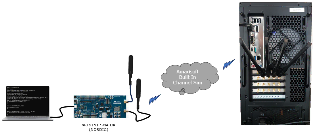
This test is with a commercial UE from NORDIC nRF9151 SMA DK
Device Info
The information of the specific device and firmware information that was used in this test is as follows :
|
NORDIC nRF9151 SMA DK
Firmware version: mfw_nrf9151-ntn_1.0.0 |
Test Setup
Following shows the test setup for this test.
Configuration
The configuration shown here is common configuration for all the subtests belonging to Test 1 and I will not show this configuration repeatedly for every subtest.
I have used enb-nbiot-ntn-leo.cfg

I am using mme-ims.cfg and ue_db-ims.cfg as they are.
enb-nbiot-ntn-leo.cfg is configured as follows.
This configuration sets the NB-IoT NTN test mode for the Callbox and enables the internal satellite link emulator. NTN_MODE is used as the top-level switch to choose the orbit profile (GEO/MEO/LEO), and in this file it is set to LEO (NTN_MODE = 2). CHANNEL_SIM is enabled so the eNB uses its built-in downlink channel simulator to emulate the satellite path rather than relying on a real over-the-air link. Based on the selected orbit mode, MAX_HARQ is then defined to tune retransmission behavior for the expected propagation delay; in the LEO case it is set to a larger value (MAX_HARQ = 5), while GEO use a smaller value (MAX_HARQ = 2).

This configuration enables the satellite-link emulation and sets two practical parameters for making the NTN-style link stable. When CHANNEL_SIM is enabled, the rf_ports section attaches a downlink channel model, and here it is configured as a simple AWGN channel with noise_level: -50, which provides a clean baseline impairment model for early tests. In addition, rx_ta_offset is set to add an uplink timing offset (in 1/1.92 �s units) used by the receiver; with a well-calibrated radio head it helps the PRACH-derived timing advance for a nearby UE come out correctly, and using a small non-zero value is generally recommended to keep uplink timing alignment robust.
This nb_cell_default section defines the baseline NB-IoT cell behavior, especially how system information is broadcast and how a UE evaluates whether it can camp on the cell. It sets SI control values such as the global si_value_tag and the number of SIB1 repetitions (r_sib1), and it configures basic access/reselection conditions like cell_barred, intra_freq_reselection, and the minimum signal thresholds (q_rx_lev_min, q_qual_min) that are reflected in SIB1. It also defines the SI scheduling framework with si_window_length, si_radio_frame_offset, and enables per-SIB value tagging (si_value_tag_list_enable) so individual SIB updates can be tracked. Finally, sib_sched_list schedules NB-IoT system information (here sib2_nb.asn) with its periodicity and repetition pattern, which controls how often the UE can acquire the necessary SI for access and operation.
The following configuration shows the two key additions that make an NB-IoT cell behave as an NTN-capable cell. First, the sib31 block is explicitly configured so SIB31 is scheduled and transmitted, which is the Rel-17 NB system information used to carry NTN-related assistance information to the UE. Next, the ntn block defines the NTN operating context for the cell: it selects the orbit profile through default_ephemeris (geo/meo/leo) and sets ul_sync_validity to an orbit-appropriate value so the uplink synchronization assumptions remain stable under the expected satellite delay conditions. The same block also includes the ground station geometry via ground_position (latitude/longitude/altitude), which anchors the NTN calculations to the eNB location, and it can optionally enable state-vector style orbital data (use_state_vectors) when relevant. Overall, this section is where the configuration moves from "normal NB-IoT broadcast and access" to "NB-IoT NTN broadcast + orbit/geometry-aware behavior."

Following is the list of commands that are used at this step
|
/* SIB31 scheduling (Rel-17 NB-IoT NTN SI) */ sib31: { si_periodicity: 128, si_repetition_pattern: 4, si_value_tag: 0 },
/* NTN configuration (GEO example) */ ntn: { ul_sync_validity: 240, default_ephemeris: "geo", use_state_vectors: true,
ground_position: { latitude: 48.853, longitude: 2.348, altitude: 140 } }, |
This configuration shows two NTN-related configuration areas that are applied when the channel simulator is used. The first part, channel_sim_control, enables the feeder/service-link emulation mode and sets the UE's geographic position (ue_position) so the simulator can model service-link delay consistently with the assumed UE location. With ue_doppler_shift: true, the emulator also applies Doppler effects instead of keeping the carrier frequency perfectly static. The second part, mac_config, adjusts MAC reliability and timing behavior for the long-delay NTN environment by controlling how many HARQ attempts are allowed on UL/DL, how many consecutive retransmissions are tolerated before disconnect, and how often scheduling-related reports such as BSR are retried (periodic_bsr_timer, retx_bsr_timer). Together, these settings make the link emulation more realistic (geometry + Doppler) while keeping the MAC layer stable under the larger RTT and timing uncertainty of an NTN path.

Following is the list of commands that are used at this step
|
/* CHANNEL_SIM enabled: UE position + Doppler in feeder/service-link emulation */ channel_sim_control: { type: "auto_feeder_service_link", ue_position: { latitude: 43.295, longitude: 5.373, altitude: 20 }, ue_doppler_shift: true },
/* MAC tuning example (NTN) */ mac_config: { msg3_max_harq_tx: 1, ul_max_harq_tx: MAX_HARQ, dl_max_harq_tx: MAX_HARQ, ul_max_consecutive_retx: MAX_HARQ * 3, dl_max_consecutive_retx: MAX_HARQ * 3, time_alignment_timer_dedicated: 0, periodic_bsr_timer: 16, retx_bsr_timer: 512 }, |
This nb_cell_list entry defines the actual NB-IoT cell instance that the Callbox will transmit, meaning it sets the concrete broadcast identity and RF parameters that the DUT will camp on. It declares the served PLMN (plmn: "00101"), assigns a local cell_id (0x01), and sets the tracking area code (tac: 0x0002) that will appear in SIB1. It then selects the downlink frequency through dl_earfcn: 229300 (noted as band 256 in this setup) and fixes the antenna configuration to single-antenna downlink and uplink (n_antenna_dl: 1, n_antenna_ul: 1). The cell is configured in operation_mode: "standalone", so it operates as a standalone NB-IoT carrier rather than being in-band or guard-band with an LTE anchor. Finally, n_id_ncell: 37 provides the NB-IoT physical cell identity used for synchronization and broadcast identity on the air interface.
Perform the Test
This is not the mandatory process.. but I did this to collect SIB message in the log for a few seconds at the beginning. I did bcch=1 and after a few seconds did bcch=0.
![]()
Now start trace logging.
![]()
Configure on DUT side
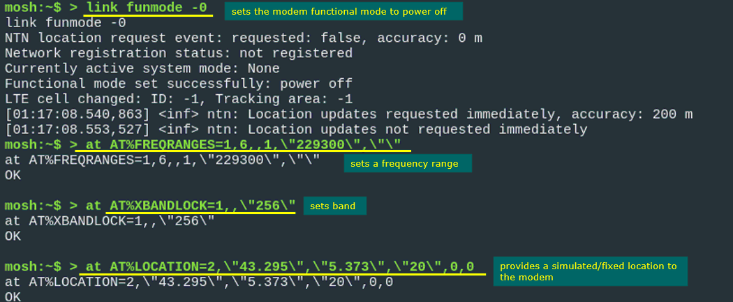
Following command set shows the modem preparation step before starting the NTN test. First, link funmode -0 sets the modem functional mode to power off, so the modem becomes not registered and the active system mode becomes None. Then AT%FREQRANGES is used to set the target frequency range, and the value 229300 is configured as the frequency-related setting for the modem search. Next, AT%XBANDLOCK is used to lock the modem to band 256, so the UE searches only the intended band instead of scanning other supported bands. Finally, AT%LOCATION is used to provide a fixed UE location. In this example, the latitude is set to 43.295, the longitude is set to 5.373, and the height is set to 20. This fixed location is useful for NTN testing because UE position can affect satellite-related timing and delay compensation. Overall, these commands make the test more controlled and repeatable by fixing the modem state, search frequency, operating band, and UE location before the modem is powered on again.
|
link funmode -0 ... mosh:~$ > at AT%FREQRANGES=1,6,,1,\"229300\",\"\" at AT%FREQRANGES=1,6,,1,\"229300\",\"\" OK
mosh:~$ > at AT%XBANDLOCK=1,,\"256\" at AT%XBANDLOCK=1,,\"256\" OK
mosh:~$ > at AT%LOCATION=2,\"43.295\",\"5.373\",\"20\",0,0 at AT%LOCATION=2,\"43.295\",\"5.373\",\"20\",0,0 OK |
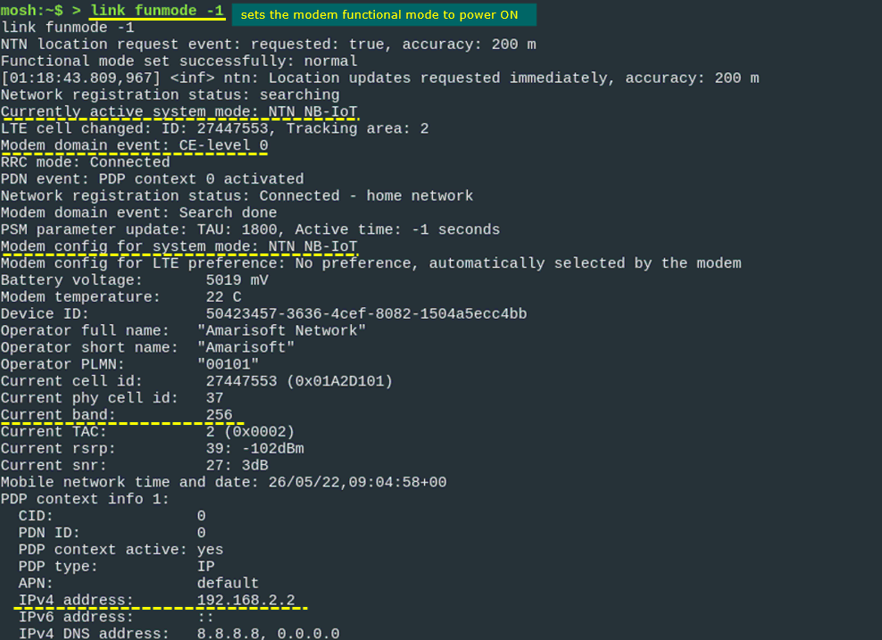
Following is the command for UE power on and status prints when UE attach is complete.
The command link funmode -1 sets the modem functional mode to power ON, and the modem changes to normal mode. After that, the UE starts network search and camps on the NTN NB-IoT system. The log shows Currently active system mode: NTN NB-IoT, which means the UE has selected the NTN NB-IoT radio access mode. The LTE cell is changed to cell ID 27447553 with tracking area 2, and the RRC mode becomes Connected. The network registration status becomes Connected - home network, which confirms that the UE has attached successfully. The modem configuration also shows system mode: NTN NB-IoT. The serving cell information shows operator name Amarisoft Network, PLMN 00101, current cell ID 27447553, physical cell ID 37, current band 256, and TAC 2. The radio condition is also printed with RSRP 39, shown as -102 dBm, and SNR 27, shown as 3 dB. Finally, the PDP context is active, with CID 0, PDN ID 0, PDP type IP, APN default, and IPv4 address 192.168.2.2. This means the UE is not only registered to the NTN NB-IoT network, but also has an active IP data context.
Wait until the DUT complete the initial attach.
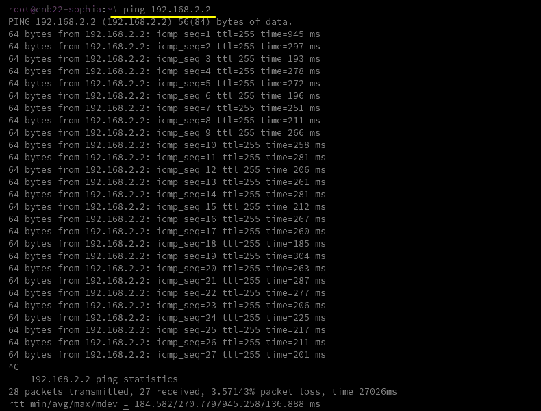
Following shows the data connection test after the UE attach is completed. The network side sends ping packets to the UE IPv4 address 192.168.2.2, which was assigned in the PDP context. Most packets receive replies, so the IP path between the network and UE is working. The ping result shows 28 packets transmitted and 27 packets received, which means only 1 packet was lost, corresponding to 3.57% packet loss. The round trip time is relatively large, with minimum 184.582 ms, average 270.779 ms, maximum 945.258 ms, and deviation 136.888 ms. This confirms that the UE has an active user-plane connection, but the latency is much higher and more variable than a normal terrestrial LTE/NB-IoT test, which is expected in an NTN scenario due to satellite-related propagation delay and timing compensation behavior.
Log Analysis
Following is the log snapshot that are involved in communication with NTN.
This is SIB1 on BCCH-NB, and the right-hand decode confirms that the NB-IoT cell is broadcasting the Rel-17 NTN indicators needed for the test. In the SIB1 extensions, sib-MappingInfo-v1530 points to sibType31-NB-r17, which tells the UE that the Rel-17 NB system information (SIB31 for NTN) is scheduled and can be acquired. It also shows cellAccessRelatedInfo-NTN-r17 with cellBarred-NTN-r17 = notBarred, meaning NTN access is allowed on this cell.

This is the NB-IoT Rel-17 NTN system information (SIB31-v1700) being transmitted on BCCH-NB. The important part is servingSatelliteInfo-r17, where the satellite ephemeris is provided in state-vector form through ephemerisInfo-r17 stateVectors (the positionX/Y/Z-r17 and velocityX/Y/Z-r17 fields). Below that, ntn-CommonParameters-r17 carries the common timing assistance values that the UE needs, including ta-Common-r17, ul-SyncValidityDuration-r17, and k-Offset-r17. This confirms that SIB31 is present and that both the satellite state vectors and the key NTN timing parameters are being broadcast as intended.

The underlined message is RRC connection request on CCCH-NB. In NB-IoT, the UE can only send this message after it has successfully finished the random access procedure (NPRACH detection → RAR received → UL resources granted). So seeing RRC connection request means the UE already got the uplink grant from the RAR and moved past the pure PHY/MAC access phase into the RRC connection establishment phase. On the details view, the message is shown as rrcConnectionRequest-r13 and includes the UE identity and establishment cause, which further confirms it is the first uplink RRC message that follows a successful RACH.

Thisy is the RRC Connection Setup message, and the right-side decode shows the dedicated SRB configuration that the eNB is sending to the UE. Inside `radioResourceConfigDedicated-r13`, the eNB provides the RLC and MAC main configuration values such as `t-PollRetransmit-r13` in the RLC AM configuration, along with MAC parameters like `periodicBSR-Timer-r13`, `retxBSR-Timer-r13`, and `timeAlignmentTimerDedicated-r13`. Since these fields are populated from the `mac_config` and related SRB/RLC settings in your configuration file, this screen confirms that the MAC/RLC behavior you tuned is not only set locally but is actually being delivered to the UE over the air as part of the connection setup.

This is RRC "UE capability enquiry" on DCCH-NB, which is sent by the eNB after the connection is established to request the UE to report its supported feature set. In the right-side decode you can see it as ueCapabilityEnquiry-r13, which is the trigger for the UE to respond with UE Capability Information. In this NTN test flow, this step is important because the following capability report is where you confirm that the UE advertises Rel-17 NTN support (for example, the presence of ntn-Parameters-r17), so this enquiry message marks the start of that capability validation phase

This RRC "UE capability information" on DCCH-NB, and the detailed view is showing the UE's supported band list. In rf-Parameters-r13, the UE reports supportedBandListEUTRA-r13, and in this capture it includes band 256. This is the UE telling the network which E-UTRA/NB-IoT operating bands it can support, and seeing band 256 here is particularly relevant for your NTN-oriented NB-IoT setup where those NTN bands are being used in the test

This is RRC UE Capability Information on DCCH-NB, and the details view confirms the NTN capability that the UE is advertising. In the phyLayerParameters-v1700 extension, the UE includes ntn-Parameters-r17, where ntn-Connectivity-EPC-r17 is marked supported, meaning the UE can operate in an NTN scenario while using EPC-based connectivity. The same block also shows ntn-ScenarioSupport-r17 = gso, indicating the UE reports support for a geostationary-style NTN scenario, which matches the GEO test mode you configured on the network side.

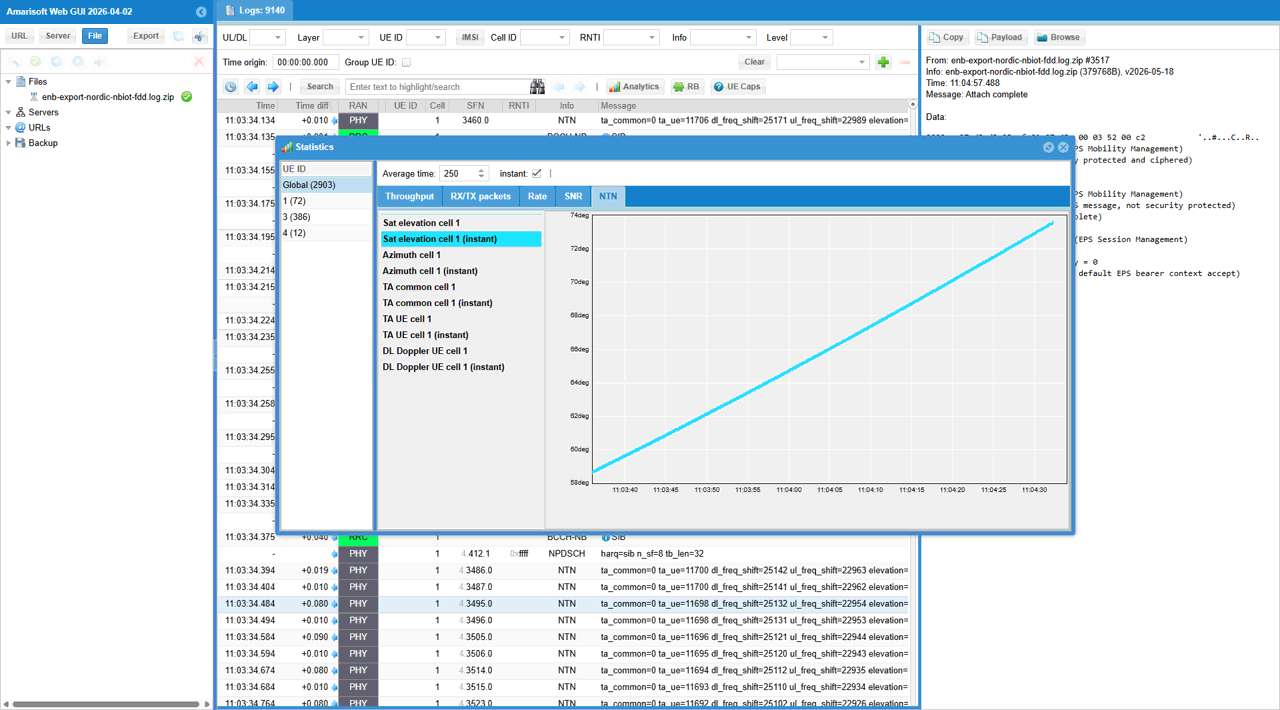
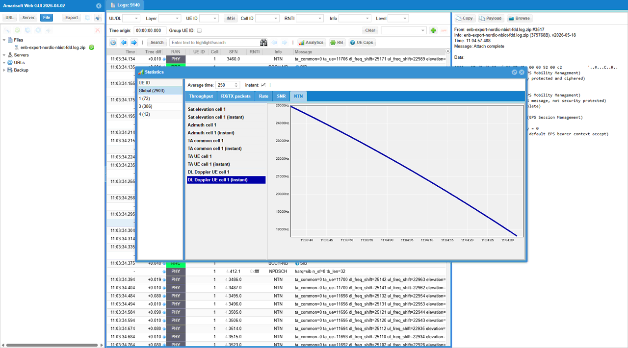
This screenshot shows the NTN monitoring view in Amarisoft Web GUI after the UE attach is complete. The log file is enb-export-nordic-nbiot-fdd.log.zip, and the selected UE is UE ID 1. In the message window, the attach procedure is already completed, and the right-side decode view shows Attach complete and EPS bearer context accept, meaning the UE has successfully registered and activated the default bearer. The Statistics window is opened with the NTN tab selected. The selected metric is Sat elevation cell 1 (instant), and the graph shows the satellite elevation increasing over time from around 58 degrees to around 74 degrees. This indicates that the simulated or configured satellite position is changing during the test, and the UE/network NTN parameters are being updated accordingly. In the background PHY log, NTN-related values such as TA common, TA UE, DL frequency shift, UL frequency shift, and elevation are repeatedly printed, showing that the eNB is continuously tracking or applying NTN timing and frequency compensation values during the NB-IoT NTN connection.
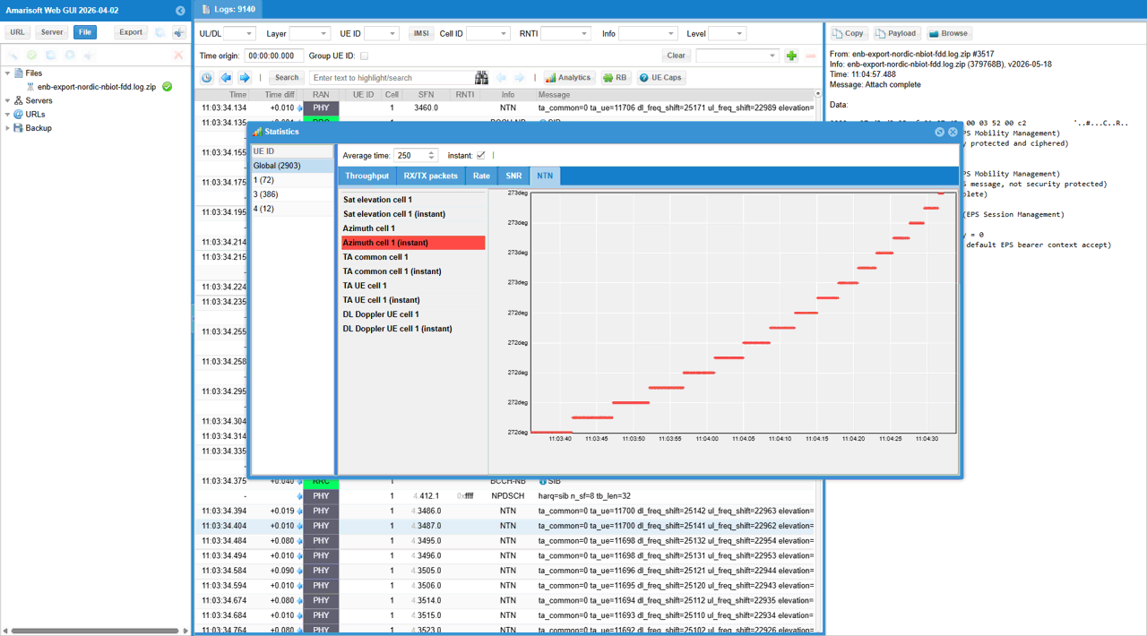
This screenshot shows another NTN statistic after the UE attach is complete. The Statistics window is opened with the NTN tab selected, and the selected metric is Azimuth cell 1 (instant). The graph shows the satellite azimuth changing relatively small degree in range during the observation period. This means the simulated satellite direction is not fixed. It is being updated over time as the NTN scenario progresses. In the background log, the UE is already attached, and NTN-related PHY parameters such as TA common, TA UE, DL frequency shift, UL frequency shift, and elevation are continuously printed. This confirms that the system is not only maintaining the NB-IoT NTN connection, but also tracking the changing satellite geometry and applying the corresponding timing and frequency compensation values.
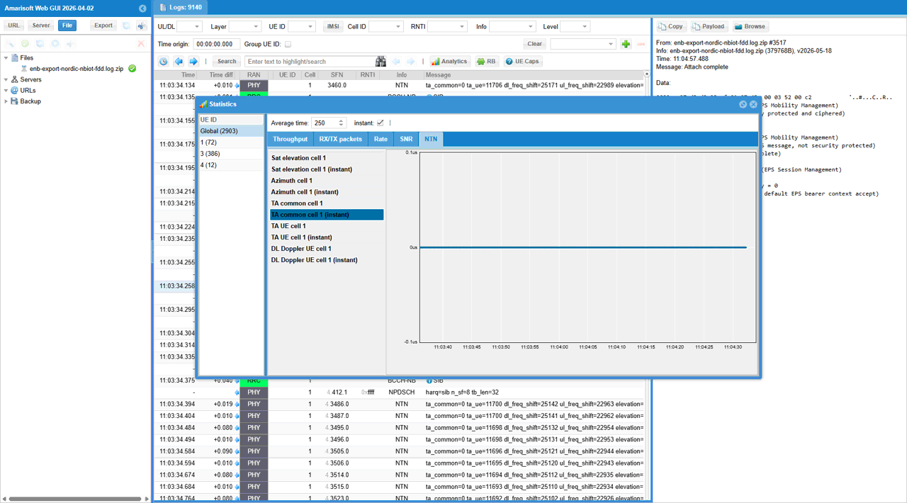
This screenshot shows the NTN statistics view for TA common cell 1 (instant). The UE attach is already completed in the background, and the NTN tab is used to monitor satellite-related parameters. In this graph, TA common stays flat at 0 us during the whole observation period. This does not mean that common TA is not supported or not applied. It means that the common TA value remains unchanged in this test condition. This is normally expected because common TA is a cell-level timing component and usually does not need to change frequently. In contrast, UE-specific or satellite-geometry-related values may change more often as the UE position, satellite position, Doppler, or timing relation changes.
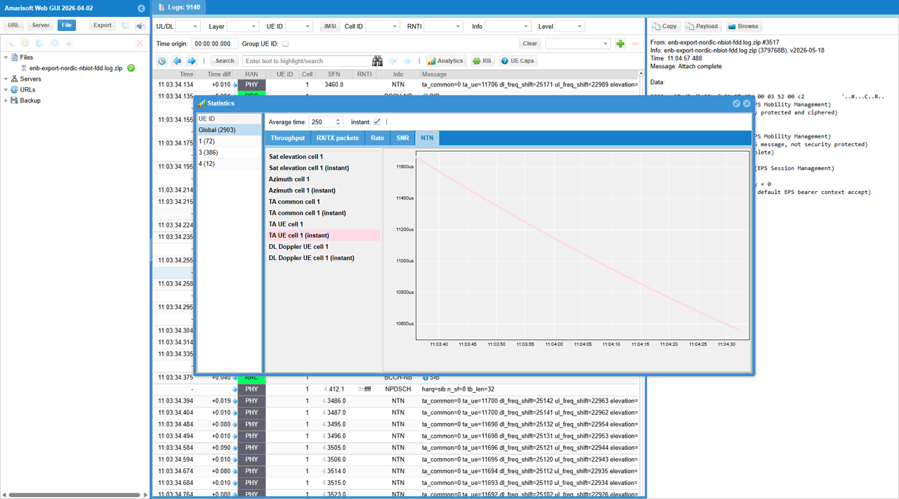
This screenshot shows the NTN statistics view for TA UE cell 1 (instant). The UE attach is already completed in the background, and the selected NTN metric is the UE-specific timing advance. In this graph, TA UE gradually decreases from about 11700 us to about 10600 us during the observation period. This means the UE-specific timing compensation is being updated as the NTN geometry changes. Unlike TA common, which usually stays stable because it is a cell-level timing component, TA UE can change more dynamically because it reflects the timing relation for this specific UE. In this test, the decreasing TA UE value indicates that the effective propagation delay between the UE and the satellite/network timing reference is becoming smaller over time.
This screenshot shows the NTN statistics view for DL Doppler UE cell 1 (instant). The UE attach is already completed in the background, and the selected NTN metric is the UE-specific downlink Doppler compensation. In this graph, DL Doppler UE decreases from around 25000 Hz to around 18000 Hz during the observation period. This means the relative motion between the satellite and the UE is changing, so the downlink frequency offset that needs to be compensated is also changing. This behavior is expected in an NTN scenario because Doppler shift depends on satellite movement and UE-satellite geometry.
RRC / NAS Signaling
SIB31 (LTE)
: This is SIB31 containing ephemeris
{
message c1: systemInformation-r13: {
criticalExtensions systemInformation-r13: {
sib-TypeAndInfo-r13 {
sib31-v1700: {
servingSatelliteInfo-r17 {
ephemerisInfo-r17 orbitalParameters: {
semiMajorAxis-r17 8394210402,
eccentricity-r17 0,
periapsis-r17 0,
longitude-r17 242097885,
inclination-r17 0,
anomaly-r17 177192
},
nta-CommonParameters-17 {
nta-Common-r17 7776350
},
ul-SyncValidityDuration-r17 s240,
k-Offset-r17 1023
}
}
}
}
}
}
FAQ
I am putting a list of frequently asked questions and answers that would help everybody.
[Q1] why we need channel simulator ?
[A1] It is necessary to simulate the constantly changing real time position of the satellite
[Q2] do we always need to use the channel simulator ?
[A2] Yes for MEO or LEO in which delay and doppler varies relatively in large scale. Maybe optional to GEO in which delay and doppler does not vary widely. (NOTE : You may use the internal channel simulator at the testing phase in quick and easy way, but you can also use an external satellite channel simulator as well).
[Q3] What is the maximum delay simulated by Amarisoft Channel Simulator ?
[A3] Up to several seconds. The maximum value will depend on the sample rate, the value is max_delay in s = 2.147e9 / (sample_rate in Hz). In NB-IoT, for example, the sample rate is usually 1.92 MHz, so the max_delay is around 1118 seconds.
[Q4] What is the minimum configurable altitude of a satellite ?
[A4] The 3GPP encoding for the semi-major axis has a minimum of 6500 km, so a minimum of 122(=6500-6378) km altitude, where 6378 is the radius of the earth
[Q5] For ue_position, ground_position, we allow the altitude with the range of -1000m to 20km, what is the reason to allow negative values ?
[A5] It is to configure altitude below sea level. (https://en.wikipedia.org/wiki/List_of_places_on_land_with_elevations_below_sea_level )