NR SA NTN (Non Terrestrial Network)
This tutorial is to show you how to configure and test NR NTN. NTN (Non Terrestrial Network) is a type of network deployment in which some type of non-terrestrial (e.g, satellite or other airborne component). Overall protocol sequence of NTN is not much different from the existing NR RAN access (LTE NB, LTE, NR), but one major difference is to handle the long propagation delay between the ground components (eNB and/or DUT) and Satellite. There are one major components introduced in 3GPP NR NTN as listed below.
- Additional SIBs : This is mainly to inform the position of Satellite (i.e, ephemeris) and default time delay. In LTE case, the SIB19 carries these information.
There are various different type of NTN deployment in 3GPP TR 38.821. Currently Amarisoft NTN implementation is as shown below.

Table of Contents
- NR SA NTN (Non Terrestrial Network)
- Introduction
- Summary of the Tutorial
- Test Setup
- Key Configuration Parameters
- Before You Start : Time Synchronization
- Test 1 : NTN with Simulated GEO and UEsim
- Test 2 : NTN with LEO
- With generated satellite and embedded simulator
- With a 3rd party external simulator or a real satellite
- SubTest 1 : LEO NTN with Amarisoft gNB and Amarisoft UEsim
- Test 3 : NTN to TN Handover
- Test 4 : Conditional Handover
- RRC / NAS Signaling
- FAQ
Introduction
The emergence of Non-Terrestrial Networks (NTN) within the 3GPP New Radio (NR) framework represents a significant advancement in wireless communication, enabling seamless connectivity in environments traditionally underserved by terrestrial infrastructure. NTN leverages non-terrestrial platforms such as satellites or airborne vehicles to extend the reach of 5G NR services to remote, rural, oceanic, and disaster-struck areas where ground-based networks may be impractical or economically unfeasible. Architecturally, NR NTN is designed to integrate with the existing NR Radio Access Network (RAN), preserving core protocol sequences while addressing unique challenges posed by the satellite or aerial link—most notably, the considerable propagation delays between terrestrial entities (e.g., gNB or Device Under Test) and their non-terrestrial counterparts. To accommodate these challenges, 3GPP has introduced enhancements such as additional System Information Blocks (SIBs), specifically tailored to deliver satellite-specific parameters like ephemeris data and default time delay, ensuring robust network synchronization and performance. The implementation of NR NTN, as detailed in 3GPP TR 38.821 and realized in platforms such as Amarisoft, empowers network operators and researchers to evaluate end-to-end NTN scenarios, test protocol adaptations, and validate service reliability under the unique conditions of non-terrestrial environments. This tutorial provides a practical guide to configuring and testing NR NTN deployments, equipping learners with the foundational knowledge and procedural steps necessary to navigate this innovative domain of modern wireless systems.
-
Context of NR NTN Technology
- NR NTN extends 5G NR connectivity via non-terrestrial nodes (satellites, airborne platforms).
- Integrates with existing NR RAN architecture, sharing many protocol workflows with terrestrial NR/LTE systems.
- Addresses unique challenges such as high propagation delay and satellite-specific signaling requirements.
-
Relevance and Importance of the Tutorial Topic
- Enables connectivity for geographically isolated or infrastructure-deficient regions.
- Supports critical communications for maritime, aeronautical, and emergency response scenarios.
- Facilitates testing and validation of protocol adaptations required for NTN environments.
- Aligns with current industry and research trends towards universal, resilient 5G coverage.
-
Learning Outcomes
- Understand NR NTN architecture and key protocol enhancements introduced by 3GPP.
- Gain hands-on experience with the configuration and operation of NR NTN testbeds (e.g., Amarisoft implementation).
- Develop the ability to analyze and troubleshoot NTN-specific issues such as timing, synchronization, and signaling.
- Acquire insights into deployment options and system information management for NR NTN scenarios.
-
Prerequisite Knowledge and Skills
- Familiarity with 3GPP NR (5G) and LTE system concepts and protocol layers.
- Basic understanding of wireless network architecture and radio access procedures.
- Experience with network configuration, protocol analysis, and diagnostic tools.
- Awareness of Amarisoft or similar 5G NR test platforms is beneficial but not strictly required.
Summary of the Tutorial
This tutorial describes procedures for low layer testing of NTN (Non-Terrestrial Networks) using Amarisoft eNB and UEsim. It covers two main tests: one with a simulated GEO satellite and another with LEO, focusing on configuration, execution, and troubleshooting steps.
-
Test Setup Overview
- Utilizes Amarisoft eNB (Callbox) and UEsim for low layer tests.
- SIM card is used as delivered; configuration changes can be referenced from the Configuration Guide.
- Two setups are possible depending on test objectives.
-
Key Configuration Parameters
- Extensive configuration parameters are available for NTN, including satellite orbit settings, channel simulation, timing/frequency adjustments, and position parameters for satellite, ground station, and UE.
- Important parameters: ntn, sv_filename, default_ephemeris, ephemeris group, ground_position, ue_position, channel_sim_control, large_freq_shift, and others related to timing advance and Doppler compensation.
-
Test 1: NTN with Simulated GEO and UEsim
-
Configuration Steps
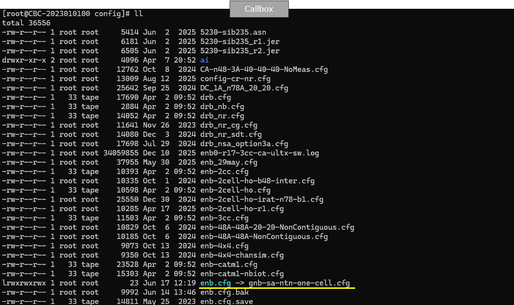
- Use gnb-sa-ntn.cfg on the Callbox/gNB as the base configuration.
- Select NTN_MODE as GEO. Configure parameters such as CSI_SRS_PERIOD, MAX_HARQ, T3XX_TIMER, SRB_T_POLL_RETX according to the selected mode.
- Enable CHANNEL_SIM (set to 'awgn' for this test) to simulate the radio link.
- Adjust ssb_period based on orbit type (set to 20 for GEO).
- Enable sib19 for broadcasting NTN-related information.
- Configure MAC timers (retx_bsr_timer, sr_prohibit_timer, prohibit_phr_timer, sr_trans_max) and RRC timers (t300, t301, t319, t_PollRetransmit) according to orbit RTT.
- Set ntn parameter to define positions for satellite (default_ephemeris), ground station (ground_position), and UE (ue_position).
- On UEsim, enable NTN functionality (ntn:true), and configure ntn_ground_position to match gNB's ue_position. Set as_release to 17 and specify the APN name as configured on the MME.
-
Test Procedure
- Start LTE service on the Callbox; verify cell configuration using 'cell phy' and 'cell' commands.
- (Optional) Enable BCCH to collect SIB logs initially; disable after a few seconds.
- Start trace logging.
- Power on the UE on UEsim (or turn on a commercial UE if used).
- Wait for the DUT to complete initial attach.
-
Log Analysis
- Verify in SIB1 that timers (t300, t301, t319) and NTN support indicator (cellBarredNTN) are as configured.
- Confirm SIB19 is transmitted and ntn-Config information is present (check ta-Common and ephemerisInfo).
- Check UE capability information for ntn-Parameters to confirm NTN support.
- At the lower layer, verify RACH process completion and that timing advance is periodically readjusted by the gNB.
-
Configuration Steps
-
Test 2: NTN with LEO
-
Simulation with Embedded Channel Simulator
- Use gnb-sa-ntn.cfg with NTN_MODE set to 2 for LEO mode.
- At startup, eNB generates a fast-moving satellite over its position; test window is approximately 5 minutes.
- default_elevation_offset can be tuned to control satellite pass duration and entry/exit points.
- On the UE, ensure the clock is tightly synchronized with the eNB. UE position must exactly match ue_position in gNB's NTN channel simulator configuration.
-
Testing with External Simulator or Real Satellite
- Synchronize clocks across all three devices: gNB, channel simulator, and UE. Use NTP for alignment, ideally with the channel simulator as NTP server.
- Use actual satellite ephemeris (TLE file) for realistic passes, but ensure the ability to replay passes by adjusting the time on all components.
- Mitigate timing and frequency offsets caused by model differences, hardware errors, or frequency translation units by:
- Using PRACH format 1 (configuration index 28-52) for increased cyclic prefix and timing tolerance.
- Setting rx_ta_offset to the middle of the PRACH window.
- Configuring large_freq_shift within the ntn object to enable frequency error estimation and correction based on PRACH signals (parameters include prach_range_sc, prach_n_acc, ta_tolerance, average_mode).
-
Integration and Troubleshooting Methodology
- Fine-tune parameters such as rx_ta_offset, root_sequence_index, compute_freq_shift, prach_config_index, and large_freq_shift subparameters to handle timing/frequency errors and ensure successful RACH and attach procedures.
- Continuous monitoring and log analysis are critical, especially for initial RACH and timing advance operations, as these are the most likely failure points in real LEO or external simulation environments.
-
Simulation with Embedded Channel Simulator
The tutorial emphasizes careful configuration matching, clock synchronization, and robust parameter tuning as essential for successful NTN low layer testing, especially when simulating dynamic satellite environments or integrating with external simulation/hardware components.
Test Setup
Test setup for this tutorial is as shown below. This is just for low layer testing, you may not need any complicated IP layer setup.
- SIM Card used in this tutorial is the one delivered with the system as it is.
- If you want to change the configuration, The tutorial Configuration Guide would help
With Amarisoft eNB and UEsim, we can try with following two different setups. This figure presents two high-level test setups that can be built with Amarisoft eNB and UEsim for satellite-relay style scenarios, mainly to compare a more realistic over-the-air path with a fully simulated lab path. In setup [A], the satellite relay and space channel are treated as real, while the ground station uses an Amarisoft Callbox (eNB) and a real UE on the user side. In setup [B], the satellite relay and space channel are simulated, and both the ground station side and UE side are implemented in the lab using Amarisoft Callbox and Amarisoft UEsim. The key idea is that these two setups let you test similar end-to-end concepts at different levels of realism, cost, and controllability, from field-like validation to fully repeatable lab experimentation.

Key Configuration Parameters
Followings are important configuration parameters for this tutorial. You may click on the items for the descriptions from Amarisoft documents.
- ntn : In this link, you can find the descriptions for all the parameters below.
- ephemeris
- use_state_vectors
- eci_reference
- ground_position
- n_ta_common
- n_ta_drift
- n_ta_drift_var
- n_ta_common_offset
- feeder_doppler_compensation
- feeder_dl_freq
- feeder_ul_freq
- large_freq_shift
- direct_to_cell
- channel_sim_control
- type
- ue_position
- ue_doppler_shift
- ue_dl_freq
- ue_ul_freq
- feeder_doppler_shift
- ue_dl_attenuation
- ue_dl_gain_offset
- ul_sync_validity
- k_offset
- k_mac
- dynamic_k_offset
- reference_location
- t_service
- neighbour_cells
- rat_type
- t318
Before You Start : Time Synchronization
In NTN (Non-Terrestrial Networks), time synchronization across all communicating entities (satellite, gNB, UE, gateways, and sometimes multiple satellites) is fundamental, not just an implementation detail. This is because time directly maps to distance, frequency, and geometry in NTN.
There are multiple layers of technology required to achieve timing synchronization in NTN systems. These layers span from fine-grained timing, such as GNSS-disciplined clocks, PTP (IEEE 1588), and PHY-level frame alignment, to relatively coarse-grained synchronization, such as system clock alignment across hosts.
Each layer serves a different purpose. Fine-grained timing is mandatory for air-interface operation, including OFDM symbol alignment, timing advance, and Doppler compensation. Coarse-grained timing is mainly used to keep different system components operating on a consistent time reference.
In this section, I focus on one of the base minimum requirements: timing synchronization via NTP. NTP may not be sufficient for NTN PHY operation, but it is still an important prerequisite at the system level. This becomes especially important when testing NTN using Amarisoft Callbox and UE-sim. In such setups, the gNB, UE-sim, channel models, and supporting software often run on separate hosts or containers. If their system clocks are not aligned at least at the NTP level, issues such as inconsistent logs, invalid timing assumptions, and misleading test results can occur.
Enable NTP Client on Fedora Linux (Chrony)
This tutorial explains how to enable and verify NTP time synchronization (client mode) on a Fedora system using chrony, which is the default NTP implementation on Fedora. (
Prerequisites
- Fedora Linux
- User with sudo privileges
- Internet or access to an NTP server
Step 1: Install Chrony
Chrony is usually installed by default, but you can ensure it is present:
|
sudo dnf install -y chrony |
Step 2: Enable and Start the Chrony Service
Enable chrony to start at boot and start it immediately:
|
sudo systemctl enable --now chronyd |
Verify the service status:
|
systemctl status chronyd |
You should see the service running (active).
Step 3: Enable NTP via timedatectl
Fedora uses timedatectl to manage system time synchronization.
Enable NTP:
|
sudo timedatectl set-ntp true |
Verify:
|
timedatectl status |
Expected output fields:
|
System clock synchronized: yes NTP service: active |
Step 4 (Optional): Configure Custom NTP Servers
Edit the chrony configuration file:
|
sudo nano /etc/chrony.conf |
Add or modify NTP servers, for example:
|
server 0.pool.ntp.org iburst server 1.pool.ntp.org iburst server time.google.com iburst |
Save the file and restart chrony:
|
sudo systemctl restart chronyd |
Step 5: Verify Time Synchronization
Check synchronization status:
|
chronyc tracking |
View NTP sources:
|
chronyc sources -v |
A reachable source marked with ^* indicates active synchronization.
Step 6 (Optional): Force Immediate Time Sync
If the system clock is significantly incorrect:
|
sudo chronyc makestep |
Troubleshooting
Check chrony service:
|
systemctl status chronyd |
Check logs:
|
journalctl -u chronyd |
Firewall (normally not required for client mode):
|
sudo firewall-cmd --list-all |
Summary
|
sudo dnf install -y chrony sudo systemctl enable --now chronyd sudo timedatectl set-ntp true chronyc tracking |
Your Fedora system is now configured as an NTP client and will keep accurate time automatically.
Test 1 : NTN with Simulated GEO and UEsim
This is to configure and test NTN for Simulated GEO using Amarisoft UEsim as DUT.
Configuration
The configuration shown here is common configuration for all the subtests belonging to Test 1 and I will not show this configuration repeatedly for every subtest.
I have used gnb-sa-ntn.cfg which is included in the default installation package on Callbox (gNB)

I am using mme-ims.cfg and ue_db-ims.cfg as they are.

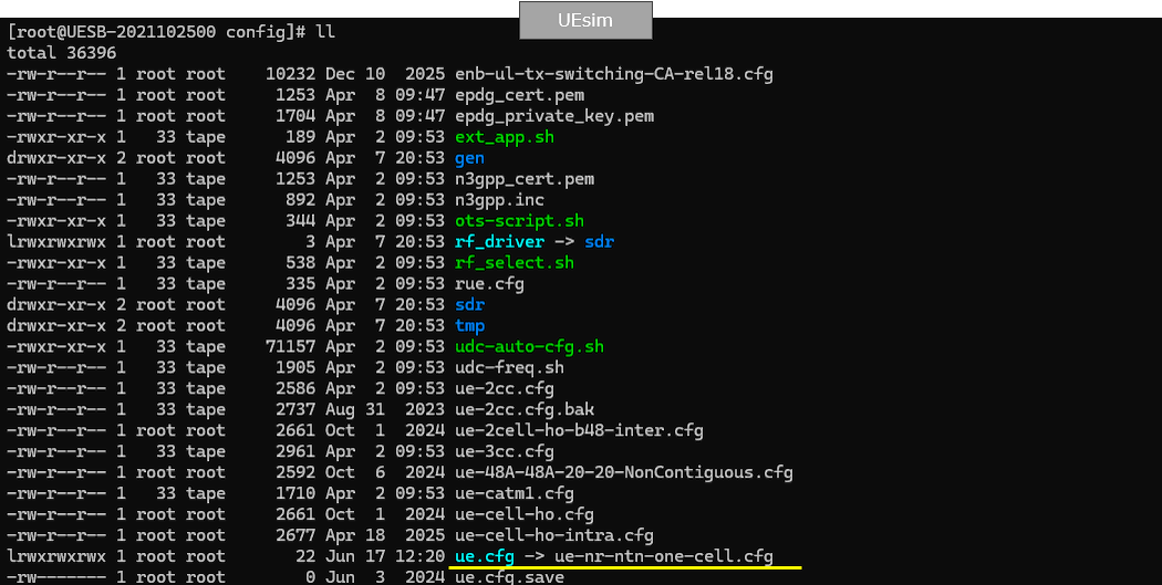
On UEsim, I used ue-nr-ntn.cfg which is included in the default installation package on UEsim (

gnb-sa-ntn.cfg is configured as follows.
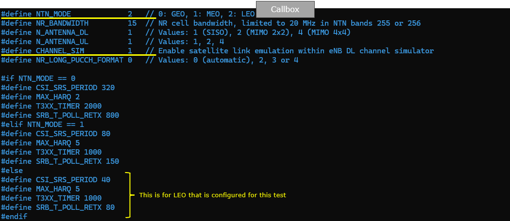
In gNB configruation,a single test parameter, NTN_MODE, is used as the top-level selector for satellite orbit type (GEO, MEO, or LEO), and the rest of the test behavior is adjusted from that choice. In the example, GEO is selected, and once that mode is fixed, several timing and retransmission-related parameters are set differently to match the expected propagation characteristics of the selected orbit, such as CSI_SRS_PERIOD, MAX_HARQ, T3XX_TIMER, and SRB_T_POLL_RETX. The figure also shows that CHANNEL_SIM is enabled so the eNB/gNB downlink channel simulator can emulate the satellite link between the ground station and the satellite relay. In other words, the configuration is organized so that one orbit-mode switch drives a consistent set of NTN-tuned radio and protocol parameters, making it easier to run comparable GEO/MEO/LEO tests without manually retuning every value each time.

Followings are the simplified configuration
|
#if NTN_MODE == 0 #define CSI_SRS_PERIOD 320 #define MAX_HARQ 2 #define T3XX_TIMER 2000 #define SRB_T_POLL_RETX 800 #elif NTN_MODE == 1 #define CSI_SRS_PERIOD 80 #define MAX_HARQ 5 #define T3XX_TIMER 1000 #define SRB_T_POLL_RETX 150 #else #define CSI_SRS_PERIOD 40 #define MAX_HARQ 5 #define T3XX_TIMER 1000 #define SRB_T_POLL_RETX 80 #endif |
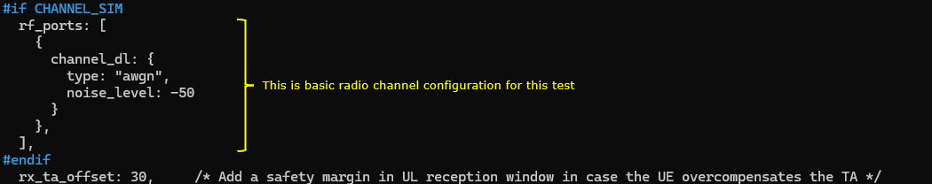
If CHANNEL_SIM is enabled, you can apply various channel profile to simulate the radio link between ground station and satellite. In this test, only awgn is applied. This setting allows the test setup to simulate the radio link between the ground station and the satellite within the lab. In this example, the downlink channel profile is configured under rf_ports using channel_dl, and the selected channel model is awgn, which applies additive white Gaussian noise to the signal path with a specified noise_level (shown as -50). The key idea is that once channel simulation is turned on, the test can replace the real space channel with a controlled and repeatable emulated channel condition, and in this particular case the scenario is simplified to AWGN-only behavior rather than using more complex fading or propagation models.

SSB periodicity is adjusted based on orbit type. In this test (with GEO), ssb_period is set to 20. This configuration shows an example of orbit-dependent NR cell parameter tuning in the gNB configuration, specifically for SSB periodicity. The nr_cell_list entry defines the NR cell basics (RF port, cell ID, band, ARFCN, subcarrier spacing, and SSB bitmap), and then uses a conditional block based on NTN_MODE to set ssb_period differently for different orbit types. In the example, when NTN_MODE == 0 (GEO), ssb_period is set to 20, while non-GEO modes use a shorter value (shown as 5) to place SSBs more closely for better UE-side timing estimation. The main idea is that even basic broadcast timing parameters like SSB periodicity may need to be tuned according to orbit characteristics, and the configuration is structured so this can be switched automatically by the same NTN mode selector used elsewhere.

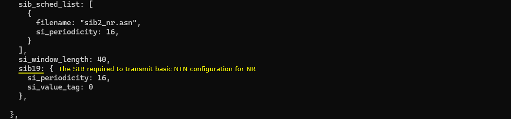
Then enable sib19 which is to broadcast NTN related information. This example shows the NR cell default configuration section where NTN-related broadcast information is enabled by scheduling SIB19, which is the NR system information block used for NTN-specific information. The example places this under nr_cell_default, alongside general NR defaults such as bandwidth and antenna settings, and then configures system-information scheduling through sib_sched_list, si_window_length, and a dedicated sib19 block. In the shown configuration, sib19 is explicitly enabled with its own si_periodicity and si_value_tag, which means the gNB will periodically broadcast the NTN-related system information needed by the UE. The key idea is that NTN support is not only about radio timing and channel emulation parameters, but also about enabling the correct NR broadcast signaling so the UE can receive NTN-specific system information during cell access and operation.

Followings are the simplified configuration
|
sib19: { si_periodicity: 16, si_value_tag: 0 }, |
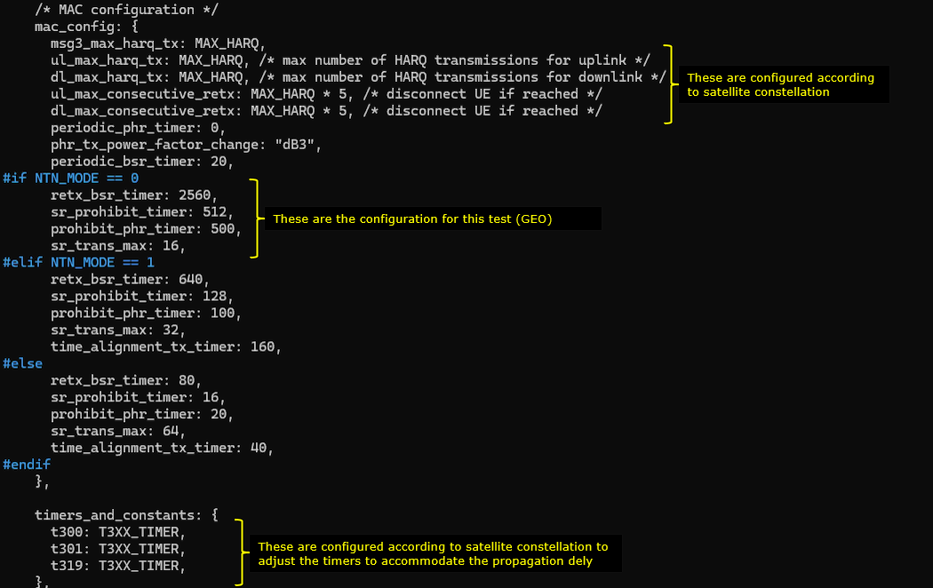
The basic idea is to configure these parameters differently based on RTT between the satellite and ground station. This settings shows the MAC-layer NTN tuning concept in the gNB configuration, where several MAC timers and limits are set differently depending on the selected orbit type (NTN_MODE) so they better match the expected round-trip time between the ground station and the satellite. The configuration uses conditional blocks (for GEO, MEO, and LEO) to assign different values to parameters such as retx_bsr_timer, sr_prohibit_timer, prohibit_phr_timer, and sr_trans_max, while also keeping the rest of the MAC configuration (such as HARQ-related limits and power-reporting behavior) in the same mac_config structure. The main idea is that these MAC behaviors should not use a one-size-fits-all setting in NTN, because GEO, MEO, and LEO have very different delay characteristics, and the timer values need to be scaled so retransmission, scheduling request, and power reporting procedures remain stable and efficient under each orbit�s RTT conditions.

Followings are the simplified configuration
|
mac_config: { msg3_max_harq_tx: MAX_HARQ, ul_max_harq_tx: MAX_HARQ, /* max number of HARQ transmissions for uplink */ dl_max_harq_tx: MAX_HARQ, /* max number of HARQ transmissions for downlink */ ul_max_consecutive_retx: MAX_HARQ * 5, /* disconnect UE if reached */ dl_max_consecutive_retx: MAX_HARQ * 5, /* disconnect UE if reached */ periodic_phr_timer: 0, phr_tx_power_factor_change: "dB3", periodic_bsr_timer: 20,
retx_bsr_timer: 2560, sr_prohibit_timer: 512, prohibit_phr_timer: 500, sr_trans_max: 16 }, |
Then adjust RRC timers t300, t301, t319 appropriately for each orbit type. And then adjust t_PollRetransmit based on the type of the orbit. This setting shows the RRC-layer and SRB-related timer tuning step in the NTN-oriented gNB configuration, where orbit-dependent values defined earlier (through macro-style parameters such as T3XX_TIMER and SRB_T_POLL_RETX) are applied to actual protocol settings. In the timers_and_constants block, the RRC timers t300, t301, and t319 are assigned from T3XX_TIMER, so the same orbit-based timing policy can be consistently reused across multiple RRC procedures. In the srb_config block, t_PollRetransmit for SRB entries is assigned from SRB_T_POLL_RETX, which adjusts SRB retransmission behavior according to the selected orbit type and its RTT characteristics. The key idea is to centralize NTN mode-dependent timing decisions in one define section and then propagate those values into RRC and SRB configuration blocks, making the configuration easier to maintain and less error-prone when switching between GEO, MEO, and LEO tests.

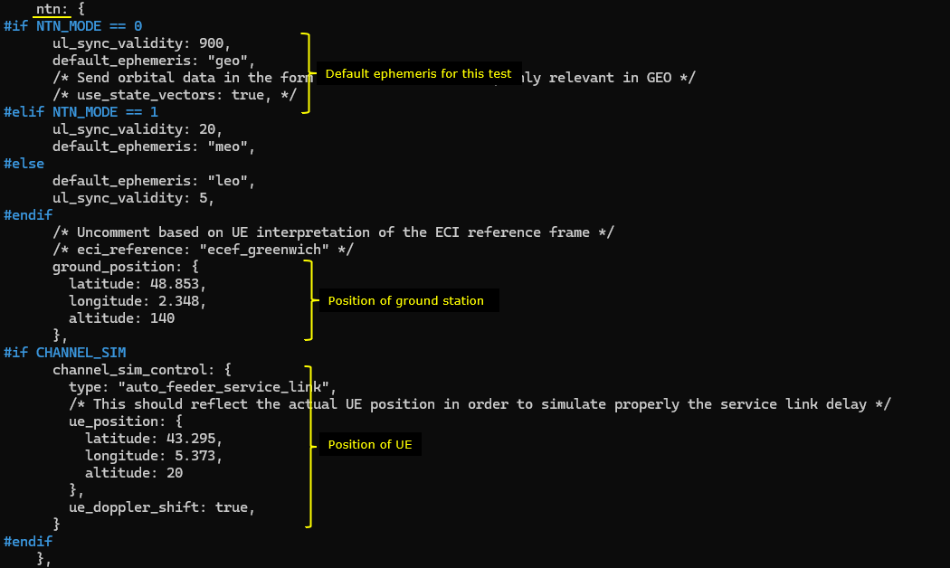
Now for the configurations specific for ntn. The configuration parameter name itself is ntn. This settings shows the NTN-specific configuration block in the gNB configuration, where the parameter subtree named ntn is used to define orbit-dependent satellite information and the geographic positions needed for NTN operation or emulation. Inside this block, the configuration selects orbit-specific ephemeris behavior (for example geo, meo, or leo) and related timing validity such as ul_sync_validity, typically driven by the same NTN_MODE conditional logic used elsewhere. It then defines the ground station position (ground_position) with latitude, longitude, and altitude, which represents the location of the gNB, and�when channel simulation is enabled�defines the UE position (ue_position) inside the channel simulation control section so service-link delay and Doppler effects can be modeled more realistically. The figure also highlights that in UEsim-based testing, the UE position used here should be consistent with the UE-side configuration, so both ends of the emulated NTN link use the same geographic assumptions. Overall, this block is the place where NTN configuration moves from generic timer tuning into geometry-aware satellite/ground/UE modeling.

Followings are the simplified configuration
|
ntn: { ul_sync_validity: 240, default_ephemeris: "geo",
ground_position: { latitude: 48.853, longitude: 2.348, altitude: 140 },
channel_sim_control: { type: "auto_feeder_service_link", ue_position: { latitude: 43.295, longitude: 5.373, altitude: 20 }, ue_doppler_shift: true }, }, |
ue-nr-ntn.cfg is configured as shown below. (
In UEsim configuration, you need to enable ntn functionality first by setting ntn:true and then configure the position of the UEsim. The position of UEsim is configured by the parameter ntn_ground_position and the ntn_ground_position on UEsim should match ue_position in gNB settings. This UE simulator configuration enables NTN mode for an NR test cell and sets the UE-side geographic position used for NTN-related delay/Doppler interpretation. At a high level, it defines one NR cell group for UEsim with the basic radio parameters (band, ARFCN, bandwidth, SCS, antenna settings), then explicitly turns on NTN behavior with ntn: true. The key NTN-specific part is ntn_ground_position, which represents the UE (DUT) location in the simulation, and this position should be aligned with the UE location configured on the gNB side (for example, in ntn.channel_sim_control.ue_position) so both ends use the same geometry when emulating the satellite service link.

Followings are the simplified configuration
|
cell_groups: [{ .. ntn: true,
ntn_ground_position: { latitude: 43.295, longitude: 5.373, altitude: 20 }, }], }], |
This part of the UEsim configuration defines the UE profile and capability settings used for the NTN test. It specifies the subscriber identity and key (imsi, K), then sets as_release: 17 so the simulated UE advertises Release 17 capability, which is required for NTN support. It also sets the UE category as NR and specifies the APN to be used for the data session (for example, ntn-internet). The important operational point is that the APN configured here must match an APN entry configured in the Callbox
core (mme.cfg / pdn_list) so PDN/PDU session establishment can succeed during the test.. (

Perform the Test
Run lte service on callbox and then check 'cell phy' and 'cell' command. Make it sure that cell is configured as you intended.
This step is a post-configuration verification on the Amarisoft Callbox to confirm that the NTN test cell is running with the intended radio parameters. After starting the LTE service, the cell phy and cell commands are used to inspect the active cell�s PHY-level and logical cell settings, such as NR band, bandwidth, ARFCN, antenna configuration, SCS, SSB ARFCN/SCS, PCI, TAC, and PLMN. In the example, the output confirms an NR cell on band n256, which is used here because it is a 3GPP NTN-related band, while the note also clarifies that the practical choice of band can depend on the equipment capabilities and test purpose. The main idea is to validate that the live runtime configuration matches the intended test configuration before proceeding with UE attach and NTN behavior testing..

This is not the mandatory process.. but I did this to collect SIB message in the log for a few seconds at the beginning. I did bcch=1 and after a few seconds did bcch=0.
![]()
Now start trace logging.
![]()
Power on UE on UEsim (If your DUT is a commercial phone, turn on the phone)

Wait until the DUT complete the initial attach. (

Log Analysis
Following is the log snapshot that are involved in communication with NTN.
First check SIB1 and see if the timers are configured as you intended and the cell is properly broadcasting about NTN supportability. The timers you need to check is t300,t301 and t319 in ue-TimersAndConstraints and the NTN supportability can be checked by the IE cellBarredNTN. Check the ue-TimersAndConstants fields (specifically t300, t301, and t319 ) to verify they match the orbit-tuned values you configured. At the same time, you confirm NTN support signaling by checking the cellBarredNTN information element, which indicates whether NTN access is barred or allowed for the cell. The key idea is to verify not just the config file values, but the actual broadcasted RRC content seen by the UE, ensuring the NTN-capable cell is advertising the intended behavior before attach and service testing.

Now check if SIB19 is transmitted and ntn-Config IE is populated as you intended. The important information in this SIB is ta-Common and ephemrisInfo. Check that SIB19 is present, then look inside ntn-Config for the key NTN fields -- especially ta-Common (within the TA-related common information) and ephemerisInfo -- because these carry the timing and orbit-related information the UE needs for NTN operation. The main idea is to verify that enabling sib19 in configuration resulted in the correct broadcast NTN assistance information, not just that the scheduler is configured to send it.

With powering on UE and UE is doing the initial attach, check UE capability information and make it sure that the UE support ntn. If the UE capability information message contains the IE ntn-Parameters, it mean the UE support NTN. Look for the presence of the ntn-Parameters information element. If ntn-Parameters appears in the decoded UE capability message, it indicates the UE is advertising NTN support (Release 17 NTN-related capability) to the network. The key idea is to verify the UE�s declared capability at signaling level before interpreting later attach, registration, or data-session behavior as NTN-related success or failure.

At the lower layer log, confirm that RACH process went through. (

After the connection is established, gNB would re adjust timing advance periodically to maintain the connection by sending Timing Advance MAC CE. After the UE connection is established, the gNB continues to maintain uplink timing alignment by periodically sending Timing Advance (TA) MAC Control Elements. In the MAC logs, these appear as TAG updates (for example, TAG:0 ta=...), and the repeated entries show that the network is actively refreshing the UE�s timing advance rather than leaving it fixed after random access. The spacing of these updates is tied to timing-related MAC behavior and practical link conditions, and in this example the periodicity is around the configured/default alignment-maintenance timescale (highlighted in the log view). The key point is that a successful NTN connection is not only about completing attach; it also requires ongoing timing maintenance, and periodic TA MAC CE transmission is a strong sign that the gNB is sustaining the link after access and setup.

Test 2 : NTN with LEO
This part is intended as a troubleshooting guide for all the issues you can encounter when testing LEO (Low Earth Orbit). Most of the difficulties come from the fact that a satellite in low earth orbit will move very quickly relative to the surface of the earth.
With generated satellite and embedded simulator
Performing a test with Amarisoft embedded channel simulator will remove most of the difficulties. You can use the standard configuration gnb-sa-ntn.cfg and set the macro NTN_MODE to 2.
At startup, the eNB will generate a satellite directly over the eNB position, and rapidly moving to the east from there on. You will have around 5 minutes during which the simulated satellite is visible to perform the test.
You can adjust the default_elevation_offset parameter to instantiate the satellite before or after its zenith pass if you want to experiment with a longer test duration or on the opposite to quickly simulate the behaviour when the satellite goes beyond visibility
On the UE side, the most important thing to check is that
Of course, as with GEO testing, the UE position also needs to match the position specified by the parameter ue_position of the gNB NTN channel simulator
With a 3rd party external simulator or a real satellite
Most issues will arise when testing with an external channel simulator, here are the most obvious ones, and how to mitigate them
Clock synchronization
With an external channel simulator, you have now three devices that need to be perfectly in sync: The gNB, the channel simulator and the UE.
You will also use ephemeris from a real satellite with a TLE file, instead of the 'default_ephemeris' so there will be only a few passes per day, on precise timing : This is not convenient for testing.
So, you need to have the ability to
One solution is to set one component of the system, eg the channel simulator, as an NTP server. And setup NTP client on eNB and UE side to fetch the date and time from the channel simulator.
Timing and frequency errors
Errors between the calculation performed on eNB side, UE side and channel simulator will in the end gives some errors on the eNB UL side: The timing and frequency of the UL signal received from the UE will be off.
The main causes for these errors will be :- Clock synchronization issues, see above
- Difference in satellite propagation model between eNB/UE and 3rd party channel simulator. To have better result, it is important to use a recent TLE file (less than a day), especially if the orbit altitude is low.
- There can be a lot of frequency translation units if the satellite links are over Ka/Ku band and each of these can add a frequency error. When using high frequency links, a small ppm error gives a rather larger frequency error in Hz
By carefully configuring the setup, these errors can be minimized but the eNB still needs to be robust to unforeseen errors.
Concerning the timing robustness, it is best to use PRACH format 1 (prach_configuration_index from 28 to 52), which has the biggest cyclic prefix. Since the timing inaccurracy can occur in both directions, it is advised to set rx_ta_offset in the middle of the PRACH reception window.
Concerning the UL frequency robustness, the problem is that NR (and OFDM protocol in general) are very sensitive to frequency error, and there is no builtin mechanism in the NR protocol to signal the UE of a frequency error.
So the eNB needs to rely on an ad-hoc solution to estimate the frequency error based on signal received from the UE and correct them. Note that this solution will only work if all the UE<->eNB links will share the same kind of frequency errors.
The large_freq_shift configuration object is used to estimate the frequency error seen on the PRACH signals. The gNB will perform some measurements on the first PRACH (and discard them) before applying a frequency correction and resuming normal PRACH operations.
Putting it all together
Here are the relevant parameters of the configuration file that need to be present and/or tuned depending on how the integration is going :
  rx_ta_offset: 650,                    // Middle of the timing reception window of the PRACH
  [...]
  nr_cell_list: [
  {
    [...]
    root_sequence_index: 12,            // This root sequence index give consistent results when signal frequency is off
    compute_freq_shift: true,           // Necessary for the large_freq_shift feature
    prach: {
      prach_config_index: 40,           // PRACH format 1, once every 2 frames
      zero_correlation_zone_config: 0,  // Maximum timing error tolerance
      ra_response_window: 10,
      ssb_per_prach_occasion: 1,
      cb_preambles_per_ssb: 8,
      [...]
    },
    [...]
    ntn: {
      large_freq_shift: {
        prach_range_sc: 128,            // Maximum frequency error correction in PRACH SCS unit. (Here 128*1.25KHz = 160 kHz)
        prach_n_acc: 5,                 // Number of PRACH to accumulate before estimating the frequency offset
        ta_tolerance: 8,                // TA range below which PRACH are considered coming from the same UE
        average_mode: true,             // Averaging strategy to determine the frequency error based on the prach_n_acc PRACHs : average or mode
      },
      [...]
    }
SubTest 1 : LEO NTN with Amarisoft gNB and Amarisoft UEsim
This subtest is to show how to configure Amarisoft gNB and Amarisoft UEsim to configure and test NTN for LEO constellation.
Configuration
For gNB, gnb-sa-ntn-once-cell.cfg will be used. It was copied and modified from gnb-sa-ntn.cfg
For UEsim, ue-nr-ntn-once-cell.cfg will be used. It was copied and modified from ue-nr-ntn.cfg
gnb-sa-ntn-once-cell.cfg is configured as follows.
In this Callbox configuration, NTN_MODE is set to 2, which selects LEO mode. NR_BANDWIDTH is set to 15, meaning the NR cell bandwidth is configured as 15 MHz, and both DL and UL antenna numbers are set to 1, so this test uses a SISO configuration. CHANNEL_SIM is enabled, so the downlink satellite channel is emulated inside the gNB DL channel simulator. NR_LONG_PUCCH_FORMAT is set to 0, which lets the system automatically select the long PUCCH format.
Since NTN_MODE is configured as LEO, the LEO-specific parameter set in the final conditional block is applied. CSI_SRS_PERIOD is set to 40, MAX_HARQ is set to 5, T3XX_TIMER is set to 1000, and SRB_T_POLL_RETX is set to 80. These values are shorter than the GEO and MEO cases because LEO has a much shorter propagation delay than GEO and MEO, so CSI/SRS reporting, HARQ operation, RRC timers, and SRB retransmission behavior can be configured with relatively smaller timing margins.
When CHANNEL_SIM is enabled, the rf_ports section defines the basic simulated radio channel used for this test. In this example, channel_dl is configured with type: "awgn", so the downlink channel is modeled as a simple additive white Gaussian noise channel without fading, delay spread, or Doppler-specific channel effects. noise_level: -50 sets the noise level used by the simulator, which controls the received signal quality in the emulated downlink path. This configuration is intentionally simple, so the test can focus on the NTN timing and LEO-related configuration behavior rather than complex radio propagation effects.
rx_ta_offset is set to 30 to add a safety margin to the uplink reception window. This helps the gNB tolerate cases where the UE slightly overcompensates the timing advance, which can be more important in NTN testing because the propagation delay and timing compensation are much larger than in normal terrestrial cells.
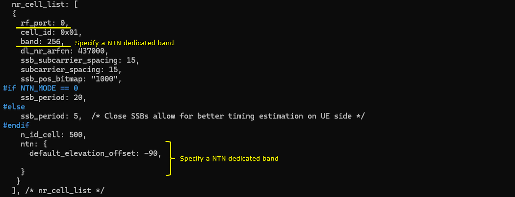
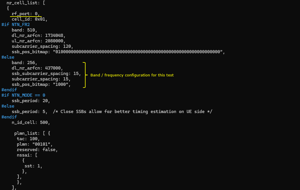
In the nr_cell_list configuration, rf_port: 0 maps this NR cell to the first RF port defined in the Callbox configuration. cell_id is set to 0x01, and band is set to 256, which is an NTN-dedicated NR band. dl_nr_arfcn is set to 437000, and the SSB is configured with 15 kHz subcarrier spacing, 15 kHz subcarrier spacing for the carrier, and ssb_pos_bitmap: "1000", meaning one SSB position is enabled.
Since NTN_MODE is enabled, ssb_period is set to 20. This gives the UE more time between SSB occasions, which is suitable for NTN operation where propagation delay and timing uncertainty are larger than in terrestrial cells. If NTN_MODE is not enabled, the configuration uses ssb_period: 5 instead, because closer SSB transmission can help the UE estimate timing more frequently in a normal terrestrial setup.
n_id_cell is set to 500, which defines the NR physical cell identity. The ntn section enables NTN-specific cell configuration, and default_elevation_offset: -90 provides a default satellite elevation offset used by the NTN model. In this test, the important point is that the cell is configured on an NTN band and includes the NTN-specific configuration block, so the UE treats this cell as an NTN-capable NR cell rather than a normal terrestrial NR cell.
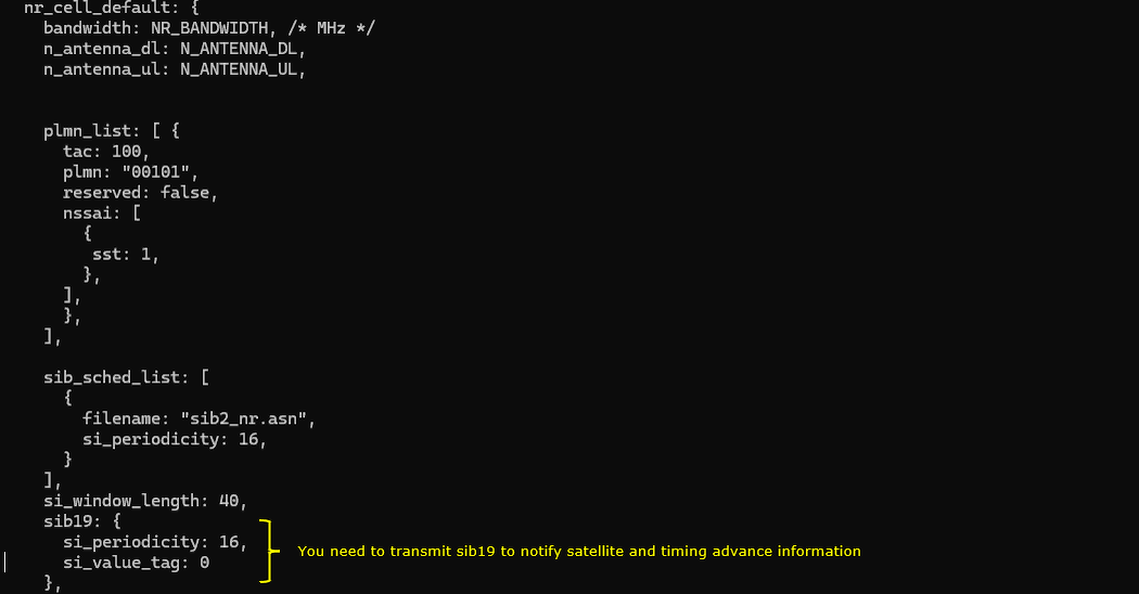
In nr_cell_default, bandwidth is configured by NR_BANDWIDTH, and the number of DL and UL antennas is configured by N_ANTENNA_DL and N_ANTENNA_UL. In this test, these values come from the common definitions shown earlier, so the cell uses 15 MHz bandwidth with one DL antenna and one UL antenna. The plmn_list defines the serving PLMN as 00101, with tac: 100 and one configured network slice using sst: 1.
sib_sched_list configures the normal SIB scheduling, and sib2_nr.asn is transmitted with si_periodicity: 16. The si_window_length is set to 40, which defines the time window where the UE can receive the scheduled SI message.
The important NTN-specific part is sib19. In NTN operation, SIB19 is required because it provides satellite-related assistance information and timing-related information to the UE. The UE uses this information to understand the NTN cell context and to apply the proper timing compensation for satellite access. In this example, sib19 is transmitted with si_periodicity: 16 and si_value_tag: 0, so the UE can acquire the NTN assistance information during system information acquisition.
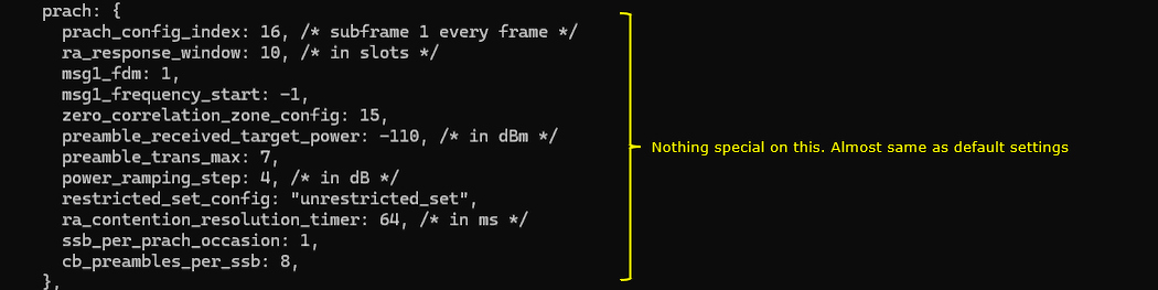
The PRACH configuration in this test is mostly based on normal default-style settings, so there is no special NTN-specific change in this part. prach_config_index: 16 defines the PRACH occasion pattern, and in this configuration it places the PRACH opportunity in subframe 1 of every frame. ra_response_window: 10 gives the UE 10 slots to wait for the Random Access Response after transmitting the preamble. msg1_fdm: 1 means one frequency-domain PRACH occasion is used, and msg1_frequency_start: -1 lets the system choose the PRACH frequency position automatically.
zero_correlation_zone_config: 15, preamble_trans_max: 7, power_ramping_step: 4, and restricted_set_config: "unrestricted_set" define normal PRACH preamble and retransmission behavior. preamble_received_target_power: -110 sets the target received power for PRACH at the gNB, and ra_contention_resolution_timer: 64 defines how long the UE waits for contention resolution after Msg3. ssb_per_prach_occasion: 1 and cb_preambles_per_ssb: 8 define the mapping between SSB and contention-based PRACH preambles. Overall, this PRACH block is not the main focus of the LEO NTN test; it mainly provides a standard random access configuration so the UE can perform initial access after acquiring the NTN cell and SIB information.
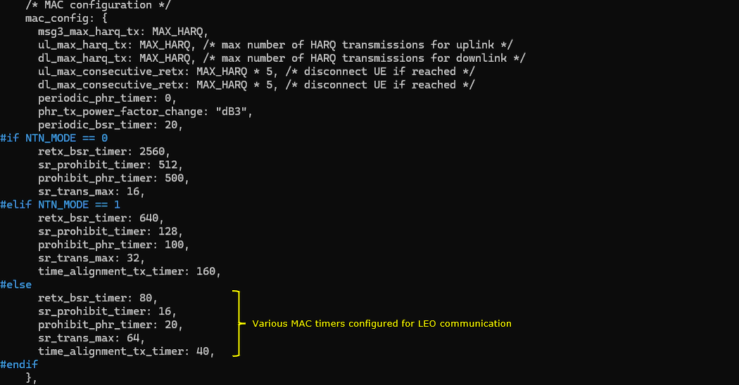
In the MAC configuration, the HARQ-related values are tied to MAX_HARQ, which was selected earlier based on the NTN mode. For this LEO test, MAX_HARQ is set to 5, so msg3_max_harq_tx, ul_max_harq_tx, and dl_max_harq_tx all allow up to 5 HARQ transmissions. ul_max_consecutive_retx and dl_max_consecutive_retx are set to MAX_HARQ * 5, so the UE is disconnected only after a larger number of consecutive retransmission failures. This gives the link enough tolerance for NTN timing and channel conditions.
The common MAC timers such as periodic_phr_timer: 0, phr_tx_power_factor_change: "dB3", and periodic_bsr_timer: 20 define normal power headroom and buffer status reporting behavior. Since this test uses LEO mode, the final conditional block is applied. retx_bsr_timer is set to 80, sr_prohibit_timer is set to 16, prohibit_phr_timer is set to 20, sr_trans_max is set to 64, and time_alignment_tx_timer is set to 40. These values are shorter than the GEO and MEO cases because LEO has lower propagation delay, but they are still adjusted for NTN operation compared with a normal terrestrial cell. Overall, this section configures the MAC layer timing behavior so that scheduling request, BSR retransmission, PHR reporting, HARQ retransmission, and time alignment can operate properly under the selected LEO NTN condition.
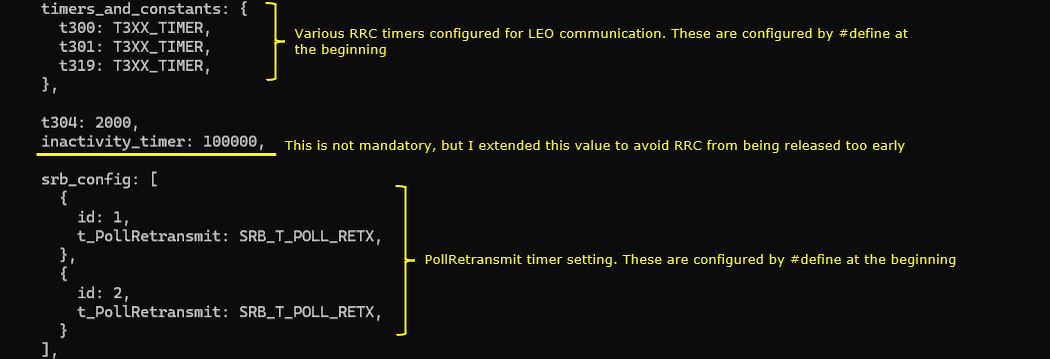
In this RRC configuration, t300, t301, and t319 are all set to T3XX_TIMER. For this LEO test, T3XX_TIMER was defined earlier as 1000, so these RRC timers are extended to provide enough margin for NTN operation. These timers control how long the UE waits during important RRC procedures such as connection setup, reconfiguration, or resume-related signaling, and using a larger value helps avoid premature timeout when satellite propagation delay and timing uncertainty are involved.
t304 is set to 2000, and inactivity_timer is set to 100000. The inactivity_timer extension is not mandatory, but it is useful in this test because it prevents the RRC connection from being released too quickly while checking NTN behavior. In the srb_config section, both SRB1 and SRB2 use t_PollRetransmit: SRB_T_POLL_RETX. For this LEO configuration, SRB_T_POLL_RETX was defined earlier as 80, so the SRB RLC retransmission polling behavior is also adjusted for the selected NTN mode. Overall, this section increases the tolerance of RRC and SRB signaling so the UE connection remains stable during the LEO NTN test.
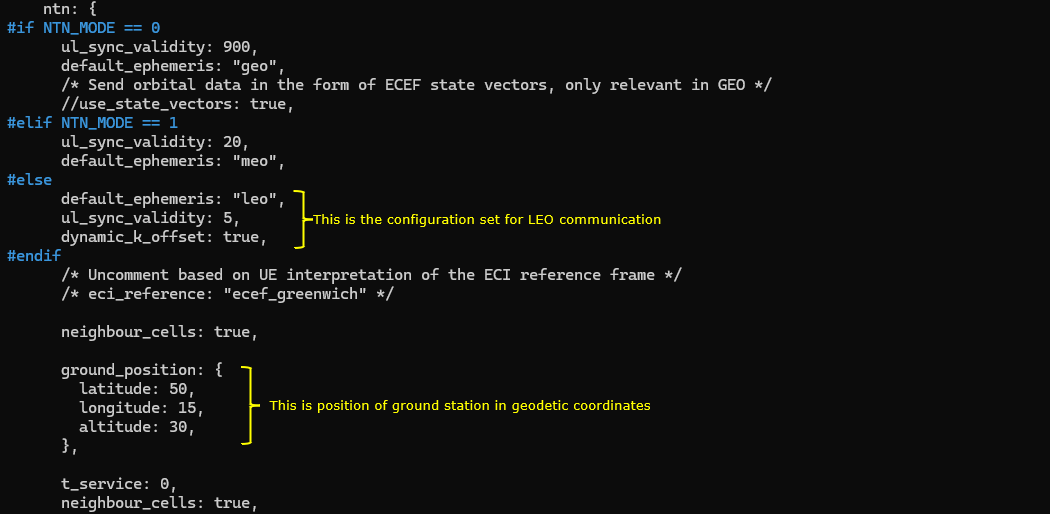
In the ntn configuration, the selected block depends on NTN_MODE. Since this test uses NTN_MODE 2, the LEO-specific block is applied. default_ephemeris: "leo" selects the default LEO satellite ephemeris model, ul_sync_validity: 5 defines how long the uplink synchronization information remains valid, and dynamic_k_offset: true enables dynamic K-offset handling. This is important for LEO because the satellite position and propagation delay change much faster than GEO or MEO, so the timing relationship between DL reception and UL transmission needs to be updated dynamically.
neighbour_cells: true enables neighbor cell information for the NTN scenario. The ground_position section defines the ground station position in geodetic coordinates, with latitude: 50, longitude: 15, and altitude: 30. This position is used as the reference location for the NTN model so that satellite geometry, propagation delay, and timing-related assistance information can be calculated consistently. Overall, this section is the main NTN configuration block for the LEO test, because it defines the satellite type, uplink synchronization validity, dynamic timing offset handling, and ground station location used by the cell.
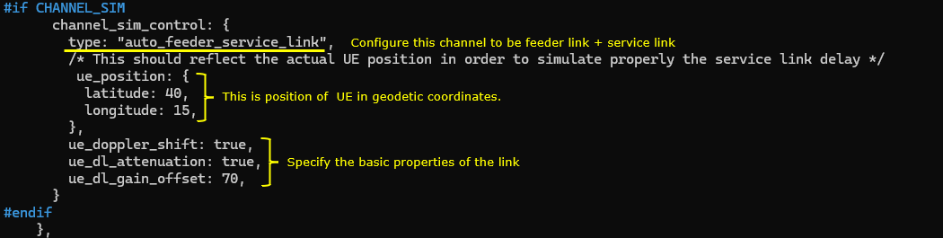
When CHANNEL_SIM is enabled, channel_sim_control defines how the satellite channel delay and link behavior are emulated. type: "auto_feeder_service_link" configures the simulator to include both the feeder link and the service link, so the overall NTN path reflects the ground station to satellite side as well as the satellite to UE side. This is important for LEO NTN testing because the total delay is not only determined by the UE side link, but also by the full satellite communication path used in the model.
ue_position defines the UE location in geodetic coordinates, with latitude: 40 and longitude: 15. This position should match the intended UE location for the test, because the service link delay depends on the geometry between the UE and the satellite. ue_doppler_shift: true enables Doppler shift emulation for the UE downlink, which is especially important for LEO because the satellite moves quickly relative to the UE. ue_dl_attenuation: true enables downlink attenuation modeling, and ue_dl_gain_offset: 70 applies an offset to the simulated downlink gain. Overall, this block configures the dynamic service-link behavior of the UE side, including UE location, Doppler, attenuation, and gain adjustment for the LEO NTN channel simulation.
ue-nr-ntn-once-cell.cfg is configured as follows
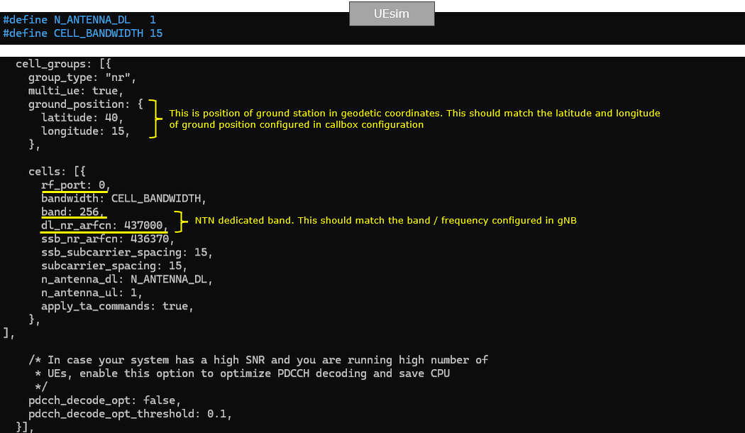
In the UEsim configuration, N_ANTENNA_DL is set to 1 and CELL_BANDWIDTH is set to 15, so the simulated UE expects a 15 MHz SISO NR cell. The cell group is configured as NR, and multi_ue: true allows the simulator to support multiple UEs if needed.
ground_position defines the ground station position in geodetic coordinates. In this example, latitude is set to 40 and longitude is set to 15. This position should be consistent with the NTN ground station position used in the Callbox configuration, because the NTN timing and propagation delay calculation depend on the relative geometry between the ground station, satellite, and UE.
Inside the cells section, rf_port: 0 maps the UE cell configuration to the first RF port, and bandwidth uses CELL_BANDWIDTH. band is set to 256, which is the NTN-dedicated band used for this test, and dl_nr_arfcn is set to 437000. These values should match the band and downlink frequency configured on the gNB side. ssb_nr_arfcn is set to 436370, and both ssb_subcarrier_spacing and subcarrier_spacing are set to 15. n_antenna_dl follows N_ANTENNA_DL, n_antenna_ul is set to 1, and apply_ta_commands: true allows the UE simulator to apply timing advance commands from the network. This is important in NTN testing because the uplink timing has to be continuously aligned according to the larger satellite-related propagation delay.
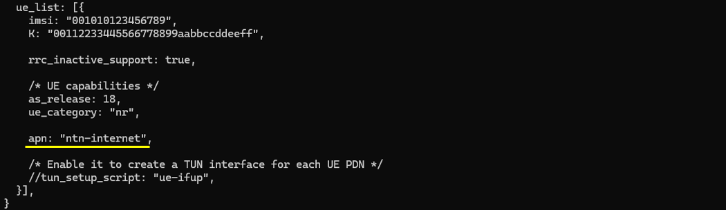
In the ue_list configuration, the simulated UE is defined with its IMSI and authentication key K, and these values should match the subscriber information configured on the core network side. rrc_inactive_support: true enables support for RRC Inactive operation, so the UE can support suspend and resume behavior if the network uses it.
The UE capability section sets as_release: 18 and ue_category: "nr", meaning this UE is treated as a Release 18 NR UE. This is suitable for NTN testing because NTN-related NR features are mainly associated with recent NR releases. The apn is set to "ntn-internet", so the UE will request this APN during PDU session establishment. If the core network is configured with the same APN, the UE can complete data session setup after registration.
The tun_setup_script line is commented out in this example. If it is enabled, UEsim can create a TUN interface for the UE PDN connection, which is useful when you want to send real IP traffic through the simulated UE. For this basic LEO NTN test, the main focus is not the TUN interface, but confirming that the UE can register and establish the NTN connection using the configured subscriber, capability, and APN settings.
Perform the test
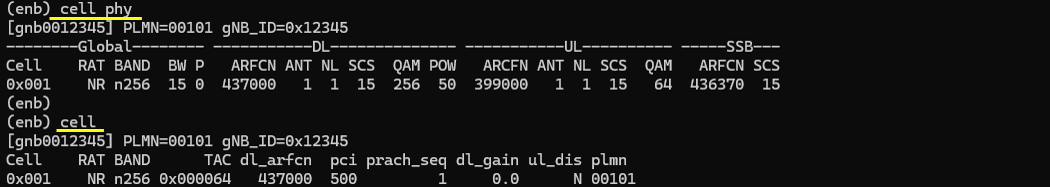
After starting the Callbox service, first check the configured cell using the cell_phy command. The output shows that the NR cell is running on band n256, which confirms that the cell is using the NTN-dedicated band configured earlier. The DL ARFCN is 437000, the SSB ARFCN is 436370, the subcarrier spacing is 15 kHz, the bandwidth is 15 MHz, and the antenna configuration is 1 DL antenna and 1 UL antenna, matching the SISO LEO NTN configuration used in this test.
Then run the cell command to check the higher-level cell configuration. The output shows the same NR n256 cell with TAC 0x000064, DL ARFCN 437000, PCI 500, PRACH sequence index 1, and PLMN 00101. These values confirm that the cell is broadcasting with the intended PLMN, tracking area, physical cell ID, and NTN band configuration. At this point, the Callbox side is ready, and the next step is to start UEsim and verify that the simulated UE can detect the NTN cell, apply the timing-related information, and proceed with registration.
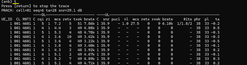
After the UE is started, run the t command on the Callbox to monitor the live PHY/MAC trace. The PRACH line shows that the gNB received a random access preamble from the UE, with seq=6, ta=28, and snr=29.1 dB. This confirms that the UE detected the NTN cell, transmitted PRACH, and the gNB was able to estimate the initial timing advance.
In the live trace table, the UE is assigned RNTI 4601 and continues to exchange downlink and uplink traffic with the cell. The DL side shows CQI values around 4 to 5, MCS values changing according to the link condition, and txok counts increasing, which means downlink scheduling and decoding are active. The UL side shows SNR around 35.9 dB and rxok counts, confirming that uplink transmission is also being received successfully. The ta column changes slightly around values such as -0.2, 0.5, -0.3, and 0.2, which indicates that timing alignment is being tracked and adjusted during the NTN connection. Overall, this trace confirms that the UE completed random access and that both DL and UL scheduling are running under the configured LEO NTN scenario.
Log Analysis
After confirming the basic cell configuration and live trace, the next step is to review the detailed log.
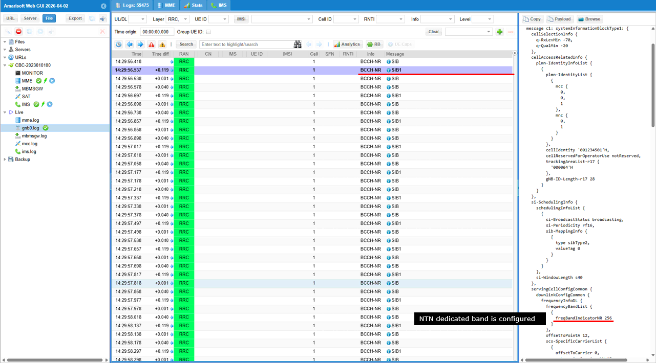
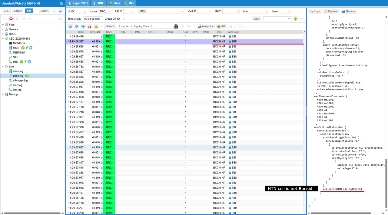
In the log, the first thing to check is SIB1. The repeated BCCH-NR SIB1 messages show that the cell is broadcasting system information normally, and the decoded payload confirms that the cell is configured as an NTN-capable cell. In servingCellConfigCommon, freqBandIndicatorNR is set to 256, which matches the NTN dedicated band used in the Callbox and UEsim configuration. This confirms that the UE is camping on the intended NTN NR cell, not on a normal terrestrial NR band.
The SIB1 payload also shows the NTN-related cell access information. In the nonCriticalExtension part, cellBarredNTN-r17 is set to notBarred, which means the NTN cell is allowed for UE access. This is an important check because even if the frequency and band are configured correctly, the UE cannot proceed with normal access if the NTN cell is barred. The same payload also includes the scheduled system information configuration for additional SIBs, so the UE can continue reading the NTN-related system information after acquiring SIB1.
Overall, this log confirms two important points at the beginning of the test: the cell is broadcasting on NTN band n256, and the NTN cell is not barred. This means the UE can treat this cell as a valid NTN cell and continue with system information acquisition, random access, and registration.
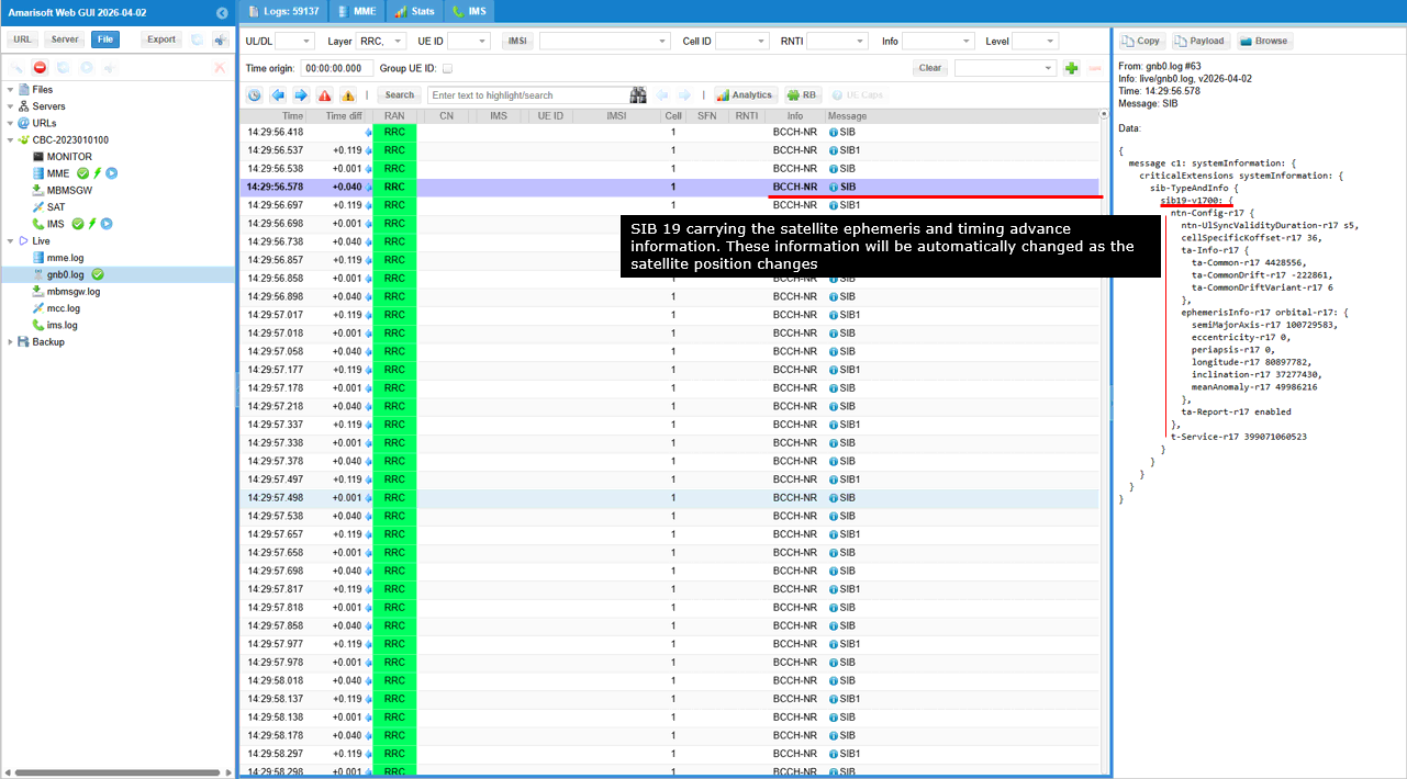
The next log item to check is SIB19. SIB19 is the key system information block for NTN operation because it carries the NTN assistance information required by the UE. In this example, the decoded SIB19 payload includes ntn-Config-r17, ntn-UlSyncValidityDuration-r17, cellSpecificKoffset-r17, ta-Info-r17, ephemerisInfo-r17, and t-Service-r17.
ntn-UlSyncValidityDuration-r17 is set to s5, which means the uplink synchronization information is valid for a short duration. This is suitable for LEO because the satellite position changes quickly and the UE should not rely on old timing information for too long. cellSpecificKoffset-r17 provides the cell-specific K offset used for NTN timing relationship between downlink and uplink. ta-Info-r17 includes ta-Common-r17, ta-CommonDrift-r17, and ta-CommonDriftVariant-r17, which provide the common timing advance and its variation over time. These values help the UE compensate for the large and changing propagation delay in the satellite link.
The ephemerisInfo-r17 field provides satellite orbit information, including parameters such as semiMajorAxis-r17, eccentricity-r17, periapsis-r17, longitude-r17, inclination-r17, and meanAnomaly-r17. The UE uses this information to understand the satellite position and its movement. Since this is a LEO scenario, these values are especially important because the satellite geometry and delay change continuously. t-Service-r17 indicates the service timing information related to the satellite service availability.
Overall, this log confirms that SIB19 is being broadcast and that the UE can receive NTN-specific satellite ephemeris, K-offset, and timing advance assistance information. This is one of the most important checks in the LEO NTN test because it verifies that the cell is not only configured on an NTN band, but is also providing the actual NTN system information required for UE access and uplink timing compensation.
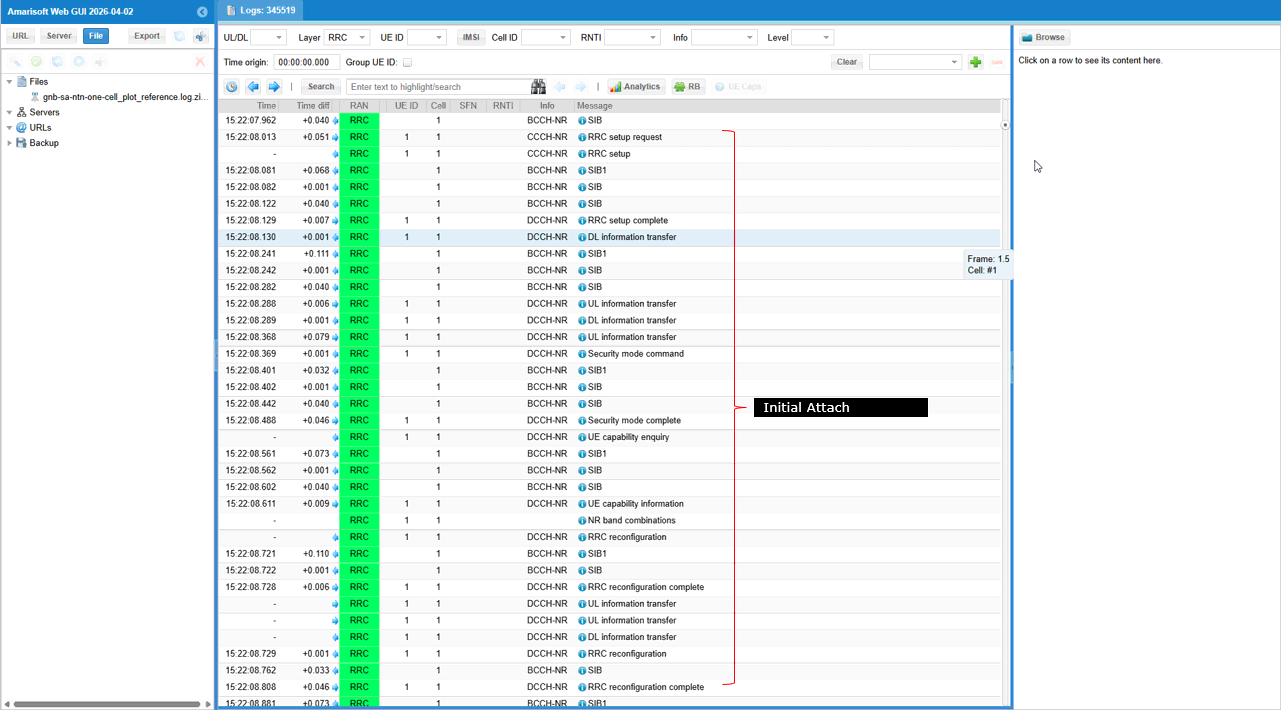
This log shows the initial attach signaling flow after the UE has acquired the NTN cell and completed random access. The sequence starts with RRC setup request, followed by RRC setup and RRC setup complete, which confirms that the UE successfully establishes the initial RRC connection with the gNB. After that, DL information transfer and UL information transfer messages carry the NAS signaling between the UE and the core network.
The log then shows security mode command and security mode complete, meaning NAS/RRC security activation is completed successfully. After security activation, the network sends UE capability enquiry, and the UE responds with UE capability information. This is followed by NR band combinations and RRC reconfiguration, where the gNB provides the final radio configuration for the connected UE. The UE then sends RRC reconfiguration complete, confirming that it accepted and applied the configuration.
Overall, this log confirms that the UE can proceed beyond NTN cell acquisition and random access into the normal registration and RRC configuration procedure. This is an important result because it shows that the NTN-specific SIB information and timing compensation are sufficient for the UE to maintain the signaling connection and complete the initial attach procedure over the configured LEO NTN scenario.
Following plots are from a separate log :
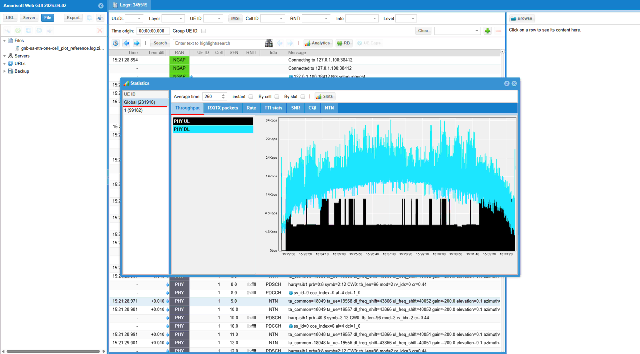
This screen confirms that the UE is not only attached, but also exchanging user-plane traffic after the NTN connection is established. In the Statistics window, the Throughput tab shows both PHY DL and PHY UL activity, which means downlink and uplink data are being scheduled during the test. The throughput is not the main target of this subtest, but the continuous PHY activity is useful evidence that the LEO NTN configuration is stable enough to carry traffic after registration.
In the background log, the PHY/NTN lines show continuously updated NTN timing information, including values such as ta_common, ta_ue, dl_freq_shift, ul_freq_shift, gain, elevation, and azimuth. These values are especially important for LEO because the satellite position changes over time, so timing advance and frequency shift compensation must also change dynamically. The presence of these NTN log lines indicates that the simulator is applying the LEO NTN channel model and updating delay and Doppler-related parameters during operation.
Overall, this result confirms the end-to-end behavior of the test. The UE acquires the NTN cell, reads SIB1 and SIB19, performs random access, completes initial attach, and then maintains DL/UL traffic while NTN timing and frequency compensation are updated in the background.
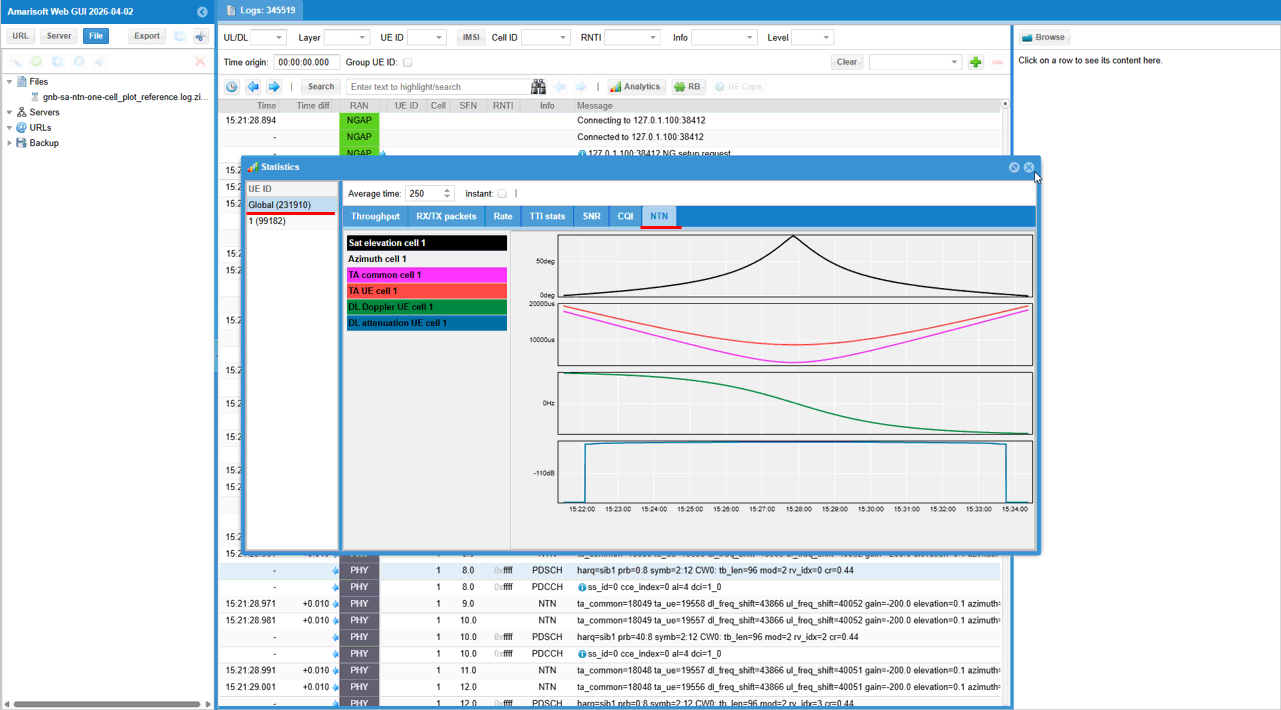
This NTN statistics view shows the satellite pass from horizon to horizon. In the NTN tab, the plotted values show how the LEO satellite geometry changes over time and how the simulator updates the radio parameters accordingly. The satellite elevation starts low near the horizon, increases as the satellite approaches the closest point, reaches the maximum elevation near the middle of the pass, and then decreases again as the satellite moves toward the opposite horizon.
The TA common and TA UE curves also change during the pass. They are large when the satellite is near the horizon because the propagation path is longer, then decrease as the satellite gets closer to the UE, and increase again as the satellite moves away. This is the expected behavior for a LEO satellite pass, and it confirms that the NTN timing model is dynamically updating the common timing advance and UE-specific timing advance.
The DL Doppler curve changes continuously as well. This reflects the relative motion between the LEO satellite and the UE. The Doppler shift is different before and after the closest approach because the satellite first moves toward the UE and then moves away from the UE. The DL attenuation curve also follows the satellite visibility period, showing the link condition over the pass.
Overall, this statistic view confirms that the test is emulating a complete LEO satellite pass, not just a fixed satellite position. From horizon to horizon, the simulator updates elevation, timing advance, Doppler shift, and attenuation, and this verifies that the UE is operating under a dynamic LEO NTN condition.
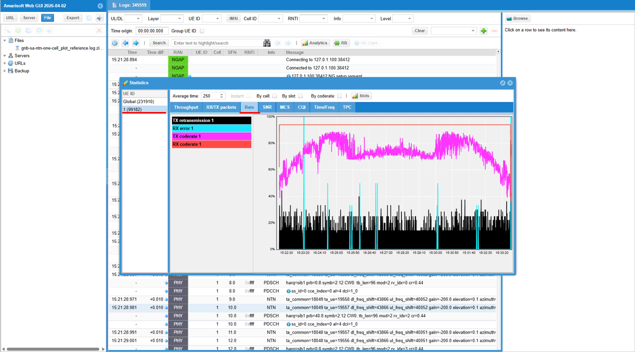
This RX statistics view shows how the link quality changes during the LEO satellite pass. The RX code rate curve changes over time, and it generally becomes better when the satellite is at a higher elevation because the propagation path is shorter and the link condition is more favorable. Near the beginning and end of the pass, when the satellite is closer to the horizon, the code rate becomes lower because the link condition is weaker.
The TX retransmission and RX error traces show that some retransmissions and decoding errors occur during the pass. This is expected in a dynamic LEO NTN scenario because delay, Doppler shift, attenuation, and timing advance are continuously changing as the satellite moves. The important point is not that the link is completely error-free, but that the system can continue operating while adapting to these changing radio conditions.
Overall, this statistic confirms that the UE is maintaining the connection across the satellite pass while the scheduler and link adaptation react to the NTN channel condition. The changing code rate, occasional retransmissions, and RX errors are consistent with a realistic LEO pass from horizon to horizon.
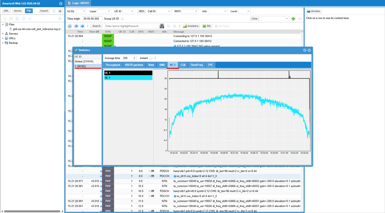
This MCS statistics view shows how the scheduler changes the modulation and coding scheme during the LEO satellite pass. The DL MCS increases as the satellite moves from the horizon toward a higher elevation angle, because the link condition becomes better and the scheduler can use a higher MCS. Near the middle of the pass, the DL MCS stays relatively high and stable, which matches the period where the satellite geometry is most favorable. After that, the MCS gradually decreases again as the satellite moves away toward the opposite horizon.
The UL MCS is mostly fixed at a high value in this view, while the DL MCS changes more visibly. This indicates that the downlink link adaptation is reacting to the changing NTN channel condition over the satellite pass. The small drops and fluctuations in the DL MCS are expected because Doppler, attenuation, timing advance, and received signal condition are continuously changing in a LEO scenario.
Overall, this result shows that the gNB scheduler is dynamically adapting the radio configuration during the horizon-to-horizon LEO pass. The MCS behavior is consistent with the satellite elevation trend: lower MCS near the horizon, higher MCS near the best visibility region, and lower MCS again as the satellite moves away.
Test 3 : NTN to TN Handover
This is to configure and test Handover from NTN to TN cell using Amarisoft UEsim as DUT. Overall scenario is illustrated as below. The UE (UEsim) establish the initial attach to NTN cell and switch (Handover) to TN Cell (i.e, gNB cell on the ground) as the satellite moves away from NTN gNB.
Configuration
The configuration shown here is common configuration for all the subtests belonging to Test 1 and I will not show this configuration repeatedly for every subtest.
I have used gnb-sa-tn-ntn-ho.cfg which is included in the default installation package on Callbox (gNB)

I am using mme-ims.cfg and ue_db-ims.cfg as they are.
On UEsim, I used ue-nr-tn-ntn-ho.cfg which is included in the default installation package on UEsim (

gnb-sa-tn-ntn-ho.cfg is configured as follows.
In gNB configruation, specify satellite orbit first with the test parameter NTN_MODE. You can select the type among GEO, MEO, LEO. In this test, GEO is selected. Once this parameter (NTN_MODE) is specified, various other test parameters are configured based on the selected NTN_MODE. CSI_SRS_PERIOD, MAX_HARQ, T3XX_TIMER, SRB_T_POLL_RETX are the parameters configured differently based on NTN_MODE. And CHANNEL_SIM is enabled to simulate the radio link between the ground station and satellite. Once NTN_MODE is selected, orbit-specific values such as CSI/SRS period, maximum HARQ retransmissions, RRC timer base (T3XX_TIMER), and SRB t-PollRetransmit are assigned using conditional defines so the rest of the configuration can reuse them consistently. In short, this block acts as the central NTN profile switchboard that sets orbit-aware timing and retransmission behavior before those values are consumed in MAC/RRC/cell configuration later in the file.

If CHANNEL_SIM is enabled, you can apply various channel profile to simulate the radio link between ground station and satellite. In this test, only awgn is applied. This configuration block enables the built-in channel simulator on the gNB side so the test can emulate the radio link between the ground station and satellite without using a real satellite path. When CHANNEL_SIM is enabled, a channel model is attached to the RF port configuration (rf_ports), and in this example the downlink channel profile is set to AWGN with a specified noise level (noise_level: -50). The main idea is that this provides a controlled baseline NTN test environment: the NTN procedures and timing behavior can be validated first with a simple impairment model before moving to more complex channel profiles or real over-the-air/satellite conditions.

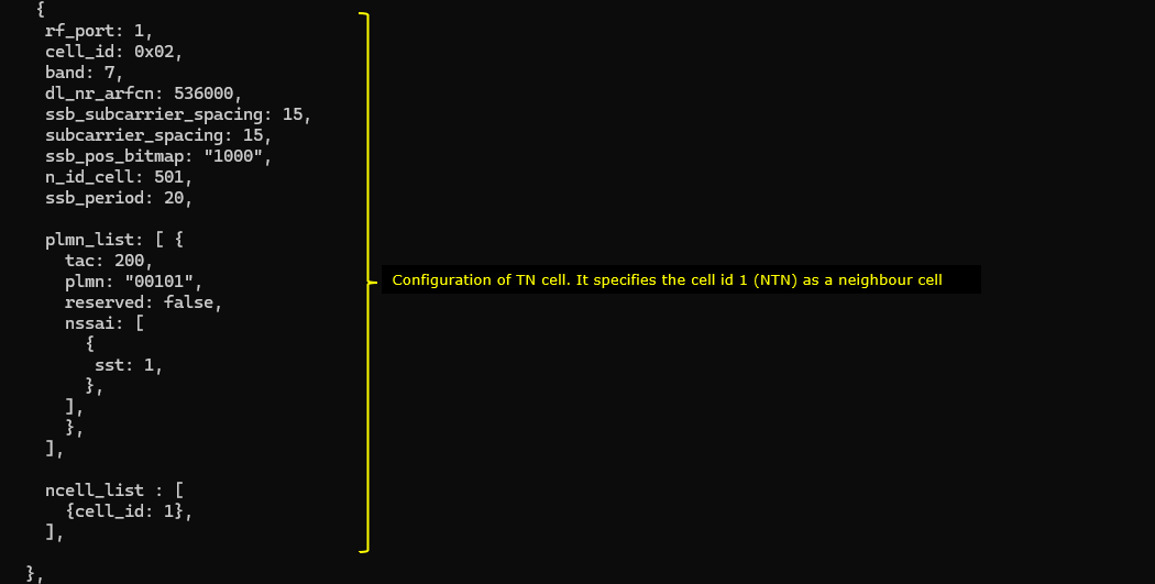
The first cell (the cell mapped to rf_port 0) is configured for ntn cell. NTN mode is set to GEO in this test and SIB19 is transmitted to broadcast ephemeris information of the cell. In this cell, the TN cell (cell_id 2) is configured as a neighbour cell(a handover destination candidates for this test). The nr_cell_list entry defines the cell identity, RF mapping, and radio parameters (band/ARFCN/SCS/SSB settings), and it also sets the SSB periodicity according to the selected orbit profile (GEO in this case). The plmn_list section defines the served PLMN/TAC and slice information, while the ntn block provides the NTN-specific parameters such as the default ephemeris type (geo), ground station position, and UE position (used especially when channel simulation is enabled to emulate feeder/service-link behavior and Doppler). In addition, the sib19 scheduling section is enabled so the gNB actually broadcasts NR NTN system information (including NTN configuration/ephemeris-related content) over the air. Overall, this is the core cell-level setup that turns a normal NR cell into an NTN test cell, combining radio settings, NTN geometry, and SIB19 broadcast configuration.

Followings are the simplified configuration
|
nr_cell_list: [ { rf_port: 0, cell_id: 0x01,
band: 256, dl_nr_arfcn: 437000, ssb_subcarrier_spacing: 15, subcarrier_spacing: 30, ssb_pos_bitmap: "1000",
ssb_period: 20, /* GEO */
n_id_cell: 500,
plmn_list: [ { tac: 100, plmn: "00101", reserved: false, nssai: [ { sst: 1 }, ], }, ],
ncell_list: [ { cell_id: 2, /* TN neighbour / HO target candidate for this test */ }, ], }, ],
ntn: { ul_sync_validity: 900, default_ephemeris: "geo",
ground_position: { latitude: 48.853, longitude: 2.348, altitude: 140, },
channel_sim_control: { type: "auto_feeder_service_link", ue_position: { latitude: 43.295, longitude: 5.373, altitude: 20, }, ue_doppler_shift: true, }, },
nr_cell_default: { sib_sched_list: [ { filename: "sib2_nr.asn", si_periodicity: 16, }, ], si_window_length: 40, sib19: { si_periodicity: 16, si_value_tag: 0, }, }, |
The cell mapped to rf_port1 is configured for the regular NR Cell (TN Cell). In this cell, the NTN cell (cell_id 1) is configured as a neighbour cell(a handover destination candidates for this test). In this setup, this cell acts as the normal serving NR cell, while the NTN cell (cell_id 1) is added in ncell_list as a neighbor cell / handover candidate. So the purpose of this block is to define the TN cell�s radio parameters (band/ARFCN/SCS/SSB), broadcast identity (PLMN/TAC), and neighbor relationship toward the NTN cell for mobility testing.
Followings are the simplified configuration
|
{ rf_port: 1, cell_id: 0x02,
// TN cell radio configuration band: 7, dl_nr_arfcn: 536000, ssb_subcarrier_spacing: 15, subcarrier_spacing: 15, ssb_pos_bitmap: "1000",
// Cell identity / SSB n_id_cell: 501, ssb_period: 20,
// Broadcast PLMN / TAC / slice info plmn_list: [ { tac: 200, plmn: "00101", reserved: false, nssai: [ { sst: 1 } ] } ],
// Neighbor cell list (NTN cell as HO candidate) ncell_list: [ { cell_id: 1 } ] } |
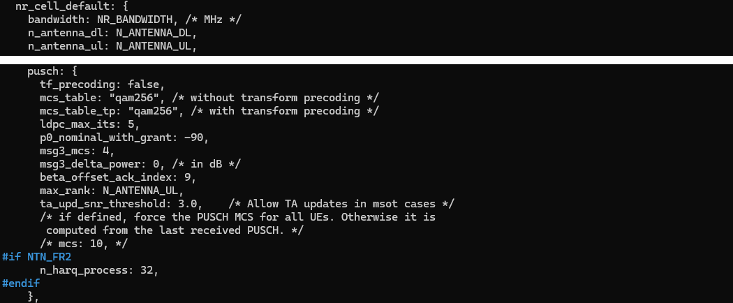
The default cell configuration (nr_cell_dfault) is very similar to regular NR to NR cell configuration except some specific configurations for NTN cell. This nr_cell_default block is basically the common NR baseline configuration shared by both a regular TN cell and an NTN cell, and then you add or override a few NTN-specific items where needed. In other words, most of the PHY/MAC/PUSCH behavior is still standard NR, so the same default structure is reused. The difference is that for NTN testing, some parameters are tuned to better tolerate long delay, larger timing uncertainty, and satellite-specific operating conditions. In the setup shown below, the pusch section is a good example of this approach: it keeps normal NR uplink settings (MCS tables, Msg3-related parameters, power-related settings, rank limits, TA update behavior), while adding an optional orbit/band-specific adjustment such as n_harq_process under #if NTN_FR2. So the idea is not to create a completely different nr_cell_default, but to start from regular NR defaults and selectively patch only the parameters that need NTN-aware behavior.
In MAC configuration (mac_config), various harq configurations (msg3_max_harq_tx, ul_max_harq_tx, dl_max_harq_tx) and retransmission configurations (ul_max_consecutive_retx,dl_max_consecutive_retx) are configured to accommodate the propagation dely of the NTN cell. In addition, some mac layer timers (retx_bsr_timer, sr_prohibit_timer, prohibit_phr_timer) are configured differently depending on the orbits of the satellite. This mac_config section is where the NTN cell is tuned so that MAC behavior can tolerate the much larger propagation delay of satellite links. The HARQ-related parameters such as msg3_max_harq_tx, ul_max_harq_tx, and dl_max_harq_tx are set to allow enough retransmission opportunities, and the consecutive retransmission limits (ul_max_consecutive_retx, dl_max_consecutive_retx) are also scaled so the UE is not disconnected too aggressively in a long-RTT environment. In addition to HARQ, MAC timers such as retx_bsr_timer, sr_prohibit_timer, and prohibit_phr_timer are adjusted by orbit type (NTN_MODE for GEO/MEO/LEO), because each orbit has a different expected RTT and timing behavior. As a result, GEO uses the longest timer values, while MEO and LEO use progressively shorter values. The same orbit-dependent idea is also applied to timers_and_constants (t300, t301, t319) so the RRC procedures remain stable and do not timeout prematurely under NTN propagation delay.
Followings are the simplified configuration
|
/* Simplified parameter setting (GEO example) */
mac_config: { /* HARQ / retransmission robustness for NTN */ msg3_max_harq_tx: 2, ul_max_harq_tx: 2, dl_max_harq_tx: 2, ul_max_consecutive_retx: 10, /* = MAX_HARQ * 5 */ dl_max_consecutive_retx: 10, /* = MAX_HARQ * 5 */
/* Common MAC settings */ periodic_phr_timer: 0, phr_tx_power_factor_change: "dB3", periodic_bsr_timer: 20,
/* GEO-specific timers (long RTT) */ retx_bsr_timer: 2560, sr_prohibit_timer: 512, prohibit_phr_timer: 500, sr_trans_max: 16 },
timers_and_constants: { /* GEO-specific RRC timers */ t300: 2000, t301: 2000, t319: 2000 },
srb_config: [ { id: 1, t_PollRetransmit: 800 }, { id: 2, t_PollRetransmit: 800 } ], |
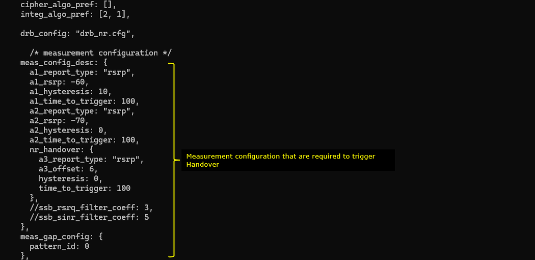
Then measurement configuration (meas_config_desc) should be configured to trigger the handover based on radio channel condition. It defines how the gNB evaluates radio quality and when it should trigger handover measurement reporting from the UE. It sets threshold-based events (A1/A2) to indicate when the serving cell is good enough or becoming weak, and it also defines the A3-based NR handover condition that compares the neighbor cell against the serving cell. In practice, this is the policy that tells the UE when to start reporting, what metric to use (here RSRP), and how stable the condition must be (hysteresis and time-to-trigger) before the report is considered valid. The meas_gap_config part defines the measurement gap pattern so the UE has time to measure the neighbor frequency/cell reliably during connected mode.
Followings are the simplified configuration
|
/* Measurement configuration to trigger HO based on radio condition */ meas_config_desc: { a1_report_type: "rsrp", a1_rsrp: -60, a1_hysteresis: 10, a1_time_to_trigger: 100,
a2_report_type: "rsrp", a2_rsrp: -70, a2_hysteresis: 0, a2_time_to_trigger: 100,
nr_handover: { a3_report_type: "rsrp", a3_offset: 6, hysteresis: 0, time_to_trigger: 100 },
},
meas_gap_config: { pattern_id: 0 }, |
ue-nr-tn-ntn-ho.cfg is configured as shown below. (
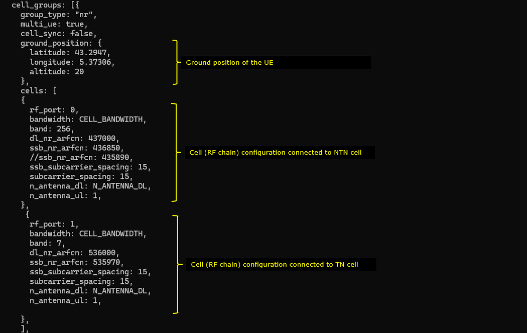
In UEsim configuration, you need to enable ntn functionality first by setting ntn:true and then configure the position of the UEsim. The position of UEsim is configured by the parameter ntn_ground_position and the ntn_ground_position on UEsim should match ue_position in gNB settings.

UEsim is configured with two RF chains (rf_port 0 and 1). The first RF chain (rf_port 0) is mapped to NTN Cell and the second RF chain (rf_port 1) is mapped to TN cell. This UEsim configuration defines a dual-cell NR test setup where one UE instance is prepared to interact with two different cells at the same time, using two separate RF chains. At the top level, the cell_groups block sets the group as NR, enables multi-UE support, and provides the UE ground position, which is important for NTN-related delay and Doppler modeling consistency. Inside the cells array, each entry represents one RF-chain-to-cell mapping: the first cell (rf_port: 0) is configured for the NTN cell (band 256), and the second cell (rf_port: 1) is configured for the terrestrial NR cell (band 7). Each cell entry carries its own frequency and SSB-related parameters (dl_nr_arfcn, ssb_nr_arfcn, SCS settings), so UEsim can synchronize and operate against both links correctly in the same scenario, which is useful for NTN/TN mobility or handover validation.
Followings are the simplified configuration
|
cell_groups: [{ group_type: "nr", multi_ue: true, cell_sync: false,
ground_position: { latitude: 43.2947, longitude: 5.37306, altitude: 20 },
cells: [ { /* NTN cell on RF port 0 */ rf_port: 0, bandwidth: CELL_BANDWIDTH, band: 256, dl_nr_arfcn: 437000, ssb_nr_arfcn: 436850, ssb_subcarrier_spacing: 15, subcarrier_spacing: 15, n_antenna_dl: N_ANTENNA_DL, n_antenna_ul: 1 },
{ /* TN cell on RF port 1 */ rf_port: 1, bandwidth: CELL_BANDWIDTH, band: 7, dl_nr_arfcn: 536000, ssb_nr_arfcn: 535970, ssb_subcarrier_spacing: 15, subcarrier_spacing: 15, n_antenna_dl: N_ANTENNA_DL, n_antenna_ul: 1 } ] }] |
Then you need to set as_release 17 since NTN is supported from release 17 and specify the apn name that you want to use for this test. (
Perform the Test
Run lte service on callbox and then check 'cell phy' and 'cell' command. Make it sure that cell is configured as you intended. In this test, n256 is used because it is the band allocated for NTN by 3GPP, but in terms of the equipment capability it can support any band for NTN test.

This is not the mandatory process.. but I did this to collect SIB message in the log for a few seconds at the beginning. I did bcch=1 and after a few seconds did bcch=0.
![]()
Now start trace logging.
![]()
Power on UE on UEsim (If your DUT is a commercial phone, turn on the phone)
Wait until the DUT complete the initial attach. (

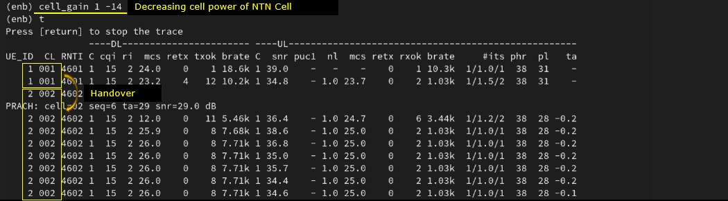
Once UEsim is in connection with NTN cell, reduce the cell power to trigger the handover . This step is a practical way to force the UE to leave the NTN cell and move to the neighbor TN cell for handover verification. After the UE is stably connected on the NTN cell, the Callbox command cell_gain 1 -14 is used to reduce the transmit power of the NTN cell (cell ID 1 in this example) by 14 dB. As the NTN serving cell signal quality drops, the UE measurements cross the handover thresholds configured earlier, and the handover procedure is triggered toward the target cell. In the trace, you can see the UE context move from the original cell to the target cell, which confirms that the measurement configuration and neighbor-cell settings are working together correctly. The exact gain reduction needed is not fixed; it depends on RF conditions, channel simulation settings, fading/noise, and relative power balance between the NTN and TN cells.
Log Analysis
Following is the log snapshot that are involved in communication with NTN and Handover to TN cell.
First thing to note is measurement configurations to detect appropriate channel condition to complete the handover.
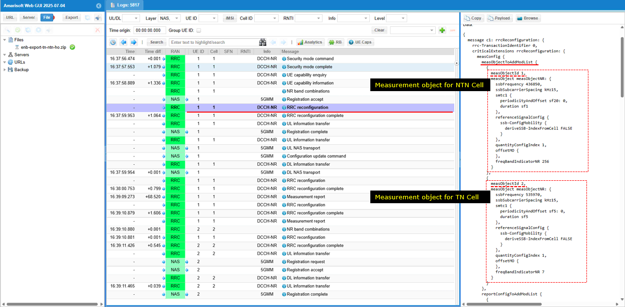
RRC Reconfiguration message configures two measurement objects. It configures two measurement object - measObjectId 1 for an NTN cell (measObjectNR) with frequency 436580 (ssbFrequency) and measObjectId 2 for a terrestrial TN cell (measObjectNR) with frequency 359700 (ssbFrequency). Each object includes SSB subcarrier spacing (ssbSubcarrierSpacing), periodicity/offset (periodicityAndOffset), reference signal config (referenceSignalConfig), and frequency band indicators (freqBandIndicatorNR).
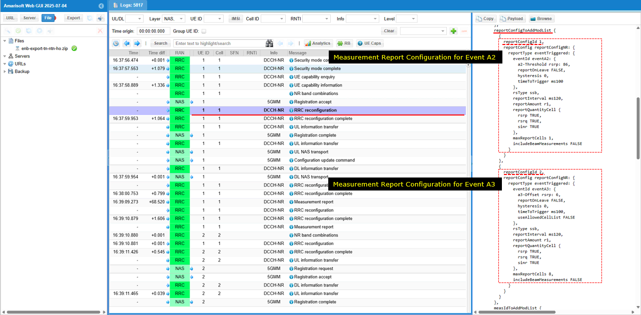
It configures two measurement report objects (reportConfigToAddModList) - reportConfigId 1 for Event A2 (eventTriggered → eventId: eventA2), including threshold RSRP (a2-Threshold-rsrp), hysteresis (hysteresis), report interval (reportInterval), and report quantity (reportQuantityCell). It also lists reportConfigId 2 for Event A3 (eventTriggered → eventId: eventA3), including offset RSRP (a3-Offset-rsrp), report interval (reportInterval), report amount (reportAmount), and reporting cells (maxReportCells).
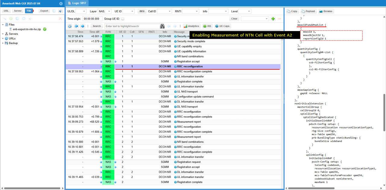
The same message configures the association between a measurement object and a reporting event. In the section measIdToAddModList, entry measId 1 links measurement object 1 (measObjectId 1, corresponding to the NTN cell) with report configuration 1 (reportConfigId 1, corresponding to Event A2). This enables measurement of the NTN cell under the Event A2 reporting condition.
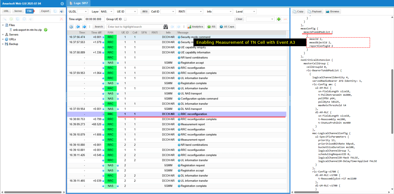
When the condition is met, gNB configures another measurement item : entry measId 2 which links measurement object 2 (measObjectId 2, corresponding to the TN cell) with report configuration 2 (reportConfigId 2, corresponding to Event A3). This enables measurement of the TN cell under the Event A3 reporting condition.
A Measurement Report (measurementReport) sent by the UE after Event A2 was triggered. The report contains the field measResults contains measId 1 (linked to Event A2), and measResultServingMOList includes serving cell results. Within it, measResultServingCell reports PCI (physCellId 500) with measurement values of rsrp, rsrq, and sinr.
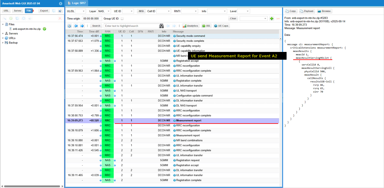
After the first expected measurement report, gNB send RRC Reconfiguration (rrcReconfiguration) that configures both a new reporting event and a measurement gap. In reportConfigToAddModList, reportConfigId 1 is defined for Event A1 (eventId: eventA1) with threshold RSRP (a1-Threshold-rsrp), hysteresis (hysteresis), reporting interval (reportInterval), and report quantity (reportQuantityCell). Below, in measGapConfig, the field gapUE with setup specifies measurement gaps, including gapOffset 16, mgta ms8, and related parameters, enabling the UE to perform inter-frequency/inter-RAT measurements.
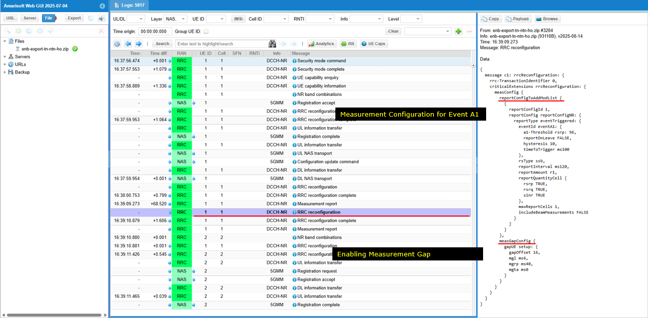
When the certain radio condition is met, the UE send Measurement Report (measurementReport) for Event A3. In the measurement report, measResults contains measId 2 (linked to Event A3). The field measResultServingMOList reports serving cell results (servCellId 0, physCellId 500) with measurements value of rsrp, rsrq, sinr. Additionally, measResultNeighCells (measResultListNR) reports a neighboring cell (physCellId 501) with values of rsrp, rsrq, sinr. This indicates the UE is evaluating handover conditions by comparing serving and neighbor cell quality.
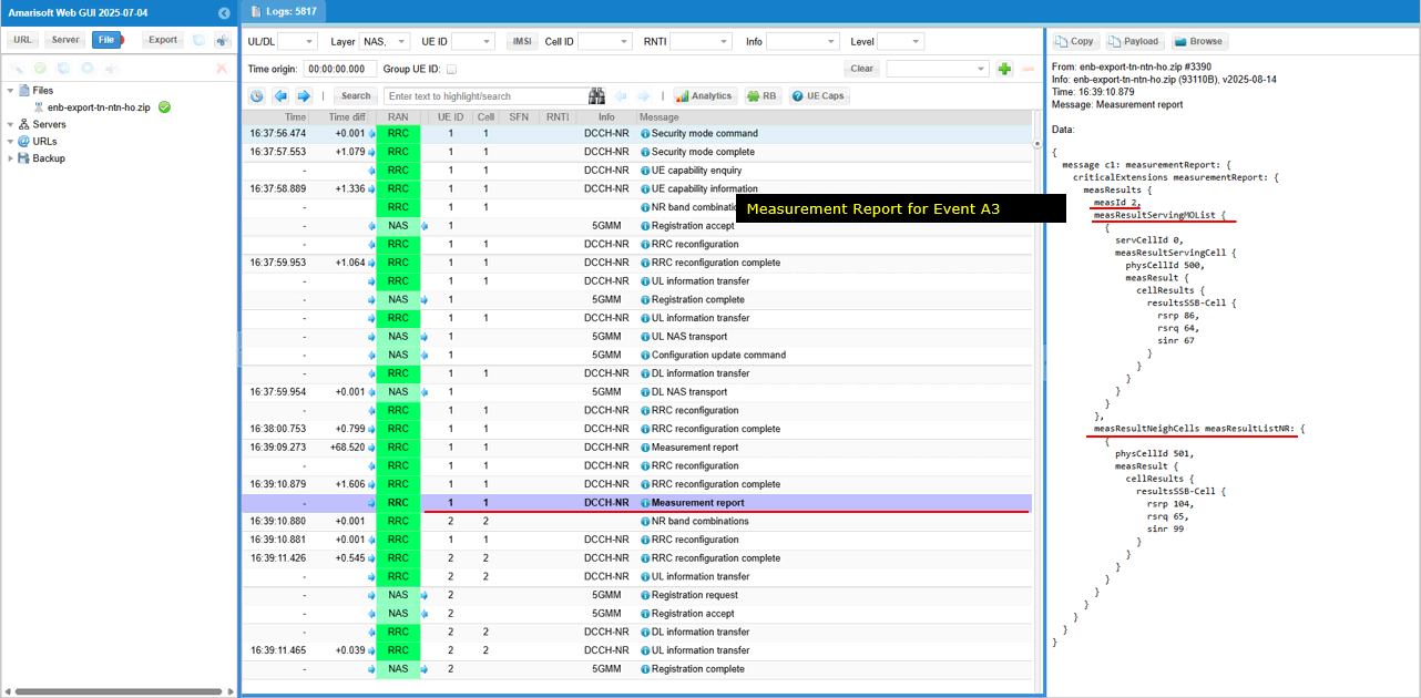
On the reception of the expected measurement report, gNB sends RRC Reconfiguration (rrcReconfiguration) that triggers a handover. In the message, the target cell is identified by physCellId 501, which corresponds to the terrestrial TN cell. The configuration includes downlinkConfigCommon with carrier frequency (frequencyInfoDL), absoluteFrequencySSB , subcarrierSpacing , and carrierBandwidth . This indicates the UE is instructed to hand over from its current serving cell(NTN cell) to the new physical cell ID 501 on the TN network.
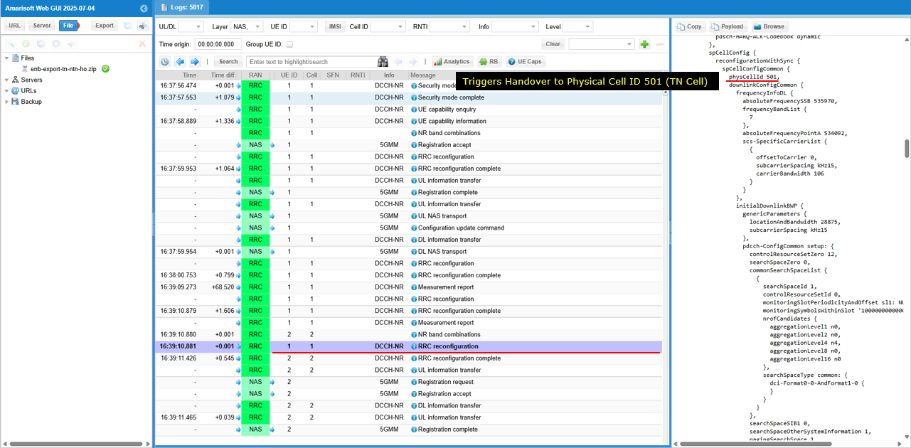
Test 4 : Conditional Handover
Amarisoft support Conditional Handover for NTN as well. CHO for NTN is covered in a separate tutorial referenced below
- NTN SA Inter Frequency Conditional Handover - with Event D1
- NTN SA Inter Frequency Conditional Handover - with Event T1
RRC / NAS Signaling
SIB19 (NR)
: This is SIB19 containing ephemeris
{
message c1: systemInformation: {
criticalExtensions systemInformation: {
sib-TypeAndInfo {
sib19-v1700: {
ntn-Config-r17 {
ntn-UlSyncValidityDuration-r17 s240,
cellSpecificKoffset-r17 520,
ta-Info-r17 {
ta-Common-r17 62210800
},
ephemerisInfo-r17 orbital-r17: {
semiMajorAxis-r17 8394210402,
eccentricity-r17 0,
periapsis-r17 0,
longitude-r17 248299011,
inclination-r17 0,
meanAnomaly-r17 533258
}
}
}
}
}
}
}
FAQ
I am putting a list of frequently asked questions and answers that would help everybody.
[Q1] why we need channel simulator ?
[A1] It is necessary to simulate the constantly changing real time position of the satellite
[Q2] do we always need to use the channel simulator ?
[A2] Yes for MEO or LEO in which delay and doppler varies relatively in large scale. Maybe optional to GEO in which delay and doppler does not vary widely. (NOTE : You may use the internal channel simulator at the testing phase in quick and easy way, but you can also use an external satellite channel simulator as well).
[Q3] What is the maximum delay simulated by Amarisoft Channel Simulator ?
[A3] Up to several seconds. The maximum value will depend on the sample rate, the value is max_delay in s = 2.147e9 / (sample_rate in Hz). In NB-IoT, for example, the sample rate is usually 1.92 MHz, so the max_delay is around 1118 seconds.
[Q4] What is the minimum configurable altitude of a satellite ?
[A4] The 3GPP encoding for the semi-major axis has a minimum of 6500 km, so a minimum of 122(=6500-6378) km altitude, where 6378 is the radius of the earth
[Q5] For ue_position, ground_position, we allow the altitude with the range of -1000m to 20km, what is the reason to allow negative values ?
[A5] It is to configure altitude below sea level. (https://en.wikipedia.org/wiki/List_of_places_on_land_with_elevations_below_sea_level )