LTE D2C (Direct To Cell)
This tutorial is to show you how to configure and test Direct to Cell in LTE. Direct to Cell represents 'From Satellite directly to Cellular Phone'. The 'Cellular Phone' in this context is just an ordinary commercial mobile hone that you have and it does not need to support any special feature for satellite communication as long as it works with ordinary NR SA in terrestrial network.
Actually Direct To Cell is not the 3GPP based feature like NTN (NB NTN or NR NTN). So the UE is not expected to support any specific features to accommodate this type of connection. So all the functionality to handle such a long delay or doppler shift etc which are present for satellite communication should be implemented by gNB that is sitting on the Satellite. This gNB implementation is mostly up to gNB vendor since the functionality is not specified in 3GPP.
Table of Contents
Introduction
Direct to Cell in LTE represents a transformative approach in wireless communications by enabling standard commercial cellular phones to directly connect to satellites, bypassing the need for specialized satellite-compatible hardware within the user equipment (UE). Unlike traditional satellite communication systems, which often require purpose-built devices or custom firmware, Direct to Cell leverages the existing capabilities of LTE (Long Term Evolution) technology, allowing ordinary mobile devices that function in terrestrial NR SA (New Radio Standalone) environments to seamlessly access satellite-based networks. This innovation is distinct from 3GPP-defined Non-Terrestrial Network (NTN) solutions—such as NB-IoT NTN and NR NTN—because it does not rely on explicit protocol or feature support from the UE. Instead, the responsibility for managing the unique challenges of satellite communication, including long transmission delays and significant Doppler shifts, is handled entirely at the network side by the gNB (Next Generation NodeB) located on the satellite. The design and implementation of these satellite-based gNBs remain largely proprietary, as 3GPP specifications do not standardize the mechanisms for compensating satellite-specific impairments in this context. As a result, Direct to Cell serves as a practical and highly accessible means to extend cellular coverage globally, leveraging the pervasive LTE ecosystem without necessitating changes to end-user devices, and plays a pivotal role in bridging the digital divide in remote or underserved regions.
-
Context of Direct to Cell in LTE
- Direct to Cell enables ordinary commercial mobile phones to connect directly to satellites using standard LTE protocols.
- The technology extends LTE connectivity beyond terrestrial boundaries, reducing the necessity for specialized satellite-capable handsets.
- Unlike 3GPP-defined NTN solutions, Direct to Cell is not based on standardized features or message structures for satellite support within the UE.
-
Relevance and Importance of the Tutorial
- This tutorial provides step-by-step guidance on configuring and validating Direct to Cell connectivity in LTE networks.
- Understanding how to implement and test this technology is essential for network engineers, system integrators, and researchers interested in expanding coverage to remote or underserved areas using existing mobile devices.
- The tutorial highlights architectural considerations and best practices for adapting LTE infrastructure to operate efficiently in satellite environments.
-
Learning Outcomes
- Gain a comprehensive understanding of the Direct to Cell concept and its distinction from standardized NTN architectures.
- Learn how gNBs on satellites compensate for satellite-specific challenges such as increased latency and Doppler effects.
- Acquire practical skills for configuring, deploying, and testing LTE Direct to Cell connections.
- Develop insight into the broader significance of Direct to Cell in expanding mobile connectivity and its implications for the future of wireless communication.
-
Prerequisite Knowledge and Skills
- Familiarity with LTE network architecture, including the roles of UE, eNB/gNB, and the core network.
- Basic understanding of radio access technologies and satellite communication fundamentals.
- Experience with LTE configuration, network testing, and troubleshooting tools is beneficial for hands-on sections.
Summary of the Tutorial
This tutorial details the procedure for configuring and testing Direct to Cell (D2C) functionality with a simulated Low Earth Orbit (LEO) satellite using Amarisoft eNB and UEsim as the Device Under Test (DUT). The focus is on low-layer testing, with minimal IP layer configuration required.
-
Test Setup:
- The SIM card supplied with the system is used as-is.
- Two different setups are possible with Amarisoft eNB and UEsim, but the configuration is based on the [B] setup as illustrated.
-
Key Configuration Parameters:
- Critical parameters include satellite, ground station, and UE locations (using default_ephemeris, ground_position, and ue_position), channel simulation settings, timing advance, Doppler compensation, frequency settings, and band/channel configuration. All these are set primarily under the ntn parameter group.
- No special satellite configuration is needed for the UE, since Direct to Cell is designed for operation with standard UE.
-
Test 1: D2C with Simulated LEO and UEsim
-
Configuration Steps:
- eNB: Use
enb-dtc.cfgwith Channel Simulation enabled (CHANNEL_SIM = 1). SAT_ALTITUDE is set to define satellite altitude. - Only constant delay is applied in the channel profile for simplicity.
- LTE FDD band (e.g., Band 7) is used; ensure band and channel (dl_earfcn) match between eNB and UE.
- SIB message is specially configured to accommodate longer propagation delays (e.g., timer values, RACH configuration).
- NTN-specific settings: Satellite, ground station, and UE locations are configured under the ntn section using appropriate parameters.
-
UEsim: Use the default configuration file (
ue.default.cfg). No special configuration is required for satellite operation, except to match band and channel to the eNB. - UE list configuration remains as default.
- eNB: Use
-
Test Execution Steps:
- Start the LTE service on the callbox and verify cell configuration using the 'cell phy' and 'cell' commands.
- Optionally, enable and then disable BCCH logging to capture SIB messages at the start.
- Begin trace logging.
- Power on the UE on UEsim (or commercial phone if used as DUT).
- Wait for the DUT to complete the initial attach process.
- Generate data traffic (e.g., ping) to verify data connectivity. Check for expected TTL values reflecting long propagation delay.
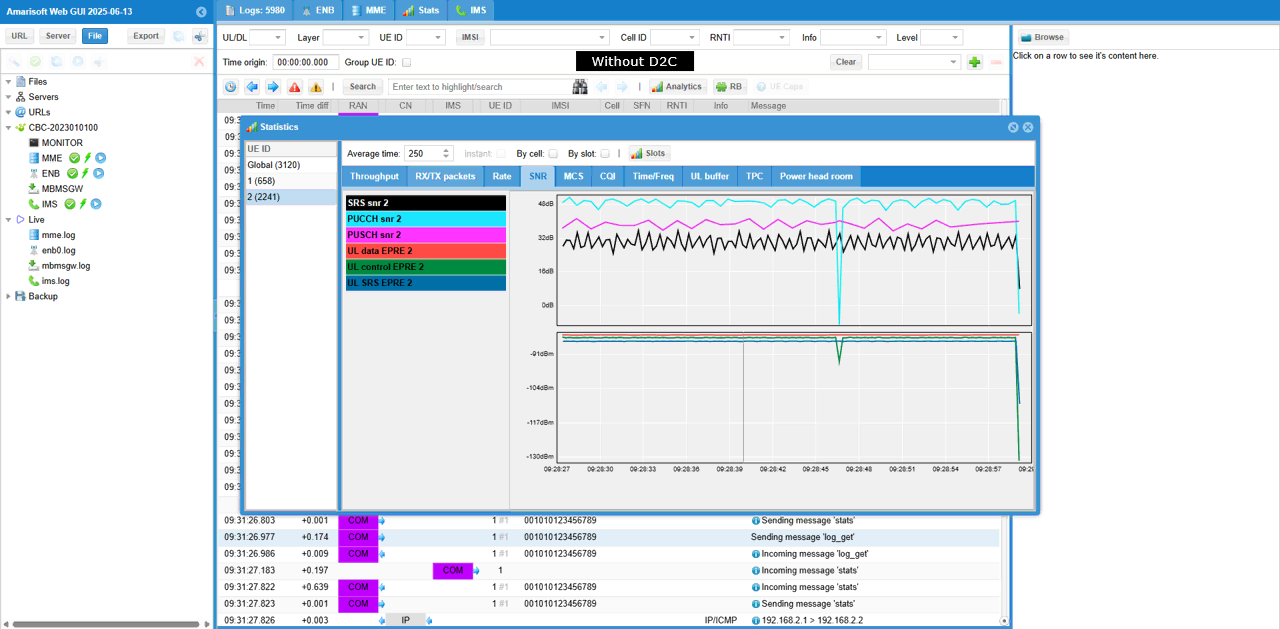
- Comparative tests can be performed using a commercial UE and/or with D2C disabled to observe differences, especially in TTL values.
-
Log Analysis and Monitoring:
- Use WebGUI to monitor the real-time positions of eNB and UE, and check satellite visibility (elevation and distance values).
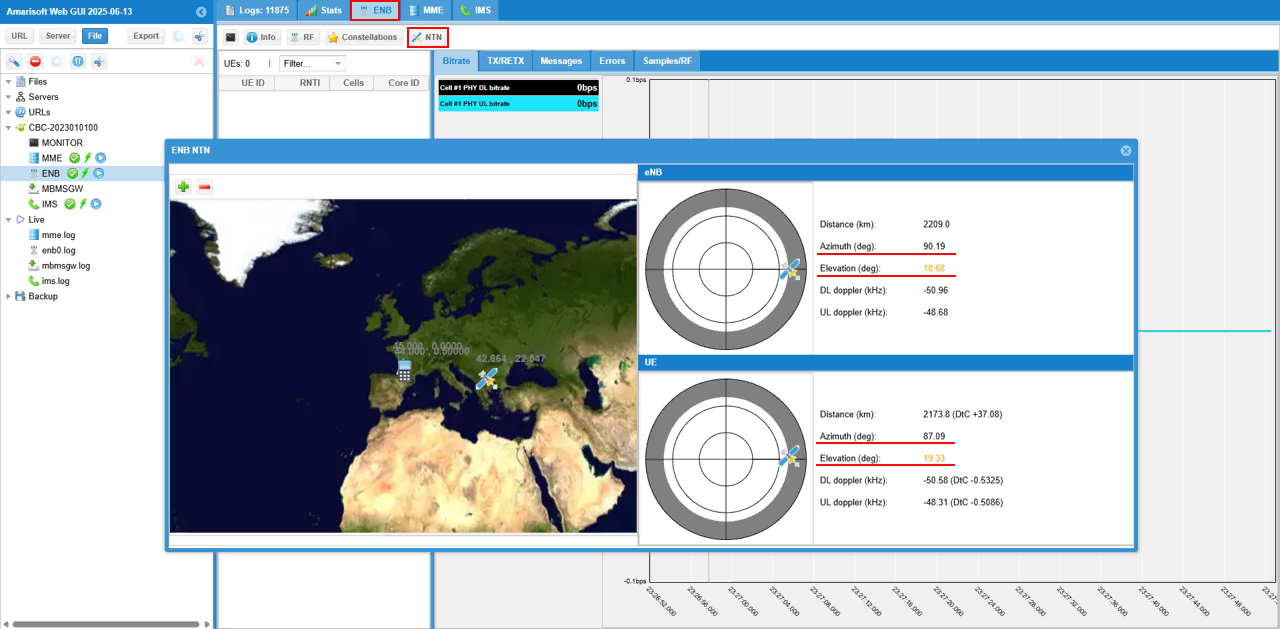
- If position values (Azimuth or Elevation) turn orange, this indicates loss of satellite visibility and connection drop.
- No significant differences in signaling between D2C and standard terrestrial communications, except for adjustments in RACH configuration and timers for long delay.
- Special RACH procedure: Multiple consecutive RACH attempts (4 in this example) are used to handle large propagation delay. The eNB is modified to send multiple RAR messages per PRACH occasion.
- Verify that the attach process completes successfully.
- Check throughput by running continuous ping and monitoring data flow.
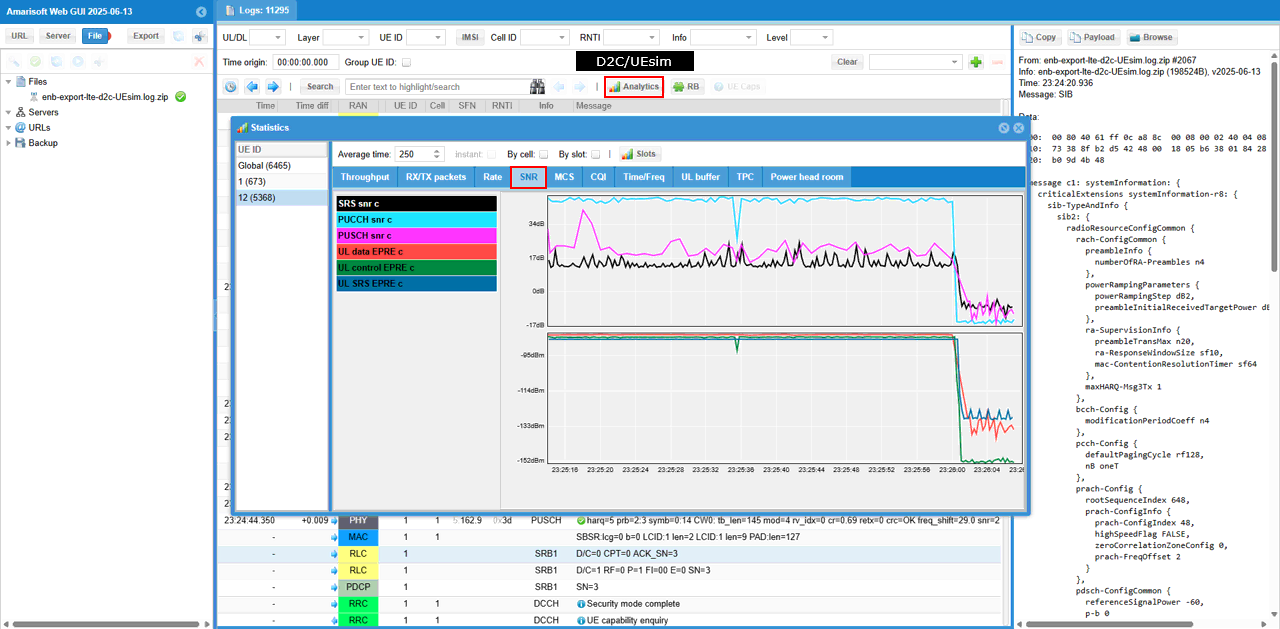
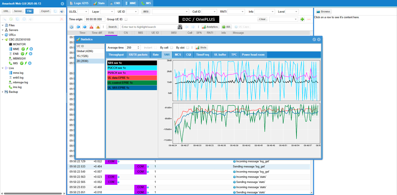
- Monitor SNR plots and compare signal quality over the test period (noting connection type: conductive with UEsim, radiative with commercial UE).
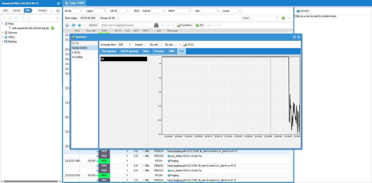
- Review DL CQI plots for signal quality as perceived by the UE.
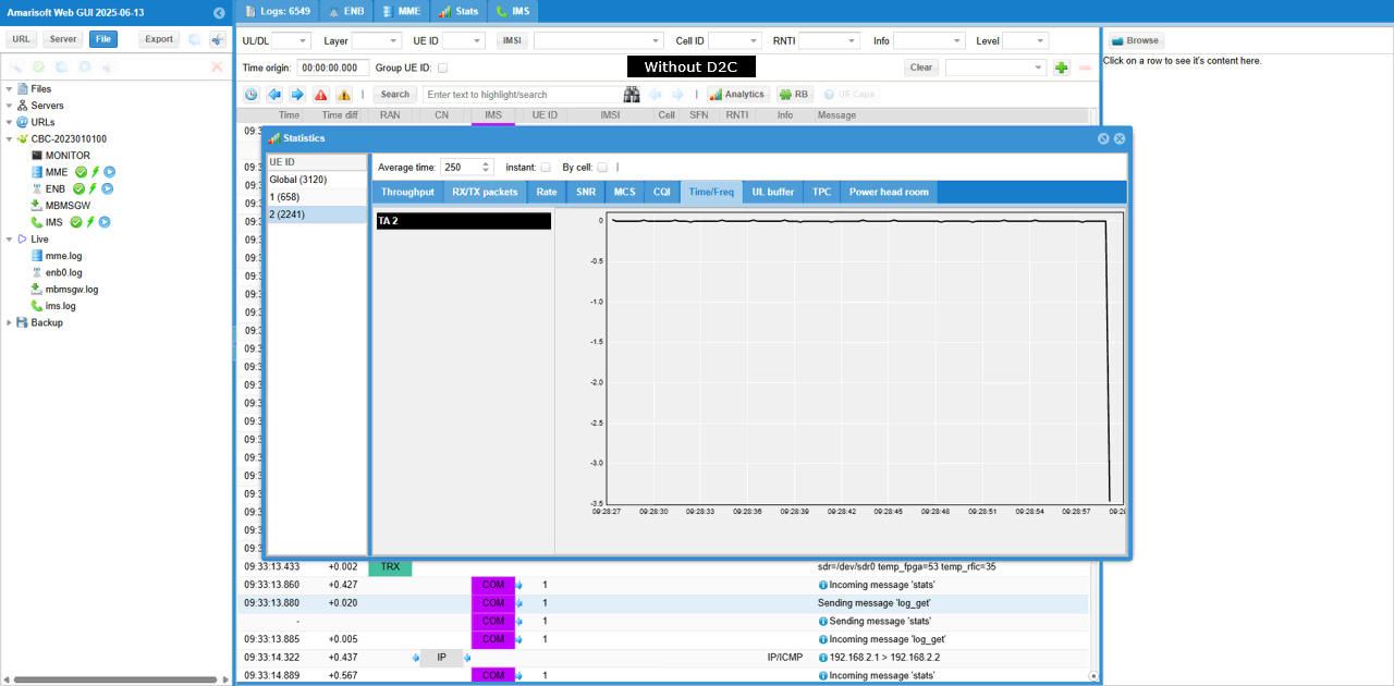
- Inspect Timing Advance (TA) command values to assess propagation delay handling. Comparative analysis can be performed with and without D2C enabled.
-
Configuration Steps:
Overall, the methodology emphasizes careful configuration of channel simulation and NTN parameters, verification of physical and logical cell setup, data path validation, and comprehensive monitoring of radio and network layer performance, with comparative analysis between D2C and non-D2C scenarios as well as different DUT types.
Test Setup
Test setup for this tutorial is as shown below. This is just for low layer testing, you may not need any complicated IP layer setup.
- SIM Card used in this tutorial is the one delivered with the system as it is.
- If you want to change the configuration, The tutorial Configuration Guide would help
With Amarisoft eNB and UEsim, we can try with following two different setups.

Key Configuration Parameters
Followings are important configuration parameters for this tutorial. You may click on the items for the descriptions from Amarisoft documents.
- ntn : In this link, you can find the descriptions for all the parameters below.
- ephemeris
- use_state_vectors
- eci_reference
- ground_position
- n_ta_common
- n_ta_drift
- n_ta_drift_var
- n_ta_common_offset
- feeder_doppler_compensation
- feeder_dl_freq
- feeder_ul_freq
- large_freq_shift
- direct_to_cell
- channel_sim_control
- type
- ue_position
- ue_doppler_shift
- ue_dl_freq
- ue_ul_freq
- feeder_doppler_shift
- ue_dl_attenuation
- ue_dl_gain_offset
- ul_sync_validity
- k_offset
- k_mac
- dynamic_k_offset
- reference_location
- t_service
- neighbour_cells
- rat_type
- t318
Test 1 : D2C with Simulated LEO and UEsim
This is to configure and test Direct to Cell for Simulated LEO using Amarisoft UEsim as DUT.
Configuration
The configuration shown here is common configuration for all the subtests belonging to Test 1
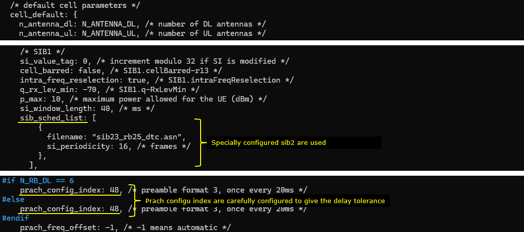
I have used enb-dtc.cfg for eNB. In this configuration, specicialy configured SIB message sib23_rb25_dtc.asn is used.

I am using mme-ims.cfg and ue_db-ims.cfg as they are.

On UEsim, I used ue.default.cfg as it is

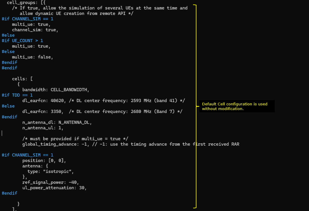
enb-dtc.cfg is configured as follows.
eNB configruation is very similar to the default enb configuration. The important thing is to enable Channel Sim(CHANNEL_SIM = 1). You can set the altitude of the satellite by setting SAT_ALTITUDE.

If CHANNEL_SIM is enabled, you can apply various channel profile to simulate the radio link between ground station and satellite. In this test, only constant delay is applied for simplicity.

An LTE FDD band is configured for this tutorial. This is same as the default configuration for most of the sample config file.

In this test, a specially configured SIB message is used (mainly for setting timer values to accommodate the long distance case). and you may need to tweak prach_config_index to accommodate the long distance situation.
Now for the configurations specific for ntn. The configuration parameter name itself is ntn. In this parameter, you can specify the location of the satellite (i.e, the ephemeris), the location of ground station (i.e, the location of eNB) and ue location. The location of the ground station is specified by the parameter ground_position, the location of UE is specified by the parameter ue_position and the position of the satellite is specified by the parameter default_ephemeris. The parameter direct_to_cell indicates this is for Direct to Cell, not for NTN.

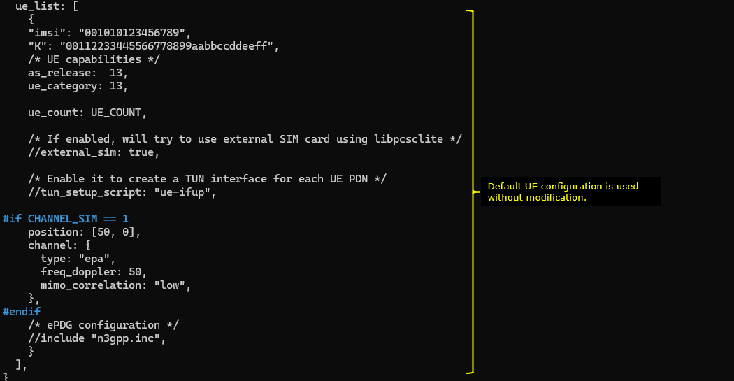
ue.default.cfg is configured as shown below. (
The key point here is that you don't need to configure any specific settings for satellite communication since Direct to Cell is designed to make Satellite communication possible with ordinary UE without any special modification. So in this tutorial, you will see all the configuration on UEsim remain same as in default configuration (ue.default.cfg)

Only band and channel (dl_earfcn) is changed to match eNB frequency and band settings.
ue_list configuration is also set to be same as in default.
Perform the Test
Run lte service on callbox and then check 'cell phy' and 'cell' command. Make it sure that cell is configured as you intended. In this test, band 7(FDD) is used

This is not the mandatory process.. but you may do this to collect SIB message in the log for a few seconds at the beginning. I did bcch=1 and after a few seconds did bcch=0.
![]()
Now start trace logging.
![]()
Power on UE on UEsim (If your DUT is a commercial phone, turn on the phone)
Wait until the DUT complete the initial attach. (
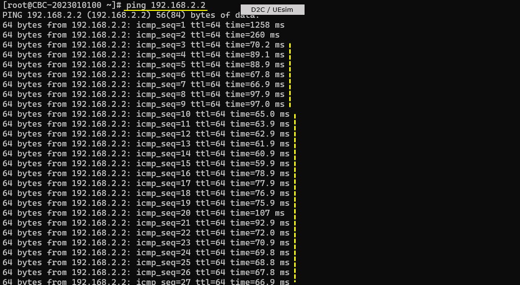
Try some data traffic (e.g, ping) to verify the data pipe setup. Check out the ttl time and see if it reflects the long propgation delay
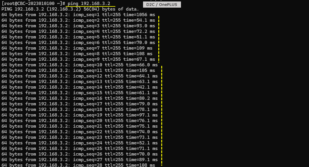

Log Analysis
Following is the log snapshot that are involved in communication with NTN.
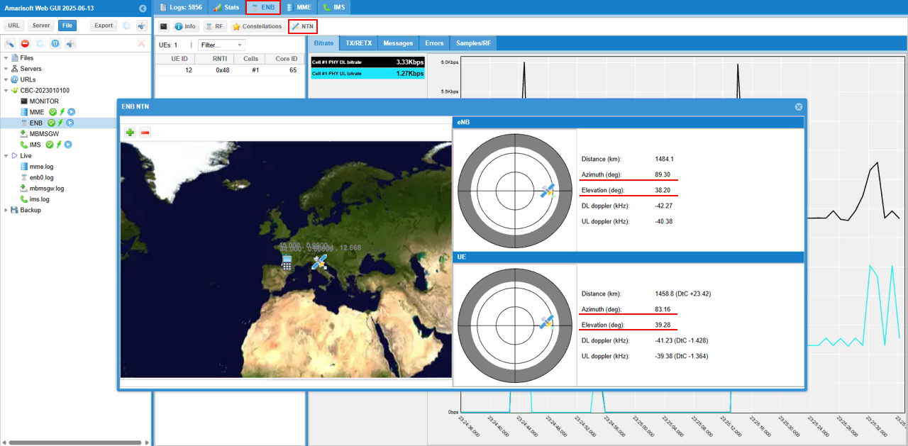
While the test is running, you can check out the position of eNB and UE in real time with WebGUI. While running, select [ENB] tab and hit [NTN] button and you see the view as shown below.
[eNB] pannel shows the sky view of eNB (sky view from eNB) and [UE] pannel shows the sky view of UE (sky view from UE). When the following value goes negative, satellite link gets disconnected since the satellite is not obserbable from UE.
- Elevation
- DtC value in Distance on UE pannel
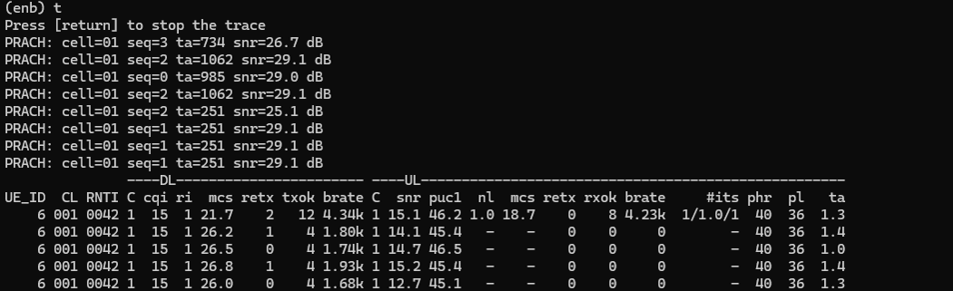
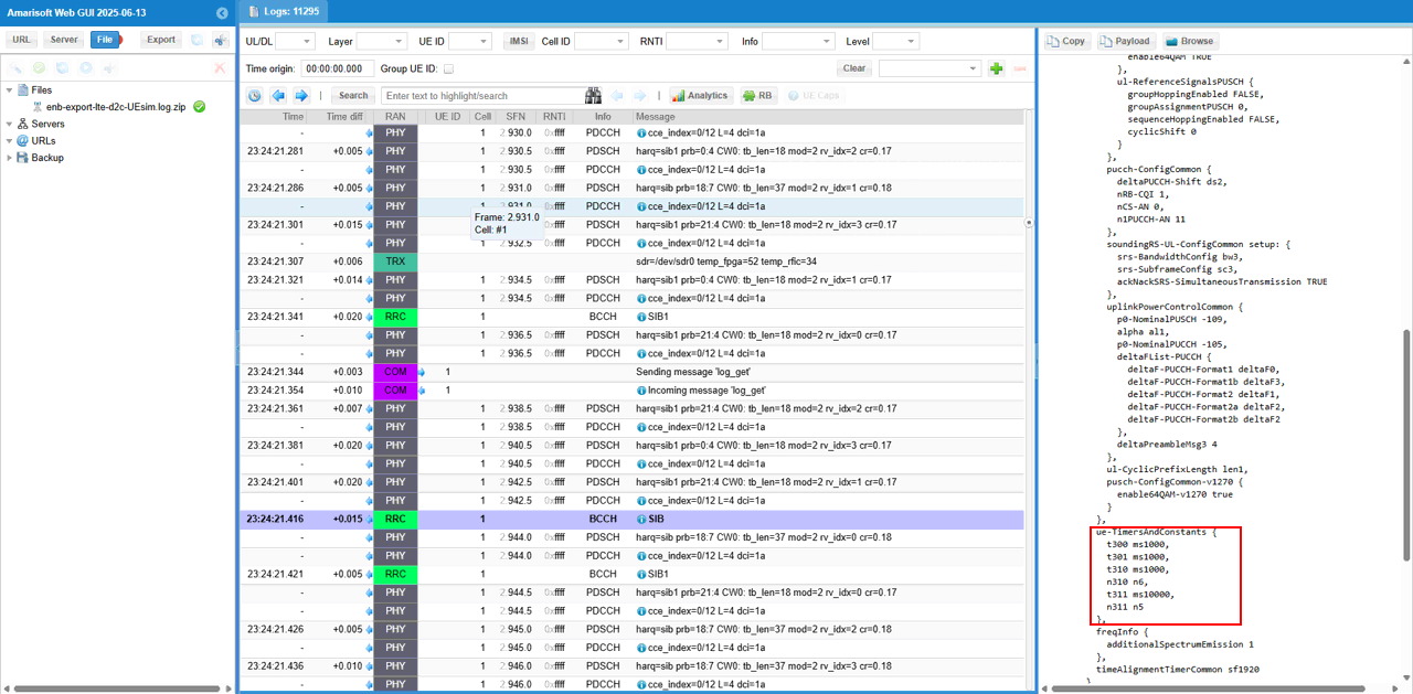
You may check out overall signaling sequence and details, in Direct to Cell there is almost no differences in signaling side from what you see regular communication (i.e, terrestrial communication). But there would be some tweakings of SIB parameters related to RACH configuration and timers to handle the long propation delay between the UE and Satellite.
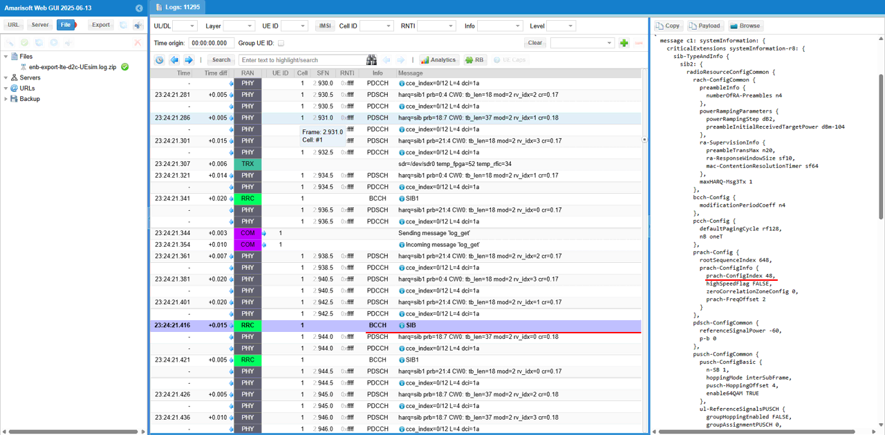
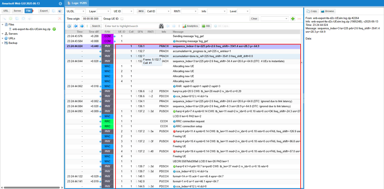
Then it would be good idea to check out the details on RACH. You would see 4 consetive RACH procedure going on here. This is a special modification on eNB to handle the large propagation delay during the RACH process. It is a kind of modification on the PRACH to be able to send the RAR to a future PRACH request : In LTE you cannot have less than 4 CBRA preamble so for one PRACH I send 4 RAR messages for each preamble
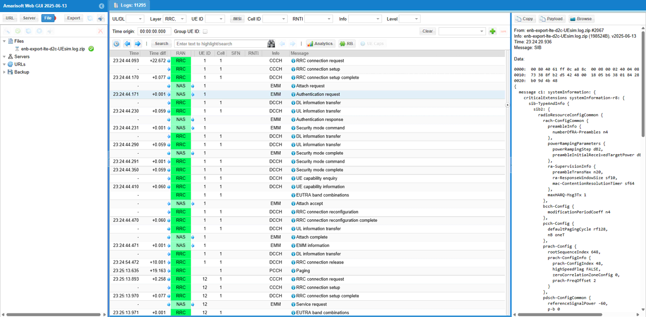
Now confirm that entire attach process gets completed
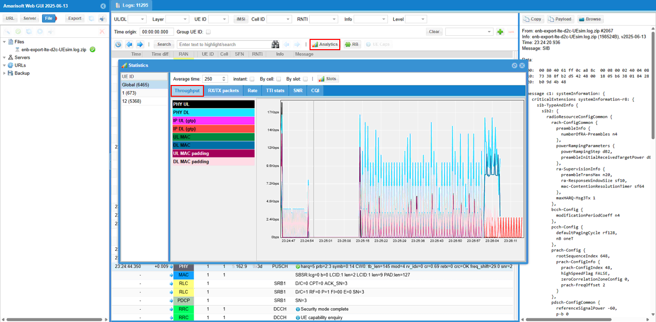
Check out throughput and see if you are getting expected throughput. In this test, I did continous ping to check if end to end data pipe is working OK.
Then check SNR to check the radio link quality over the course of the test. (NOTE : Connection between eNB and UEsim is via RF cable (i.e, conductive connection))
You can check out the signal quality percieved by UE from DL CQI plot
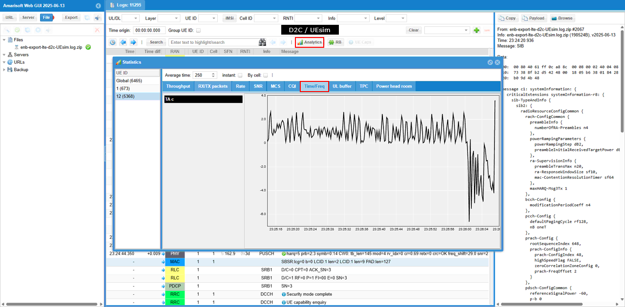
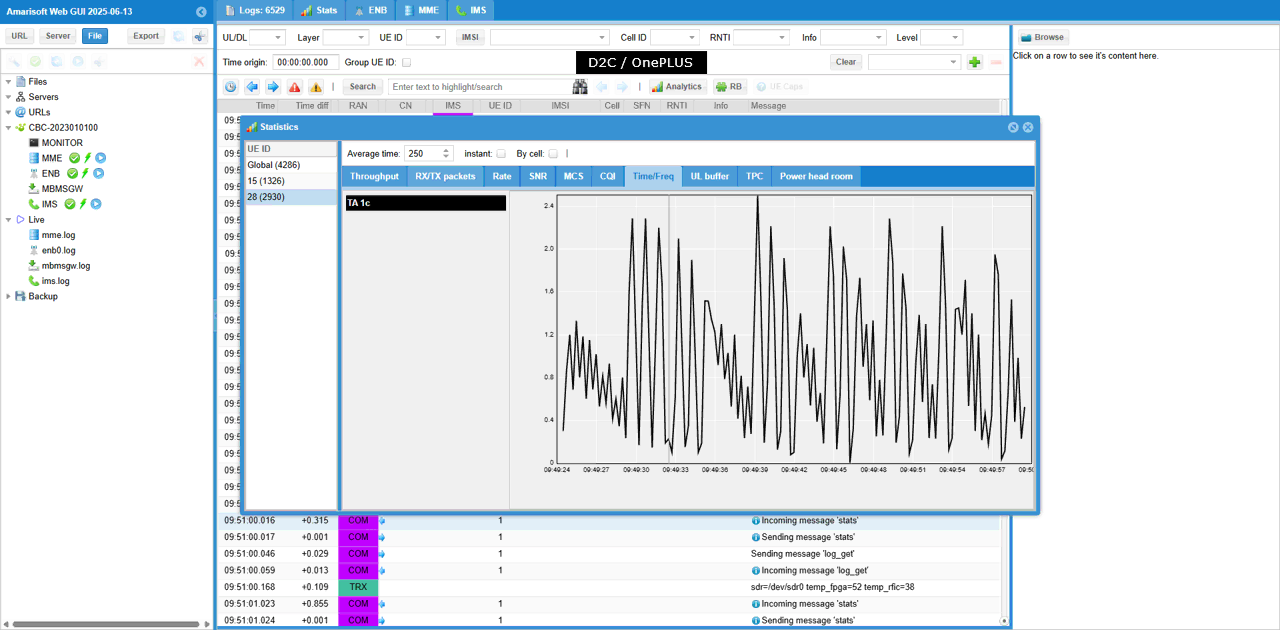
If you magnify TA command value in [Time/Freq] tab, you would see a pattern as shown below. ((NOTE : Connection between eNB and UEsim is via RF cable (i.e, conductive connection))