IoT LTE Cat - M1 UEsim
The purpose of this tutorial is to show you how to do basic connectivity test between a UEsim and Amari Callbox with LTE Cat-M1. The motivation of CatM1 is to implement a device that can achieve reliableconnection in low cost, low energy consumption. Followings are major technologies in Cat-M1 to achieve this goal.
- Reliable Connection : Repetitive transmission of Control and Data Channels
- Low Cost : Narrow Band, Low throughput requirement
- Low Energy Consumption : Long DRX
Table of Contents
Introduction
LTE Cat-M1, also known as LTE-M, is a pivotal cellular technology standard designed specifically for the fast-growing Internet of Things (IoT) ecosystem. Cat-M1 operates within the LTE network infrastructure and provides a tailored solution for low-power, low-cost devices that require reliable connectivity, such as smart meters, asset trackers, and wearable health monitors. Leveraging features such as reduced bandwidth (1.4 MHz), optimized signaling, and extended Discontinuous Reception (DRX) cycles, Cat-M1 enables devices to maintain extended battery life while supporting essential data transmission and mobile functionality. The Amari Callbox is a comprehensive LTE test platform that emulates network conditions and provides a controlled environment for evaluating the performance and interoperability of User Equipment simulators (UEsim) under Cat-M1 specifications. This tutorial guides you through the process of performing a basic connectivity test between a UEsim and an Amari Callbox, focusing on core Cat-M1 technologies that achieve reliability, cost-efficiency, and energy savings. Understanding and validating these connectivity mechanisms are crucial steps in the development and deployment of robust IoT solutions within the LTE landscape.
-
Context and Background
- LTE Cat-M1 Overview: A 3GPP standard designed for IoT devices, Cat-M1 provides a balance between cost, energy efficiency, and reliable connectivity, leveraging existing LTE networks with modifications for narrowband operation and power optimization.
- Amari Callbox: An LTE test system capable of simulating eNodeB and core network functionalities, allowing for comprehensive connectivity and performance testing in a controlled lab environment.
- UEsim: A User Equipment simulator that emulates LTE Cat-M1 device behavior, facilitating device-network interaction analysis without the need for physical hardware prototypes.
-
Relevance and Importance
- Validation of Cat-M1 Features: Ensures that IoT devices can reliably connect and operate within LTE networks while meeting stringent requirements for low power consumption and cost.
- Critical for IoT Deployments: Connectivity testing is essential for verifying device interoperability and network compliance, directly impacting device reliability in real-world applications.
-
Tutorial Objectives and Learning Outcomes
- Step-by-Step Connectivity Testing: Learn to configure and execute a basic Cat-M1 connectivity test between UEsim and Amari Callbox.
- Understanding Cat-M1 Technologies: Gain practical knowledge of repetitive transmission, narrowband operation, and DRX mechanisms for reliable, low-cost, and low-energy communication.
- Hands-On Skills: Develop the ability to analyze test results and troubleshoot common connectivity issues in Cat-M1 deployments.
-
Prerequisite Knowledge and Skills
- Basic Understanding of LTE Architecture: Familiarity with LTE network components, signaling, and device registration procedures is highly recommended.
- Experience with LTE Test Equipment: Prior exposure to tools like Amari Callbox and UEsim will be beneficial for following the tutorial effectively.
- Fundamental Networking Concepts: Knowledge of IP connectivity, wireless communication, and IoT device requirements will enhance comprehension.
Summary of the Tutorial
This tutorial outlines the step-by-step procedures for setting up and testing a Cat M1 UE simulator (UE sim) in conjunction with a call box (network simulator), with a focus on proper configuration, execution, and log analysis to validate the UE attach and registration process.
-
Test Setup and Configuration
- Ensure proper matching between UE sim configuration (ue-catm1.cfg) and Call box configuration (enb-catm1.cfg), using the provided configuration files without modification.
- If connecting to a different network or simulator, configure the UE sim to match the network's settings.
- Verify SIM information matches between UE sim and Call box.
-
Service Status Validation
- Check that the LTE service is running on the Call box by executing service lte status. If issues are detected, restart with service lte restart.
-
Screen Mode Operations
- Attach to screen sessions using screen -r for both UE sim and Call box consoles to facilitate simultaneous interaction.
- Familiarize with the command-line operations within screen mode for both UE sim and Call box as these will be used for most test procedures.
-
UE Attach Procedure
- Start tracing on the Call box to monitor the attach process.
- Power on the UE via UE sim and observe cell detection and SIB decoding messages.
- Once SIBs are decoded, monitor for successful initial attach on the Call box trace screen.
- Use cells command to verify cell registration and ue command on both (enb) and (mme) screens to check UE connectivity information.
-
Log Analysis
- Open /tmp/ue0.log on UE sim and /tmp/enb0.log on Call box for log review, using text editors such as nano.
- Analyze RRC and NAS signaling messages to confirm proper registration events and troubleshoot failures:
- SIB1 & SIB2: Examine for correct cell and radio resource configuration for Cat M1.
- Attach Request: Validate the UE's NAS capabilities and request parameters.
- RrcConnectionSetup: Confirm dedicated radio resource configuration for Cat M1 is sent by eNB.
- UE Capability Information: Verify the reported RRC capabilities of the UE.
- Attach Accept: Ensure network acceptance and activation of the default EPS bearer, including APN and PDN information.
- Use the log analysis to identify critical attach events and troubleshoot issues as needed. For detailed lower-layer analysis, the use of WebGUI is recommended.
In summary, the tutorial provides a comprehensive methodology for configuring, executing, and validating a Cat M1 UE attach procedure using a UE simulator and call box, with emphasis on configuration accuracy, service validation, hands-on test execution, and thorough log analysis for troubleshooting and verification purposes.
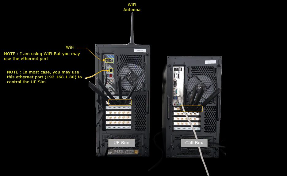
Test Setup
Test setup for this tutorial is as shown below.
Configuration
An important thing in using UE sim is to do proper matching between UE sim configuration and Call box configuration In this tutorial, I used the ue-catm1.cfg and and enb-catm1.cfg without any change
If you use other Network (e.g, other network simulator or real network), you have to make it sure to configure UE sim according to the settings on network side


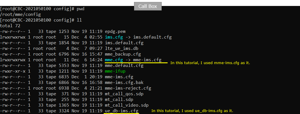
You would see following in /root/mme/config/ims-ims.cfg file on Callbox

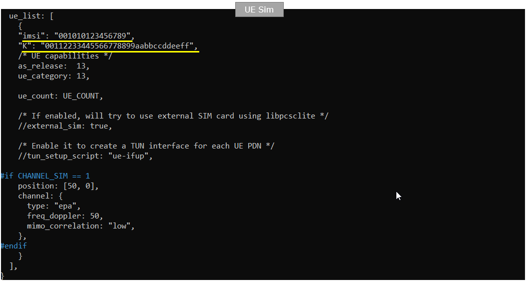
In this tutorial, following SIM information will be used. this is the configuration in ue-catm1.cfg on UEsim.
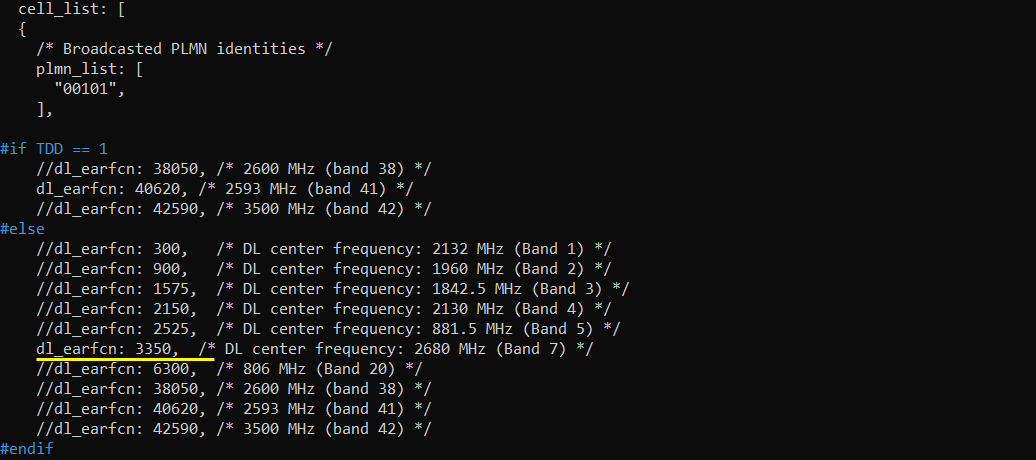
Following is the configuration on Callbox (enb-catm1.cfg)

Following is the configuration on UEsim (ue-catm1.cfg)

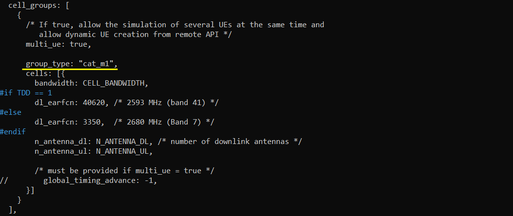
Check if LTE service is Running
Whatever you want to test, the first thing you need to do is that call box program (LTE Service) is running. You can check on the execution status of the call box program by running following command and you should get the result as shown below
# service lte status


NOTE : Getting this result is pre-requisite for Call Box Operation, but this result itself does not guarantee the normal operation. If you see some unexpected issues. You may restart the call box with following command
# service lte restart
Getting into Screen Mode
If it is confirmed that the lte service is running, go to screen mode by running 'screen -r' and follow through the steps as shown below. The steps shown here is the procedure that you would use for almost every test and it is highly recommended to get familiar with these steps. For further commands you can use in this screen mode, refer to the tutorial : Command Line Command
Run following command on UE sim

You will get the screen as shown below
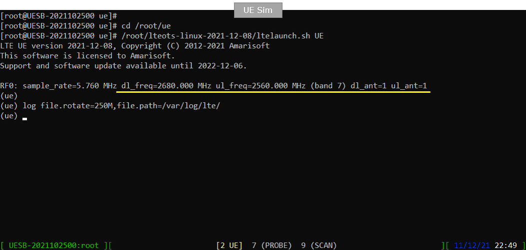
Run following command on Callbox

You will get the screen as shown below
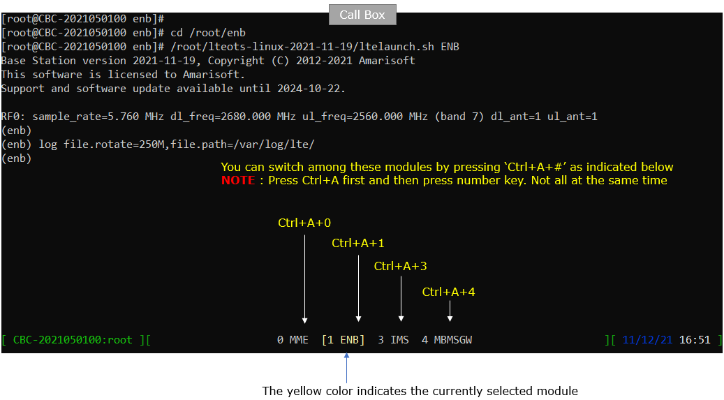
Attach UE
Now perform UE attach procedure. This would be a little bit busy process since you need to switch back and forth between Callbox screen and UEsim screen.
Start tracing on Callbox

power_on UE on UE sim.

You will see following message once UE detect the cell and decoded SIBs.

Once UE completed SIB decoding and perform initial attach, you will see following trace on Callbox screen.

When the initial attach completed, you can check on the cell information to which the UE sim is registered to with 'cells' command.

You can get the ue information that is in connection with gNB on Callbox with 'ue' command in (enb) screen.

You can get the ue information that is in connection with gNB on Callbox with 'ue' command in (mme) screen.

Log Analysis
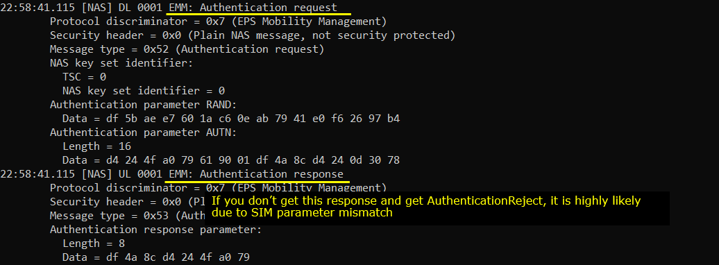
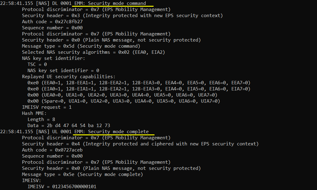
In this section, you will see how to confirm if UE registration is complete from trace log. You can use the same method to find any issues (e.g, registration failure) for troubleshooting. When UE registration fails, you may use this tutorial to figure out the point of the failure and troubleshoot
NOTE : This section is just to check quickly some important points in the log, but it may be a little bit tricky to do the detailed log analysis (especially for lower layer log analysis). In that case, I strongly recommend you to use WebGUI for the log analysis. You may refer to WebGUI Tutorial
Open /tmp/ue0.log on UEsim using any text editor. I am using nano in this tutorial. (NOTE : In the same way, you can check eNB log by opening /tmp/enb0.log on Callbox).
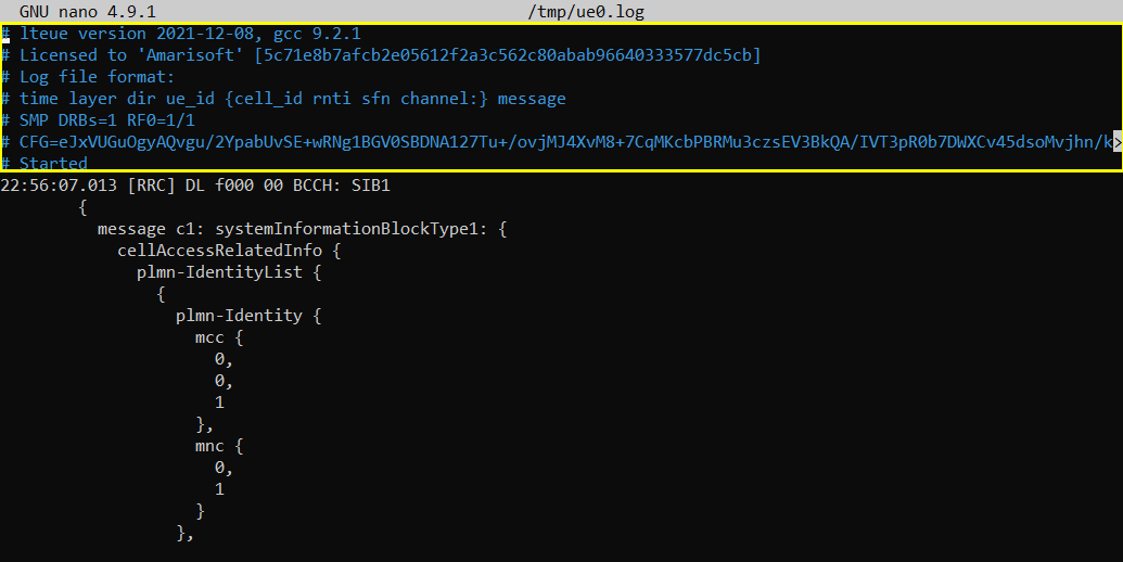


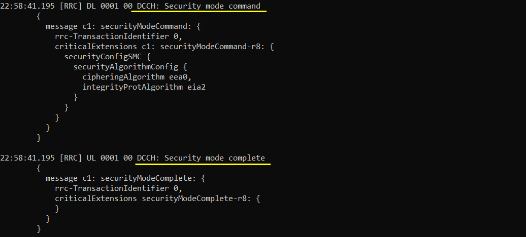
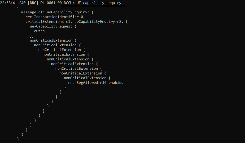
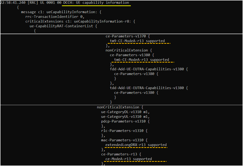


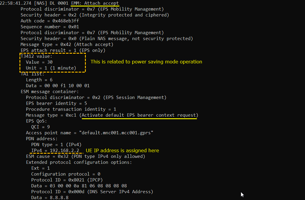

RRC / NAS Signaling
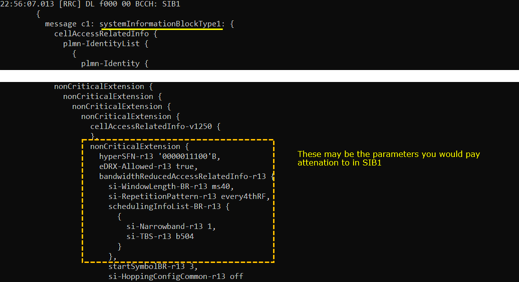
SIB1
: This is the SIB1 sent by eNB to configiture Cat M1 (
{
message c1: systemInformationBlockType1: {
cellAccessRelatedInfo {
plmn-IdentityList {
{
...
},
...
}
},
...
},
cellSelectionInfo {
...
},
p-Max 10,
freqBandIndicator 7,
schedulingInfoList {
...
},
si-WindowLength ms40,
systemInfoValueTag 0,
nonCriticalExtension {
nonCriticalExtension {
nonCriticalExtension {
nonCriticalExtension {
cellAccessRelatedInfo-v1250 {
},
nonCriticalExtension {
hyperSFN-r13 '0000001111'B,
eDRX-Allowed-r13 true,
bandwidthReducedAccessRelatedInfo-r13 {
si-WindowLength-BR-r13 ms40,
si-RepetitionPattern-r13 every4thRF,
schedulingInfoList-BR-r13 {
{
si-Narrowband-r13 1,
si-TBS-r13 b504
}
},
startSymbolBR-r13 3,
si-HoppingConfigCommon-r13 off
}
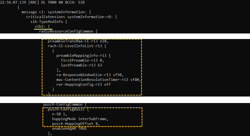
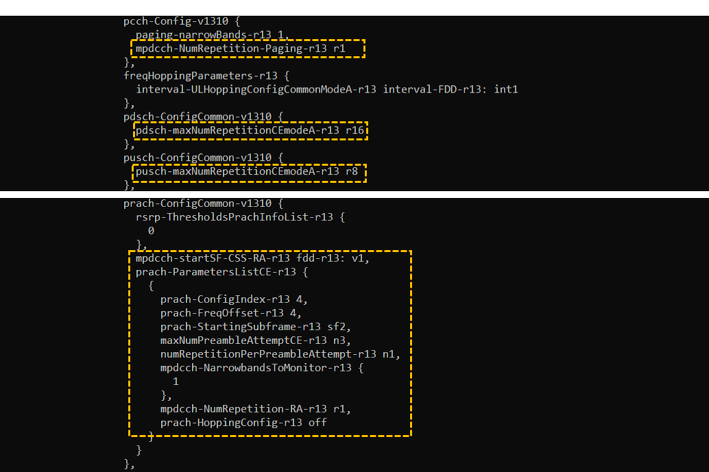
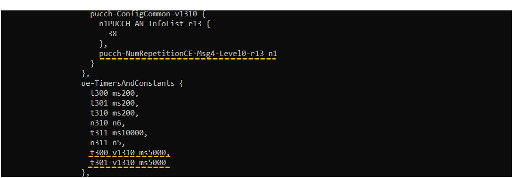
SIB2
: This is the SIB2 sent by eNB to configiture Cat M1 (
{
message c1: systemInformation: {
criticalExtensions systemInformation-r8: {
sib-TypeAndInfo {
sib2: {
radioResourceConfigCommon {
rach-ConfigCommon {
...
},
maxHARQ-Msg3Tx 5,
preambleTransMax-CE-r13 n10,
rach-CE-LevelInfoList-r13 {
{
preambleMappingInfo-r13 {
firstPreamble-r13 0,
lastPreamble-r13 63
},
ra-ResponseWindowSize-r13 sf50,
mac-ContentionResolutionTimer-r13 sf80,
rar-HoppingConfig-r13 off
}
}
},
bcch-Config {
...
},
pcch-Config {
...
},
prach-Config {
rootSequenceIndex 648,
prach-ConfigInfo {
prach-ConfigIndex 4,
highSpeedFlag FALSE,
zeroCorrelationZoneConfig 11,
prach-FreqOffset 4
}
},
pdsch-ConfigCommon {
...
},
pusch-ConfigCommon {
...
},
pucch-ConfigCommon {
...
},
soundingRS-UL-ConfigCommon setup: {
...
},
uplinkPowerControlCommon {
...
},
ul-CyclicPrefixLength len1,
pusch-ConfigCommon-v1270 {
enable64QAM-v1270 true
},
bcch-Config-v1310 {
modificationPeriodCoeff-v1310 n64
},
pcch-Config-v1310 {
paging-narrowBands-r13 1,
mpdcch-NumRepetition-Paging-r13 r1
},
freqHoppingParameters-r13 {
interval-ULHoppingConfigCommonModeA-r13 interval-FDD-r13: int1
},
pdsch-ConfigCommon-v1310 {
pdsch-maxNumRepetitionCEmodeA-r13 r16
},
pusch-ConfigCommon-v1310 {
pusch-maxNumRepetitionCEmodeA-r13 r8
},
prach-ConfigCommon-v1310 {
rsrp-ThresholdsPrachInfoList-r13 {
0
},
mpdcch-startSF-CSS-RA-r13 fdd-r13: v1,
prach-ParametersListCE-r13 {
{
prach-ConfigIndex-r13 4,
prach-FreqOffset-r13 4,
prach-StartingSubframe-r13 sf2,
maxNumPreambleAttemptCE-r13 n3,
numRepetitionPerPreambleAttempt-r13 n1,
mpdcch-NarrowbandsToMonitor-r13 {
1
},
mpdcch-NumRepetition-RA-r13 r1,
prach-HoppingConfig-r13 off
}
}
},
pucch-ConfigCommon-v1310 {
n1PUCCH-AN-InfoList-r13 {
38
},
pucch-NumRepetitionCE-Msg4-Level0-r13 n1
}
},
ue-TimersAndConstants {
t300 ms200,
t301 ms200,
t310 ms200,
n310 n6,
t311 ms10000,
n311 n5,
t300-v1310 ms5000,
t301-v1310 ms5000
},
freqInfo {
additionalSpectrumEmission 1
},
timeAlignmentTimerCommon infinity
},
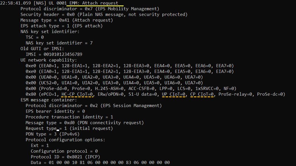
Attach Request
: This is the AttachRequest sent by UE to inform UE capability for IoT NAS feature (
Protocol discriminator = 0x7 (EPS Mobility Management)
Security header = 0x0 (Plain NAS message, not security protected)
Message type = 0x41 (Attach request)
EPS attach type = 1 (EPS attach)
NAS key set identifier:
TSC = 0
NAS key set identifier = 7
Old GUTI or IMSI:
IMSI = 001010123456789
UE network capability:
0xe0 (EEA0=1, 128-EEA1=1, 128-EEA2=1, 128-EEA3=0, EEA4=0, EEA5=0, EEA6=0, EEA7=0)
0xe0 (EIA0=1, 128-EIA1=1, 128-EIA2=1, 128-EIA3=0, EIA4=0, EIA5=0, EIA6=0, EIA7=0)
0x00 (UEA0=0, UEA1=0, UEA2=0, UEA3=0, UEA4=0, UEA5=0, UEA6=0, UEA7=0)
0x00 (UCS2=0, UIA1=0, UIA2=0, UIA3=0, UIA4=0, UIA5=0, UIA6=0, UIA7=0)
0x00 (ProSe-dd=0, ProSe=0, H.245-ASH=0, ACC-CSFB=0, LPP=0, LCS=0, 1xSRVCC=0, NF=0)
0x80 (ePCO=1, HC-CP CIoT=0, ERw/oPDN=0, S1-U data=0, UP CIoT=0, CP CIoT=0, ProSe-relay=0, ProSe-dc=0)
ESM message container:
Protocol discriminator = 0x2 (EPS Session Management)
EPS bearer identity = 0
Procedure transaction identity = 1
Message type = 0xd0 (PDN connectivity request)
Request type = 1 (initial request)
PDN type = 3 (IPv4v6)
Protocol configuration options:
Ext = 1
Configuration protocol = 0
Protocol ID = 0x8021 (IPCP)
Data = 01 00 00 10 81 06 00 00 00 00 83 06 00 00 00 00
Protocol ID = 0x0001 (P-CSCF IPv6 Address Request)
Data =
Protocol ID = 0x0003 (DNS Server IPv6 Address Request)
Data =
Protocol ID = 0x000a (IP address allocation via NAS signalling)
Data =
Protocol ID = 0x000c (P-CSCF IPv4 Address Request)
Data =
Protocol ID = 0x000d (DNS Server IPv4 Address Request)
Data =
Voice domain preference and UE's usage setting = 0x05 (IMS PS Voice only, Data centric)
MS network feature support = 0x01 (MS supports the extended periodic timer in this domain)
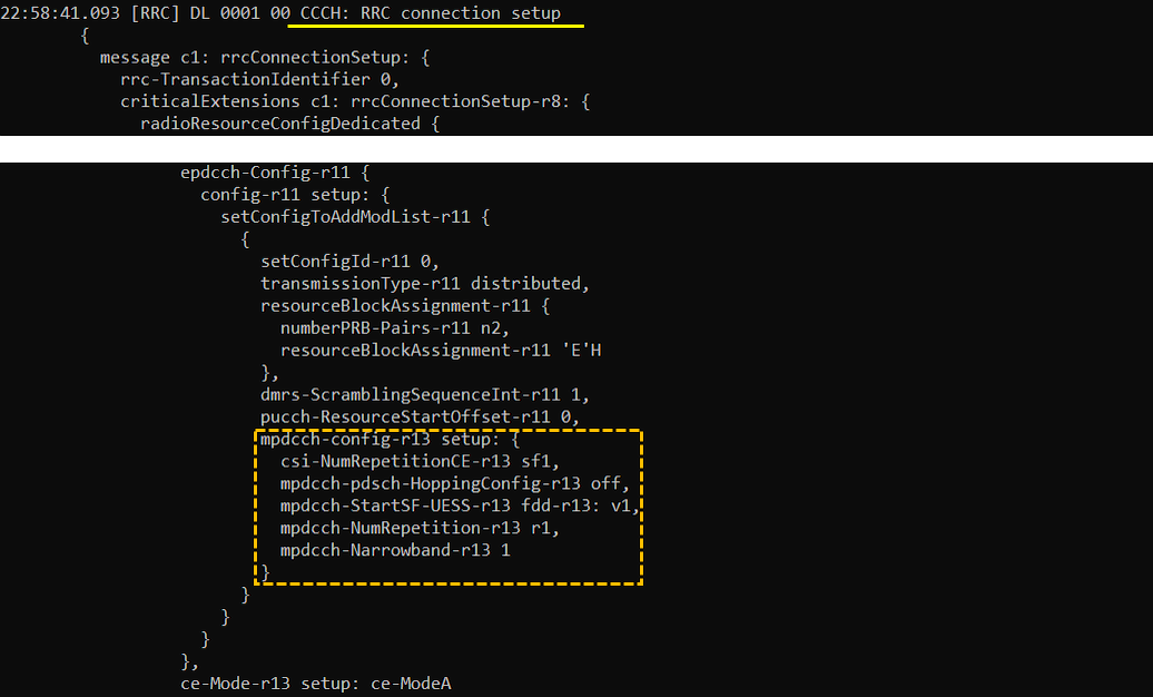
RrcConnectionSetup
: This is the RrcConnectionSetup sent by eNB to configiture Cat M1 (
{
message c1: rrcConnectionSetup: {
rrc-TransactionIdentifier 0,
criticalExtensions c1: rrcConnectionSetup-r8: {
radioResourceConfigDedicated {
srb-ToAddModList {
...
},
mac-MainConfig explicitValue: {
...
},
physicalConfigDedicated {
...
},
soundingRS-UL-ConfigDedicated release: NULL,
schedulingRequestConfig setup: {
...
},
epdcch-Config-r11 {
config-r11 setup: {
setConfigToAddModList-r11 {
{
setConfigId-r11 0,
transmissionType-r11 distributed,
resourceBlockAssignment-r11 {
numberPRB-Pairs-r11 n2,
resourceBlockAssignment-r11 'E'H
},
dmrs-ScramblingSequenceInt-r11 1,
pucch-ResourceStartOffset-r11 0,
mpdcch-config-r13 setup: {
csi-NumRepetitionCE-r13 sf1,
mpdcch-pdsch-HoppingConfig-r13 off,
mpdcch-StartSF-UESS-r13 fdd-r13: v1,
mpdcch-NumRepetition-r13 r1,
mpdcch-Narrowband-r13 1
}
}
}
}
},
ce-Mode-r13 setup: ce-ModeA
}
UE Capability Information
: This is the UE Capability Information sent by UE to inform RRC capability for Cat M1 (
{
message c1: ueCapabilityInformation: {
rrc-TransactionIdentifier 0,
criticalExtensions c1: ueCapabilityInformation-r8: {
ue-CapabilityRAT-ContainerList {
{
rat-Type eutra,
ueCapabilityRAT-Container {
accessStratumRelease rel13,
ue-Category 1,
pdcp-Parameters {
...
}
},
phyLayerParameters {
...
},
rf-Parameters {
...
},
measParameters {
bandListEUTRA {
...
}
},
featureGroupIndicators '4E001002'H /*
2: PUCCH 2a/2b, abs TPC, RB alloc type 1 for PDSCH, Periodic CQI/PMI/RI reporting on PUCCH: Modes 2-0 and 2-1
5: Long DRX cycle, DRX Mac CE
6: Prioritized bit rate
7: RLC UM
20: SRB1 and SRB2 for DCCH + 8x DRB
31: MFBI
*/,
interRAT-Parameters {
},
nonCriticalExtension {
phyLayerParameters-v920 {
},
interRAT-ParametersGERAN-v920 {
},
csg-ProximityIndicationParameters-r9 {
},
neighCellSI-AcquisitionParameters-r9 {
},
son-Parameters-r9 {
},
nonCriticalExtension {
lateNonCriticalExtension {
nonCriticalExtension {
nonCriticalExtension {
nonCriticalExtension {
nonCriticalExtension {
nonCriticalExtension {
nonCriticalExtension {
nonCriticalExtension {
nonCriticalExtension {
nonCriticalExtension {
nonCriticalExtension {
nonCriticalExtension {
nonCriticalExtension {
ce-Parameters-v1370 {
tm9-CE-ModeA-r13 supported
},
nonCriticalExtension {
ce-Parameters-v1380 {
tm6-CE-ModeA-r13 supported
},
fdd-Add-UE-EUTRA-Capabilities-v1380 {
ce-Parameters-v1380 {
}
},
tdd-Add-UE-EUTRA-Capabilities-v1380 {
ce-Parameters-v1380 {
}
...
},
nonCriticalExtension {
nonCriticalExtension {
nonCriticalExtension {
nonCriticalExtension {
pdcp-Parameters-v1130 {
},
phyLayerParameters-v1130 {
tdd-SpecialSubframe-r11 supported
},
rf-Parameters-v1130 {
},
measParameters-v1130 {
},
interRAT-ParametersCDMA2000-v1130 {
},
otherParameters-r11 {
},
nonCriticalExtension {
nonCriticalExtension {
rf-Parameters-v1180 {
freqBandRetrieval-r11 supported
},
nonCriticalExtension {
nonCriticalExtension {
nonCriticalExtension {
nonCriticalExtension {
nonCriticalExtension {
nonCriticalExtension {
ue-CategoryDL-v1310 m1,
ue-CategoryUL-v1310 m1,
pdcp-Parameters-v1310 {
},
rlc-Parameters-v1310 {
},
mac-Parameters-v1310 {
extendedLongDRX-r13 supported
},
ce-Parameters-r13 {
ce-ModeA-r13 supported
},
interRAT-ParametersWLAN-r13 {
},
wlan-IW-Parameters-v1310 {
},
lwip-Parameters-r13 {
}
....
},
nonCriticalExtension {
nonCriticalExtension {
ue-RadioPagingInfo-r12 {
ue-CategoryDL-v1310 m1,
ce-ModeA-r13 true
}
Attach Accept
: This is the AttachAccept sent by UE to inform NW capability for IoT NAS feature and Activate Default EPS Bearer(
Protocol discriminator = 0x7 (EPS Mobility Management)
Security header = 0x2 (Integrity protected and ciphered)
Auth code = 0x63483d18
Sequence number = 0x01
Protocol discriminator = 0x7 (EPS Mobility Management)
Security header = 0x0 (Plain NAS message, not security protected)
Message type = 0x42 (Attach accept)
EPS attach result = 1 (EPS only)
T3412 value:
Value = 30
Unit = 1 (1 minute)
TAI list:
Length = 6
Data = 00 00 f1 10 00 01
ESM message container:
Protocol discriminator = 0x2 (EPS Session Management)
EPS bearer identity = 5
Procedure transaction identity = 1
Message type = 0xc1 (Activate default EPS bearer context request)
EPS QoS:
QCI = 9
Access point name = "default.mnc001.mcc001.gprs"
PDN address:
PDN type = 1 (IPv4)
IPv4 = 192.168.2.2
ESM cause = 0x32 (PDN type IPv4 only allowed)
Extended protocol configuration options:
Ext = 1
Configuration protocol = 0
Protocol ID = 0x8021 (IPCP)
Data = 03 00 00 0a 81 06 08 08 08 08
Protocol ID = 0x000d (DNS Server IPv4 Address)
Data = 8.8.8.8
GUTI:
MCC = 001
MNC = 01
MME Group ID = 32769
MME Code = 1
M-TMSI = 0x275be002
Emergency number list:
Length = 8
Data = 03 1f 19 f1 03 1f 11 f2
EPS network feature support:
0x01 (CP CIoT=0, ERw/oPDN=0, ESRPS=0, CS-LCS=0, EPC-LCS=0, EMC BS=0, IMS VoPS=1)
0x08 (15 bearers=0, IWK N26=0, RestrictDCNR=0, RestrictEC=0, ePCO=1, HC-CP CIoT=0, S1-U data=0, UP CIoT=0)