PCI Express CPRI Board version 2026-03-18*This document is based on the latest test release.
Features may not be present in your current installed software. You may check their availability in change history or in your release documentation.
If you require an up to date release, ask for it in a ticket.
Features may not be present in your current installed software. You may check their availability in change history or in your release documentation.
If you require an up to date release, ask for it in a ticket.
Table of Contents
1 Features
- CPRI line bit rate option 3,4,5 and 7 (bandwidth are 4, 5, 8 and 16 multiple of 614.4 Mbps)
- Suitable for up to four 2T2R (or two 4T4R) 20 MHz LTE cells
- Support for one 4T4R 100MHz NR(5G) cell with optionnal proprietary IQ compression
- Support input sample rate of 3.84, 7.68, 15.36, 23.04, 30.72, or 122.88 Msp/s
- 15 bits sample width
- Fast C&M support via Ethernet TUN interface
- Easy-to-add vendor specific information in CPRI control word
- Full support of mapping method 1 (contiguous)
- Support of mapping method 3 (interleaved) for a single cell only
Some hardware constraints apply:
- The two top SFP connector (port 0 and port 1) can support all line bit rates.
- The two bottom ports (port 2 and port 3) are limited to line rate 5 (mult 8)
- All SFP ports must use the same line bit rate
- Total combined bandwidth cannot exceed 10Gb/s
Possible combinations examples are:
- line rate 7 (mult 16) on port 0 for 4T4R 100MHz NR with compression
- line rate 5 (mult 8) on ports 0 and 1 for 2x 4T4R 20MHz LTE
- line rate 3 (mult 4) on ports 0, 1, 2 and 3
2 Installation with the Amarisoft software
2.1 Introduction
Amarisoft PCIe CPRI board uses the same driver as the Amarisoft PCIe SDR board. So you don’t need to install anything if you already have a setup running with the SDR boards. Note that you can have SDR and CPRI boards plugged in the same PC. Board type is recognized automatically by the driver.
If you have bought the OTS (Off-The-Shelve) package, then you don’t need to install anything. Everything has already been installed on your PC. Otherwise, please follow through the steps below.
Decompress the trx_sdr archive into a convenient directory specified by <trx_path>.
tar -xzf trx_sdr-linux-YYYY-MM-DD.tar.gz -C <trx_path>
You have two ways to install the TRX driver for the PCIe card:
- automatic
- manual
For both cases, the installation requires some specific packages to compile the kernel module. To do this, you need to be root. In Fedora and Cent OS, you need to install kernel-devel, make, gcc and elfutils-libelf-devel packages by running the following command:
dnf install kernel-devel-$(uname -r) make gcc elfutils-libelf-devel
For Ubuntu, use the following command:
apt-get install $(uname -a | awk '{print $3}') build-essential
Note that you’ll need equivalent packages for other Linux distributions if you do not use Fedora, Ubuntu or Cent OS.
Once you have finished the installation, you need to initialize (See Driver initialization) and upgrade your driver (See Firmware upgrade). Please make sure to initialize the driver after each system boot if you have not activates an automatic lte service.
2.2 Automatic Installation
Automatic installation is only available on Fedora, Ubuntu and CentOS distributions. Use manual install for other distributions. To start your automatic install, use the following command where <path> is the path to the directory where you have already installed your LTE component (eNB or UE) and type should be set to enb or ue accordingly.
./install <path> <type>
Notes:
- the script would install some packages, so make sure you have root privileges when you run the script
- this install creates a symlink for the TRX driver so please do not remove this directory afterwards.
2.3 Manual Installation
To manually install the driver, let’s note <path> the directory where Amarisoft eNB or UE software is installed. Then:
- Compile kernel driver:
Go to the kernel/ directory under <trx_path> and start compilation:cd kernel make
- Place driver:
Just copy the compiled driver into <path> directorycd .. cp trx_sdr.so <path> cp libsdr.so <path>
- Config files:
Copy RF driver config file. Note that there are 2 separate config directories for eNB and UE called config.enb and config.ue under your <trx_path>. As a result, the <config_dir> should be set to config.enb or config.ue accordingly.cp -r <config_dir> <path>/config/sdr
Select frontend:
<path>/config/rf_select.sh sdr
2.4 Driver initialization
Each time you boot your system, you need to perform this initialization. Note that if you are using OTS install, this step is already done by the lte service.
cd kernel
./init.sh
2.5 Firmware upgrade
Perform the following command to upgrade your PCIe card:
./sdr_util upgrade
Notes:
- If you have several PCIe cards installed, this will upgrade all cards.
- If the firmware is already up to date, this command will end directly.
- When the upgrade is over, you need your system to be powered off for the changes to take effect (not only reset, real power off).
2.6 Multiple card installation
Several CPRI boards can be installed on a same PC and functions independently
When you install several CPRI cards, the mapping between the PCI connectors and the Linux devices is not predictable (but it shouldn’t change after each boot). To identify the order please do the following:
./sdr_util -c 0 led 1
Then check inside PC on each board, one of them should have a led blinking. This is card 0 (/dev/sdr0).
Switch off the led:
./sdr_util -c 0 led 0
You can do the same for other cards:
./sdr_util -c <n> led 1
Where <n> is the index of the card.
3 TRX driver configuration options
3.1 Single card configuration
The following properties are available:
namerf_driver.nameString. Set the driver to use, always set "sdr" to use Amarisoft driver.
argsrf_driver.argsString. Set the system device names for the boards. Example:
args: "dev0=/dev/sdr0"
args: "dev0=/dev/sdr0,dev1=/dev/sdr2"
syncrf_driver.syncOptional enumeration: none, gps, external, cpri (default = none). Set the time synchronization source.
noneuses the internal PPS generated from the clock.gpsuses the GPS synchronization when a GPS antenna is connected to the GPS port.externaluses the PPS from the CLK IN connector (CN7 on Figure 8.1).cprisynchronizes itself with the CPRI frame received in the SFP port, to be used when the board behaves in ’slave’ or RE mode.When several cards are selected (with the
argsproperty),synconly sets the time synchronization source of the first card. The other cards are implicitly set toexternalsynchronization, assuming the previous card is used as source.clockrf_driver.clockOptional enumeration: internal, external (default = internal). Set the clock source.
internaluses the internal clock (VCTCXO). If an external PPS sync source is used, the internal clock frequency is adjusted by the PPS signal.externaluses the clock from the CLK IN connector (CN7 on Figure 8.1).cpri_multrf_driver.cpri_multInteger. Select the CPRI line bit rate in terms of multiple of option 1 (614.4 Mbps). E.g set 4 for option 3, 8 for option 5 and 16 for option 7.
Use comma separated list for multiple card configuration (Multiple card configuration).cpri_multandcpri_optionare mutually exclusive.
cpri_optionrf_driver.cpri_optionString or integer. Select the CPRI line bit rate based on CPRI option.
Use comma separated list for multiple card configuration (Multiple card configuration).cpri_multandcpri_optionare mutually exclusive.
cpri_mappingrf_driver.cpri_mappingOptional enumeration: standard, hw, spread (default = standard) Selects the mapping method. (Sample mode, 15 bits per I or Q).
standardis mapping method 1 (all AxC are contiguous).hwis method 1 with offloads onto the board hardware.spreadis mapping method 3 (AxC are interleaved). Note that spread mapping is only partially supported.
Use comma separated list for multiple card configuration (Multiple card configuration).fast_cm_pointerrf_driver.fast_cm_pointerOptional integer (default = 54). Range 20-63. Value of the ’p’ pointer (control word #194) defining the start subchannel of the fast C&M channel which will span subchannels p to 63.
Use comma separated list for multiple card configuration (Multiple card configuration).ifnamerf_driver.ifnameString. Interface name of the TUN interface connected to the fast C&M channel.
Use comma separated list for multiple card configuration (Multiple card configuration).vss_datarf_driver.vss_dataOptional string to configure vendor specific data in the CPRI control word Format is string of pipe | separated items of the form X:data where X is the control word index X = Ns + 64*Xs and data is a hex string of length equals to the CPRI line multiplier. The first byte in the string corresponds to byte 0 in the CPRI frame, the second byte to byte 1, etc. If data is smaller than the CPRI multiplier, it will be right-padded with 0. Example for a CPRI multiplier of 16 (option 7, 9830.4 Mbps) to write a full data at index 16 and a single byte at index 80 :
vss_data : "16:0123456789ABCDEF0123456789ABCDEF|80:FF". Note that any vendor specific data overlapping with the fast C&M channel will be overwritten by the Ethernet data.
Use comma separated list for multiple card configuration (Multiple card configuration).cpri_rx_delayrf_driver.cpri_rx_delayOptional floating point value in microseconds (default 0).
Delay between TX and RX position in CPRI frame. This should be set to the value of (T2a + T3a - Toffset) provided by the RRH specification.
Check Delay management for more details.
Use comma separated list for multiple card configuration (Multiple card configuration).cpri_tx_delayrf_driver.cpri_tx_delayOptional floating point value in microseconds (default 0).
Advance Start of Frame relative to PPS to compensate for delays in transmit line and RRH. This should be set to T12 + T2a.
Check Delay management for more details.
Use comma separated list for multiple card configuration (Multiple card configuration).cpri_tx_dbmrf_driver.cpri_tx_dbmOptional floating point value in dBm (default 0). Needed by ENB/GNB to have a notion of actual output power. Computed from maximum power output of the RRH for a 0dBFS input signal (full scale). You need to take into account the loss in RF cables and efficiency of antennas. Exemple: RRH spec is 5Watt for -14dBFS input, so: +37dBm for -14dBFS: tx_gain = +51dB gain. In this case, parameter
cpri_tx_dbmcould be set to 51.0, but actual value for best performance was 42.0.
Use comma separated list for multiple card configuration (Multiple card configuration).cpri_rx_dbmrf_driver.cpri_rx_dbmOptional floating point value in dBm (default 0). Needed by ENB/GNB to have a notion of actual received power. Computed from analog input power of the RRH for a 0dBFS digital level (full scale). You need to take into account the loss in RF cables and efficiency of antennas. Exemple: RRH spec is -40dBm for 0dBFS input, so: rx_gain = +40dB gain. In this case, parameter
cpri_rx_dbmcould be set to 40.0, but actual value for best performance maybe slightly lower.
Use comma separated list for multiple card configuration (Multiple card configuration).tx_subch_dump_filerf_driver.tx_subch_dump_fileOptional string. If present, the control words of the sent CPRI hyperframes are dumped to the file specified by the parameter, in binary format. The control word of each hyperframe consists in 256 words of
cpri_multbytes. The words of the control channel are dumped by increasing number of subchannels, i.e with the index in the following order 0, 64, 128, 192, 1, 65, ... To spare CPU resources, only one every 16 hyperframes is dumped to the file. The file begins with a four bytes header : 0x43 0x50 0x90 <cpri_mult>. Due to the rapidly increasing file size, it is strongly recommended to use this parameter only for a short duration and for debug purposes.
Use comma separated list for multiple card configuration (Multiple card configuration).rx_subch_dump_filerf_driver.rx_subch_dump_fileOptional string. If present, the control words of the received CPRI hyperframes are dumped to the file specified by the parameter. The file has the same structure than
tx_subch_dump_file
Use comma separated list for multiple card configuration (Multiple card configuration).eth_preamble_sizerf_driver.eth_preamble_sizeOptional integer (default 7). Number of bytes of the Ethernet preamble for Fast C&M channel. Minimum size is 2 (preamble is then 0x55 0xd5). Maximum size is 7 (0x55 0x55 0x55 0x55 0x55 0x55 0xd5).
Use comma separated list for multiple card configuration (Multiple card configuration).cpri_hookrf_driver.cpri_hookOptional string. If set defines the CPRI hook shared library to use (cf api/cpri_hook.c for example).
Use comma separated list for multiple card configuration (Multiple card configuration).cpri_hook_datarf_driver.cpri_hook_dataOptional string. If set, will be passed to CPRI hooks as user data.
Use comma separated list for multiple card configuration (Multiple card configuration).cpri_debugrf_driver.cpri_debugOptional integer (default = 0). It positive, debug information will be diplayed in terminal
cpri_sample_offsetrf_driver.cpri_sample_offsetOptional string. List of integers separated by
:. Each integer defines the position in bits of channel IQ samples inside basic frames.dev_ref_portsrf_driver.dev_ref_portsOptional integer (default = 1). Defines how many TRX RF ports to map to this device.
You may usecpri_sample_offsetto manually set IQ samples position within CPRI hyperframe.rx_chan_mappingrf_driver.rx_chan_mappingOptional string. By default, if radio frontend has more RX channel available than configured (Ex: more physical RX connctor on SDR or more channel in CPRI hyperframes), drvers uses the first channels of the radio frontend.
This parameter allows to select the RX channels of the radio frontend to use.
This parameter is a list of number (Must have as many number as RF port configuration) separated by colons. Each number represents the RX channel of the radio frontend to use.
3.2 Multiple card configuration
All single card configuration parameters apply to multiple card mode.
To differentiate configuration for each card, the syntax of some parameter will change
to a list of value separated by commas (,).*
The first value will apply to the first board defined in args argument, ...
Example:
cpri_mult: "4,16"
Will mean dev0 will use CPRI speed 4 and dev1 will use CPRI speed 16
This syntax applies to the following parameters:
- cpri_mult
- cpri_option
- cpri_mapping
- fast_cm_pointer
- cpri_sample_offset
- vss_data
- cpri_debug
- cpri_tx_delay
- cpri_rx_delay
- cpri_tx_dbm
- cpri_rx_dbm
- tx_subch_dump_file
- rx_subch_dump_file
- eth_preamble_size
- ifname
- cpri_hook
- cpri_hook_data
- rx_chan_mapping
4 Time
4.1 Delay management
To configure delays and adjust propagation delays to that TX signal is aligned to PPS and RX is aligned to TX, you need to setup cpri_tx_delay and cpri_rx_delay.
cpri_tx_delay is used to align TX signal to PPS.
The CPRI driver uses this value to start sending of hyperframes before its own PPS so that the associated
signal reaches antenna at the correct time.
This delay should be set to T12 + T2a
cpri_rx_delay is used to align TX and RX signal and ensure synchronization for TDD.
The CPRI driver use this value to apply an offset to the received signal inside the hyperframes
to compensate propagation delay and align RX to TX.
When the CPRI driver receives an hyperframe, it uses its HFN/BFN to compute the timestamp of the signal
and removes the cpri_rx_delay.
This delay should be set to T2a + T3a - Toffset
Example:
The BBU generates the signal to t=0 (Ex: start of a frame).
The signal is put in HFR:0.0 (HFN=0, BFN=0) and is sent to RRU at t=-(T12 + T2a)

HFR:0.0 reaches R2 at t=-T2a
HFR:0.0 reaches antenna at t=0 as expected

The RRU generates HFR:0.0 at t=-T2a + Toffset as it aligns on received
HFR:0.0 at t=-T2a.
The signal put in HFR:0.0 is the one received -T3a earlier at antenna side.
Which means that HFR:0.0 sent by RRU is filled with signal received at
antenna side at t=-T2a + Toffset - T3a.
4.2 GPS usage
You can check the GPS operation when the eNodeB/UE is stopped with
./sdr_util gps_state
The GPS takes a few minutes to lock if the GPS antenna is
connected. Any active GPS antenna accepting a 3.3V DC supply can be
used, for example: http://www.mouser.fr/Search/ProductDetail.aspx?R=ANT-GPS-SH-SMAvirtualkey59000000virtualkey712-ANT-GPS-SH-SMA
To ensure the PLL is correctly locked when launching the lte software, it is recommended to set the synchro to GPS beforehand with the command
./sdr_util sync_gps
4.3 Oscillator frequency fine tuning
If you don’t have a GPS, it is still possible to manually fine tune the VCTCXO (Voltage Controlled, Temperature Controlled Crystal Oscillator) frequency provided you have a way to know the offset:
./sdr_util clock_tune n
where n is the offset in PPM (parts-per-million) from the nominal TCXO frequency. Note: the PPM offset n to voltage law is only approximative, so you should adjust it by successive approximation.
5 CPRI in practice
We recommend to take a look at this tutorial to learn more about CPRI.
We also recommend to set cpri_debug to 1 in your configuration file. It will give you useful information about cpri mapping.
Ex:
### CPRI initialization ###
  Speed:            x4
  Channels:         2
  Bits per samples: 30
  Hardware mapping: on
  Ethernet:
    Speed:          10
    Buffer size:    131072
    Preamble size:  7
  RF port 0:
    Channels:       2
    Offset bits:    360 420
    Samples/chan:   2 (120 bits)
    Use HW mapping
  Mapping:
    Channel 0.0:  360 =>  420
    Channel 0.1:  420 =>  480
    120/480 bites used
6 Miscellaneous utilities
6.1 sdr_util
usage: sdr_util [options] cmd [args...]

Options:
-h                         help
-c device_num              select the device (default = all)

Available commands:
version                    dump the FPGA version
sync_state                 dump the synchro and clock state
gps_state                  dump the GPS state
sync_gps                   select GPS as sync source, wait for stable state
gps_cal [-s]               uses the GPS sync to tune VCXO, optionnaly stores the value in flash
temp                       dump the temperature of the board components
led [0|1]                  enable/disable led blinking
clock_tune n               tune TCXO frequency offset to n ppm
upgrade [options]          upgrade the FPGA firmware
  upgrade options are:
  -force                   force upgrade even if identical or
                           previous version
7 C API
The PCIe CPRI board can be used in other projects with its C API. The C
API allows to send and receive I/Q samples and to change the various
parameters (frequency, sample rate, bandwidth, gains, ...). The
Amarisoft TRX driver, sdr_play and sdr_spectrum are
built using this API.
The C API is described in libsdr.h. The corresponding Linux x86_64 dynamic library is libsdr.so.
Amarisoft does not provide any support for this API and can modify it without notice.
8 Physical specifications
8.1 Summary
- 4 SFP ports to connect REs through optical or Ethernet cabling. (See Features for contraints).
- 1 SMA female (GPS antenna with 3.3V DC power supply)
- 2 SATA connectors to share Clock and Sync signals between CPRI boards (CN6, CN7)
- A yellow led on the top edge of the board for identification
- PCIe 4x lanes gen 2.
- Uses single 12V power supply from PCI connector (with 2A Fuse)
- Frequency Accuracy: 2 ppm
- Full size (L x W x H): 128mm x 180mm x 20mm
- Weight: 0.200 kg
8.2 Connectors
The following figure depicts the location and functionality of each connector in the PCIe board.
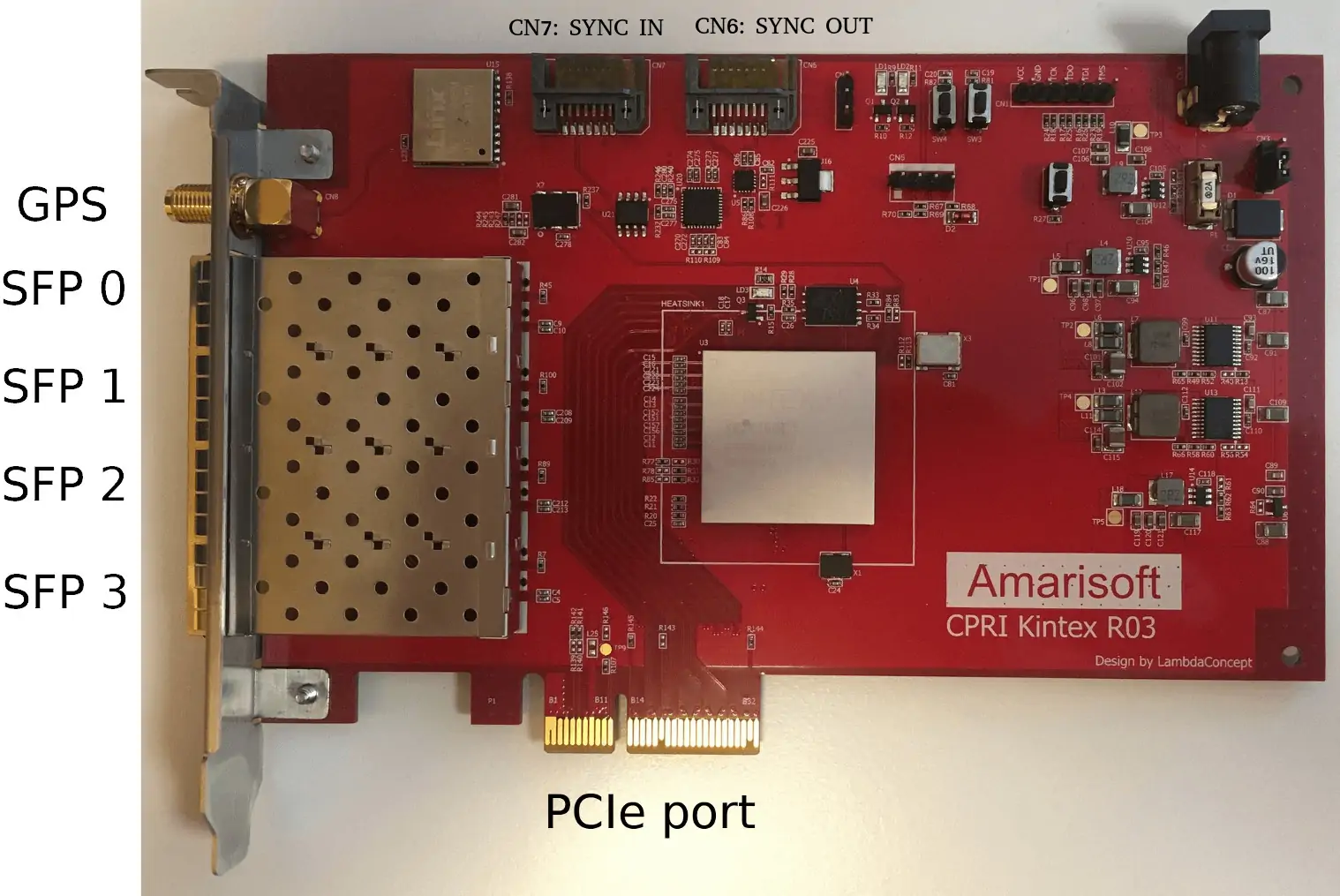
Figure 8.1
8.2.1 PPS/Clock connectors
Clock sync connectors
CN7CLK_IN Input to sync this board as slave.
CN6CLK_OUT Output to use this board as master for other CPRI board
On each SATA connector:
pin 1,4,7GND
pin 2,3AC coupled LVDS 122.88MHz clock
pin 5,6DC coupled CMOS (3V3) Pulse per Second signal 6=positive side
9 Remote API
SDR driver implements the trx remote API.
Message definition:
commandtrx.commandOptional string. Can be:
- clock_tune
- cpri_rx_delay
- cpri_tx_delay
Exemple:
{
    "message": "trx",
    "command": "clock_tune"
}
Here are the additional request and response field depending on command value:
9.1 clock_tune
Request fields:
offsetOptional number. If
commandisclock_tune, defines the clock drift to set in ppm.
9.2 cpri_rx_delay
Request fields:
rf_porttrx.rf_portInteger. Defines RF port to set and/or get.
cpri_rx_delaytrx.cpri_rx_delayOptional number. Update cpri_rx_delay in microseconds.
Response fields:
cpri_rx_delaytrx.cpri_rx_delayCurrent cpri_rx_delay in microseconds
9.3 cpri_tx_delay
Request fields:
rf_porttrx.rf_portInteger. Defines RF port to set and/or get.
cpri_tx_delaytrx.cpri_tx_delayOptional number. Update cpri_tx_delay in microseconds
Response fields:
cpri_tx_delaytrx.cpri_tx_delayCurrent cpri_tx_delay in microseconds. Note that the delay with PPS won’t be affected. This will only affect the IQ signal inside CPRI frames.
10 Change history
10.1 Version 2025-12-12
- Added
dev_ref_portsconfiguration parameter
10.2 Version 2025-06-13
- Added
rx_chan_mappingconfiguration parameter
10.3 Version 2024-09-13
- Added
cpri_rx_dbmparameter
10.4 Version 2024-06-14
- Added remote API support
10.5 Version 2023-09-08
- Added NUMA support