VoWiFi (Voice over WiFi)
This tutorial is to show how to setup, configure and operate VoWiFi (Voice over WiFi) with Amarisoft Callbox. What is VoWiFi ? Simply put, it is IMS Voice Call through WiFi without using cellular network like LTE or NR. Putting it other way, in terms of high level functionality is similar to VoLTE (Voice over LTE) or VoNR (Voice or NR), the only difference is the type of communication channel being used for the IMS voice call. As name implies, WiFi channel (instead of LTE or NR) is used for VoWiFi.
Why it requires any special equipment to test ? Everybody would have at least one WiFi AP(Access Point) at home. Can I just use it for the test ? NO, the situation is not so simple. IMS based Voice Call service provided by Carriers (Network Operators) require very sophiticated security mechanism which is almost same level as the security mechanism in cellular network. To provide this security mechanism over WiFi network, the call should go through a special gateway called ePDG (evolved Packet Gateway) in LTE . This is why you need special solution for VoWiFi testing. In orther words, you need a special test setup that support ePDG. Amarisoft Callbox has built in ePDG as part of MME(Core Network Package).
The overall procedure for VoWIFI can be illustrated as follows. IMS/SIP procedure happening at the last step is same as regular IMS/SIP voice call. The main difference between VoWiFi and regular IMS/SIP voice call (e.g, VoLTE or VoNR) is the procedure happening before the IMS/SIP procedure.
In case of VoWiFi, following unique procedure happens before IMS/SIP voice call establishment
- IKEv2 (Internet Key Exchange) : Handshaking procedure to authenticate and security setup to ePDG. This is an equivalent to Authentication, Security Mode Command procedure in cellular network (e.g, LTE, NR network)
- Establishing IPSec Tunnels : UE and ePDG establishes IPsec tunnel based on the security settings configured during IKE, through which IMS/SIP traffic is going through.
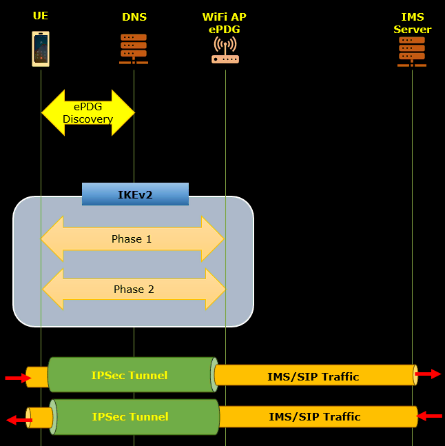
Table of Contents
Introduction
Voice over WiFi (VoWiFi) represents a significant advancement in telecommunications, enabling voice calls over WiFi networks through the IP Multimedia Subsystem (IMS) framework rather than relying on traditional cellular technologies like LTE or NR. VoWiFi leverages the robust, packet-based architecture of IMS and the flexibility of WiFi connectivity to deliver high-quality voice services, particularly in environments where cellular coverage is weak or unavailable. Unlike VoLTE (Voice over LTE) or VoNR (Voice over NR), VoWiFi requires the integration of specialized security mechanisms, such as Internet Key Exchange version 2 (IKEv2) and IPSec tunneling, to ensure carrier-grade security and authentication that matches the rigor of cellular networks. This is achieved through the involvement of a N3IWF (Non-3GPP InterWorking Function), which acts as a secure bridge between the user's WiFi connection and the operator's core network. Testing and operating VoWiFi thus necessitate a sophisticated setup, including equipment like the Amarisoft Callbox, which comes with integrated N3IWF functionality as part of its Core Network Package. Understanding the interplay of these technologies—SIP/IMS signaling, IKEv2 handshakes, secure IPSec tunnels, and the role of the ePDG—is critical for successfully configuring and operating VoWiFi services. This tutorial provides a comprehensive guide to setting up, configuring, and operating VoWiFi using Amarisoft Callbox, elucidating the detailed technical processes involved and the significance of each architectural component within the broader telecommunications ecosystem.
-
Context and Background
- Voice over WiFi (VoWiFi) is an IMS-based voice service that allows users to make and receive voice calls using WiFi networks instead of cellular radio access (LTE/NR).
-
Key Architectural Components:
- IMS (IP Multimedia Subsystem): The core framework for delivering IP-based voice and multimedia services.
- ePDG (Evolved Packet Data Gateway): Securely connects the WiFi network to the mobile operator’s core network, handling authentication and encryption.
- Amarisoft Callbox: A comprehensive test platform with built-in core network functions, including ePDG, MME, and IMS.
-
Security and Authentication:
- VoWiFi requires secure authentication and encrypted communication via IKEv2 and IPSec tunnels, replicating cellular-grade security over WiFi.
-
Technical Challenges:
- Unlike basic WiFi access, VoWiFi must implement carrier-grade authentication and security, which mandates specialized equipment and configuration.
-
Relevance and Importance
- VoWiFi expands voice service coverage, especially in areas with limited cellular signal, by utilizing existing WiFi infrastructure.
- It is essential for operators and testers to understand the unique security and signaling requirements to ensure interoperability and compliance with 3GPP and IETF standards.
- The Amarisoft Callbox enables comprehensive testing and validation of VoWiFi features, accelerating development and deployment cycles.
-
Learning Outcomes
- Gain hands-on experience setting up and configuring VoWiFi on Amarisoft Callbox, including N3IWF and IMS components.
- Understand the end-to-end flow of a VoWiFi call: from WiFi attachment, IKEv2 authentication, IPSec tunnel establishment, to IMS/SIP-based call setup.
- Learn to troubleshoot common VoWiFi deployment issues, particularly those related to security, authentication, and signaling.
-
Prerequisite Knowledge
- Familiarity with IP networking concepts, including WiFi configuration and basic network troubleshooting.
- Understanding of cellular core network architecture, particularly IMS, MME, and SIP signaling.
- Basic knowledge of security protocols such as IKEv2 and IPSec is beneficial.
- Experience with Amarisoft Callbox or similar telecom test platforms will aid in following the tutorial steps effectively.
Summary of the Tutorial
This tutorial outlines the procedures for conducting a Voice over WiFi (VoWiFi) test using a WiFi Access Point (AP) and an N3IWF implemented via Amarisoft callbox. The test validates the establishment of secure IPsec tunnels using IKEv2 protocol and the successful registration and operation of IMS voice services over WiFi without involvement from eNB/gNB radio access.
-
Test Setup:
- Configure a WiFi AP, either by using a built-in PC WiFi module or your own AP, ensuring proper SSID and IP address assignment (e.g., 10.42.0.1).
- Implement ePDG functionality as part of the MME using Amarisoft, binding to the APs IP address.
- Modify relevant configuration files: gnb-sa-vowifi.cfg, ims.default-voWifi.cfg, mme-ims-voWifi.cfg, and ue_db-ims-vowifi.cfg to enable VoWiFi parameters and ensure correct PLMN and SIM settings.
- Run ‘lte service’ on the gNB/eNB and ensure correct PLMN configuration, but no further eNB/gNB involvement is needed.
-
Test Execution Procedure:
- Connect the UE (User Equipment) to the configured WiFi AP, confirming SSID visibility to ensure successful connection and initiation of the ePDG process (IKEv2).
- Initiate a voice call from the UE to the IMS Voice Loopback number to verify call connectivity over WiFi.
-
Detailed IKEv2/IPsec Tunnel Establishment:
- Capture and analyze logs from MME and IMS (eNB log is optional).
- Follow the IKEv2 negotiation sequence:
- Phase 1 Initiation: Initiator proposes cryptographic parameters and NAT traversal options.
- Phase 1 Response: Responder selects encryption/integrity parameters (e.g., AES-CBC, HMAC-SHA1) and confirms NAT traversal capabilities.
- Key Derivation: Keys (SK_d, SK_ai, etc.) are derived for securing further exchanges.
- Phase 2 Exchange: Authentication is performed using EAP-AKA with identity verification (e.g., FQDN "ims").
- Phase 2 Completion: Both initiator and responder complete authentication, and the responder signals EAP success.
- Child SA negotiation is performed to establish IPsec tunnels for both IPv4 and IPv6 traffic, with detailed traffic selectors, security parameter indexes (SPIs), and cryptographic keys assigned for each direction.
- Responder finalizes the Child SA, providing configuration payloads such as assigned internal IP addresses, DNS, and P-CSCF addresses for IMS operation.
-
SIP Registration and Call Setup:
- After IPsec SAs are established, the UE initiates SIP registration to the IMS core.
- If registration is successful, the UE proceeds to send a SIP INVITE for establishing a VoWiFi call.
- If SIP registration fails, review the IKE and IPsec tunnel setup steps for issues.
-
Log Analysis:
- Review packet captures to verify correct IKEv2 exchanges, successful EAP-AKA authentication, proper IPsec tunnel establishment, and the presence of SIP REGISTER and INVITE messages.
- Ensure that the full content of logs is analyzed for comprehensive troubleshooting.
Summary: The procedure verifies end-to-end VoWiFi operation by establishing a secure connection over WiFi using ePDG and IPsec, authenticating the UE with EAP-AKA, and validating IMS call flow through SIP signaling—all without radio access network involvement.
Test Setup
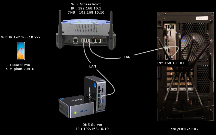
Test setup for this tutorial is as shown below.
For this test, a WiFi Access Point (AP) is required. You may use your own AP connected to Callbox PC if you can configure it as described here.
Key Configuration Parameters
Followings are important configuration parameters for this tutorial. You may click on the items for the descriptions from Amarisoft documents.
- ims_vops_eps
- ims_vops_5gs_n3gpp
- epdg
- bind_addr
- certificate
- esp_duration
- ike_duration
- omit_auth_in_first_auth_rsp
- ike_encryption_algo_list
- ike_integrity_algo_list
- ike_prf_list
- ike_dh_group_list
- esp_encryption_algo_list
- esp_integrity_algo_list
- esp_dh_group_list
- dpd_timer_value
- mobike
- ike_generate_error
- idr_for_emergency
- dont_fragment
- additional_ue_auth_type
Test 1 : Commercial UE as DUT
The purpose of this test is to configure and perform a test using a commercial UE.
Configuration
I used the enb-plmn-20810.cfg which is modified from enb.default.cfg

I also used ims-epdg.cfg modified from ims.default.cfg and mme-ims-epdg.cfg modified from mme-ims.cfg. The default ue_db-ims.cfg was replaced by ue_db-ims-epdg.cfg in this test.

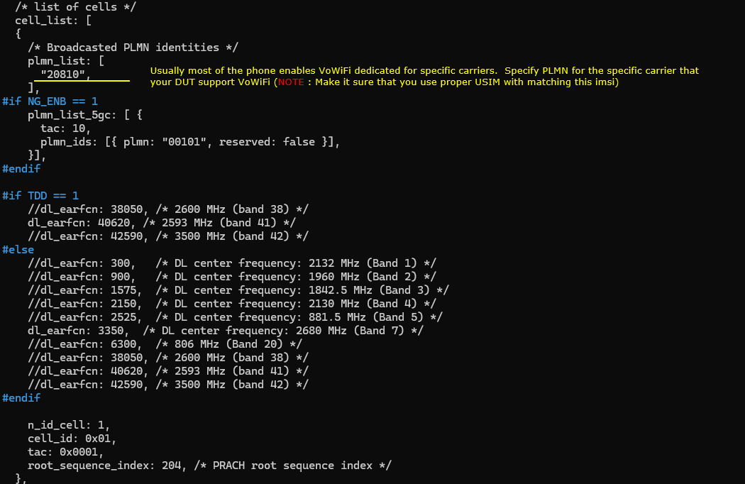
Change the configuration in enb-plmn-20810.cfg as follows.
I changed plmn because usually most of the phone enables VoWiFi dedicated for specific carriers. Specify PLMN for the specific carrier that your DUT support VoWiFi (
In this example, the broadcast PLMN is set to 20810. This means the test cell is configured to behave like the network of that specific carrier. The DUT will check this PLMN and decide whether VoWiFi-related carrier configuration can be applied.
You also need to make sure that the USIM matches the configured PLMN. For example, if the cell broadcasts PLMN 20810, the IMSI in the USIM should belong to the same PLMN range. Otherwise, the DUT may attach to the network, but VoWiFi may not be enabled because the phone does not recognize the network as a supported VoWiFi carrier.
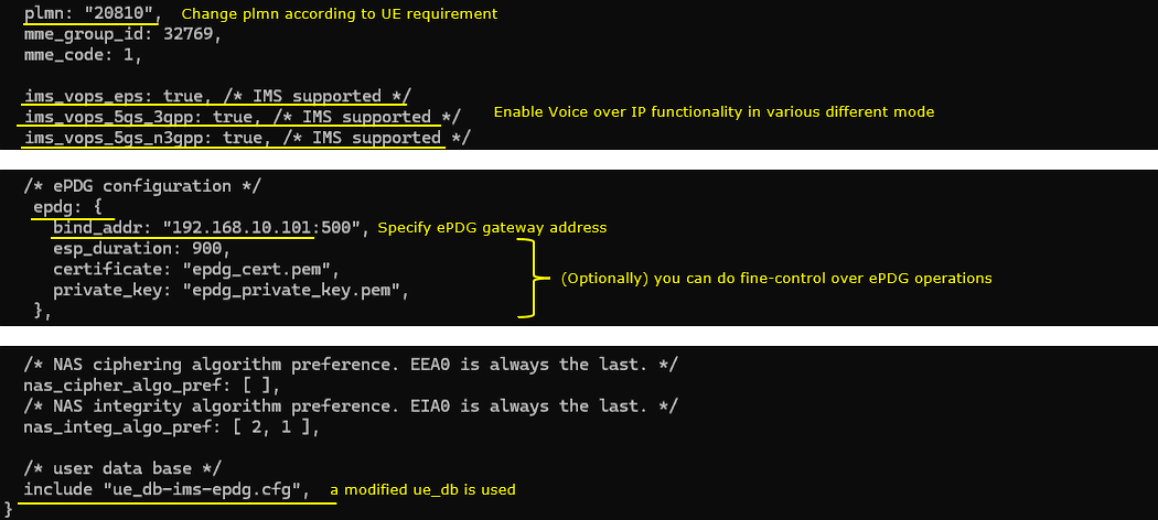
In mme-ims-epdg.cfg enable all the parameters that are related to VoWiFi. ims_vops_eps and ims_vops_5gs_n3gpp are the essential parameters for this test, but ims_vops_5gs_3gpp is also enabled as well for possible other test (e.g, VoNR). Also note that plmn is changed from the default since the plmn on cell configuration is changed.
Then add epdg configuration. In this test, we configured a single parameter bind_addr in epdg object. This is the most basic configuration and you can fine controll the behavior of ePDG in various different way using the configuration parameters listed here
In this example, the PLMN is changed to 20810. This should match the PLMN used in the cell configuration. If the cell broadcasts a different PLMN, the MME/IMS/ePDG configuration should be changed accordingly. Otherwise, the UE may not recognize the network as the intended VoWiFi carrier network.
The following IMS voice support parameters are enabled.
ims_vops_eps is set to true. This indicates that IMS voice over EPS is supported.
ims_vops_5gs_3gpp is set to true. This indicates that IMS voice over 5GS through 3GPP access is supported.
ims_vops_5gs_n3gpp is set to true. This indicates that IMS voice over 5GS through non-3GPP access is supported. For this VoWiFi test, ims_vops_eps and ims_vops_5gs_n3gpp are the essential parameters. ims_vops_5gs_3gpp is also enabled in this example for possible other tests, such as VoNR.
Then add the ePDG configuration.
In this test, only the basic ePDG configuration is used. The bind_addr parameter is configured as 192.168.10.101:500. This specifies the local IP address and port where the ePDG listens for IKE/IPsec connection requests from the UE.
The certificate and private_key parameters specify the certificate files used by the ePDG. In this example, epdg-cert.pem and epdg-private-key.pem are used.
This is the minimum level of ePDG configuration for this example. Amarisoft also provides many other ePDG configuration parameters, so you can fine-control the ePDG behavior depending on the test requirement.
Finally, the user database file is changed to ue_db-ims-epdg.cfg. This modified UE database should include the USIM and IMS-related information required for this VoWiFi/ePDG test.
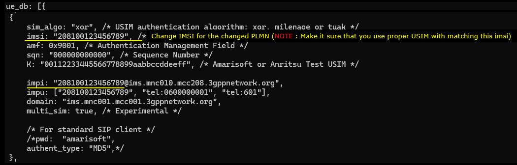
Lastly change (or add) UE sim information in ue_db-ims-epdg.cfg to match with your SIM card.
In this example, the IMSI is set to 208100123456789. The first part of the IMSI should match the PLMN used in the previous configurations. Since the PLMN was changed to 20810, the IMSI is also configured with the same MCC/MNC value. This is important because the DUT usually enables VoWiFi only when the SIM profile and the detected carrier profile match.
The sim_algo parameter defines the USIM authentication algorithm. In this example, it is set to xor. Depending on your SIM card, this can be xor, milenage, or tuak. The K value should also match the secret key programmed in the USIM. If this value does not match, authentication will fail.
The opc and amf values are also part of the authentication configuration. These values should be configured according to the SIM card that you are using. In this example, opc is set to 00000000000000000000000000000000 and amf is set to 9001.
The IMS-related identity should also be changed to match the configured IMSI and PLMN. In this example, impi is set to [208100123456789@ims.mnc010.mcc208.3gppnetwork.org](mailto:208100123456789@ims.mnc010.mcc208.3gppnetwork.org), and impu includes sip:[208100123456789@ims.mnc010.mcc208.3gppnetwork.org](mailto:208100123456789@ims.mnc010.mcc208.3gppnetwork.org) and tel:0600000001. The domain is set to ims.mnc001.mcc001.3gppnetwork.org in the example configuration, but in a real test it should be aligned with the PLMN and IMS configuration used in your setup.
NOTE: Make sure the IMSI, PLMN, authentication parameters, and IMS identities are consistent with each other. Otherwise, the UE may pass basic cellular registration, but VoWiFi registration through ePDG and IMS may still fail.
Perform the test
Since this test is for Voice over WiFi, the eNB or gNB side does not do much during the actual VoWiFi procedure. The voice service is carried through WiFi, ePDG, IPsec, and IMS. So the radio cell is mainly used to provide the required carrier environment and PLMN information to the DUT.
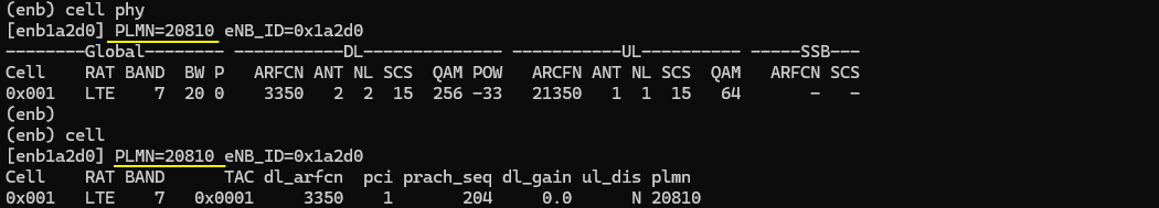
Start the LTE service as usual and make sure the cell is running properly. Then check the cell information from the Amarisoft screen.
In this example, the cell is configured with PLMN 20810. This confirms that the eNB is broadcasting the PLMN that was configured in the previous steps. The same PLMN should also be used in mme-ims-epdg.cfg and in the UE database configuration.
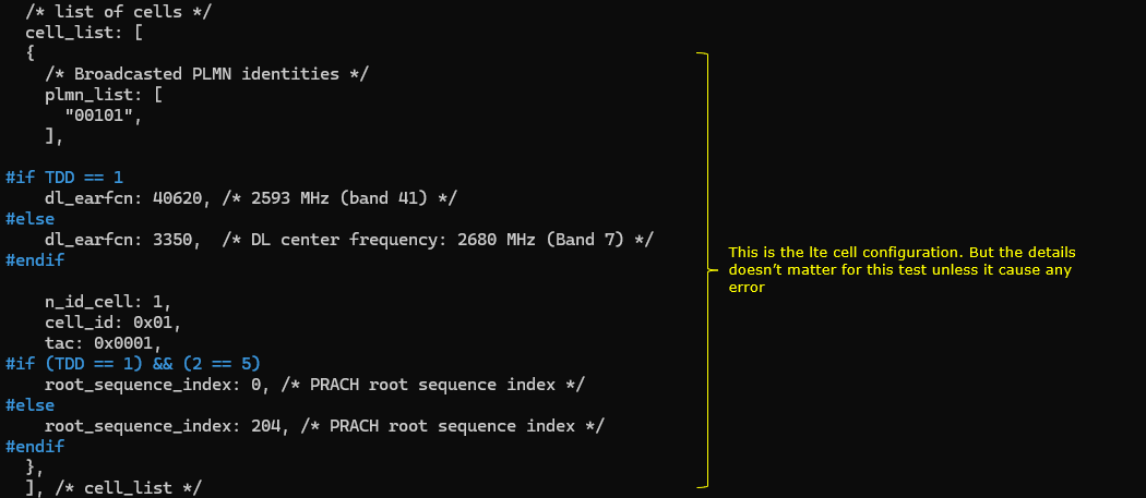
The cell_phy output shows the LTE cell information. In this example, the cell is LTE Band 7 with 20 MHz bandwidth. The downlink EARFCN is 3350 and the uplink EARFCN is 21350. The PLMN shown in the header is 20810.
The cell output also confirms the same PLMN. It shows TAC 0x0001, DL EARFCN 3350, PCI 1, PRACH root sequence index 204, and PLMN 20810.
At this point, the most important thing is not the detailed radio configuration itself. The important thing is to confirm that the DUT can see the expected carrier PLMN from the LTE cell. Once this part is correct, the remaining VoWiFi procedure is mainly handled through WiFi, ePDG, IPsec, and IMS.
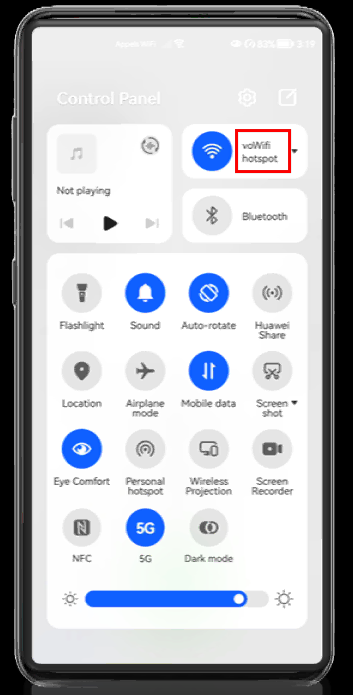
Wait until UE WiFi get connected to the WiFi AP configured for ePDG. If the UE shows the configured SSID properly, it indicates UE went through the initial ePDG process (IKEv2) properly.
In this example, the UE is connected to the WiFi SSID named voWifi hotspot. This indicates that the UE has successfully connected to the WiFi access network that is prepared for the ePDG procedure.
Once the UE connects to this WiFi AP, the UE can start the initial VoWiFi procedure. In most cases, this means the UE starts the IKEv2 procedure toward the ePDG. Through this procedure, the UE establishes the secure IPsec path that will later be used for IMS signaling over WiFi.
So, at this step, the important point is to confirm that the DUT shows the expected SSID. If the configured SSID is shown properly on the UE, it is a good indication that the UE has passed the initial WiFi connection step and started or completed the initial ePDG connection procedure properly.
After this, you can move to the Amarisoft log and check whether the IKEv2 and ePDG-related messages are observed as expected.
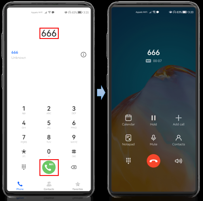
Now try to make a voice call to the IMS voice loopback number and check whether the call gets connected.
In this example, the UE dials 666. This is the IMS voice loopback number configured in the Amarisoft IMS test setup. When the call is made, the phone shows the VoWiFi icon on the call button. This indicates that the outgoing call is being attempted through WiFi calling, not through normal LTE voice.
After pressing the call button, the call screen shows that the call to 666 is connected. The call timer is running, which means the IMS voice session has been established successfully.
At this point, the important thing is to confirm two things. First, the UE should show the WiFi calling indication during the call. Second, the call should stay connected to the loopback number without being released immediately.
If this works, it means the main VoWiFi path is working properly. The UE has connected to WiFi, established the ePDG/IPsec path, completed IMS registration, and successfully created an IMS voice session over WiFi.
Log Analysis
Unlike the log analysis for other tutorial, the log analysis in this tutorial is NOT about 3GPP since the traffic is going through the non-3GPP network which is WiFi and ePDG.
First of all, for this test you need to collect log from almost all components - MME, IMS for this test. ENB is not directly involved in this test, but no harm to collect the log. (
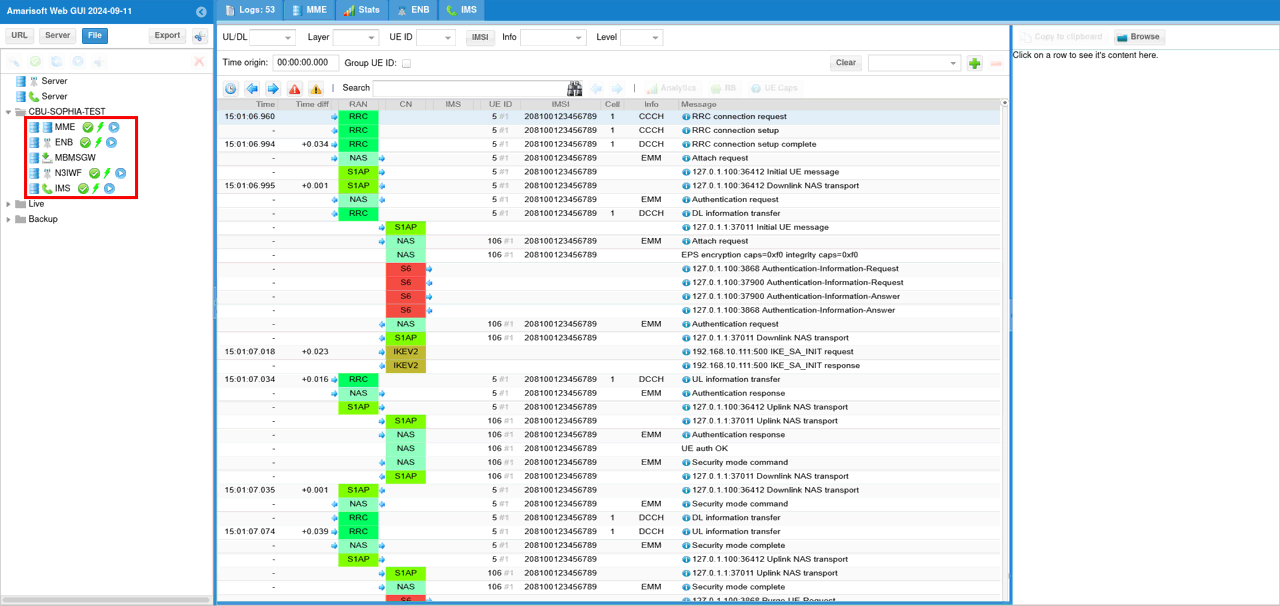
The first two IKEv2 message shown here may not be seen in every test since they are failed attempt for SA_INIT.
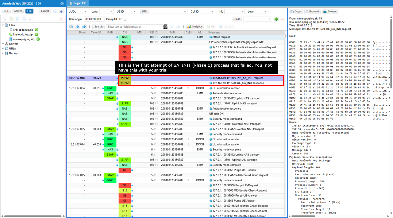
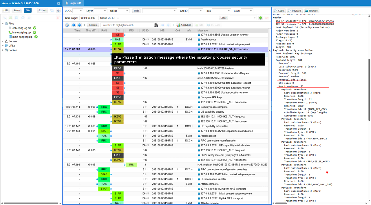
This is the first message in an IKE Phase 1 negotiation (Main Mode) where the initiator proposes multiple combinations of cryptographic algorithms and parameters for securing the IKE Security Association (SA), along with NAT traversal capabilities.
Short summary of the contents of the message are :
- IKE Phase 1 Initiation: The Exchange type: 2 and the presence of Security Association and Key Exchange payloads indicate this is the start of an IKE Phase 1 negotiation.
- Security Proposals: The initiator is offering a variety of options for encryption (ENCR), pseudo-random functions (PRF), integrity/authentication (INTEG), and Diffie-Hellman groups (D-H) to the responder.
- NAT Traversal: The inclusion of NAT_DETECTION_SOURCE_IP and NAT_DETECTION_DESTINATION_IP notify messages signals that the initiator is prepared to handle Network Address Translation (NAT) issues that might arise during the VPN connection establishment.
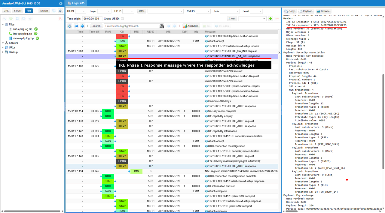
This is an IKE Phase 1 response message where the responder acknowledges the initiator's proposals and selects specific security parameters (AES-CBC encryption, HMAC-SHA1 integrity, and DH Group 14) for establishing the IKE Security Association (SA). It also includes NAT traversal capabilities.
Short summary of the contents of the message are :
- IKE Phase 1 Response:
- The Exchange type: 2 and Flags: 32 (R) clearly indicate this is a response message in the second step of IKE Phase 1 negotiation.
- The responder's SPI (0x1BEC5D6ABED9DB4E in this case) is now present, signifying its participation in the SA establishment.
- Security Parameter Selection
- The Security Association payload with Num transforms: 4 shows the responder has chosen a specific set of security algorithms and parameters from the initiator's proposals. which includes
- ENCR_AES_CBC for encryption with a 128-bit key.
- PRF_HMAC_SHA1 for generating pseudo-random keys.
- AUTH_HMAC_SHA1_96 for integrity and authentication.
- DH_GROUP_14 for the Diffie-Hellman key exchange, which will be used to create the shared secret key for the IKE SA.
- Key Exchange Payload:
- This payload contains the responder's Diffie-Hellman public value, essential for completing the key exchange process with the initiator.
- NAT Traversal:
- The presence of NAT_DETECTION_SOURCE_IP and NAT_DETECTION_DESTINATION_IP notify messages indicates that the responder is also prepared to handle potential NAT issues in the network.
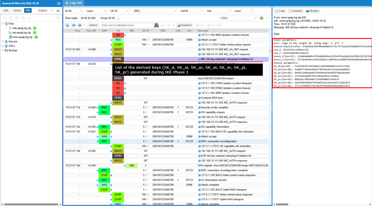
This is the list of the derived keys (SK_d, SK_ai, SK_ar, SK_ei, SK_er, SK_pi, SK_pr) generated during IKE Phase 1 (previous two steps).
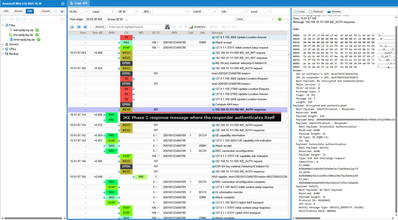
This is an IKE Phase 2 response message where the responder authenticates itself using EAP-AKA and confirms its identity as "ims."
Short summary of the contents of the message are :
- IKE Phase 2 Response: The Exchange type: 3 and Flags: 32 (R) indicate this is a response within IKE Phase 2, likely following a Phase 2 initiation message from the initiator.
- Encrypted and Authenticated Payload: This payload carries the core of the message, protected by encryption and integrity checks derived from the IKE SA established in Phase 1.
- Identification: The responder identifies itself using an FQDN (Fully Qualified Domain Name) "ims."
- EAP-AKA Authentication: This is the key part of the message. The responder is using EAP-AKA, a specialized authentication method commonly used in mobile networks, to prove its identity to the initiator. The payload includes:
- EAP AKA Challenge request: This indicates the responder is likely requesting authentication information from the initiator.
- AT_RAND, AT_AUTN, AT_MAC: These are specific parameters used in the EAP-AKA authentication exchange.
- Device Identity Notification: The DEVICE_IDENTITY notification might convey additional information about the responder's device type or capabilities.
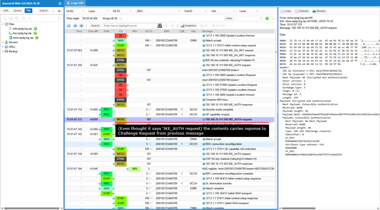
This is an IKE Phase 2 response message where the initiator completes the EAP-AKA authentication exchange by providing its response to the challenge issued by the responder.
Short summary of the contents of the message are :
- IKE Phase 2 Response: The Exchange type: 3 and Flags: 8 (I) indicate this is a response within IKE Phase 2, sent by the initiator.
- Encrypted and Authenticated Payload: This payload carries the core of the message, protected by the security mechanisms negotiated in Phase 1.
- EAP-AKA Authentication: This is the key part of the message. The initiator is completing the EAP-AKA authentication exchange initiated by the responder in the previous message. The payload includes:
- EAP AKA Challenge response: This signifies the initiator's response to the EAP-AKA challenge.
- AT_RES: The "result" parameter within EAP-AKA, containing the initiator's calculated response to the challenge.
- Attribute type unknown: 134: This might indicate a vendor-specific or non-standard EAP-AKA attribute.
- AT_MAC: The message authentication code, ensuring the integrity and authenticity of the EAP-AKA response.
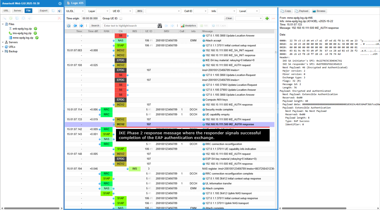
This is an IKE Phase 2 response message where the responder signals successful completion of the EAP authentication exchange.
Short summary of the contents of the message are :
- IKE Phase 2 Response: The Exchange type: 3 and Flags: 32 (R) indicate that this is a response within IKE Phase 2, sent by the responder.
- Encrypted and Authenticated Payload: This payload carries the core of the message, protected by the security mechanisms negotiated in Phase 1.
- EAP Success: This is the key part of the message. It signals that the EAP authentication exchange, likely initiated by the responder in a previous message, has concluded successfully. This means both sides have successfully proven their identities to each other.
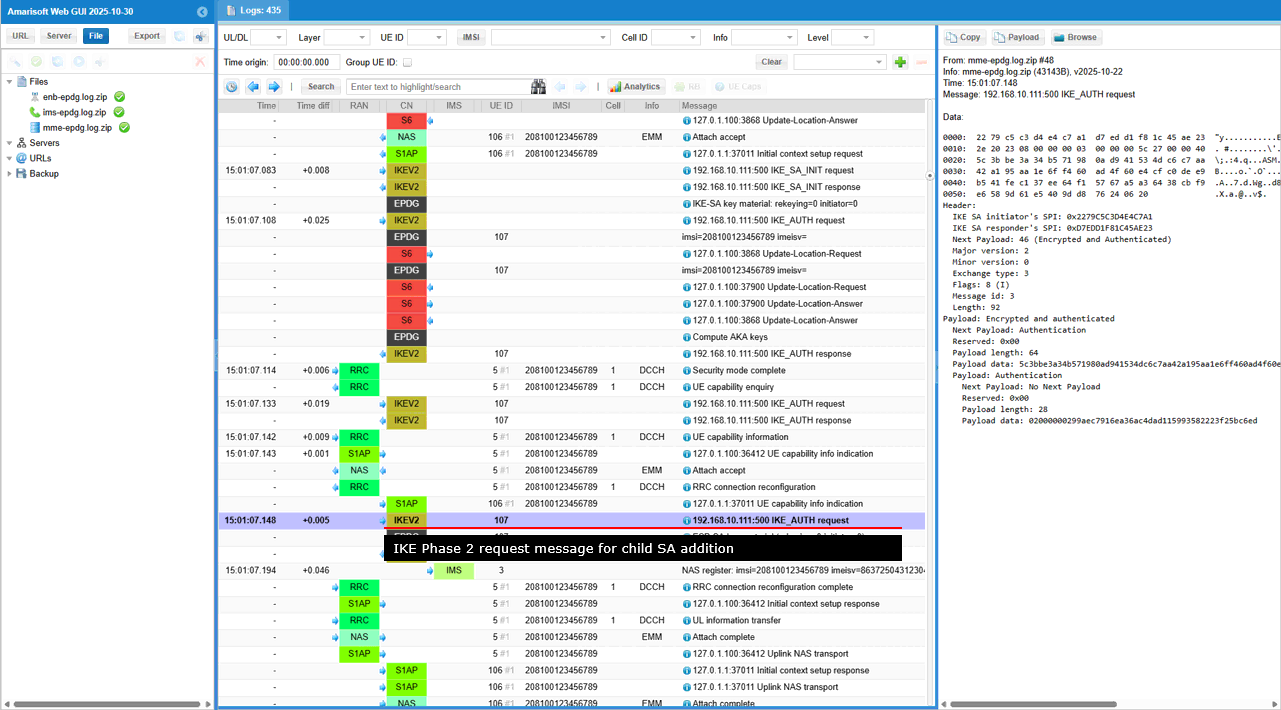
This is an IKE Phase 2 request message where the initiator is for adding the Child SA negotiation and potentially including additional configuration requests. (
- IKE Phase 2 Request: The Exchange type: 3 and Flags: 8 (I) indicate this is a request within IKE Phase 2, sent by the initiator.
- Encrypted and Authenticated Payload: This payload carries the core of the message, protected by the security mechanisms negotiated in Phase 1.
- Authentication Payload: This payload likely contains authentication information related to the Child SA negotiation. It could be a confirmation of the responder's authentication or some additional authentication data related to the Child SA itself.
- No Next Payload: This suggests that this might be the final message in this particular IKE exchange, or that any further payloads are optional and not included in this specific message.
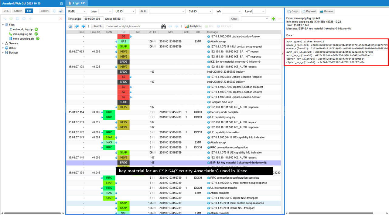
This is the list of key material for an ESP Security Association (SA) used in IPsec. This process is likely part of establishing a secure IPsec tunnel within an existing IKE session.
Establishing Transport pipe for SA
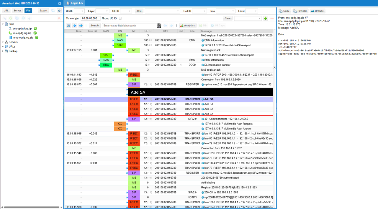
Once all the steps of IKE and SA addition are properly done, UE is supposed to send SIP Register and complete all the registration process. (
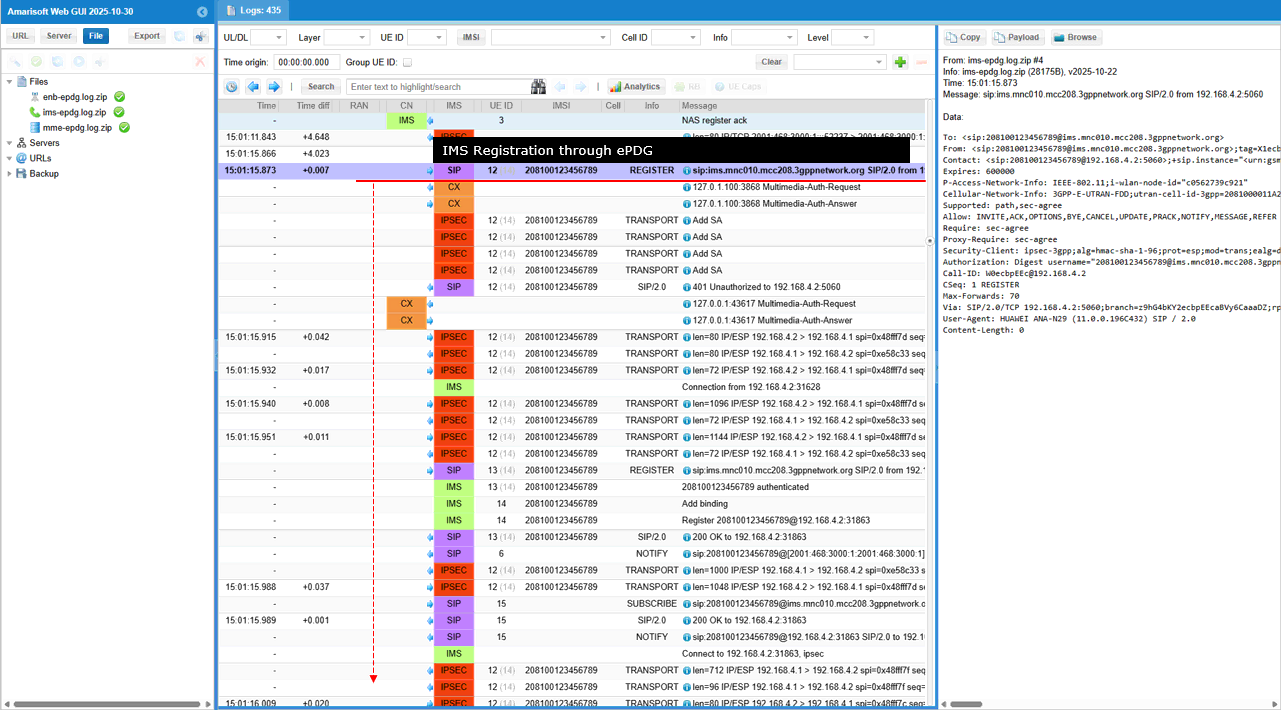
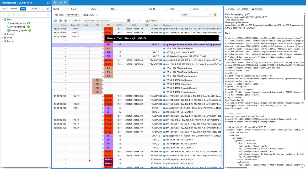
Once SIP Registration went through properly and you make a call from the UE, UE should send SIP INVITE message and go through the call setup process.
Test 2 : Amarisoft UEsim as DUT
The purpose of this test is to configure and perform a test using the Amarisoft UEsim as DUT. Amarisoft UEsim does not have any WiFi PHY/MAC, this test goes through IP layer between ePDG client on UEsim and ePDG server on Callbox.
Configuration
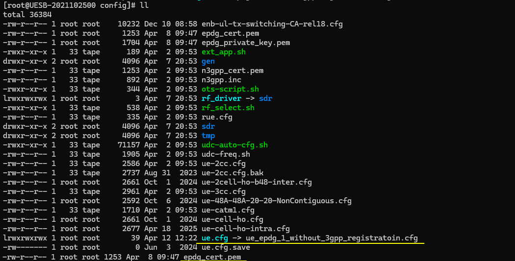
I used the enb_epdg_1_without_3gpp_registratoin.cfg which is modified from enb.default.cfg

I also used ims_epdg_1_without_3gpp_registratoin.cfg modified from ims.default.cfg and mme_epdg_1_without_3gpp_registratoin.cfg modified from mme-ims.cfg. You need to prepare key files that are used for the test as well : epdg_cert.pem and epdg_private_key.pem

I used the ue_epdg_1_without_3gpp_registratoin.cfg which is modified from ue.default.cfg and you need to prepare the key file for the UE : epdg_cert.pem
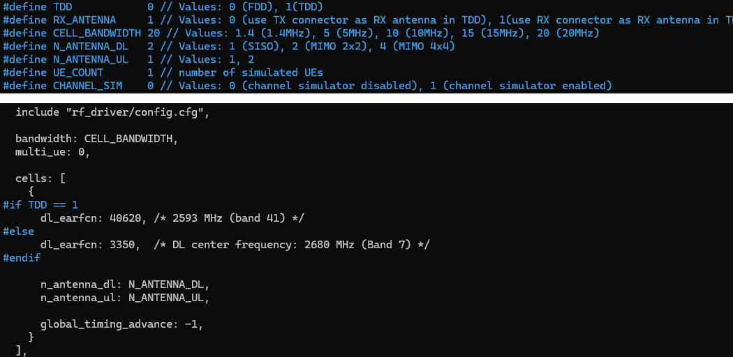
Change the configuration in enb_epdg_1_without_3gpp_registratoin.cfg as follows.
This part explains that the LTE physical layer configuration is not critical for this test. The purpose of the test is ePDG connectivity over IP, so the radio parameters are only needed to keep the eNB running without error. Any valid configuration can be used as long as the eNB operates normally.
Overall, this configuration is just a stable baseline to keep the LTE cell running. The actual focus of the test is the IP-level interaction between UEsim and the ePDG on the Callbox, not the radio behavior.
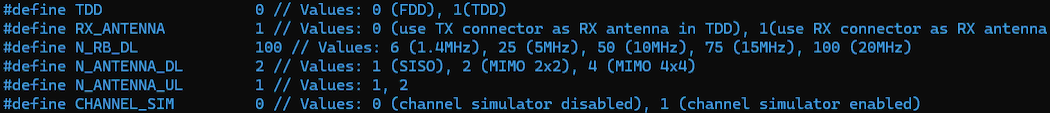
This part defines the LTE cell configuration that the eNB will broadcast. The purpose is to make the cell operational so that the UE can attach, but the detailed parameters are not important for this test.(
Overall, this configuration ensures that the LTE cell can start and accept UE attachment. The exact values are not critical for this test as long as the UE can successfully connect and proceed to the IP layer where the ePDG functionality is being tested.
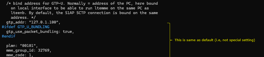
mme_epdg_1_without_3gpp_registratoin.cfg configures the core network related parameters on the eNB side. It mainly defines how the eNB connects to the MME and how user plane traffic is handled, but there is nothing special for this test.
The gtp_addr is set to 127.0.1.100. This means the GTP-U interface is bound to a local IP address on the same machine. This setup is used when LTE eNB and MME are running on the same PC, so the user plane traffic does not go out to an external network.
The S1AP SCTP connection is also bound to the same local address. This allows both control plane and user plane connections to operate internally within the same system.
The plmn is set to "00101". This must match the PLMN broadcast by the cell so that the UE can attach properly.
Overall, this configuration is a standard default setup for running eNB and MME on the same machine. It ensures that both control plane and user plane connections work correctly, but it does not introduce any special behavior for the ePDG test.
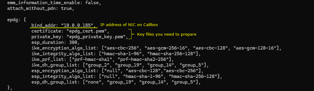
This part configures the ePDG server on the Callbox. This is the core of the test because it enables IPSec tunneling between UEsim and the network.
The epdg block activates the ePDG functionality. This allows the Callbox to behave as an ePDG server and terminate IPSec tunnels coming from the UE.
The bind_addr is set to 10.0.0.185. This is the IP address of the NIC on the Callbox. UEsim connects to this address to establish the IPSec tunnel.
The certificate and private_key define the security identity of the ePDG. These files are used during IKEv2 authentication. The UE verifies the certificate and establishes a secure session using the private key on the server side.
The esp_duration is set to 300. This defines the lifetime of the IPSec Security Association. After this time, the tunnel is rekeyed to maintain security.
The ike_encryption_algo_list defines the encryption algorithms supported during the IKE phase. This is used when negotiating how the control plane of the IPSec tunnel is protected.
The ike_integrity_algo_list defines the integrity protection algorithms for IKE. This ensures that signaling messages are not modified during exchange.
The ike_prf_list defines the pseudo random functions used for key generation during IKE negotiation.
The ike_dh_group_list defines the Diffie-Hellman groups used for key exchange. This determines the strength of the key agreement process.
The esp_encryption_algo_list defines the encryption algorithms used for the actual user plane traffic inside the IPSec tunnel.
The esp_integrity_algo_list defines the integrity protection for ESP packets. This ensures that the user plane data is not tampered with.
The esp_dh_group_list defines the DH groups used when rekeying the ESP session.
Overall, this configuration defines how the IPSec tunnel is created and secured. The UE and ePDG negotiate these parameters during IKEv2 exchange. This is the key part of the test because all traffic between UEsim and the network flows through this secure tunnel.
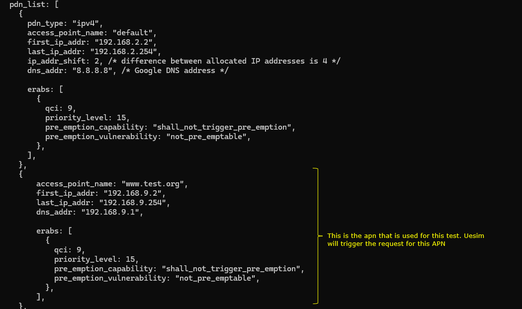
This part defines the PDN configuration on the core network side. It specifies how IP addresses are assigned and which APN is used when the UE requests connectivity.
The pdn_list contains multiple PDN profiles. Each profile represents an APN that the UE can request.
The first entry defines a default APN. It uses IPv4 addressing and assigns IP addresses from the range 192.168.2.2 to 192.168.2.254. The ip_addr_shift controls how addresses are incremented for multiple UEs. The dns_addr is set to 8.8.8.8, so the UE will use this DNS server after connection.
The erabs section defines the bearer configuration. The qci is set to 9, which corresponds to a default non-GBR data bearer. The priority and pre-emption settings define how this bearer behaves in terms of resource allocation.
The second entry defines the APN www.test.org. This is the APN used in this test.
When the UE sends the pdn_connect request with apn set to [www.test.org](http://www.test.org), the core network selects this PDN configuration.
The IP address is assigned from the range 192.168.9.2 to 192.168.9.254. This becomes the UE IP address inside the IPSec tunnel.
The dns_addr is set to 192.168.9.1. This is typically the gateway or DNS server inside the core network.
The erabs configuration is similar to the default case and provides a standard data bearer.
Overall, this configuration defines how the UE gets its IP address and network parameters after the ePDG tunnel is established. The key point is that the APN www.test.org must match the APN used in the pdn_connect command so that the correct PDN profile is selected.
In ue_epdg_1_without_3gpp_registratoin.cfg , followings are configured. This part configures the LTE cell parameters on the UEsim side. These settings are needed so that UEsim can run properly with the LTE environment, but they are not the main point of this test.
Overall, this is a basic LTE cell configuration for UEsim. Its role is just to keep the LTE side running correctly. For this test, the exact values are not very important as long as UEsim starts without error and can proceed to the IP-level ePDG procedure.
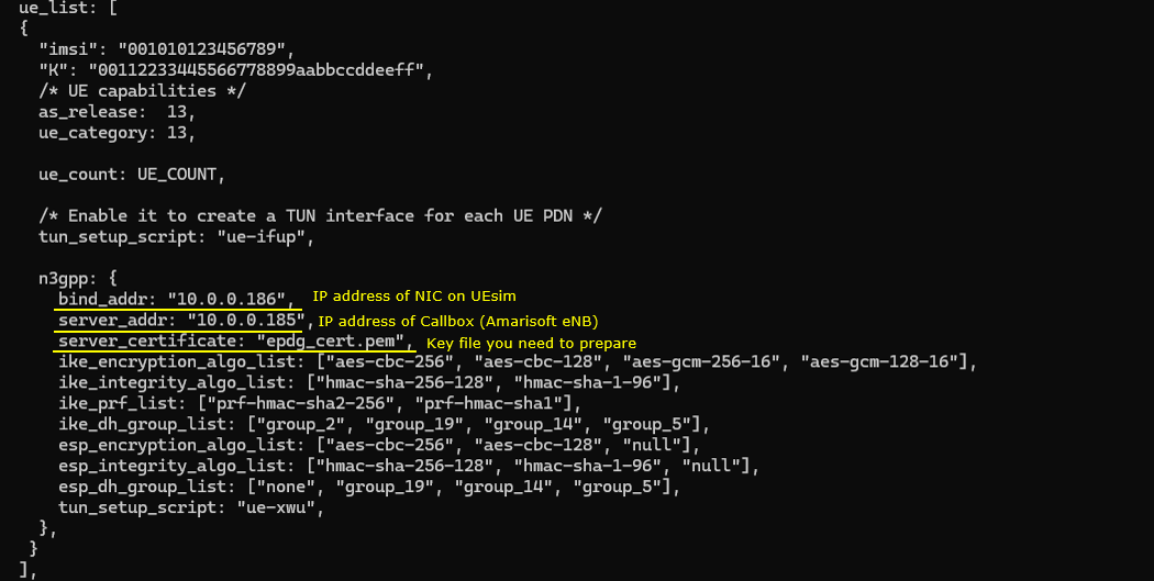
This part configures the UE profile and the ePDG client behavior on UEsim. This is important because it defines how the UE establishes the IPSec tunnel toward the ePDG on the Callbox.
The tun_setup_script is set to ue-ifup. This script creates a TUN interface for each PDN connection. This allows IP traffic from the UE to be routed through the virtual interface.
The n3gpp block enables non-3GPP access, which means the UE connects through ePDG instead of LTE user plane.
The bind_addr is set to 10.0.0.186. This is the IP address of the NIC on the UEsim side. The IPSec tunnel originates from this address.
The server_addr is set to 10.0.0.185. This is the IP address of the ePDG server on the Callbox. The UE connects to this address to establish the tunnel.
The server_certificate is set to epdg_cert.pem. This file is used by the UE to verify the identity of the ePDG during IKEv2 authentication.
The ike_encryption_algo_list defines the encryption algorithms used during IKE negotiation. The UE proposes these algorithms to the ePDG.
The ike_integrity_algo_list defines the integrity algorithms for IKE signaling.
The ike_prf_list defines the pseudo random functions used for key generation.
The ike_dh_group_list defines the Diffie-Hellman groups used for key exchange.
The esp_encryption_algo_list defines the encryption algorithms used for the IPSec data plane.
The esp_integrity_algo_list defines the integrity protection for ESP packets.
The esp_dh_group_list defines the DH groups used during ESP rekeying.
The tun_setup_script is set to ue-xwu. This script configures the TUN interface for the non-3GPP access case and connects it to the IPSec tunnel.
Overall, this configuration allows UEsim to behave as a UE connecting over Wi-Fi through ePDG. The UE establishes an IPSec tunnel using IKEv2, authenticates using the configured credentials, and then routes IP traffic through the tunnel into the EPC.
Key File Generation
In this test, we used a set of key files that are involved in the authetication process and those key files are provided with the configuration file. But you can generate your own key files if you want based on this document. An example of the key file generation process are shown below.
|
openssl genrsa -out ca.key 2048 openssl req -new -x509 -days 3650 -key ca.key -out ca.crt openssl req -newkey rsa:2048 -nodes -keyout epdg_private_key.pem -out epdg_cert.pem openssl x509 -req -extfile <(printf "subjectAltName=DNS:epdg.epc.mnc001.mcc001.pub.3gppnetwork.org") -days 3650 -in epdg_cert.pem -CA ca.crt -CAkey ca.key -CAcreateserial -out epdg_cert.pem openssl x509 -in epdg_cert.pem -text openssl rsa -in epdg_private_key.pem -text |
Followings are the description of each command and process of the key generation.
- openssl genrsa -out ca.key 2048
- This command generates a 2048-bit RSA private key for the Certificate Authority.
- ca.key is the file that stores the CA private key. This key is used to sign other certificates.
- openssl req -new -x509 -days 3650 -key ca.key -out ca.crt
- This command creates a self-signed CA certificate.
- -new means a new certificate request is created.
- -x509 means it generates a self-signed certificate instead of a CSR.
- -days 3650 sets the validity period to 10 years.
- -key ca.key specifies the private key used for signing.
- -out ca.crt is the output file for the CA certificate.
- openssl req -newkey rsa:2048 -nodes -keyout epdg_private_key.pem -out epdg_cert.pem
- This command generates a new RSA private key and a certificate signing request for the ePDG.
- -newkey rsa:2048 creates a new 2048-bit RSA key.
- -nodes means the private key is not encrypted with a passphrase.
- -keyout epdg_private_key.pem is the file where the private key is saved.
- -out epdg_cert.pem is the file where the CSR is saved.
- openssl x509 -req -extfile <(printf "subjectAltName=DNS:epdg.epc.mnc001.mcc001.pub.3gppnetwork.org") -days 3650 -in epdg_cert.pem -CA ca.crt -CAkey ca.key -CAcreateserial -out epdg_cert.pem
- This command signs the ePDG certificate request using the CA.
- -req indicates the input is a certificate request.
- -extfile adds extensions, here it sets subjectAltName to the ePDG DNS name.
- -days 3650 sets the validity period.
- -in epdg_cert.pem is the input CSR.
- -CA ca.crt specifies the CA certificate.
- -CAkey ca.key specifies the CA private key.
- -CAcreateserial creates a serial number file for the CA.
- -out epdg_cert.pem is the final signed certificate.
- openssl x509 -in epdg_cert.pem -text
- This command displays the contents of the ePDG certificate in human-readable form. It is used to verify the certificate fields.
- openssl rsa -in epdg_private_key.pem -text
- This command displays the contents of the ePDG private key. It is used to verify the key structure.
Perform the test
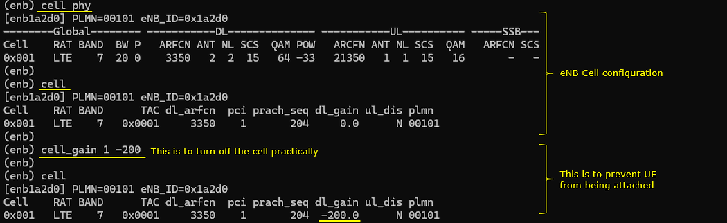
This part shows the runtime LTE cell configuration on the eNB. The key point is that the cell is intentionally made unusable so that the UE does not attach over LTE.
The first section displays the normal LTE cell parameters such as band 7, bandwidth 20 MHz, EARFCN 3350, antenna configuration, and transmission power. This confirms that the cell is configured and running. The second section shows the logical cell configuration including TAC, PCI, PRACH sequence, and PLMN. This is the information that would normally be used by the UE to detect and attach to the cell.
The important part is the cell_gain setting. The command sets the gain to a very low value, effectively reducing the transmit power to a level where the UE cannot detect the cell. After applying this setting, the dl_gain is shown as a very large negative value. This means the downlink signal is practically not transmitted.
As a result, the UE cannot camp on or attach to the LTE cell. This forces the UE to use only the non-3GPP access path.
This setup ensures that the test focuses only on the ePDG tunnel. The LTE radio path is kept running for system stability, but it is effectively disabled from the UE point of view.
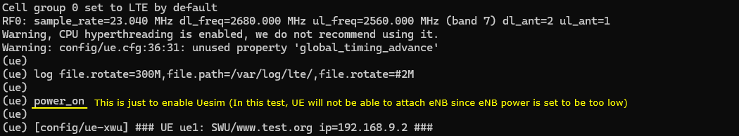
This part shows the startup log of UEsim and confirms that the UE is running. The purpose here is not to attach to LTE, but to bring up the UE so that it can establish the ePDG tunnel.
The system first initializes the LTE configuration. It sets the cell group to LTE and configures the RF parameters such as sample rate, downlink frequency, uplink frequency, and antenna configuration. This step ensures that the UE PHY is ready.
Another warning shows that global_timing_advance is not used. This is expected and does not impact the operation.
The power_on command starts the UE. This enables the UE protocol stack and RF processing. In this test, even though the UE is powered on, it cannot attach to the LTE cell because the eNB transmission power is intentionally reduced.
The final line shows that the UE has created a virtual network interface through the ue-xwu script. It assigns an IP address to the UE, which will be used for traffic over the ePDG tunnel.
At this point, the UE is active and ready. Since LTE attachment is not possible, the UE proceeds with non-3GPP access and establishes the IPSec tunnel toward the ePDG.
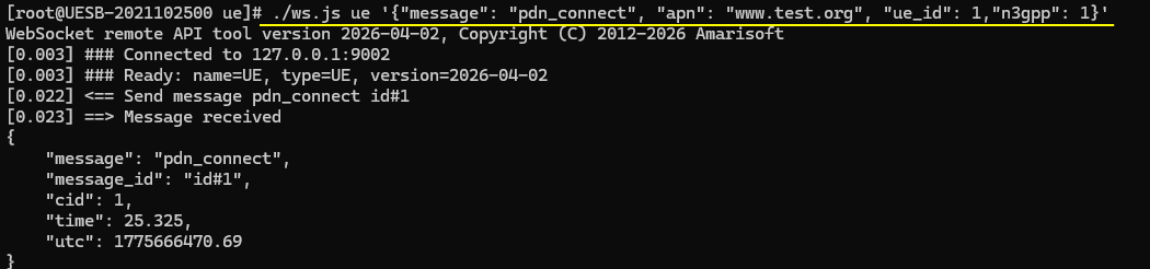
This part shows the command that triggers the UE to start the ePDG connection. This is the key step where the UE initiates the IPSec tunnel setup by sending the remoteAPI command as follows
./ws.js ue '{"message":"pdn_connect","apn":"www.test.org","ue_id":1,"n3gpp":1}'
The ws.js command sends a control message to UEsim through the WebSocket API. The message type is pdn_connect. This tells the UE to establish a PDN connection.
The apn is set to www.test.org. This defines the APN that will be used for the connection. The APN is passed to the core network through the ePDG path.
The ue_id is set to 1, so the command applies to the first UE instance.
The n3gpp is set to 1. This is the critical parameter. It tells the UE to use non-3GPP access, which means the connection will go through ePDG instead of LTE user plane.
When this command is executed, UE sends a request to start PDN connectivity. Since it is non-3GPP access, UE immediately starts the IKEv2 procedure toward the ePDG.
The output shows that the message is sent and acknowledged by UEsim. The cid indicates the context identifier for this PDN session.
At this point, the UE begins the IKE process and proceeds to establish the secure tunnel. This is the starting point of the entire ePDG test flow.
Log Analysis
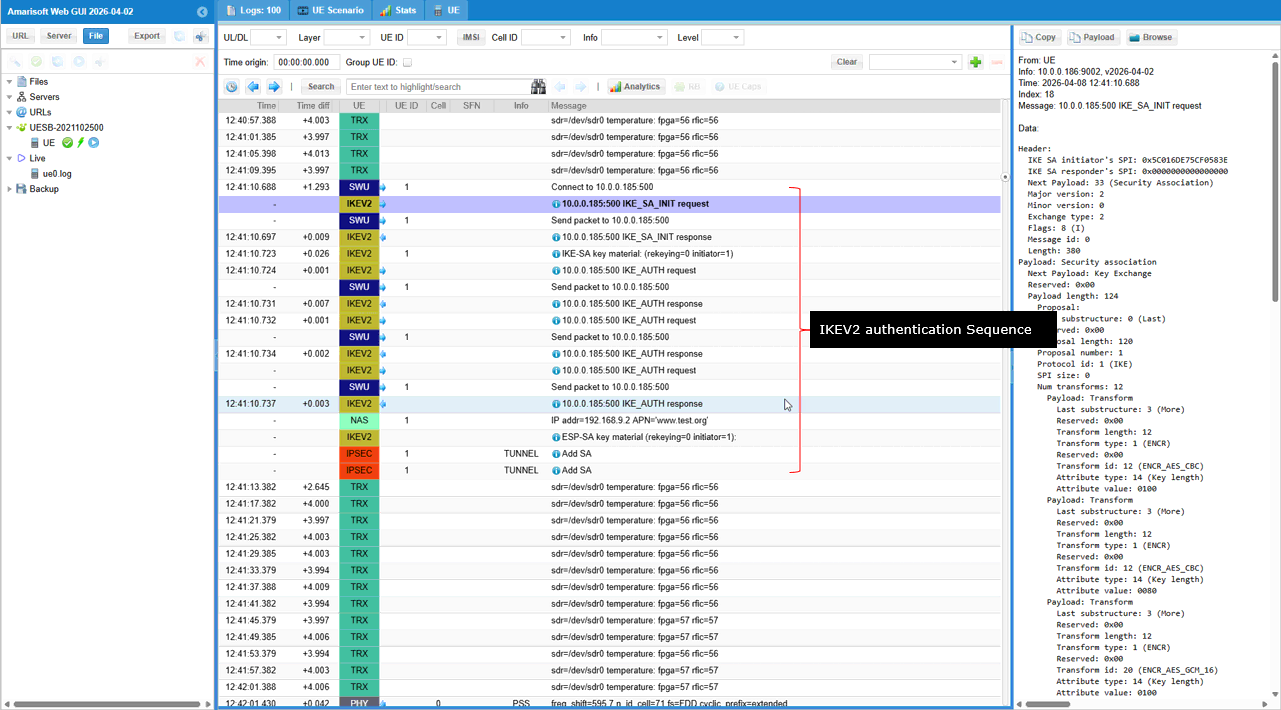
I will not go through the detailed message by message analysis. I will just show the overall sequence of IKEV2 process here. For the detailed message by message analysis, refer to the log analysis of the previous test.
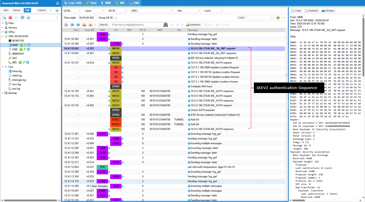
The log lines shown below represents the overall IKEv2 signaling flow between the UE and the ePDG. The purpose is to establish a secure IPSec tunnel for non-3GPP access.
The UE sends IKE_SA_INIT request to the ePDG. This message proposes security parameters such as encryption algorithms, integrity algorithms, and Diffie-Hellman groups.
The ePDG responds with IKE_SA_INIT response. In this step, both sides agree on the security algorithms and perform the initial key exchange.
After this, the UE sends IKE_AUTH request. This message includes authentication information and identity. It also carries parameters needed to establish the IPSec child SA.
During this phase, the UE may trigger interaction with the core network. This includes procedures like Update Location Request and Answer between MME and HSS. This step ensures that the subscriber is authenticated and authorized.
The ePDG processes the authentication and sends IKE_AUTH response. If the authentication is successful, the IPSec tunnel is established.
After successful authentication, IPSec Security Associations are created. These include parameters for encryption and integrity of user plane traffic.
At this point, the secure tunnel is ready. All user data from the UE is encapsulated into ESP packets and sent through this tunnel to the ePDG.
Overall, this sequence shows the standard IKEv2 procedure. First, security capabilities are negotiated. Then authentication is performed. Finally, the IPSec tunnel is created and ready for data transfer.
This is the UEsim side log from the same test.
It shows the same IKEv2 procedure but from the UEsim side. It confirms that the UE is actively initiating and completing the IPSec tunnel setup.
The UE first sends IKE_SA_INIT request to the ePDG. This is the starting point of the IKEv2 procedure. The UE proposes the security algorithms and key exchange parameters. The UE then receives the IKE_SA_INIT response from the ePDG. At this point, both sides agree on the algorithms and complete the initial Diffie-Hellman key exchange. After that, the UE sends the IKE_AUTH request. This message carries the UE identity and authentication information. It also includes parameters to create the IPSec child SA. The UE receives the IKE_AUTH response from the ePDG. This indicates that authentication is successful and the tunnel can be established. During this process, the UE may exchange multiple IKE_AUTH messages. This can happen due to additional authentication steps or configuration details. After successful authentication, the UE creates the ESP Security Associations. This is shown by the ESP-SA key material and Add SA messages. At this point, the IPSec tunnel is fully established. The UE is assigned an IP address, such as 192.168.9.2, which matches the PDN configuration. From this moment, all UE traffic is sent through the IPSec tunnel to the ePDG.
Overall, this log confirms that the UE successfully completes the full IKEv2 sequence and establishes a secure tunnel for non-3GPP access.