SDR Check Up
The purpose of this tutorial is to show how to shift the unwanted DC-offset spike away from the important part of the spectrum (typically the signal band). Because the Analog Devices chipset used in the Amarisoft SDR card is based on a direct-conversion architecture, it inevitably produces a DC-offset spike that cannot be fully eliminated. Although you cannot completely remove this spike, the Amarisoft software (eNB/gNB/UEsim) allows you to move it to a non-critical frequency region so it does not interfere with the main signal.
Table of Contents
Introduction
Direct-conversion radio architectures, commonly employed in modern software-defined radio (SDR) systems such as those powered by Analog Devices chipsets, are renowned for their simplicity and high integration. However, a well-known limitation of this architecture is the presence of a DC-offset spike—an artifact caused by imperfections in the mixer and analog front-end circuitry. This spurious component appears at the center frequency (DC) and can significantly degrade the quality of received or transmitted signals, particularly in applications like LTE or 5G base stations and user equipment emulators where spectral purity is critical. To address this, the Amarisoft SDR platform—including eNB, gNB, and UE simulation software—incorporates configurable mechanisms that allow users to shift the DC-offset spike away from the signal band of interest. By leveraging these features, engineers and researchers can ensure that critical signal regions remain unaffected by hardware-induced artifacts, thus maintaining compliance with spectral emission requirements and improving overall system performance. Understanding the underlying causes, mitigation strategies, and practical configuration steps for managing DC-offset in SDR environments is essential for optimizing wireless system deployments and achieving reliable, high-quality communication links.
-
Technology Context
- The tutorial centers on SDR platforms utilizing direct-conversion (zero-IF) radio architectures, specifically those based on Analog Devices RF chipsets.
- Amarisoft's eNB/gNB/UEsim software stack provides comprehensive tools for 4G/5G radio access network prototyping and testing.
- In direct-conversion receivers, DC-offset arises due to inherent hardware limitations, requiring software-level mitigation to maintain signal integrity.
-
Relevance and Importance
- DC-offset spikes can distort or obscure critical portions of the spectrum, complicating regulatory compliance and impairing system performance.
- The ability to shift the DC-offset out of the important signal band is crucial for developers, researchers, and network engineers working with SDR-based cellular infrastructure.
- This knowledge is particularly important when developing, testing, or deploying custom waveforms, advanced signal processing algorithms, or multi-carrier systems.
-
Learning Outcomes
- Gain a clear understanding of the causes and effects of DC-offset in direct-conversion SDR systems.
- Learn how to leverage Amarisoft software features to shift the DC-offset spike away from the signal band.
- Acquire practical skills for configuring SDR hardware and software to optimize spectral usage and minimize interference.
-
Prerequisite Knowledge
- Familiarity with basic RF concepts, including frequency conversion and baseband processing.
- Understanding of SDR architectures, particularly direct-conversion (zero-IF) designs.
- Experience with Amarisoft software (eNB, gNB, UEsim) and general Linux-based system configuration is recommended.
Summary of the Tutorial
This tutorial provides step-by-step procedures to shift DC Offset spikes for SDR 50 and SDR 100 devices. The tests demonstrate how to utilize configuration parameters, specifically dl_freq in the rf_ports block, to move DC offset artifacts outside of critical channel regions. The methodology is similar for both SDR 50 and SDR 100, but differences in hardware may result in variations in spike behavior.
-
Test 1: Moving away DC Offset Spikes - SDR 50
-
Configuration
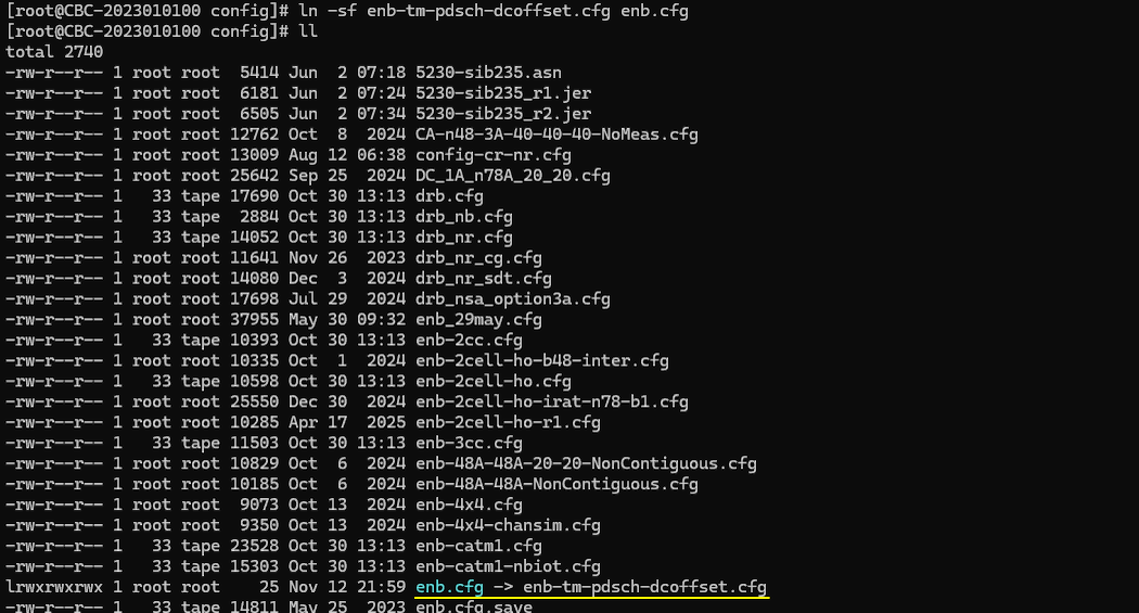
- Use the enb-tm-pdsch-dcoffset.cfg configuration file, which is a modified copy of enb-tm-pdsch.cfg.
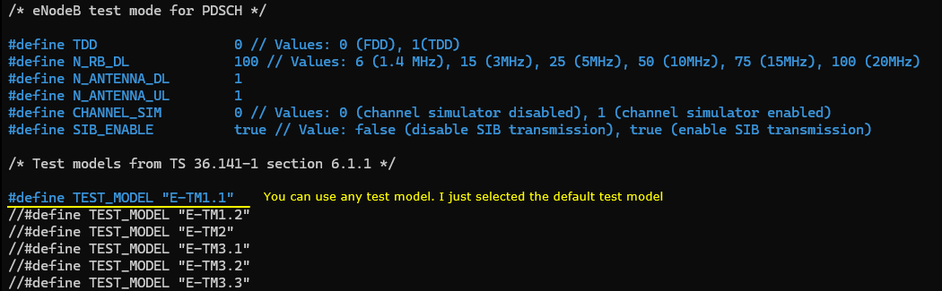
- Select any test mode as needed; the default is sufficient for this test.
-
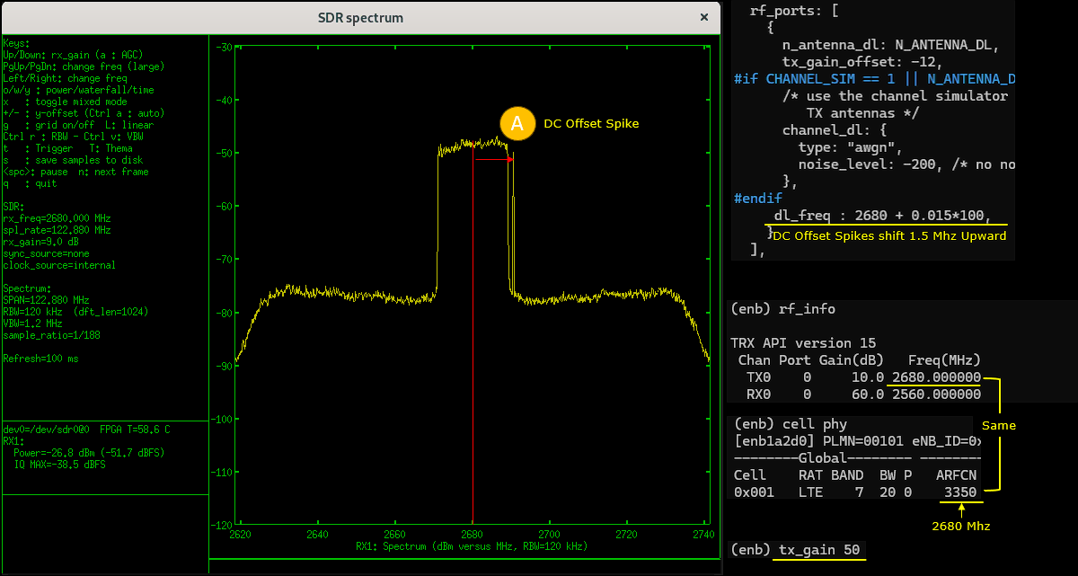
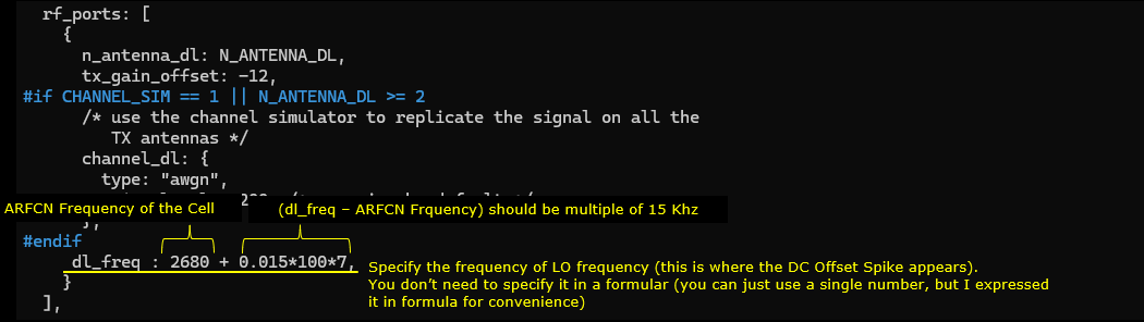
Set the dl_freq parameter in rf_ports to define the LO (Local Oscillator) frequency in MHz. This will determine the position of the DC offset spike:
- If dl_freq matches the cell frequency, the DC offset spike appears at the center of the channel band.
- If dl_freq differs, the spike shifts accordingly.
- The difference between dl_freq and cell frequency must be an integer multiple of 15 kHz (i.e., (dl_freq - Cell Frequency) = N x 0.015 MHz, where N is an integer).
-
Test Execution
- Run the configuration on the Callbox.
- Monitor the TX1 port output using a spectrum analyzer. The sdr_spectrum program on UEsim can be used as an analyzer.
- At high tx_gain, DC offset spikes are typically not visible.
- Reducing tx_gain (low transmit power) reveals DC offset spikes and possibly other artifact peaks, whose characteristics may vary with hardware.
- Adjusting dl_freq shifts only the DC offset spike, not other artifacts.
- For practical operation, set dl_freq to move the DC offset spike outside the critical region (channel band).
-
Configuration
-
Test 2: Moving away DC Offset Spikes - SDR 100
-
Configuration
- Similar to SDR 50, use the enb-tm-pdsch-dcoffset.cfg configuration file.
- Select any test mode, typically the default.
- Set dl_freq in rf_ports to define the LO frequency in MHz, ensuring the frequency difference is a multiple of 15 kHz.
-
Test Execution
- Run the configuration on the Callbox and monitor the TX1 port output with a spectrum analyzer (such as sdr_spectrum on UEsim).
- Reducing tx_gain without adjusting dl_freq will cause DC offset spikes to appear.
- Adjusting dl_freq shifts the DC offset spike, allowing it to be moved out of the channel's critical region.
- Changing the baseband sampling rate does not affect the spike's amplitude or position, but higher rates allow visualization of the spike further from the center frequency.
- The behavior of spike shifting and artifact appearance is consistent with the methodology used for SDR 50.
-
Configuration
The key command relevant to both tests is rf_ports and specifically its dl_freq parameter, which must be set with careful regard to the center frequency and in multiples of 15 kHz for proper operation. The procedures demonstrate practical strategies for minimizing the impact of DC offset artifacts in SDR-based test environments by configuration adjustments and spectrum visualization.
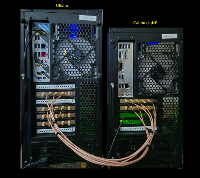
Test Setup
Test setup for this tutorial is as shown below. I would suggest you to connect antenna (or RF cables) to as many sdr cards as possible as per your needs.
Key Command Line
Followings are the list of the important command used in this tutorial.
Test1 : Moving away DC Offset Spikes - SDR 50
This test will show you how to shift DC Offset spikes on SDR50. Both SDR 50 and SDR 100 use TRX chipset from Analog Device, but the chipset model on SDR 100 is more advanced than the one on SDR50. In addition, the board design of SDR 50 and SDR 100 differs. So the characteristics of the DC offset spikes and other parasitic spikes would be a little different between SDR 50 and SDR 100.
Configuration
In this tutorial, I used enb-tm-pdsch-dcoffset.cfg which is copied and modified from enb-tm-pdsch.cfg
In enb-tm-pdsch-dcoffset.cfg , select a specific test mode. It doesn't matter much which test mode you choose, so I just picket the default test mode as it is
The parameter involved in shifting the DC offset spike is dl_freq in rf_ports block. It specifies the absolute frequency in Mhz (not arfcn) which is the frequency of LO (Local Oscillator) of Analog Device TRX chip. If you set this frequency same as the cell frequency, you will see the dc offset spikes at the center of the channel band of the cell. If this is set differently from the cell frequency, you will see the dc offset shifted.
Perform the test
Run the configuration file on Callbox and check the output of TX1 port to a spectrum analyzer. You can use any spectrum analyzer. In this tutorial, I used a sdr card and sdr_spectrum program on UEsim as a spectrum analyzer (
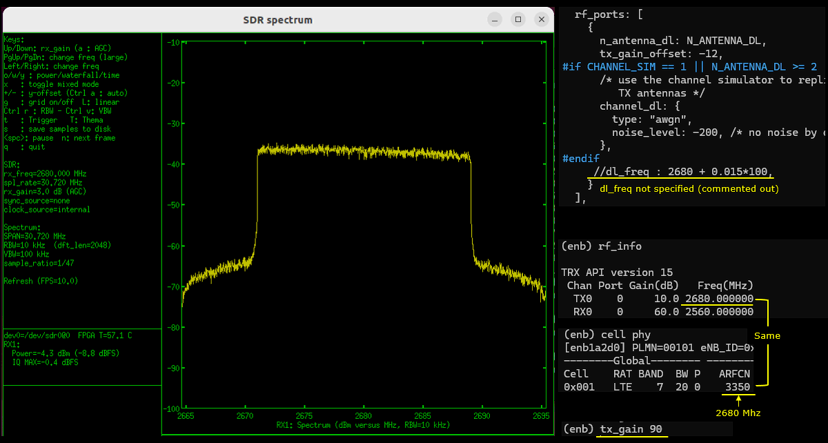
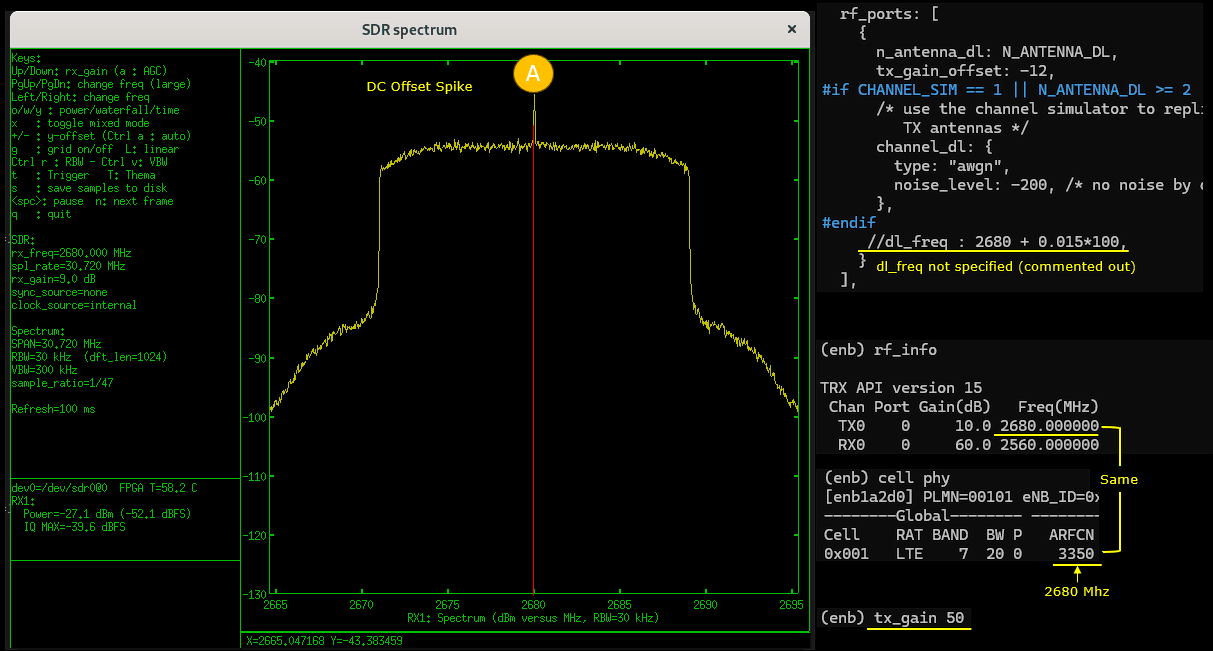
As shown below, usually you wouldn't see any dc offset spikes or any other artifact when tx_gain is high.
If you decrease tx_gain and set the tx power very low, you would see the DC Offset Spikes labeled as (A).
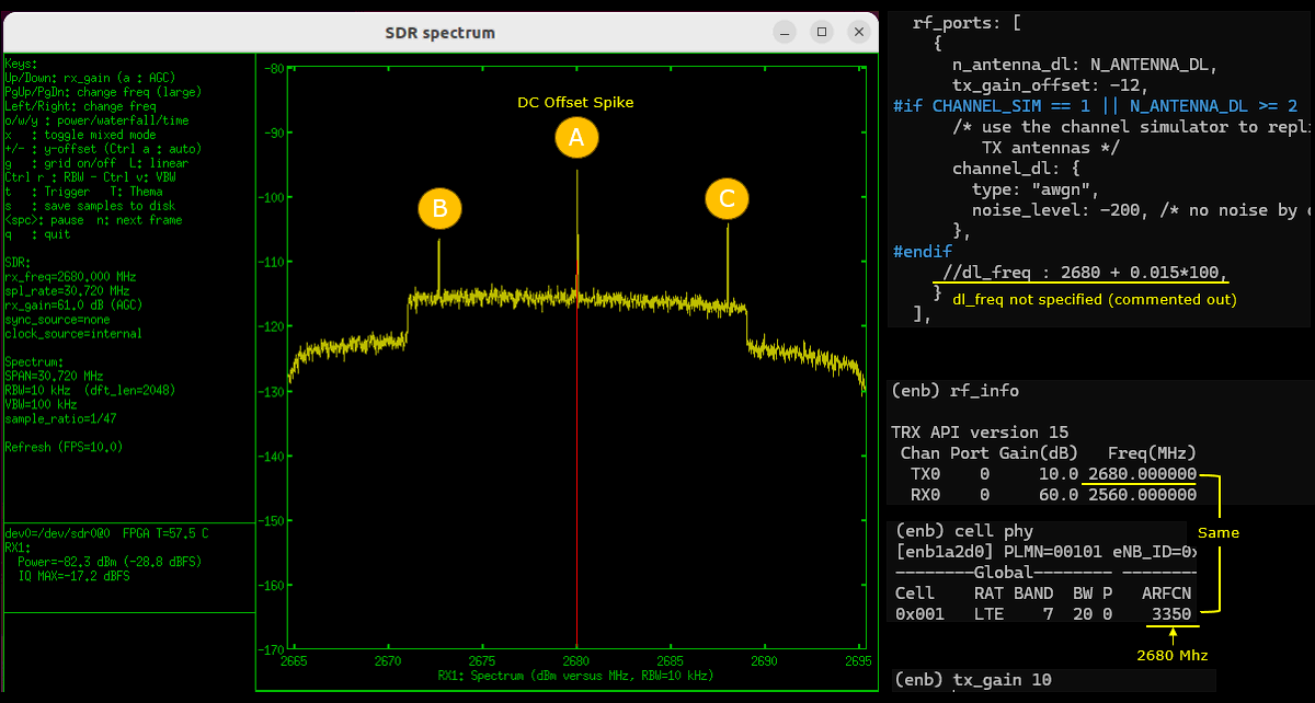
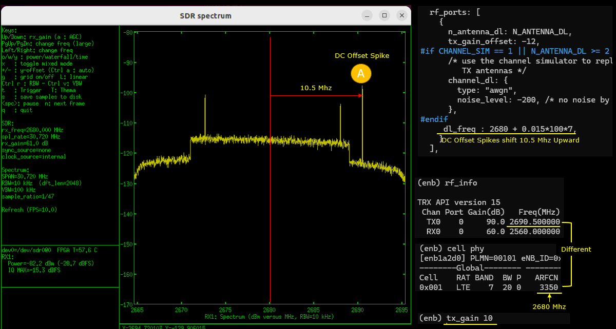
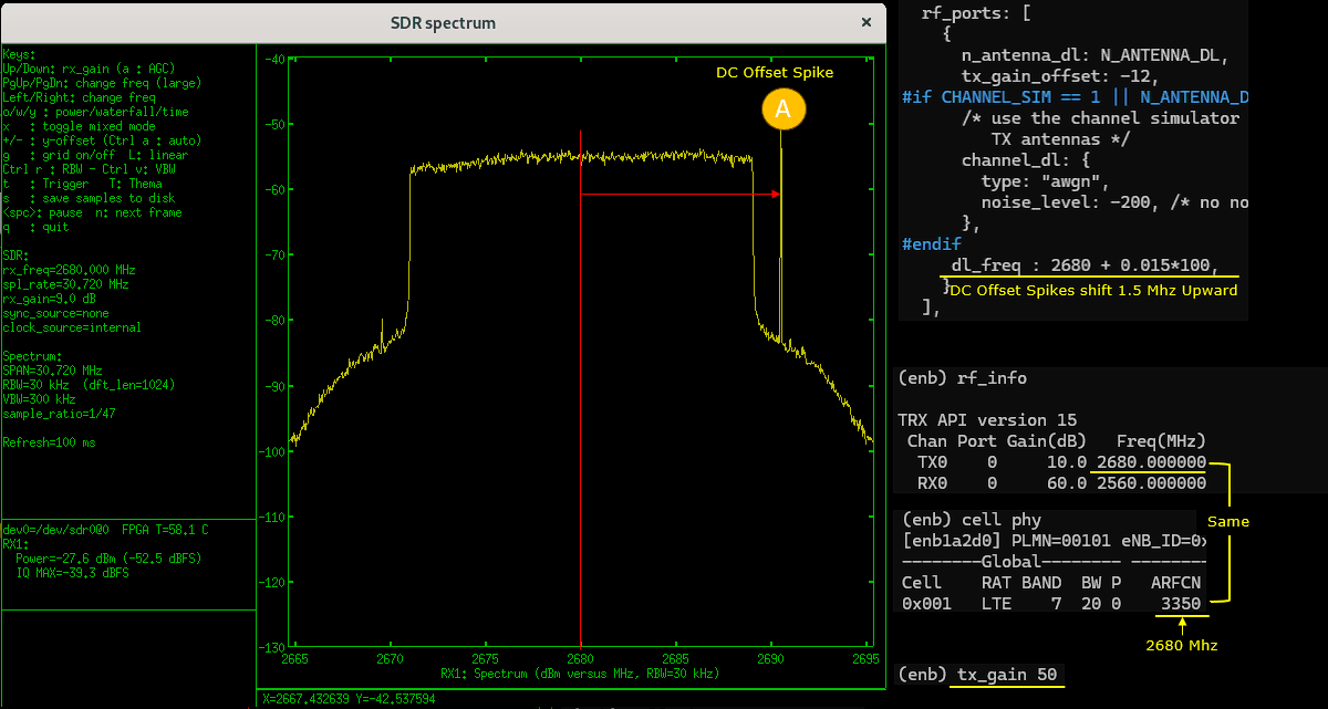
By setting dl_freq in rf_ports, you would notice the DC offset spike gets shifted. (
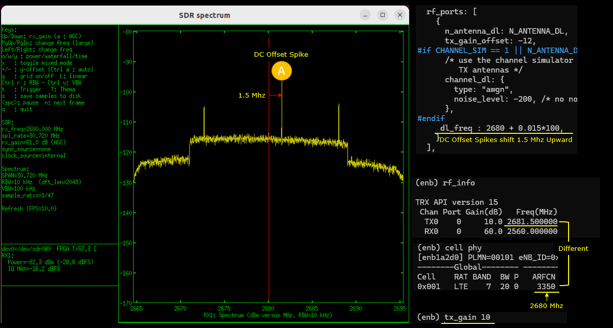
More practical use case of dl_freq is to set it to large enough so that the dc offset spike gets out side of critical region (i.e, channel band region).
Test2 : Moving away DC Offset Spikes - SDR 100
This test will show you how to shift DC Offset spikes on SDR100. Both SDR 50 and SDR 100 use TRX chipset from Analog Device, but the chipset model on SDR 100 is more advanced than the one on SDR50. In addition, the board design of SDR 50 and SDR 100 differs. So the characteristics of the DC offset spikes and other parasitic spikes would be a little different between SDR 50 and SDR 100.
Configuration
In this tutorial, I used enb-tm-pdsch-dcoffset.cfg which is copied and modified from enb-tm-pdsch.cfg
In enb-tm-pdsch-dcoffset.cfg , select a specific test mode. It doesn't matter much which test mode you choose, so I just picket the default test mode as it is
The parameter involved in shifting the DC offset spike is dl_freq in rf_ports block. It specifies the absolute frequency in Mhz (not arfcn) which is the frequency of LO (Local Oscillator) of Analog Device TRX chip. If you set this frequency same as the cell frequency, you will see the dc offset spikes at the center of the channel band of the cell. If this is set differently from the cell frequency, you will see the dc offset shifted.
Perform the test
Run the configuration file on Callbox and check the output of TX1 port to a spectrum analyzer. You can use any spectrum analyzer. In this tutorial, I used a sdr card and sdr_spectrum program on UEsim as a spectrum analyzer (
If you decrease tx_gain without setting dl_freq, you would see the DC Offset Spikes labeled as (A) from a certain tx_gain value..
By setting dl_freq in rf_ports, you would notice the DC offset spike gets shifted. A practical use case of dl_freq is to set it to large enough so that the dc offset spike gets out side of critical region (i.e, channel band region). . (
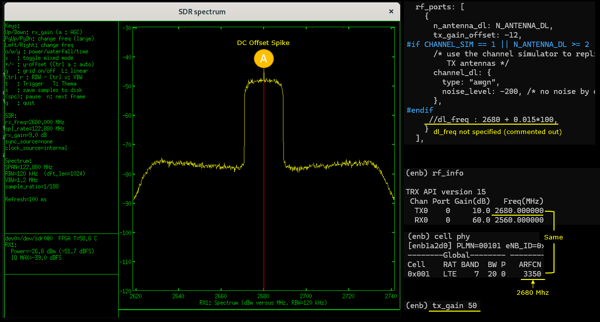
Now let's try the samething as above but with higher baseband sampling rate.
As shown below, the position and amplitue of the spike does not get affected by the sample rate. But if you increase the sample rate, you can visualize the spike farther away from the center frequency.
If you decrease tx_gain without setting dl_freq, you would see the DC Offset Spikes labeled as (A) from a certain tx_gain value..
By setting dl_freq in rf_ports, you would notice the DC offset spike gets shifted. A practical use case of dl_freq is to set it to large enough so that the dc offset spike gets out side of critical region (i.e, channel band region). . (