
SDR API
The purpose of this tutorial is to explain about the architecture and details of sdr_example.c which is located in /root/trx_sdr/api and provide a very simple example of how you can extend the sample code to your own application. The example provided with the installation package would open the possibility of using Amarisoft SDR card as a part of your own software stack.
Table of Contents
Introduction
Software Defined Radio (SDR) represents a transformative approach to radio communications, enabling radio functionalities to be implemented and modified through software rather than traditional hardware components. At the core of SDR technology is the flexibility to process and generate radio signals entirely in the digital domain, allowing for rapid prototyping, easy updates, and support for multiple communication standards on a single hardware platform. The Amarisoft SDR solution is a prominent example in this field, offering a powerful SDR card and an associated software stack that caters to a wide array of wireless communication applications. The sdr_example.c file, located in the /root/trx_sdr/api directory, serves as a reference implementation and starting point for developers aiming to interact with the SDR hardware through a well-defined API. This tutorial delves into the architectural aspects of sdr_example.c, elucidating its structure, initialization routines, interaction patterns with the SDR hardware, and the modular design that allows for extensibility. By understanding the example code and its underlying architecture, developers can efficiently integrate Amarisoft SDR capabilities into their own applications, leveraging the hardware's real-time signal processing features, high throughput capabilities, and seamless software-hardware interfacing. The tutorial further demonstrates a minimal extension, miniGen, to showcase how the foundational concepts in sdr_example.c can be adapted for custom development, underlining SDR's significance as a cornerstone in modern wireless system design and prototyping.
-
Context and Background
- SDR technology abstracts radio signal processing into software, enhancing flexibility and enabling rapid deployment of new protocols.
- Amarisoft SDR cards are widely used in research, prototyping, and production deployments for cellular and wireless communication systems.
- The sdr_example.c file exemplifies direct API interactions with the SDR hardware, providing a template for user-defined radio applications.
-
Relevance and Importance of the Tutorial
- Understanding sdr_example.c is essential for developers seeking to harness the full potential of the Amarisoft SDR platform in custom applications.
- The tutorial bridges the gap between basic SDR card usage and advanced application development tailored to specific wireless needs.
- It highlights best practices for SDR integration, initialization, data flow management, and modular extension within user software stacks.
-
Learning Outcomes
- Comprehend the architectural layout and workflow of sdr_example.c and its role in the SDR software stack.
- Gain insights into SDR API initialization, data handling routines, and event processing mechanisms.
- Understand how to extend the example code to implement bespoke signal generation or processing features, as illustrated with miniGen.
- Develop the capability to design and prototype custom SDR applications using Amarisoft hardware and API interfaces.
-
Prerequisite Knowledge and Skills
- Familiarity with C programming and software development in a Linux environment.
- Basic understanding of digital signal processing (DSP) concepts and radio communication fundamentals.
- Knowledge of how hardware APIs interact with user-space applications for real-time data transfer and control.
- Prior experience with build systems, compilation, and debugging of C code is advantageous for following code modifications and extensions.
Summary of the Tutorial
This tutorial provides a comprehensive overview of using the sdr_example.c application, which demonstrates how to interact with an SDR (Software Defined Radio) device through the libsdr.so library and related APIs. The tutorial details the underlying structure, essential APIs, and a step-by-step methodology for extending the example into a user-specific application, illustrated through the implementation of a simple signal generator called miniGen.
-
Test Setup and Methodology
- The test environment requires an Amarisoft Callbox or UEsim system with at least one SDR card. In the tutorial, two systems are used: the code is executed on the Callbox while the UEsim acts as a spectrum analyzer to validate the transmitted signals.
- The directory structure for the custom application (miniGen) is established under /root/trx_sdr/api. Proper symbolic links are created to reference the necessary library files (libc_wrapper_sdr.so and libsdr.so).
-
General Test Procedure
- Initialize various parameters using default values or user-defined values.
- Start the SDR card using the appropriate API call.
- Set the transmit gain either to a default or user-specified value.
- Create and execute RX and TX threads. These threads typically run infinite loops that continuously read from (RX) and write to (TX) the SDR card.
- On completion of both RX and TX threads, close and release the SDR resources.
-
Application-Specific Procedure: miniGen Signal Generator
-
Code Extension and Structure:
- The sdr_example.c template is copied and modified to create miniGen.c.
- Core functions such as rx_thread_func() and main() are revised.
- New functions are added:
- process_runtime_input()
- process_runtime_user_input()
- reset_sdr()
- GenerateQAM()
-
Runtime Operation:
- Upon execution, the application prints basic information and begins transmitting a signal stream.
- Users can interactively modify signal parameters in real time via command prompts:
- tx_gain: Change or query the current transmit gain.
- tx_freq: Change or query the transmit frequency (Hz).
- tx_bw: Change or query the transmit bandwidth (Hz).
- Parameter changes are reflected immediately in the transmitted signal, which can be validated using a connected spectrum analyzer.
-
Signal Generation Methodology:
- The GenerateQAM() function generates a sequence of IQ data, populating a buffer with complex values representative of a QAM (Quadrature Amplitude Modulation) signal. This buffer is then passed to the transmit buffer of the SDR port for transmission.
- Parameters to GenerateQAM() include:
- Pointer to the buffer (buf) for complex numbers
- Buffer length (len)
- QAM modulation order (M)
- The function iterates over the buffer, generating random x and y coordinates for each symbol, ensuring placement on a QAM constellation grid.
-
Code Extension and Structure:
-
Core APIs Used in Procedures
- Opening and initializing the SDR device: msdr_open()
- Setting and releasing start parameters: msdr_set_default_start_params(), msdr_release_start_params()
- Starting and stopping the SDR: msdr_start(), msdr_stop()
- Gain configuration and querying: msdr_set_tx_gain(), msdr_get_tx_gain(), msdr_set_rx_gain(), msdr_get_rx_gain()
-
Key Notes on Application Development
- Modification and extension of rx_thread_func() and tx_thread_func() are crucial for tailoring the application to specific use cases.
- The RX thread is essential for timing and synchronization, even for TX-only applications.
In summary, the tutorial outlines a clear methodology for developing and testing custom SDR applications using libsdr.so, detailing both the setup and operational steps, while emphasizing the importance of proper application structure and runtime parameter control.
Where to Get ?
The sdr_example.c is provided with installation package and you can find the code and required libraries at /root/trx_sdr/api.
The directory holds sdr_example.c together with everything you need to build it. libsdr.h is the header that declares the API, and libsdr.so is the library itself. libsdr.so and libc_wrapper_sdr.so are not real files here. They are symbolic links pointing to ../libsdr.so and ../libc_wrapper_sdr.so, one level up in /root/trx_sdr.
The Makefile in the same directory builds sdr_example.c against those links. cpri_hook.c and Makefile.cpri_hook are for a different purpose and are not used in this tutorial. Remember the two symbolic links, because they are the part you have to recreate when you build your own code in another directory.

Underlying Structure
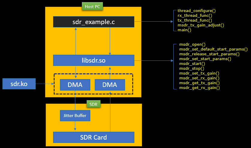
sdr_example.c is running on top of sdr device driver and libsdr.so library. The overall structure of sdr_example.c and underlying components are illustrated below. libsdr.so is communicating with sdr device driver and provide various API for user program (e.g, sdr_example.c in this case).
You can check out the entire list of the API functions provided by libsdr.so from libsdr.h file located in /root/trx_sdr/api. Some of the API functions that are most commonly used by user program are those functions starting with msdr :
- msdr_open()
- msdr_set_default_start_params()
- msdr_release_start_params()
- msdr_start()
- msdr_stop()
- msdr_set_tx_gain()
- msdr_set_rx_gain()
- msdr_get_tx_gain()
- msdr_get_rx_gain()
The functions of user program would vary widely depending on the purpose (application) of the program, but the template code (sdr_example.c) implements several important functions as below. Whatever application you would create, it is highly likely that these functions will be used in your own application as well.
- thread_configure()
- rx_thread_func()
- rx_thread_func()
- msdr_tx_gain_adjust()
The stack is represented by two boxes. The upper box is the Host PC and the lower box is the SDR. On the host side sdr_example.c sits on top of libsdr.so, and libsdr.so owns the DMA channels that move samples in both directions. The kernel module sdr.ko is drawn outside the host box and attached to the DMA pair, because the driver is what makes those DMA channels visible to the library.
The arrows between the boxes go both ways. One direction carries the RX samples up to sdr_example.c and the other carries the TX samples down to the SDR card. On the SDR side the samples pass through a jitter buffer before they reach the SDR card, so a small timing variation on the host does not break the transmission.
The two lists on the right are split by which layer owns them. The upper list is what sdr_example.c itself implements : thread_configure(), rx_thread_func(), tx_thread_func(), msdr_tx_gain_adjust() and main(). The lower list is what libsdr.so exports, and every name in it starts with msdr_. That split is worth keeping in mind. You rewrite the upper list for your own application and you call the lower list as it is.
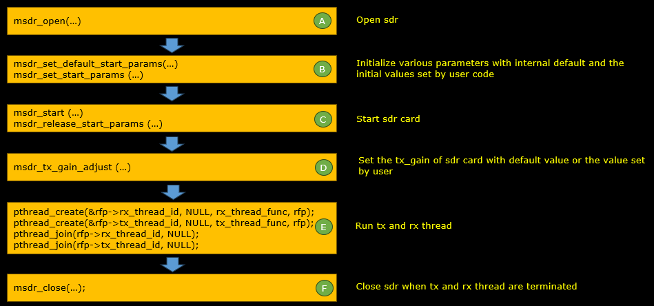
Overall flow of sdr_example.c is illustrated below. I think you would follow this basic sequence in your own application as well.
- i) Initialize various parameters with internal default and the initial values set by your own code
- ii) Start sdr card
- iii) Set the tx_gain of sdr_card with default value or the value set by your own code
- iv) create and execute rx_thread and tx_thread. This part is the core of the user application. Usually there is infinate loop within these function that are continuously reading and writing data from/to sdr card.
- v) When the both rx_thread and tx_thread finished, close sdr
Each of the six steps is labelled A to F and maps to one or two API calls. A is msdr_open(). B is msdr_set_default_start_params() followed by msdr_set_start_params(). C is msdr_start() with msdr_release_start_params(). D is msdr_tx_gain_adjust(). E is the four pthread calls that create and join the rx and tx threads, and F is msdr_close().
Note that step B uses two calls, not one. msdr_set_default_start_params() fills the parameter structure with the internal defaults, and msdr_set_start_params() pushes the structure down to the card after your own code has overwritten the fields it cares about. This is also the pair that reset_sdr() reuses later when the user changes frequency or bandwidth at runtime.
Step E is where the application actually lives. The two pthread_join() calls in the same box are what makes step F safe. main() does not reach msdr_close() until both threads have returned.
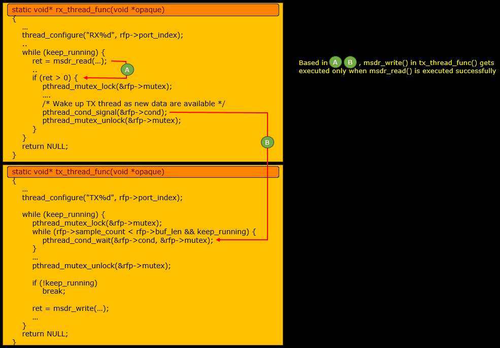
The most important component of sdr_example are the two functions : rx_thread_func and tx_thread_func. There are some dependancies between these two function as illustrated below. As show in this illustration, the rx_thread is essential because it gives the timing information from the hardware. Even for a pure TX application (e.g. signal generator) you would need to have this thread to trigger the tx thread as needed..
The dependency is marked at two points, A and B. A is the line ret = msdr_read(...) in rx_thread_func() and the if (ret > 0) test just below it. B is the pthread_cond_signal(&rfp->cond) that runs inside that if block. The arrow from B goes down into tx_thread_func() and lands on the pthread_cond_wait(&rfp->cond, &rfp->mutex) call. Because of A and B, msdr_write() in tx_thread_func() gets executed only when msdr_read() has succeeded.
So the tx thread is not free running. It takes the mutex, then blocks in pthread_cond_wait() while rfp->sample_count is smaller than rfp->buf_len. The rx thread is what releases it, and the rx thread is driven by the hardware through msdr_read(). That is how the transmission stays aligned with the card timing without the application keeping a clock of its own.
Both loops are guarded by the same keep_running flag. tx_thread_func() tests it a second time after the mutex is unlocked. That way it breaks out instead of writing one more buffer during shutdown.
Basic APIs
There are a long list of APIs supported by libsdr.so (declared in /root/trx_sdr/api/libsdr.h). But the list of the most important APIs (especially for this tutorial) can be listed as below.
The first group is the life cycle of the device. msdr_open() takes an argument string and returns a MultiSDRState pointer, and that pointer is the handle you pass to every other call. msdr_set_default_start_params() fills an SDRStartParams structure and also fixes tx_count, rx_count and port_count. msdr_set_start_params() sends the structure to the card, msdr_start() brings it up, and msdr_stop() brings it down.
The second group is the gain control. msdr_set_tx_gain() and msdr_set_rx_gain() take a channel index and a gain in dB, and the two msdr_get_ calls return the current value as a double. These are the only settings that can be changed while the card is running. Everything carried in SDRStartParams needs a stop and a restart, which is what reset_sdr() does later in this tutorial.
|
MultiSDRState *msdr_open(const char *args); void msdr_set_default_start_params(MultiSDRState *s, SDRStartParams *p, size_t p_size,int tx_count, int rx_count, int port_count); void msdr_release_start_params(MultiSDRState *p, size_t p_size); int msdr_set_start_params(MultiSDRState *s, const SDRStartParams *p, size_t p_size); int msdr_start(MultiSDRState *s); int msdr_stop(MultiSDRState *s);
int msdr_set_tx_gain(MultiSDRState *s, int channel, double gain); int msdr_set_rx_gain(MultiSDRState *s, int channel, double gain); double msdr_get_tx_gain(MultiSDRState *s, int channel); double msdr_get_rx_gain(MultiSDRState *s, int channel); |
Example 1 : Simple Signal Generator
Just as an example of showing how to modify/extend sdr_example.c for user specific application, I will write a code for very simple signal generator. It just generate continuous stream of QAM signal and transmit it to TX port of SDR card. For the simplicity of the description, I will call this application as miniGen.
Test Setup
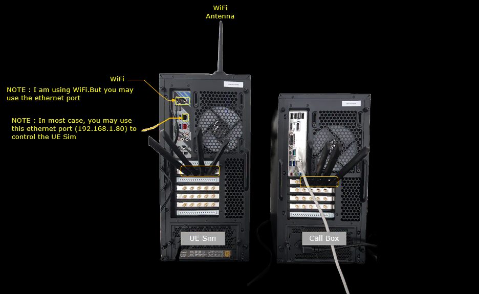
To test the code, the only requirement would be to have Amarisoft Callbox or UEsim with at least one SDR card. In this tutorial, I used two systems (Callbox and UEsim). I am running my code on callbox and using UEsim as a spectrum analyzer to validate the output of my application.
The two boxes are seen from the rear. The UE Sim is on the left and the Call Box is on the right, and one SDR card is marked on each of them. The RF cable runs from the TX1 port of the callbox SDR card to the RX port of the UEsim SDR card. That single cable is the whole RF path of this test.
The rest of the marking is about how you reach the UE Sim. I am using WiFi through the antenna on top, but you may use the ethernet port instead. In most cases you would use the ethernet port at 192.168.1.80 to control the UE Sim.
Code Structure
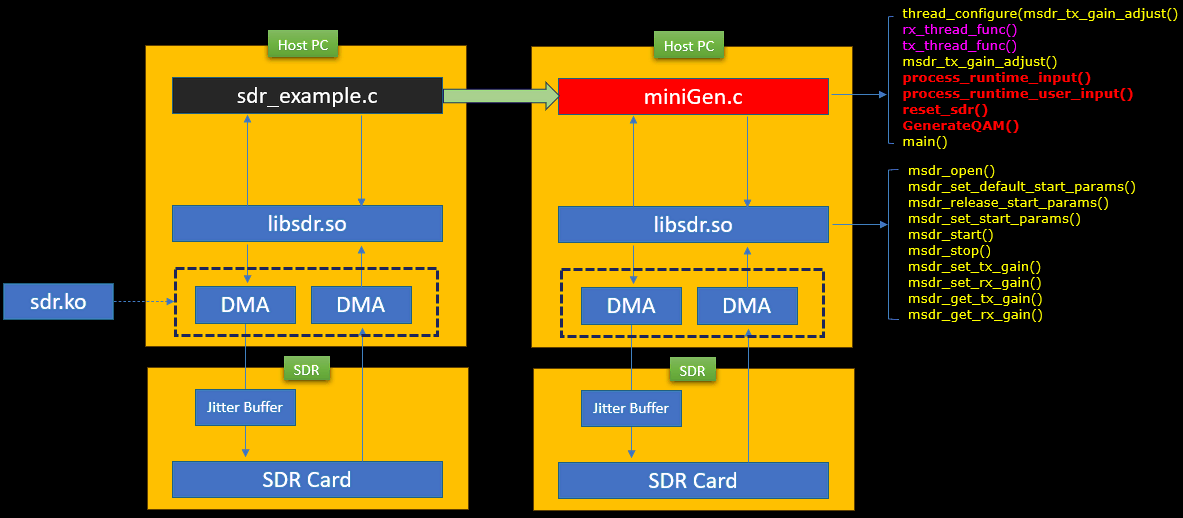
The way I extend the sdr_example.c to my own application (miniGen.c) is illustrated as below. Basically I just copied sdr_example.c to miniGen.c and revise the existing functions and add a couple of new functions.
- Functions revised from the sdr_example.c
- rx_thread_func()
- rx_thread_func()
- main()
- Functions newly added
- process_runtime_input()
- process_runtime_user_input()
- reset_sdr()
- GenerateQAM()
The same stack is drawn twice, with sdr_example.c on the left and miniGen.c on the right. Only the top block changes. libsdr.so, the DMA pair, sdr.ko, the jitter buffer and the SDR card are identical on both sides, so nothing below the application had to be touched to get miniGen running.
The function list on the right is colour coded. thread_configure(), msdr_tx_gain_adjust() and main() are the ones carried over. rx_thread_func() and tx_thread_func() are marked as revised, and process_runtime_input(), process_runtime_user_input(), reset_sdr() and GenerateQAM() are marked as new. The msdr_ list below it is unchanged, since miniGen calls exactly the same library entry points.
Directory and Files
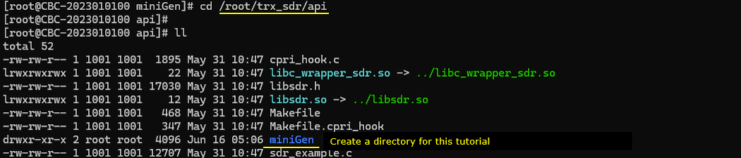
For this tutorial, I created a directory named miniGen under /root/trx_sdr/api. (
The miniGen directory now sits in /root/trx_sdr/api next to sdr_example.c. It is the only entry added, and everything else in the listing is the original content of the api directory.
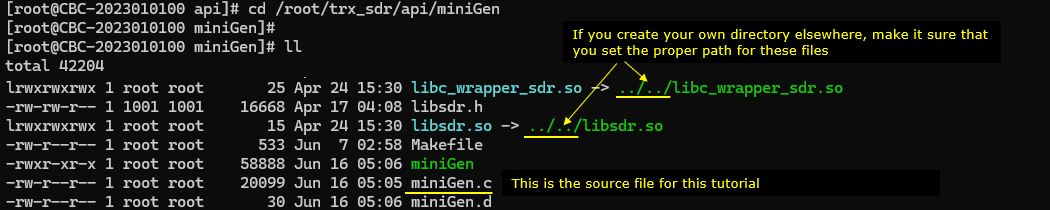
Since I created a new directory, I changed the symbolic links to properly points to the location of the library file (libc_wrapper_sdr.so and libsdr.so)
Inside /root/trx_sdr/api/miniGen the two links now point to ../../libc_wrapper_sdr.so and ../../libsdr.so. They have two levels of .. instead of one, because miniGen is one directory deeper than the api directory where the original links live. If you create your own directory somewhere else, this is the part you have to fix for your own path.
The rest of the directory is the working set for this tutorial. miniGen.c is the source file, miniGen is the built binary, and libsdr.h is the copy of the header. The Makefile is the one copied from the api directory.
How it works
This is how my sample code (miniGen.c) works.
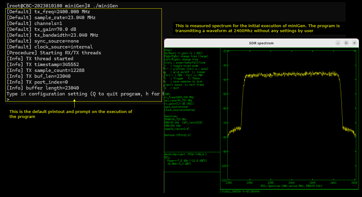
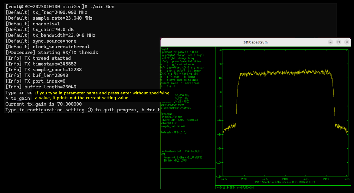
When you run the code, you will see a bunch of basic informations printed out. At this point, a stream of the signal start being transmitted as shown in the spectrum (
The lines marked [Default] are the values miniGen starts with when you give it no command line option. tx_freq is 2400.000 MHz, sample_rate is 23.040 MHz, channels is 1, tx_gain is 70.0 dB and tx_bandwidth is 23.040 MHz. sync_source is none and clock_source is internal, so the card runs on its own clock and is not locked to anything external.
The [Procedure] and [Info] lines come after that. They report that the RX and TX threads have started. They also print the values the tx thread is working with : timestamp 345552, sample_count 12288, buf_len 23040 and port_index 0. The buffer length of 23040 is the number of samples msdr_write() sends in one go, and it follows the 23.04 MHz sample rate. The prompt at the bottom is printed by process_runtime_user_input() and it is where you type the commands.
The transmission is already running at this point. The spectrum is taken on the UEsim card with rx_freq 2400.000 MHz and a span of 30.720 MHz. It shows a flat block of about 23 MHz centred on 2400 MHz. That width is the tx_bandwidth default. The measured RX1 power is -7.6 dBm.
Now you can change the parameters of the signal generator by typing in command at the prompt. The parameters you can change in this example code are
- tx_gain : change TX gain or retrieve the current TX gain
- tx_freq : change TX frequency (in Hz) or retrieve the current TX frequency (in Hz)
- tx_bw : change TX Bandwidth (in Hz) or retrieve the current TX Bandwidth (in Hz)
First, let's change tx_gain. If you just type in 'tx_gain' and hit enter without specifying any specific value, it prints out the tx_gain which is currently set.
Typing tx_gain alone at the prompt returns Current tx_gain is 70.000000, which matches the [Default] tx_gain line printed at startup. The value is read back from the card with msdr_get_tx_gain(), not from a variable kept in the program.
The prompt comes back straight away and the spectrum does not move. A query does not touch the card settings, so the transmission carries on untouched while you read the value.
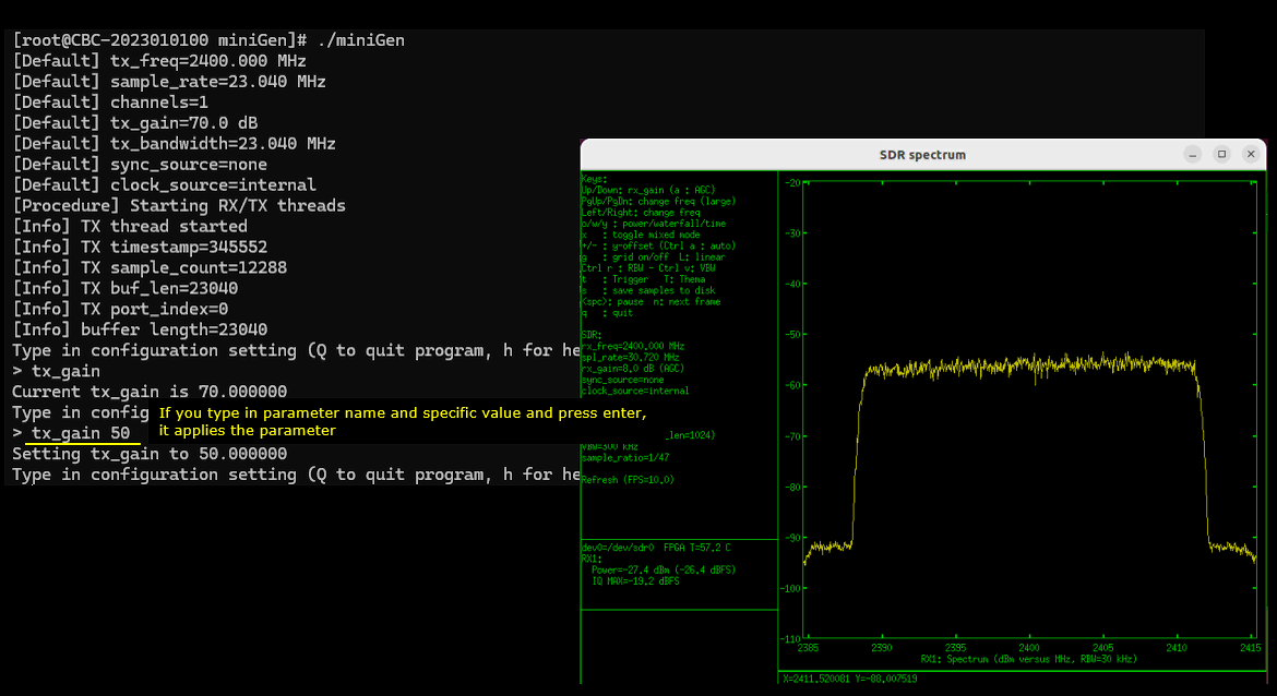
Now let's try setting a specific value for tx_gain by typing in the command and value. Then the specified value is applied and you can confirm that result of the execution on spectrum analyzer.
Here the command is tx_gain 50 and the program answers Setting tx_gain to 50.000000. The gain went down by 20 dB from the 70 dB default.
The spectrum follows. The flat block that sat near -37 dBm now sits near -57 dBm, and the RX1 power reading drops from -7.6 dBm to -27.4 dBm. That is the same 20 dB, so the change reached the card as it was typed. The shape and the width of the signal are unchanged, because only the gain was touched.
This one is handled by msdr_set_tx_gain() and it takes effect immediately. The transmission is never interrupted, which is not the case for the two commands that follow.
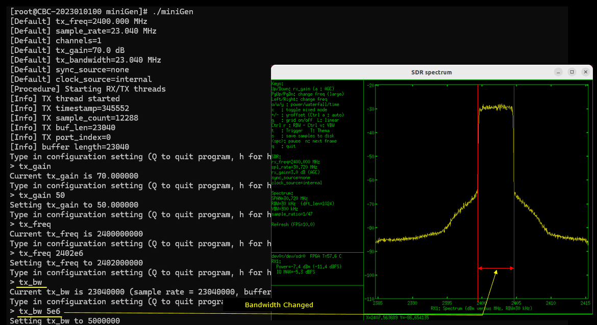
In the same way, you can use the tx_freq command. Just running tx_freq(TX Center Frequency) without a specified value to get the current setting and with a specified value to change tx_freq value.
tx_freq on its own returns Current tx_freq is 2400000000, and tx_freq 2402e6 answers Setting tx_freq to 2402000000. The value is entered in Hz and the exponent form is accepted, so 2402e6 is the same as typing 2402000000.
The centre frequency of the transmitted block moves up by 2 MHz on the spectrum. The analyzer itself was left at rx_freq 2400.000 MHz, so the block is now off centre in the window rather than sitting in the middle of it. Only the signal moved.
Unlike tx_gain, this one cannot be applied on a running card. The frequency lives in SDRStartParams, so reset_sdr() stops the card, pushes the new parameters and starts it again. The transmission is briefly paused while that happens.

In the same way, you can use the tx_bw command. Just running tx_bw (TX bandwidth) without a specified value to get the current setting and with a specified value to change tx_bw value.
tx_bw prints more than the other two. Current tx_bw is 23040000 comes back together with the sample rate and the buffer length, because all three move as a set. Then tx_bw 5e6 answers Setting tx_bw to 5000000.
The occupied bandwidth on the spectrum narrows from about 23 MHz to about 5 MHz, and the marked span sits around the 2402 MHz centre set by the previous command. The peak level rises at the same time, since the same transmit power is now packed into a fifth of the bandwidth.
The skirts on both sides of the block are wider than they were. The IQ data from GenerateQAM() is not shaped or normalized, and that is what you see here. This is also the reason for the note under GenerateQAM about normalizing the samples to +/- 1 before you use the function for anything real.
Code Details
Now let's look a little bit further into the source of the application. You can get the entire code here. Here I will just take a look at some important highlights only and will not go through the entire code line by line.
GenerateQAM
The functionality of this function is simple. It generate a sequence of IQ data and store the sequence into a specified buffer. In this example application, the generated sequence will be stored to a specific TX buffer of sdr RF port(e.g, rf_ports[0].tx_buf[0]) which will eventually passed to msdr_write.
The function takes three arguments. buf is the Complex array to fill, len is how many symbols to write, and M is the modulation order. M is assumed to be a perfect square, and sqrtM is taken with sqrt(M) at the top of the function. main() calls it with M set to 256, so sqrtM is 16.
The body is one loop over len. For each symbol it draws rand() % sqrtM, multiplies by 2 and subtracts sqrtM - 1. This puts the value on the odd integer grid from -sqrtM + 1 to sqrtM - 1. x goes into buf[i].re and y into buf[i].im, and the two are drawn independently. There is no filtering and no scaling, so the buffer is a raw sequence of constellation points.
If you want a different modulation, change the M passed from main(). M set to 4 gives QPSK and M set to 16 gives 16QAM. Keep in mind the range the loop produces. With M at 256 the values reach +/- 15, and the note below says what has to be done about that before the data is fit for the card.
|
int GenerateQAM(Complex *buf, int len, int M) { int i; float x, y; int sqrtM = sqrt(M); // Assuming M is a perfect square for (i = 0; i < len; i++) { x = ((rand() % sqrtM) * 2 - sqrtM + 1); // Random number between -sqrt(M) and sqrt(M) y = ((rand() % sqrtM) * 2 - sqrtM + 1); // Random number between -sqrt(M) and sqrt(M) buf[i].re = x; buf[i].im = y; } return 0; } |
process_runtime_user_input
As easily guessed from the name of the function, this function is to process the input command from user. In this example application, a few threads (tx thread, rx thread) are always running in the background. So this function should be also run as a thread to process the customer input while the signal transmission is ongoing in the background.
Two functions are listed below and they split the work. process_runtime_user_input() is the loop that reads the line, and process_runtime_input() is the parser that acts on it.
The loop runs while keep_running is set. It prints the prompt, reads a line with fgets() into a 256 byte buffer, and strips the trailing newline with strcspn(). Typing q or Q clears keep_running and breaks out, and that is what ends the whole program. An empty line is dropped by the if (input[0]) test. Anything else goes to process_runtime_input().
The parser splits the line with strtok(). The first token is the command and the second is the optional value. It then compares the command against tx_freq, tx_gain and tx_bw, and each of the three branches checks whether optarg is NULL. NULL means print the current setting and a value means apply it. That is the behaviour you saw at the prompt earlier. To add a command of your own, add one more else if branch here with the same two way test.
|
/** * This function continuously processes user input from the command line for runtime configuration of the application. * It prompts the user for configuration settings, processes commands, and allows the user to quit the program. * * The function operates in a loop, reading input from the standard input. It supports two special commands: * - 'Q' or 'q': Quits the program by breaking the loop and setting a flag to stop further processing. * - 'h': Typically would display help information, though the handling for 'h' is expected to be within the `process_runtime_input` function. * * Any other input is passed to the `process_runtime_input` function for further processing, assuming the input is not just a newline. */ void *process_runtime_user_input() { char input[256];
while (keep_running) { printf("Type in configuration setting (Q to quit program, h for help) \n> "); fgets(input, sizeof(input), stdin);
// Remove trailing newline input[strcspn(input, "\n")] = 0; // Check if the user entered 'q' or 'Q' if (strcmp(input, "q") == 0 || strcmp(input, "Q") == 0) { keep_running = 0; break; } else { if (input[0]) process_runtime_input(input); }
} return NULL; }
/** * Parses the input string to extract the command and its optional argument. * Supports commands for displaying help, setting transmission frequency, gain, * bandwidth, and other operational parameters. * * Commands: * - h or help: Displays available commands and their usage. * - tx_freq <frequency>: Sets the transmit frequency in Hz. Displays current frequency if no value is provided. * - tx_gain <gain>: Sets the transmit gain. Displays current gain if no value is provided. * - tx_bw <bandwidth>: Sets the transmit bandwidth in Hz. Displays current bandwidth, sample rate, and buffer length if no value is provided. * @param input The raw input string containing a command and optionally its value. */ void process_runtime_input(char* input) { char* command = strtok(input, " "); char* optarg = strtok(NULL, " ");
if (strcmp(command, "tx_freq") == 0) { if (optarg != NULL) { // Set tx_freq } else { // Print current tx_freq } } else if (strcmp(command, "tx_gain") == 0) { if (optarg != NULL) { // Set tx_gain } else { // Print current tx_gain } } else if (strcmp(command, "tx_bw") == 0) { if (optarg != NULL) { // Set tx_bw } else { // Print current tx_bw } } else { // Handle unknown command } } |
reset_sdr
This functions is to reset sdr card. In current implementation of sdr library, the only parameter/configuration that can be changed while sdr is running is tx/rx gain change. All other configurations (e.g, frequency, bandwidth, sample rate etc) requires resetting the sdr. That's why I wrote this function to allow users to change frequency, bandwidth on the fly.
The function is short and the order of the steps is what matters. It sets paused to 1 first, then waits 100 ms with usleep(100000) so the rx and tx threads reach a safe point before the card goes down. Only then does it call msdr_stop().
The restart is msdr_set_start_params() followed by msdr_start(), the same pair used in main(). Both are checked and both call exit(1) on a negative return, so a bad parameter value stops the program instead of leaving the card half configured. The last line clears paused back to 0 and the threads resume.
Note the commented out msdr_release_start_params() between the two calls. It is left out on purpose here, because the same params structure is used again on the next reset. Releasing it would free the structure that the next frequency or bandwidth change still needs.
|
/** * Resets the software-defined radio (SDR) to a known state. * * This function performs a series of operations to safely reset the SDR. It ensures that the SDR is stopped, * reconfigured with new parameters, and restarted. The process involves: * * 1. Pausing any ongoing operations by setting a flag. * 2. Waiting for a brief period to ensure all operations have been halted. * 3. Stopping the SDR to ensure it's in a known state before reconfiguration. * 4. Attempting to set new start parameters for the SDR. If this fails, an error is reported and the program exits. * 5. Restarting the SDR with the new parameters. If this fails, an error is reported and the program exits. * 6. Resuming operations by clearing the pause flag, indicating the SDR is ready for use. * */ void reset_sdr() { paused = 1; usleep(100000); msdr_stop(s); /* Start */ ret = msdr_set_start_params(s, params, sizeof(*params)); if (ret < 0) { fprintf(stderr, "msdr_set_start_params: invalid SDR parameters\n"); exit(1); }
ret = msdr_start(s); //msdr_release_start_params(params, sizeof(*params)); <-- Commented out this because the same parameter structure is used again. if (ret < 0) { fprintf(stderr, "msdr_start: error\n"); exit(1); } paused = 0; } |
tx_thread_func
This function is the most important part of this example application (i.e, signal generator) but there are almost no change from the sdr_example.c. I just put a bunch of printf() to print out some basic information. However it is important to clearly understand what this function does. This function will be run as a thread in main()
The argument is a void pointer that is really an RFPort pointer. That structure carries the buffers, the mutex, the condition variable and the timestamp for one RF port. The first call in the body is thread_configure("TX%d", rfp->port_index), which names the thread after the port it serves.
Then the loop runs while keep_running is set. It locks rfp->mutex, and waits on pthread_cond_wait() for as long as rfp->sample_count is below rfp->buf_len. The rx thread is what signals that condition. After the mutex is unlocked there is a second keep_running test, so a shutdown breaks the loop before another write is attempted.
The write itself is msdr_write(rfp->msdr_state, rfp->tx_timestamp, rfp->tx_buf, rfp->buf_len, rfp->port_index, &mdw). The data it sends is whatever GenerateQAM() left in rfp->tx_buf. The timestamp is advanced by the number of samples written, which is how the next buffer lands where the card expects it. If you write your own transmitter, this is the function to change, and the buffer you fill is the one named here.
|
/** * The transmission thread function for a sdr. * * This function is designed to run in a separate thread and handles the transmission of data through an SDR. It takes a pointer to an RFPort structure as its argument, which contains all the necessary * information and buffers for transmission. * * The function performs the following operations: * - Initializes the transmission thread and prints initial transmission parameters. * - Enters a loop that continues as long as a global `keep_running` flag is set. * Inside the loop, it: * - Locks the associated mutex to safely access shared resources. * - Waits for the condition variable if the sample count is less than the buffer length, indicating that there isn't enough data to transmit. * - Adjusts the sample count and transmission timestamp after waking up. * - Unlocks the mutex. * - Checks if the `keep_running` flag is still set; if not, exits the loop. * - Calls `msdr_write` to transmit data. If successful, adjusts the transmission timestamp based on the number of samples written. * * The loop exits either when `keep_running` is cleared(keep_running is set to 0 when you press Ctrl+C or 'q'/'Q'. */ static void* tx_thread_func(void *opaque) { ... thread_configure("TX%d", rfp->port_index);
// Print basic information
while (keep_running) { pthread_mutex_lock(&rfp->mutex); while (rfp->sample_count < rfp->buf_len && keep_running) { pthread_cond_wait(&rfp->cond, &rfp->mutex); } ... pthread_mutex_unlock(&rfp->mutex);
if (!keep_running) break;
// Write the data stored in rfp->tx_buf to sdr card to transmit. the data of rfp->tx_buf is prepared in GenerateQAM function. ret = msdr_write(rfp->msdr_state, rfp->tx_timestamp, (const void**)rfp->tx_buf, rfp->buf_len, rfp->port_index, &mdw); ... } return NULL; } |
main
What you need to note and understand is how to implement the flow. You should be familiar with this flow as much as possible since this flow would apply almost every sdr application software.
This is the same six step flow shown earlier in the Underlying Structure section, repeated here so that you can read it next to the code. miniGen follows it without changing the order of the steps.
The code below follows the same order. msdr_open(args) returns the handle s, and msdr_set_default_start_params() fills params with tx_channel_count, rx_channel_count and rf_port_count. msdr_set_start_params() and msdr_start() bring the card up, and msdr_tx_gain_adjust(s, &tx_gain) sets the transmit gain.
Two things happen before the threads are created. keep_running is set to 1, and signal(SIGINT, intHandler) is installed so that Ctrl+C clears the same flag instead of killing the process. Then GenerateQAM(rf_ports[0].tx_buf[0], rf_ports[0].buf_len, 256) fills the transmit buffer once, with M at 256. The buffer is filled before any thread starts, so the tx thread always has something valid to send.
The thread loop runs over rf_port_count. For each port it initialises the mutex and the condition variable, then creates the rx thread and the tx thread. After a 100 ms usleep() the user input thread is created, and pthread_join() on that thread is where main() sits for the rest of the run. When the user types q, that join returns.
The shutdown is the part worth copying. paused and keep_running are cleared, then each port joins its rx thread first. The tx thread is still blocked in pthread_cond_wait(), so main() takes the mutex and calls pthread_cond_signal() to release it before joining the tx thread. Without that signal the tx thread would never wake up and the join would hang. Only after both threads are joined does the code call msdr_release_start_params(), msdr_stop() and msdr_close().
|
/** * This program configures and operates a sdr for both transmission (TX) and reception (RX). * It starts by setting default parameters for the SDR operation, including frequency, sample rate, gain, and channel * counts. These parameters can be overridden by command-line arguments provided by the user. * * The main steps of the program are as follows: * 1. Open the SDR device using the provided arguments or defaults. * 2. Set default start parameters for the SDR, including channel counts and operational modes. * 3. Adjust the transmission gain as specified. * 4. Initialize signal handling for graceful shutdown. * 5. Generate initial QAM-modulated signal data for transmission. * 6. Create and start separate threads for handling RX and TX operations for each RF port. This includes initializing synchronization primitives (mutexes and condition variables) * and starting the threads. * 7. Introduce a brief delay to ensure threads are running. * 8. Start a user input processing thread to handle runtime commands. * 9. Wait for the user input thread to finish, indicating the user has requested to stop the program. * 10. Signal all RX and TX threads to stop by setting a global flag and joining the threads to ensure they have completed. * 11. Finally, stop and close the SDR device to clean up resources. * * Throughout its execution, the program prints status messages to inform the user of its progress and any errors. * It also handles user interrupts (e.g., Ctrl+C) to ensure the SDR device is properly closed before exiting. */ int main(int argc, char **argv) {
// Set default paramters for variables/parameters // Reset the parameters if user run the program with command line options
s = msdr_open(args); ... msdr_set_default_start_params(s, params, sizeof(*params), tx_channel_count, rx_channel_count, rf_port_count);
...
/* Start */ ret = msdr_set_start_params(s, params, sizeof(*params)); ret = msdr_start(s);
/* Set the tx_gain */ .. msdr_tx_gain_adjust(s, &tx_gain); ...
/* flag setting for tx, rx thread execution */ keep_running = 1; signal(SIGINT, intHandler);
/* generate signal data */ GenerateQAM(rf_ports[0].tx_buf[0], rf_ports[0].buf_len, 256);
/* create threads */ for (p = 0; p < rf_port_count; p++) { RFPort *rfp = &rf_ports[p];
pthread_mutex_init(&rfp->mutex, NULL); pthread_cond_init(&rfp->cond, NULL); printf("[Procedure] Starting RX/TX threads\n"); pthread_create(&rfp->rx_thread_id, NULL, rx_thread_func, rfp); pthread_create(&rfp->tx_thread_id, NULL, tx_thread_func, rfp); } // Delay for 0.1 seconds usleep(100000);
// Create the user input processing thread pthread_t user_input_thread_id; pthread_create(&user_input_thread_id, NULL, process_runtime_user_input, NULL);
// Wait for end of input processing thread pthread_join(user_input_thread_id, NULL);
paused = 1; keep_running = 0;
for (p = 0; p < rf_port_count; p++) { RFPort *rfp = &rf_ports[p]; printf("[Procedure] Joining RX/TX threads\n"); pthread_join(rfp->rx_thread_id, NULL); /* Signal TX thread */ pthread_mutex_lock(&rfp->mutex); pthread_cond_signal(&rfp->cond); pthread_mutex_unlock(&rfp->mutex); pthread_join(rfp->tx_thread_id, NULL); }
/* stop and close sdr */ msdr_release_start_params(params, sizeof(*params)); msdr_stop(s); msdr_close(s); return 0; } |
/**
* Generates a Quadrature Amplitude Modulation (QAM) signal.
*
* This function fills a buffer with complex numbers representing a QAM signal.
*
* Parameters:
* - buf: A pointer to the first element of an array of Complex numbers where the QAM signal will be stored.
* - len: The length of the buffer, indicating how many Complex numbers should be generated.
* - M: The modulation order of the QAM signal. This function assumes M is a perfect square.
*
* The function iterates over the buffer, generating random x and y coordinates for each complex number. These coordinates are calculated to lie
* within the range of -sqrt(M) to sqrt(M), effectively placing them on a QAM constellation grid.
*
* Returns:
* - 1 on successful execution.
*/