NR SA UL TxSwitching
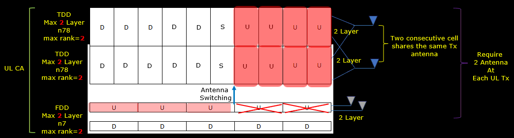
The purpose of this tutorial is to show you how to configure and test UL Tx Switching. The fundamental idea behind UL Tx Switching is can be illustrated below. The basic Idea can be summarized as below
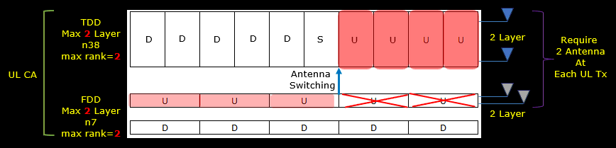
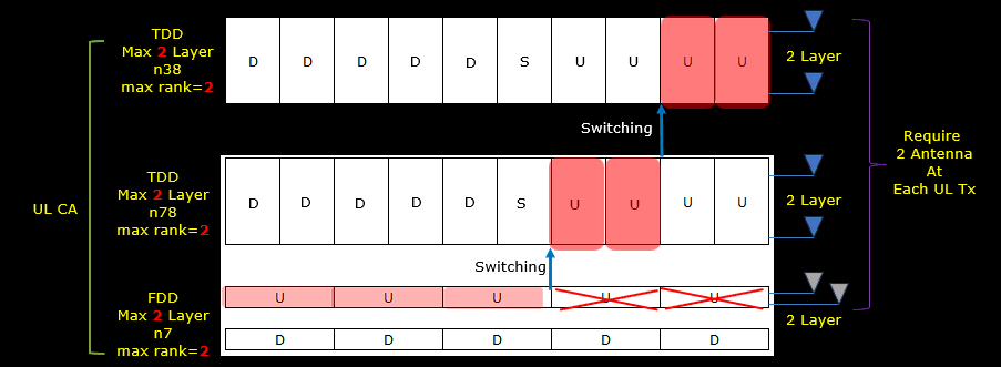
- Most of UE has limitation of Tx antenna (max two Tx antenna for most UE)
- So when they are configured for a communication setup that require more than two Tx antenna as shown in <Case A>. Two Tx antenna is not enough for fully utilizing the confituration.
- In practice with this limitation, UE can switch between mulciple carriers that best utilize the resource but still does not use more than two Tx antenna
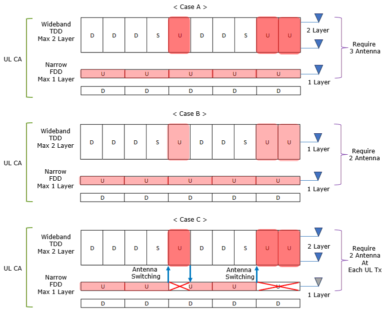
Image Source : Sharetechnote
Table of Contents
- NR SA UL TxSwitching
- Introduction
- Summary of the Tutorial
- Test Setup
- Key Configuration Parameters
- Test 1 : 1TX -> 2TX Switching, switchedUL (Rel 16)
- Test 2 : 2TX -> 2TX Switching, switchedUL (Rel 17)
- Test 3 : 2TX -> 2TX Switching(One Cell -> Two Contiguous Cell), switchedUL (Rel 17)
- Test 4 : 2TX -> 2TX Switching(One Cell -> Two Non Contiguous Cell), switchedUL (Rel 18)
- Test 5 : 2TX -> 2TX Switching(One Cell -> Two Non Contiguous Cell), switchedUL, User Defined Switching Point (Rel 18)
Introduction
Uplink (UL) Tx Switching is a critical feature in advanced wireless communication systems, particularly within the 5G New Radio (NR) framework, designed to optimize uplink transmission in scenarios where User Equipment (UE) is constrained by hardware limitations, notably the number of available transmit (Tx) antennas. In modern NR deployments, network configurations may require simultaneous transmissions across multiple uplink carriers to maximize throughput, enhance spectral efficiency, and support carrier aggregation. However, most commercial UEs are equipped with a maximum of two Tx antennas, which restricts their ability to fully exploit these multi-carrier configurations. UL Tx Switching addresses this limitation by enabling the UE to dynamically switch its transmit resources among different uplink carriers, ensuring compliance with hardware constraints while still achieving optimal utilization of available spectrum and network resources. This mechanism plays a significant role in scenarios such as dual connectivity, carrier aggregation, and uplink MIMO, where the efficient allocation and switching of transmission paths are essential for maintaining high data rates and robust connectivity. Understanding UL Tx Switching is pivotal for engineers and practitioners working with 5G NR, as it directly impacts system performance, device capability negotiation, and overall network planning in heterogeneous deployment environments.
-
Context of UL Tx Switching in 5G NR
- UL Tx Switching is an adaptation mechanism in 5G NR allowing UEs with limited Tx antennas to participate in multi-carrier uplink scenarios.
- It is part of strategies such as carrier aggregation and uplink MIMO, which are fundamental in meeting the throughput and reliability demands of modern wireless networks.
- The feature involves architectural coordination between the UE and the gNB (base station), considering both hardware capabilities and network configuration requirements.
-
Relevance and Importance of This Tutorial
- This tutorial provides a practical guide to configuring and testing UL Tx Switching, bridging theoretical understanding and real-world implementation in 5G NR systems.
- It is essential for professionals involved in network design, device testing, and optimization, as UL Tx Switching affects uplink scheduling, resource allocation, and overall service quality.
- Mastering UL Tx Switching configuration ensures that both network infrastructure and user devices can operate within their design limits while still achieving peak performance.
-
Learning Outcomes
- Gain an in-depth understanding of the technical principles and architectural components of UL Tx Switching in 5G NR.
- Develop hands-on skills for configuring UL Tx Switching in test and production environments.
- Be able to analyze and troubleshoot uplink performance issues related to Tx antenna limitations and multi-carrier operation.
- Interpret network signaling and UE capabilities related to UL Tx Switching for effective device-network integration.
-
Prerequisite Knowledge
- Familiarity with 5G NR architecture, including gNB and UE functional roles.
- Understanding of carrier aggregation, uplink scheduling, and basic MIMO concepts.
- Experience with network configuration, wireless protocol analysis, and device capability negotiation is beneficial.
- Basic knowledge of radio resource management and wireless communication principles will help maximize the value of this tutorial.
Summary of the Tutorial
This tutorial covers a series of test cases for NR UL Tx Switching (switchedUL mode) across multiple 3GPP releases (Rel-16, Rel-17, Rel-18), focusing on the configuration, execution, and log validation steps for each scenario. The main objective is to validate and demonstrate UL Tx switching behavior between different carrier combinations, antenna configurations, and user-specified switching controls.
-
Test 1: 1TX → 2TX Switching, switchedUL (Rel 16)
- Configure gNB and UE/UEsim for dual-carrier (CA) operation, with two antennas each for DL and UL (N_NR_ANTENNA_DL = 2, N_ANTENNA_UL = 2), but restrict UL max rank per carrier (e.g., carrier 1: rank 1, carrier 2: rank 1).
- Set up one FDD (carrier1) and one TDD (carrier2) cell, assign UL TX switching priorities, and enable UL CA on SCells.
- Activate UL TX switching mode via flags such as UL_TX_SWITCH_OPT and UL_TX_SWITCH_ACT, with the switching trigger based on UL channel quality (“ulquality”), using SRS reports to determine when to switch.
- Validate cell configuration with 'cell phy' and 'cell' commands.
- Power on the UE, establish 2CC CA, and monitor gNB log for proper capability negotiation and configuration:
- gNB requests UL Tx switching capability in UECapabilityEnquiry.
- UE reports supported band combinations for UL Tx switching and switching timing requirements.
- Review RRC reconfiguration to ensure correct maxRank and UL Tx switching carrier roles are applied per carrier.
- Observe Resource Block allocation to confirm switchedUL operation: UL is scheduled on one carrier at a time, with correct layer usage per carrier.
-
Test 2: 2TX → 2TX Switching, switchedUL (Rel 17)
- Apply nearly identical configuration as Test 1, but ensure the UE supports and advertises Release 17 UL Tx switching features in its capability information.
- Configure the test for both gNB and UE/UEsim, using dual-antenna settings for both carriers.
- Validate capability negotiation: gNB requests R17 features, and UE reports uplinkTxSwitchingPeriod2T2T if supported.
- Perform the test by establishing 2CC CA and confirming correct maxRank and UL Tx switching roles for each carrier via RRC reconfiguration.
- Confirm switchedUL operation and verify that the scheduler alternates UL transmission between carriers, utilizing the appropriate number of spatial layers as per configuration and UE capability.
-
Test 3: 2TX → 2TX Switching (One Cell → Two Contiguous Cells), switchedUL (Rel 17)
- Configure a three-cell system: one FDD cell (carrier1) and two contiguous TDD cells (carrier2).
- Assign dual antennas for DL and UL across all carriers, configure maxRank as needed (often max rank 2 for carrier 2).
- Set up UL Tx switching logic so that UL can be switched between the two contiguous TDD cells, controlled by uplink_tx_switch parameters and slot masks to specify eligible UL scheduling slots.
- Verify cell setup using 'cell phy' and related commands. Establish 3CC CA on the UE.
- During capability negotiation, ensure the UE advertises both inter-band and intra-band (contiguous) UL Tx switching support, including release-specific timing requirements (e.g., uplinkTxSwitchingPeriod2T2T for Rel-17).
- Check RRC reconfiguration steps to ensure each cell is properly assigned a UL Tx switching carrier role and maxRank.
- Confirm via logs and resource allocation maps that the scheduler switches UL between the two contiguous SCCs as expected under switchedUL operation, utilizing the maximum allowed spatial layers per carrier.
-
Test 4: 2TX → 2TX Switching (One Cell → Two Non-Contiguous Cells), switchedUL (Rel 18)
- Set up a three-cell scenario: one FDD cell (carrier1) and two non-contiguous TDD cells (e.g., n38 and n78 as carrier2).
- Assign dual-antenna configurations for all cells, with maxRank settings as appropriate for each carrier.
- Configure UL Tx switching via uplink_tx_switch parameters, ensuring slot masks and activation criteria align with test objectives.
- During capability exchange, verify the UE advertises Rel-18 features: support for multiple band-pair switching, twoTx mode, and specific switching period values per band pair.
- Validate RRC reconfiguration for correct maxRank and switching role assignments for each involved cell.
- Check that the scheduler switches UL between any two of the three (non-contiguous) cells according to user-defined criteria and that only one carrier is scheduled for UL at a time, with correct spatial layer usage.
-
Test 5: 2TX → 2TX Switching (One Cell → Two Non-Contiguous Cells), switchedUL, User Defined Switching Point (Rel 18)
- Setup is similar to Test 4, but the UL Tx switching point is explicitly defined by the user in the configuration (using UL_TX_SWITCH_SLOTS flag), rather than being determined dynamically by the gNB scheduler.
- Configure the testbed for three non-contiguous cells, assign appropriate antenna and maxRank values, and enable user-specified switching slots.
- Ensure the UE capability signaling covers all relevant band pairs and modes (twoTx true, switchedUL mode, per-pair switching periods) for Rel-18.
- Validate the test by confirming that the scheduler switches UL between carriers at user-defined points and that the UE transmits at the configured rank when active on each carrier.
- Review logs and resource allocation plots to confirm proper switchedUL operation and correct adherence to user-defined switching scheduling.
Across all tests, the methodology involves:
- Configuring the gNB and UE/UEsim with appropriate carrier, antenna, and switching parameters.
- Powering up and attaching the UE, ensuring capability negotiation and CA setup is successful.
- Validating the correct application of UL Tx switching parameters via RRC reconfiguration and log analysis.
- Observing system behavior (resource allocation, UL scheduling) to confirm the correct mode of switchedUL operation as per the test scenario (including spatial layer use and switching timing).
Key configuration parameters critical to these procedures include:
- uplink_tx_switch (enables and controls UL Tx switching features)
- role, period_location, carrier2_slots, activation (determine which carrier acts as carrier1/carrier2, the switching trigger, and eligible slots for switching)
- ul_quality_ri2_cqi_threshold, max_allowed_period (define thresholds and timing for switching activation)
The step-by-step approach ensures comprehensive validation of different UL Tx switching scenarios, covering both scheduler-driven and user-defined switching triggers, contiguous and non-contiguous carrier arrangements, and progressive feature sets across 3GPP releases.
Test Setup
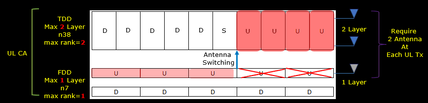
Test setup for this tutorial is as shown below.

Key Configuration Parameters
Followings are important configuration parameters for this tutorial. You may click on the items for the descriptions from Amarisoft documents.
Test 1 : 1TX -> 2TX Switching, switchedUL (Rel 16)
This test is to test and show the concept of a simplest cases of UL Tx Switching. It is the case where (according to the scheduling by gNB) UE switches from 1Tx carrier to 2Tx carrier with switchedUL mode.
The specific scenation implemented in this test is illustrated as below
Configuration
I used the enb-ul-tx-switching-CA-rel16.cfg on gNB (
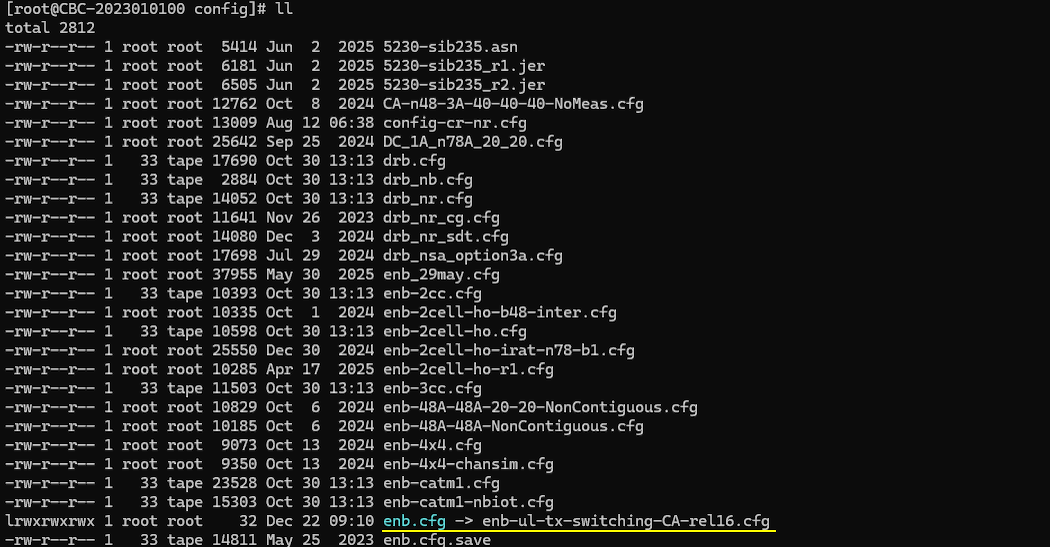
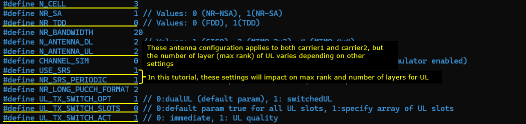
In enb-ul-tx-switching-CA-rel16.cfg, followings are configured.
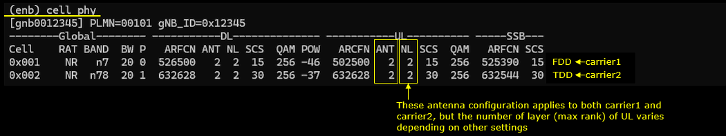
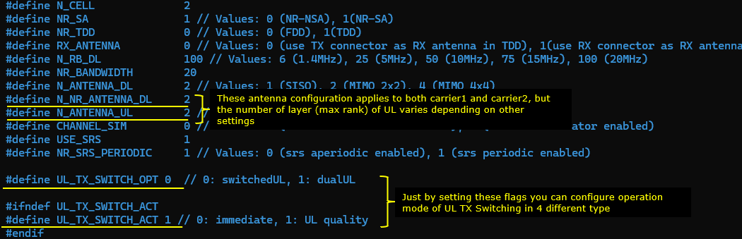
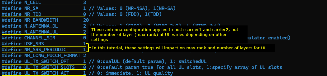
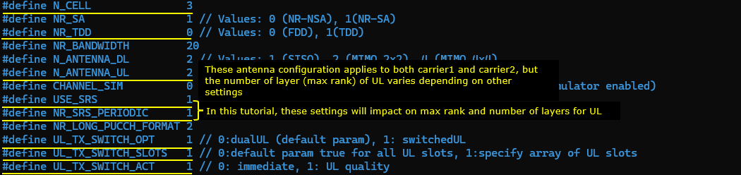
First note that two antenna is configured for DL for both carriers (N_NR_ANTENNA_DL = 2) and for UL for both carriers (N_ANTENNA_UL = 2). In this test, N_ANTENNA_UL = 2 does not necessarily mean 2 layer(rank 2). The number of layer(max rank) will be specified to 1 or 2 depending on the situation. (
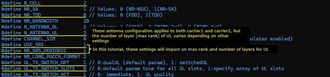
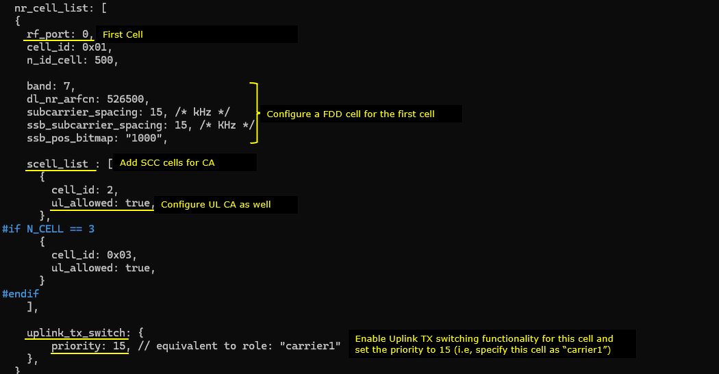
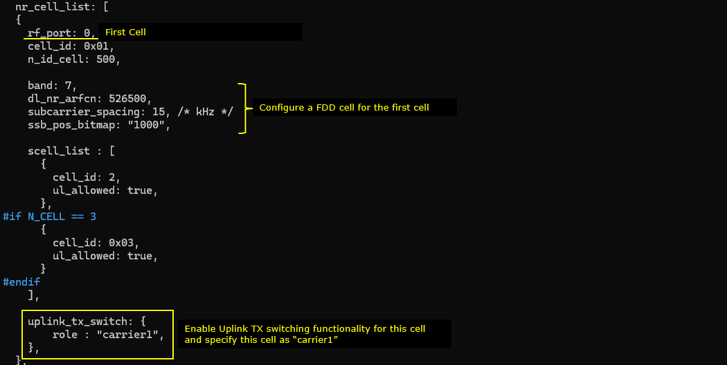
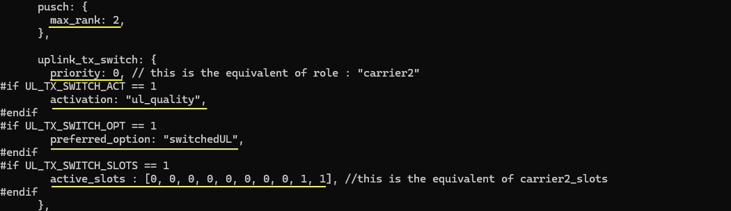
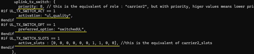
This configuration defines the first NR cell on rf_port: 0 and sets it up as an FDD cell (with subcarrier_spacing: 15 and ssb_subcarrier_spacing: 15). It then adds secondary cells for carrier aggregation using scell_list, and enables UL carrier aggregation on those SCells by setting ul_allowed: true. Finally, it enables NR UL TX switching for this cell with priority: 15, which assigns the UL Tx switching priority for the band (lower value means higher priority); in a 2-cell setup, priority: 15 corresponds to the carrier1 role, while priority: 0 corresponds to carrier2.
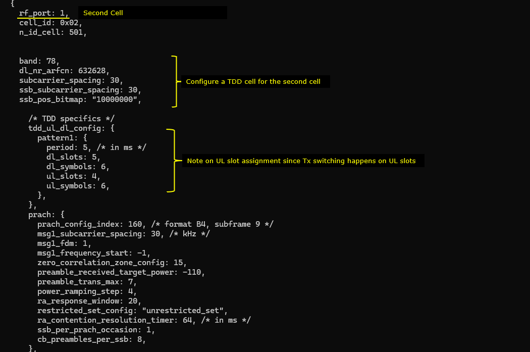
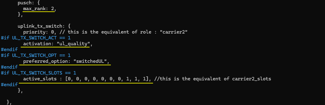
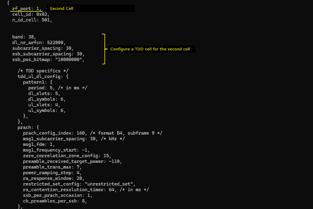
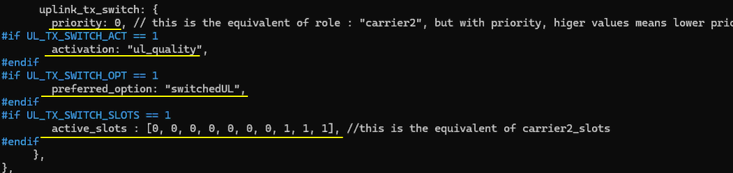
This second nr_cell_list entry configures a TDD NR cell on rf_port: 1 (with subcarrier_spacing: 30 and ssb_subcarrier_spacing: 30) and defines its TDD timing using tdd_ul_dl_config.pattern1 (e.g., dl_slots, dl_symbols, ul_slots, ul_symbols), because UL TX switching decisions matter on UL-capable slots/symbols. UL TX Switching is enabled with uplink_tx_switch.priority: 0, which gives this band the highest UL TX switching priority (and in a 2-cell setup corresponds to the “carrier2” role). The switching behavior is further controlled by uplink_tx_switch.activation (e.g., "ul_quality"), optionally constrained by uplink_tx_switch.preferred_option (e.g., "switchedUL"), and time-gated by uplink_tx_switch.active_slots, which acts like the carrier-specific slot mask (the equivalent of carrier2_slots) telling the scheduler which slots are eligible for UL scheduling on this carrier when switching is triggered.
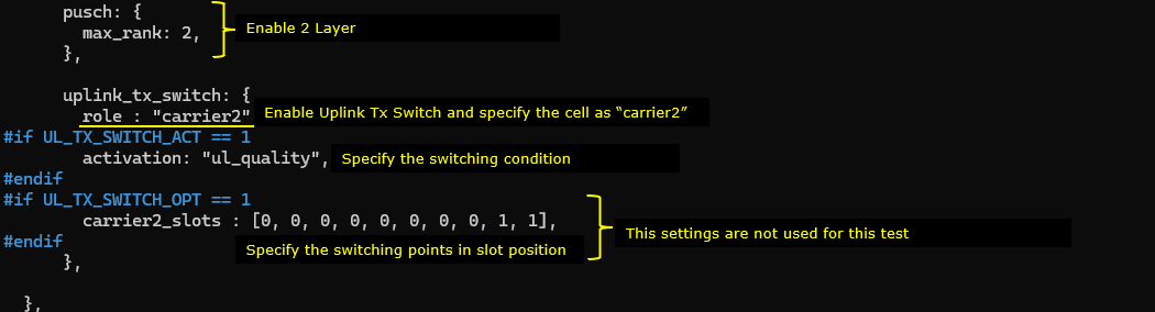
In most of the use case, the max rank of carrier 2 is set to 2. The mode of UL Tx Activation is set to 'ulquality'. In this mode, UL Tx Switching happens based on the quality of UL channel. UL Tx Switching will be activated when the signal on carrier 2 (as measured by SRS) has an UL rank greater than 1 and an UL CQI above ul_quality_ri2_cqi_threshold
Perform the Test
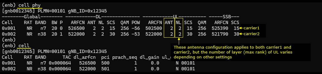
Check if the cell is configured as intended. Check out the output of 'cell phy' and cell command.
Now power on UE and wait until it completes attach and establishment of 2CC CA for both uplink and downlink.
Log Analysis
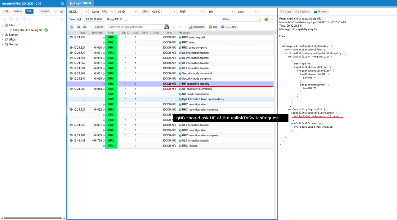
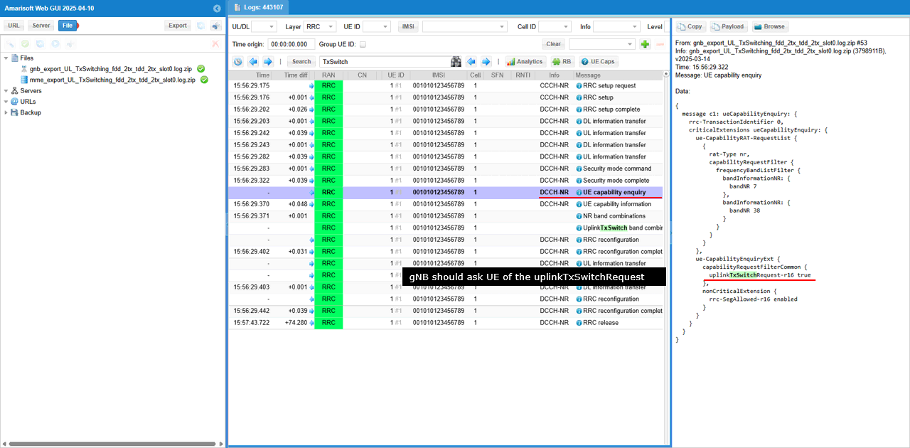
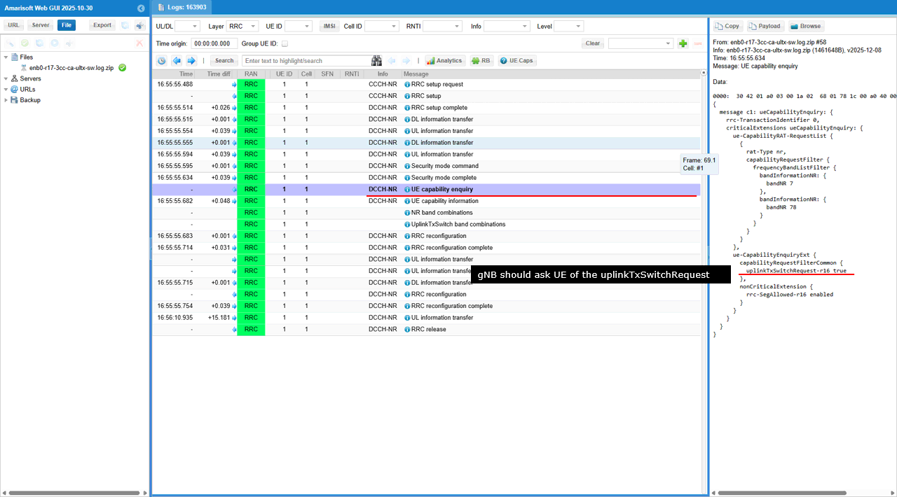
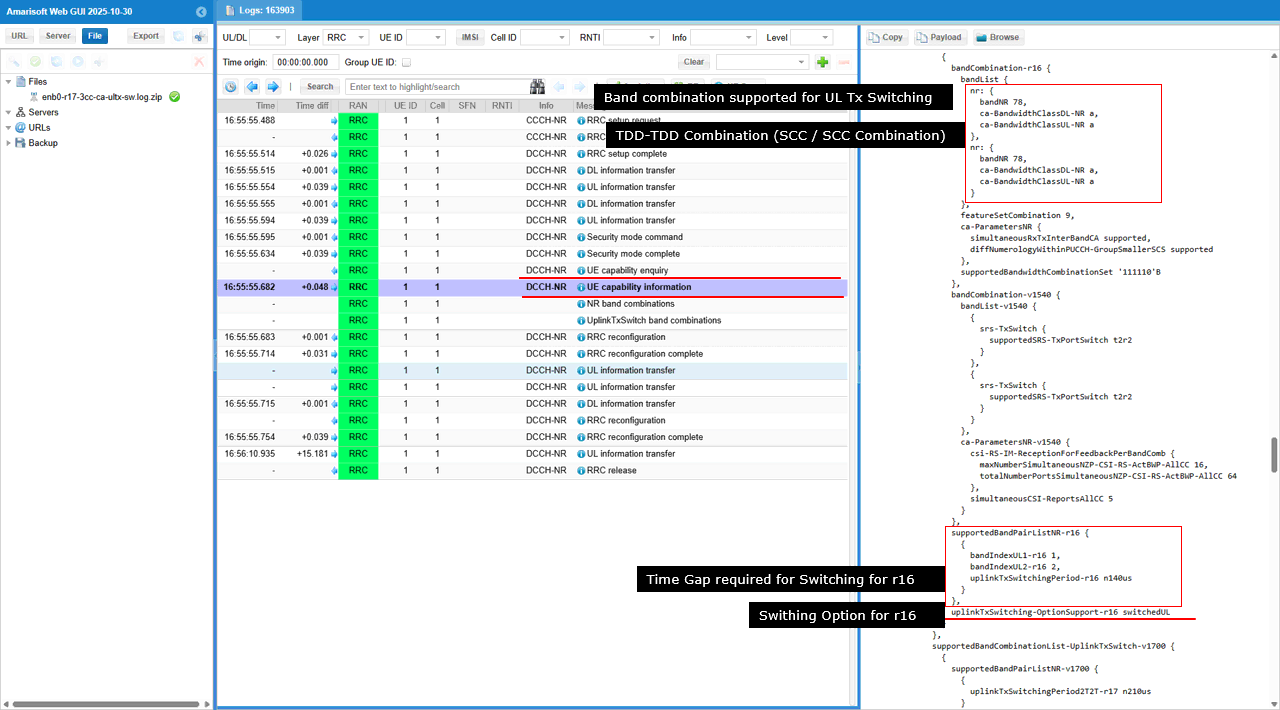
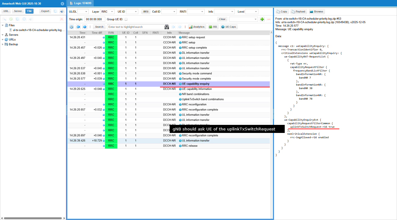
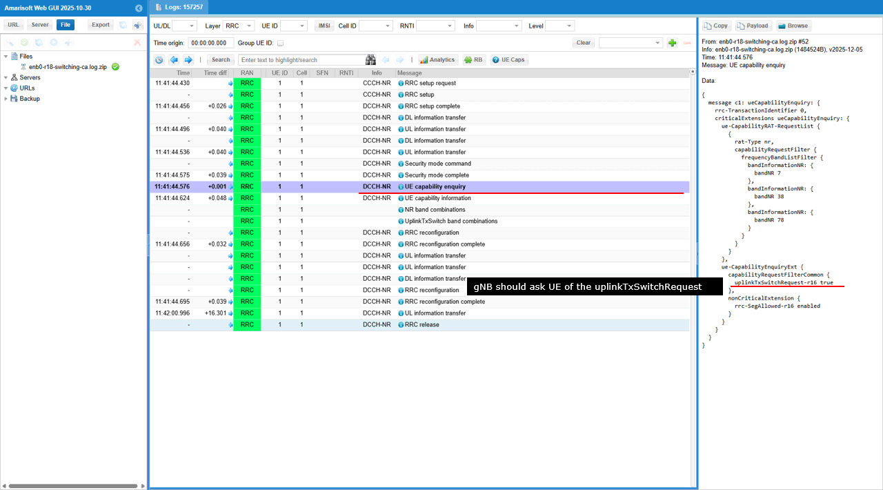
The gNB sends UECapabilityEnquiry and sets ue-CapabilityEnquiryExt -> ue-CapabilityRequestFilterCommon -> uplinkTxSwitchRequest-r16: true. This explicitly requests the UE to include its NR UL TX Switching (Rel-16) capability information in the subsequent UECapabilityInformation, so the gNB can decide whether UL TX switching can be enabled and how it should be configured for the UE.
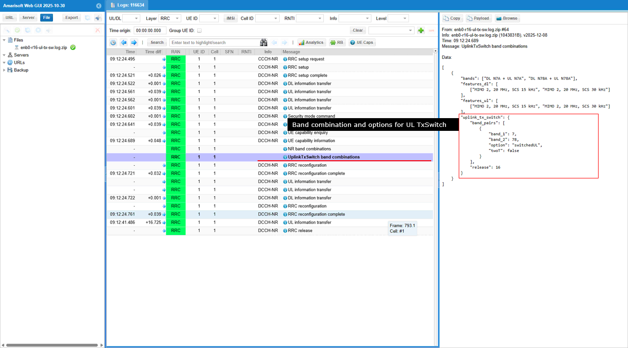
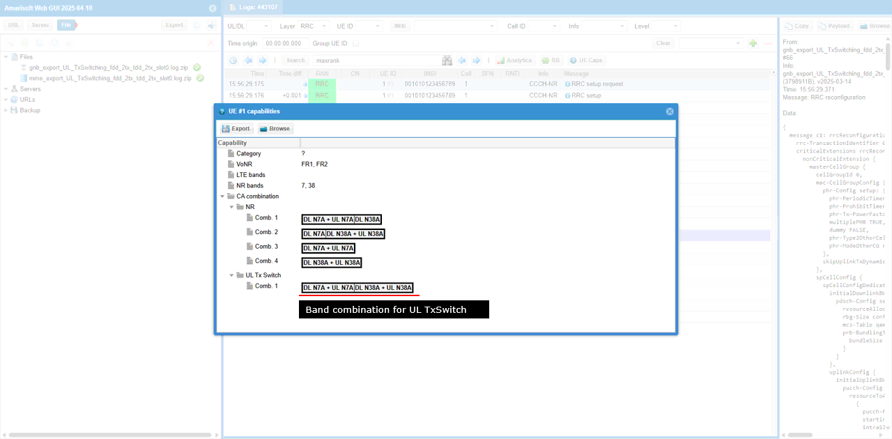
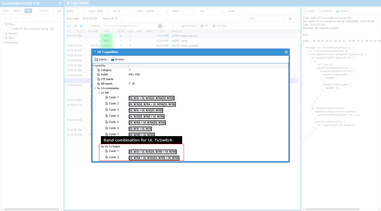
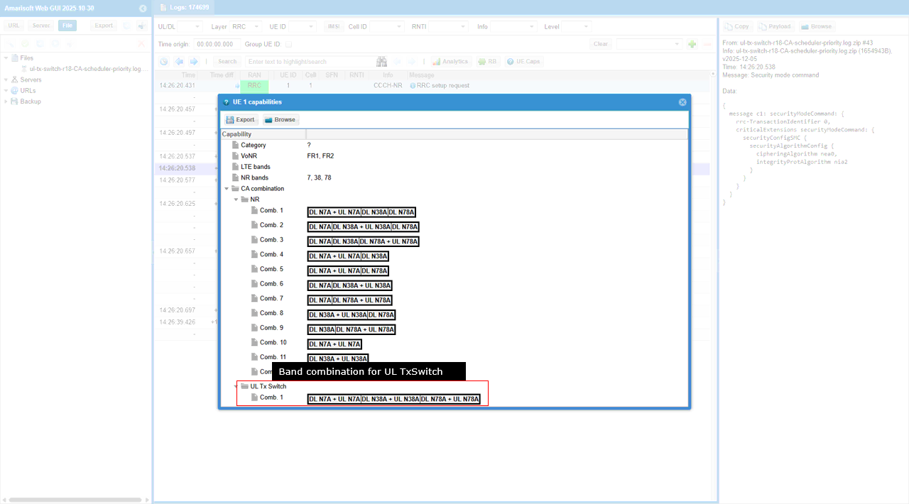
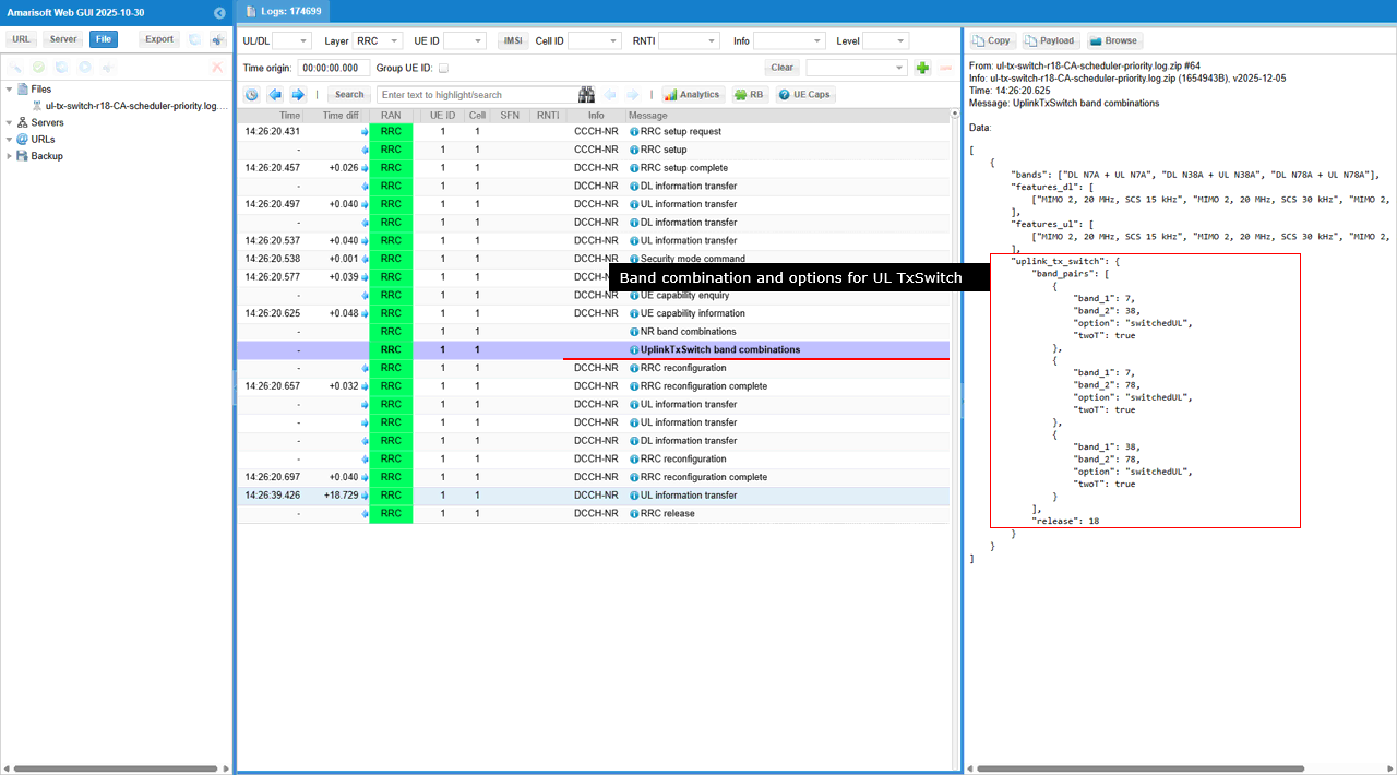
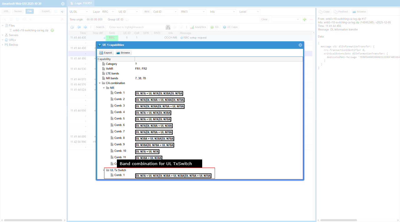
This UE capability view shows that the UE reports a dedicated “UL Tx Switch” band combination, meaning it supports UL Tx switching between two UL-capable NR carriers under a specific CA setup. In the example, UL Tx Switch → Comb. 1 indicates a configuration like DL n7A + UL n7A together with DL n78A + UL n78A, where the UE can keep the overall CA band combination active but select which UL carrier actually gets the UE transmitter (switching UL between n7 and n78 according to the gNB’s UL Tx switching control).
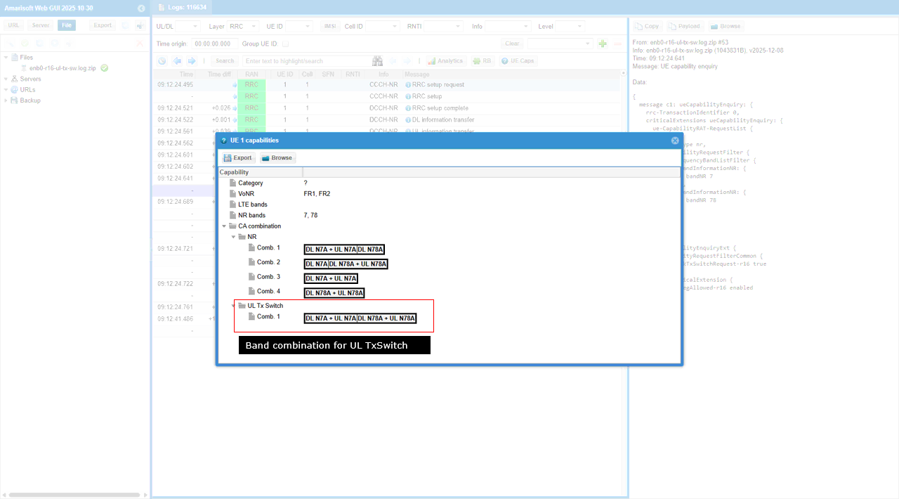
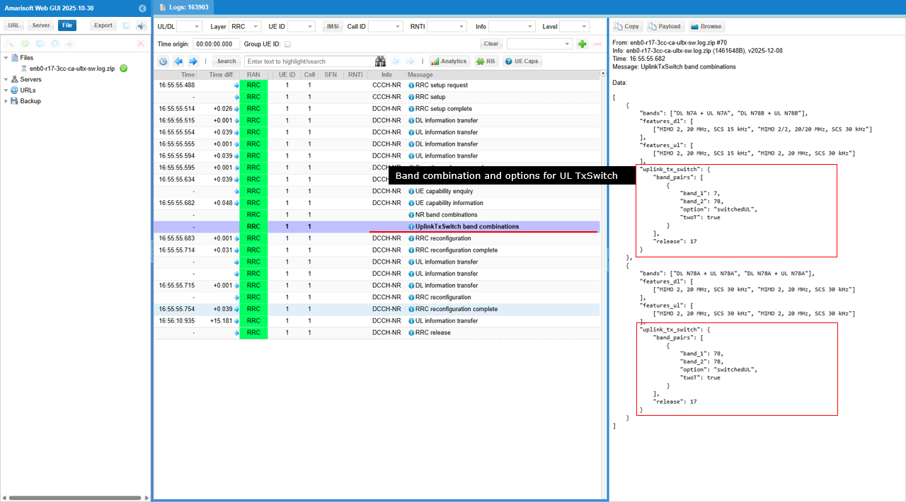
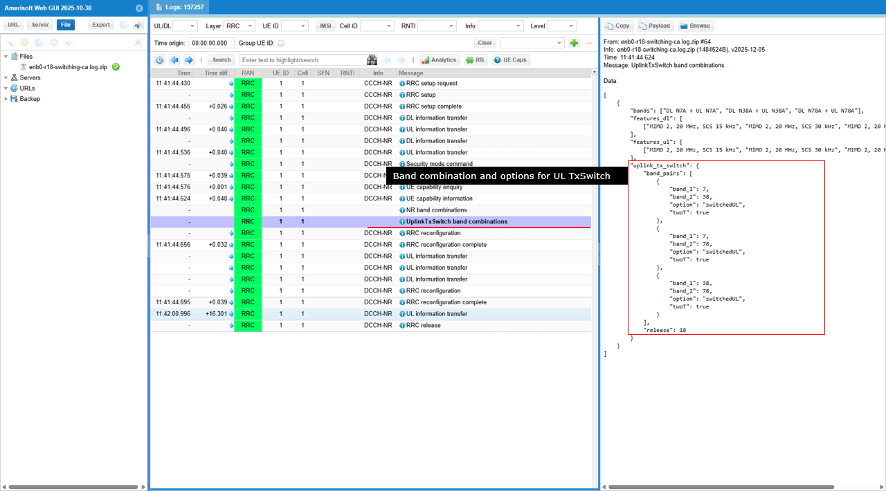
This is more detailed information about UL Tx Switching. This UplinkTxSwitch band combinations capability report tells the gNB that the UE supports an UL Tx switching CA combination with bands: ["DL N7A + UL N7A", "DL N78A + UL N78A"], and it describes the UL Tx switching behavior via uplink_tx_switch.band_pairs where band_1: 7 and band_2: 78 are paired with option: "switchedUL" and twoT: false (i.e., UL is switched between the two carriers rather than transmitting UL on both at the same time). The presence of release: 16 indicates this is the UE’s Rel-16 UL Tx switching capability set that the gNB can use when deciding whether to activate UL Tx switching and how to schedule UL on n7 vs n78.
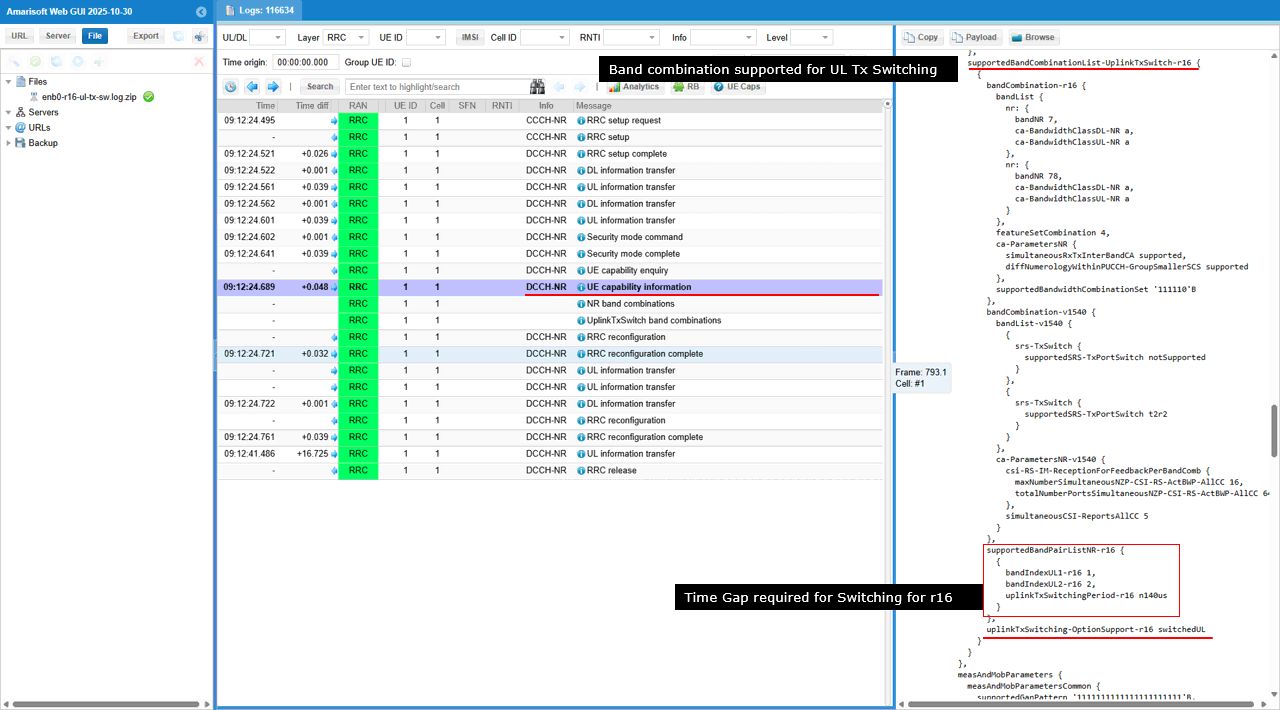
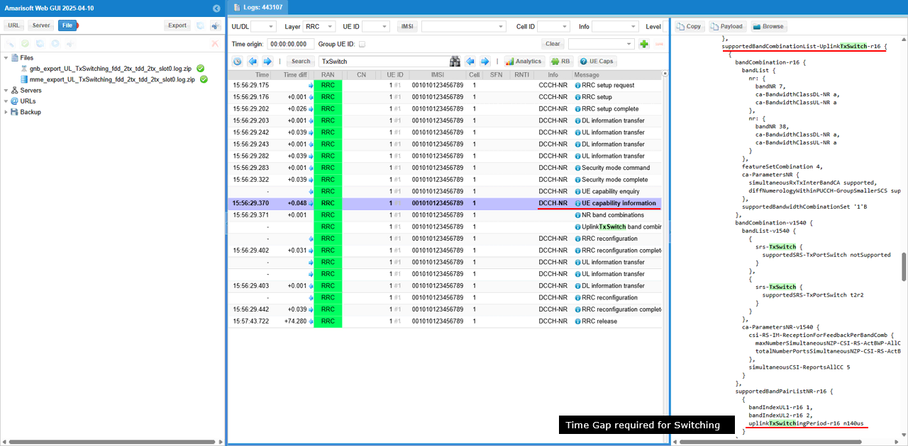
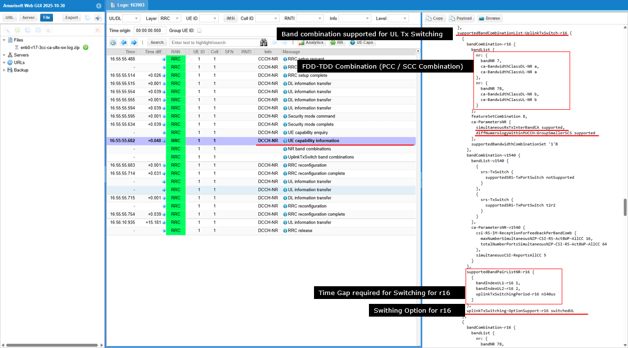
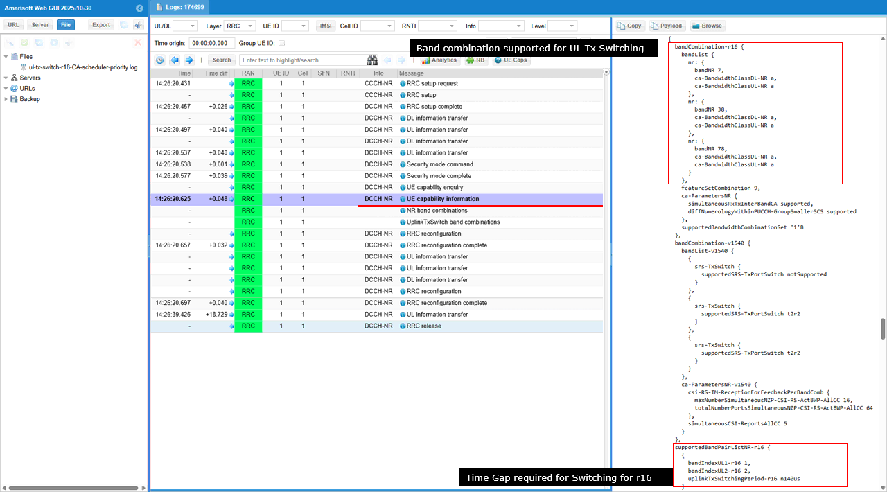
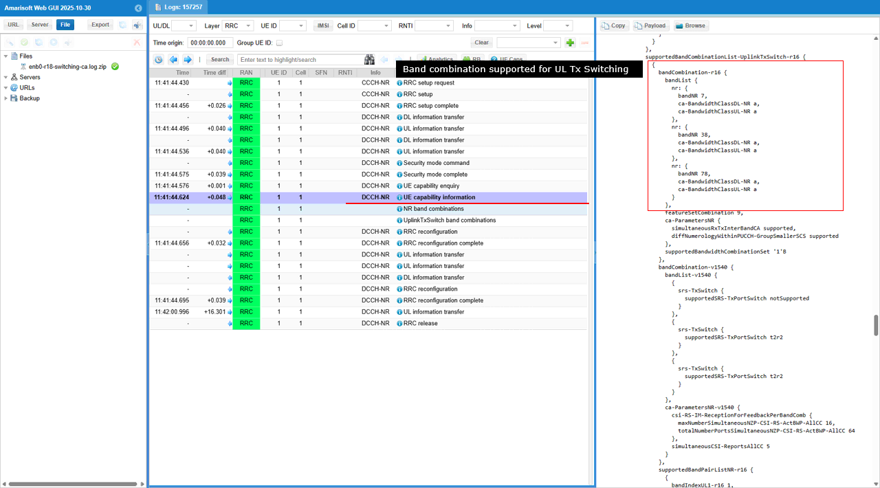
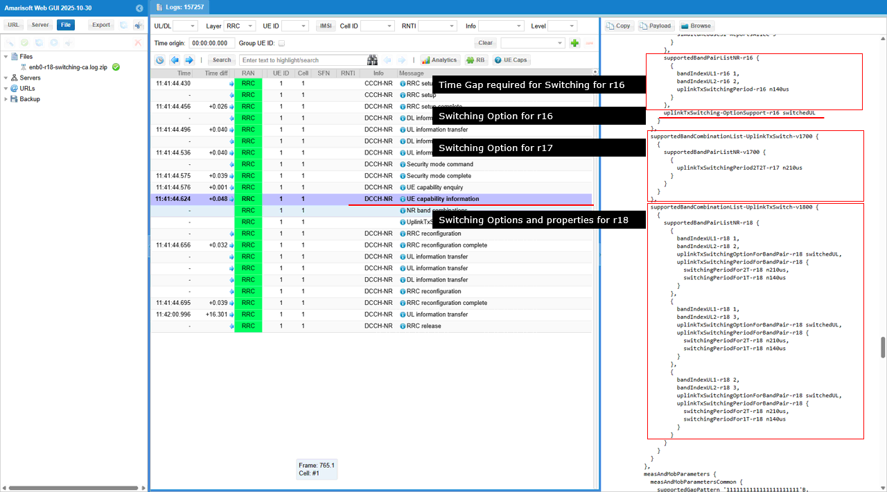
This UE capability information shows that the UE supports UL Tx switching for a specific NR CA pair under supportedBandCombinationList-uplinkTxSwitch-r16. In supportedBandPairListNR-r16, the UE reports bandIndexUL1-r16: 1 and bandIndexUL2-r16: 2, and it also provides uplinkTxSwitchingPeriod-r16: n140us, which is the minimum time gap the UE needs to switch its UL transmitter between the two UL bands. The UE further confirms the supported switching mode via uplinkTxSwitching-OptionSupport-r16: switchedUL, meaning UL is performed on one carrier at a time with switching, rather than simultaneous UL transmission on both carriers
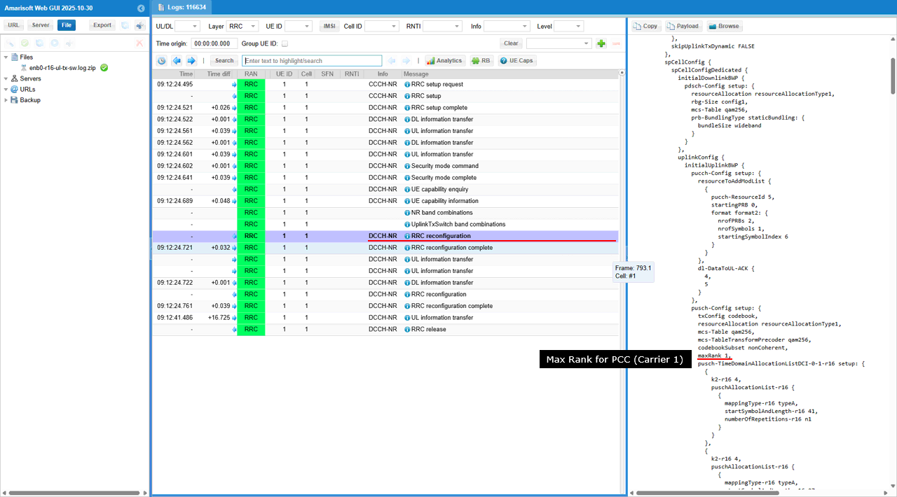
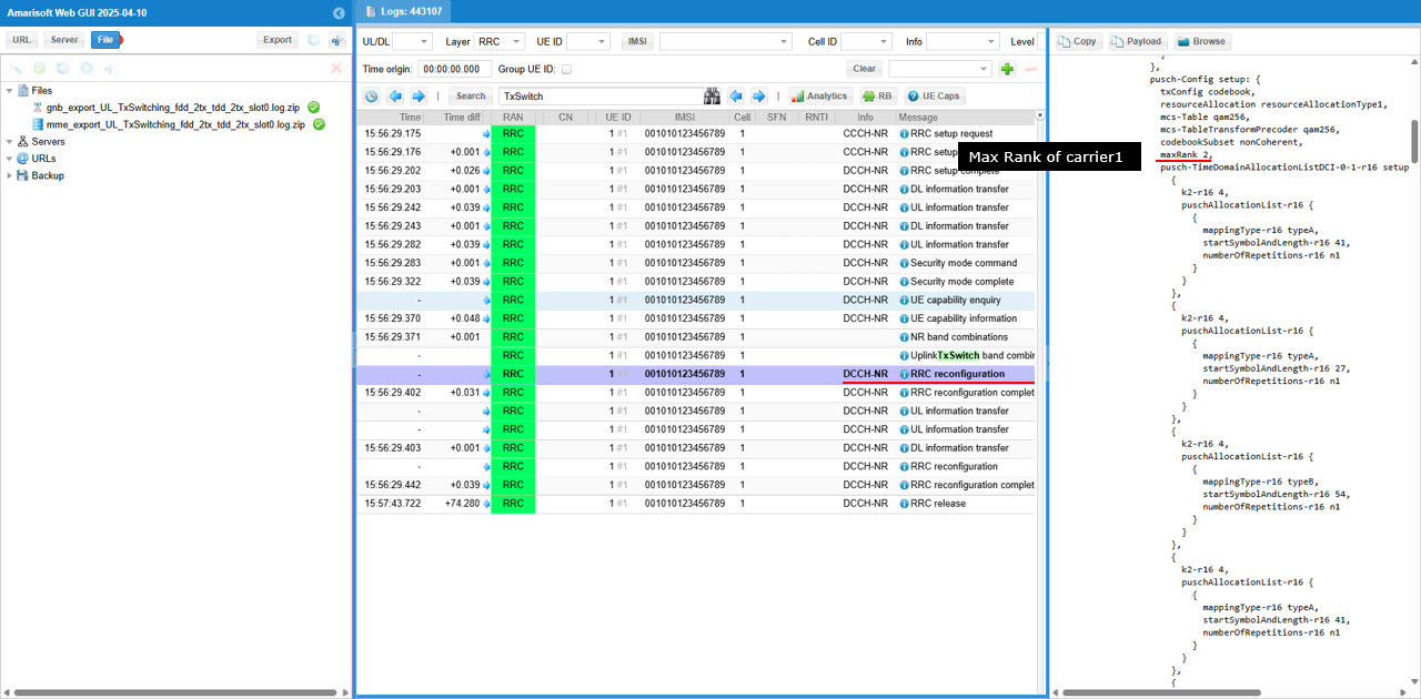
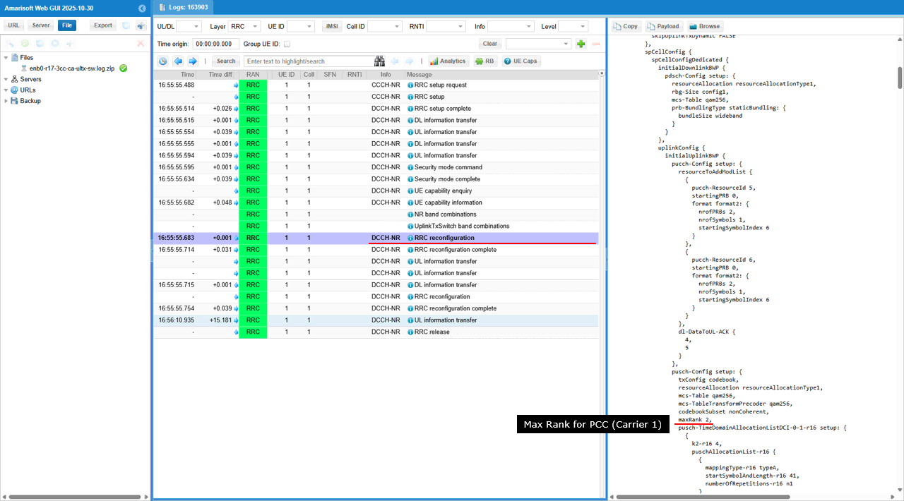
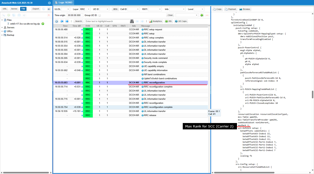
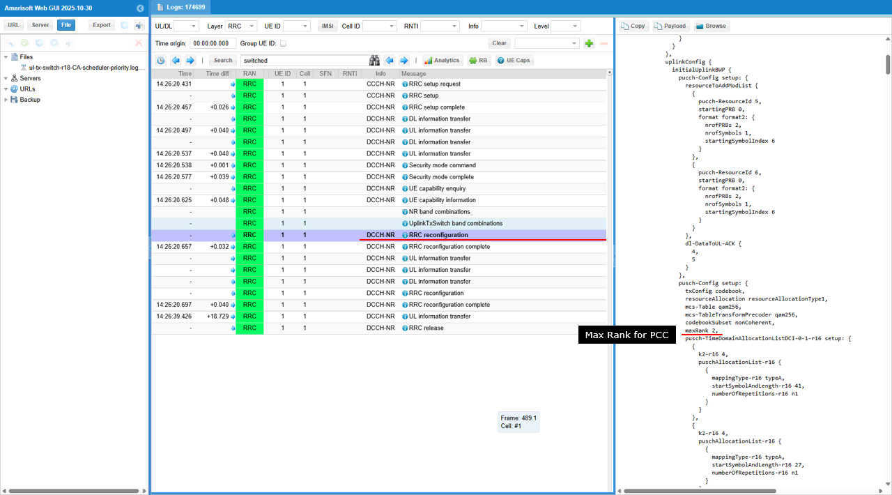
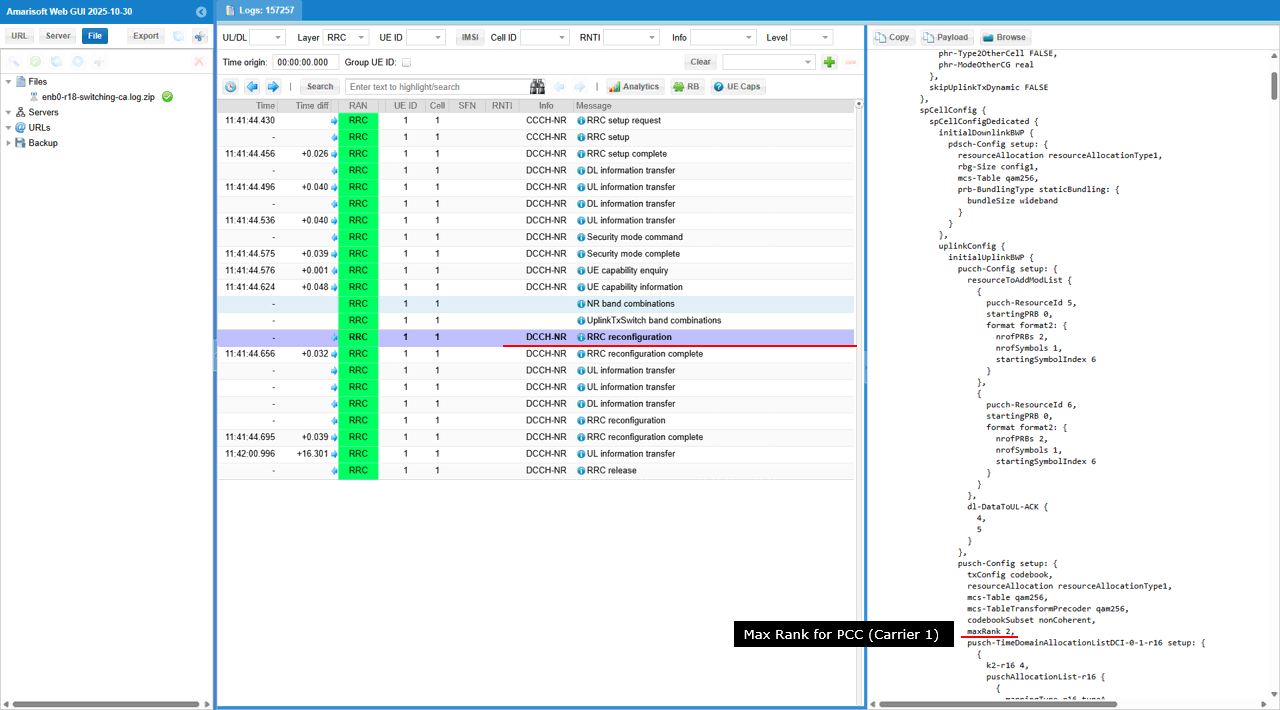
In this RRC reconfiguration, the gNB configures the PCC (carrier1) UL MIMO limit by setting pusch-Config.setup.maxRank: 1. This means the UE is only allowed to transmit rank-1 (single-layer) PUSCH on this carrier, so even when NR UL TX switching selects this carrier for UL in a given slot, the scheduler must keep UL transmission to one layer (no rank-2/4 UL) while this carrier is the active UL leg.
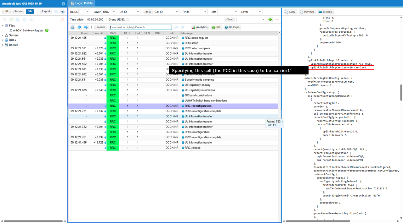
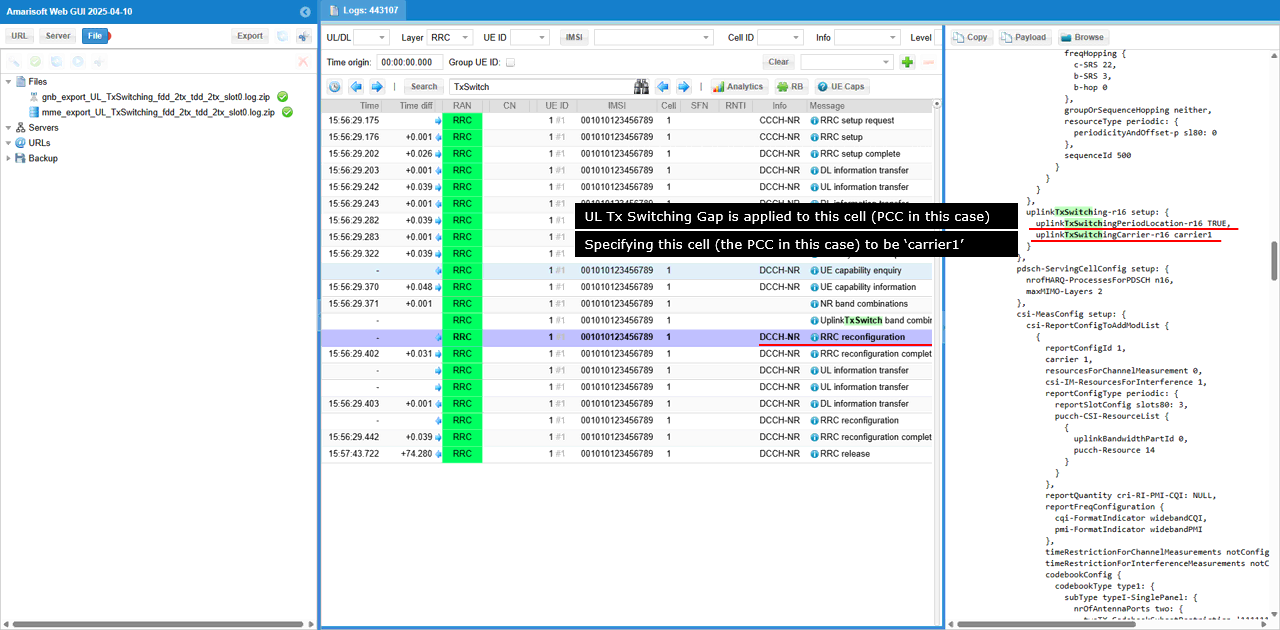
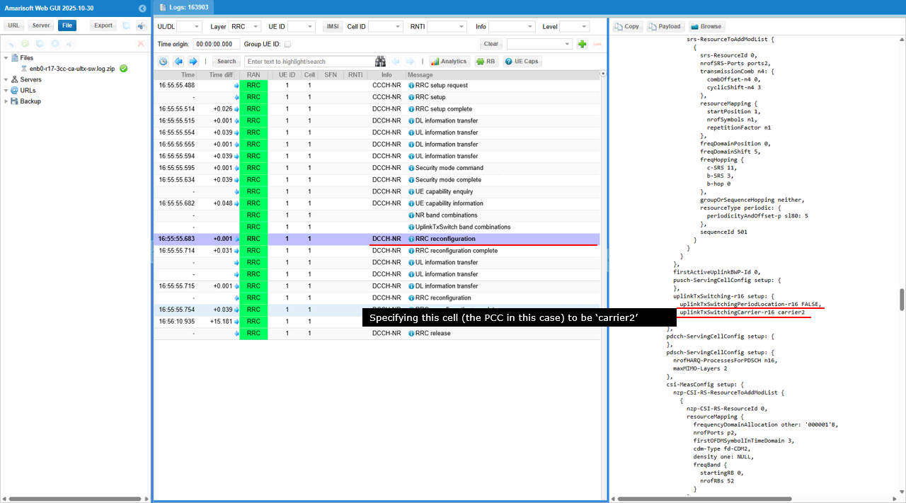
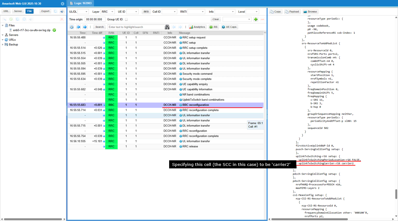
In this RRC reconfiguration, the gNB enables the UL Tx switching configuration by setting uplinkTxSwitching-r16.setup.uplinkTxSwitchingPeriodLocation-r16: TRUE, and it assigns the UL Tx switching “carrier1” role to this cell via uplinkTxSwitching-r16.setup.uplinkTxSwitchingCarrier-r16: carrier1. This means the PCC is explicitly labeled as the carrier1 side of the UL Tx switching pair, so when switching is triggered the scheduler treats this cell as the carrier1 leg and applies the UL Tx switching timing/slot rules accordingly.
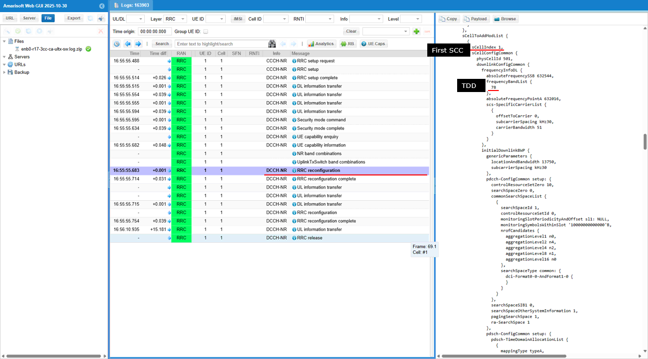
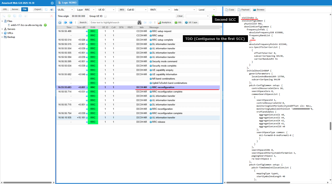
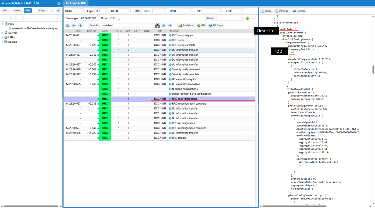
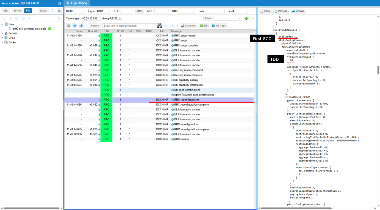
In this RRC reconfiguration, the gNB adds an SCC using sCellToAddModList with sCellIndex: 1, and it defines that SCC as a TDD carrier in band n78 via frequencyBandList: 78. The SCC’s carrier numerology is set through scs-SpecificCarrierList.subcarrierSpacing: kHz30 (with its own absoluteFrequencyPointA / SSB frequency parameters), so this SCC becomes the n78 TDD leg that can participate in NR UL TX switching together with the other UL-capable carrier.
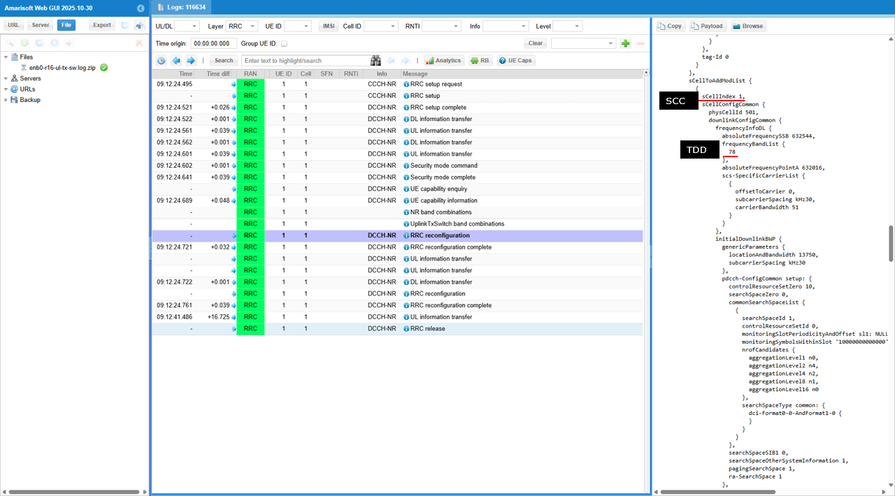
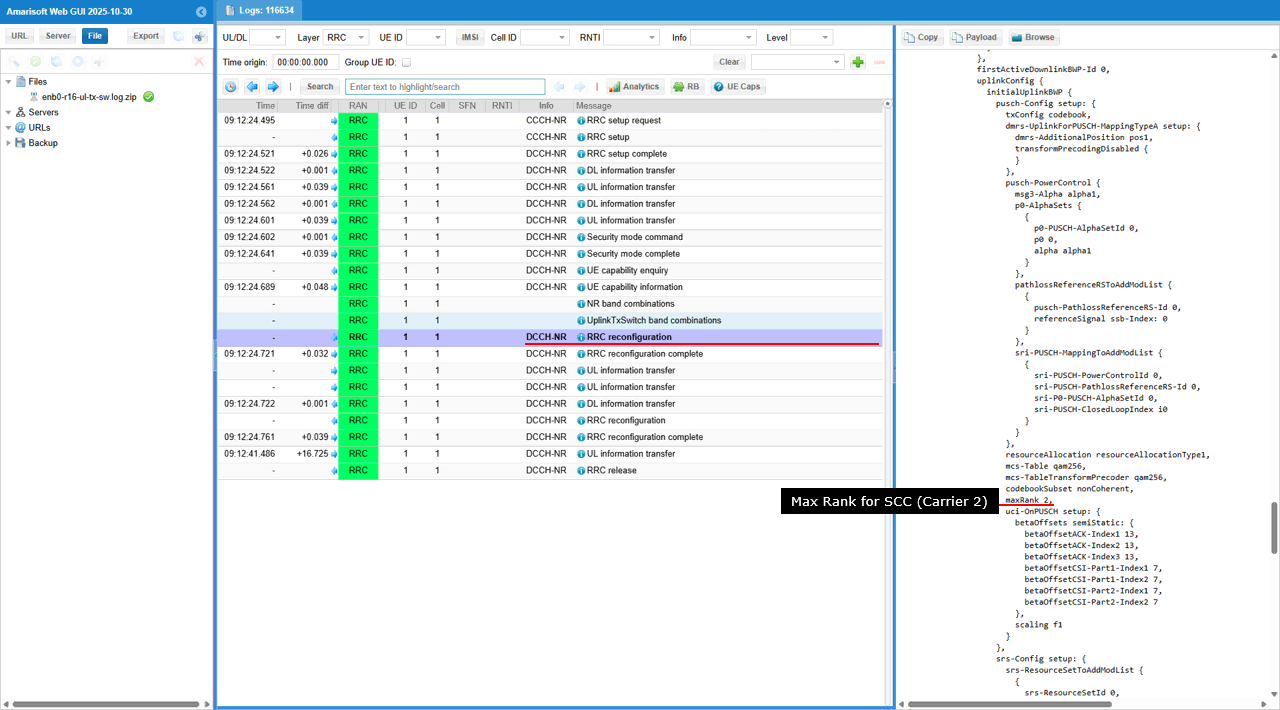
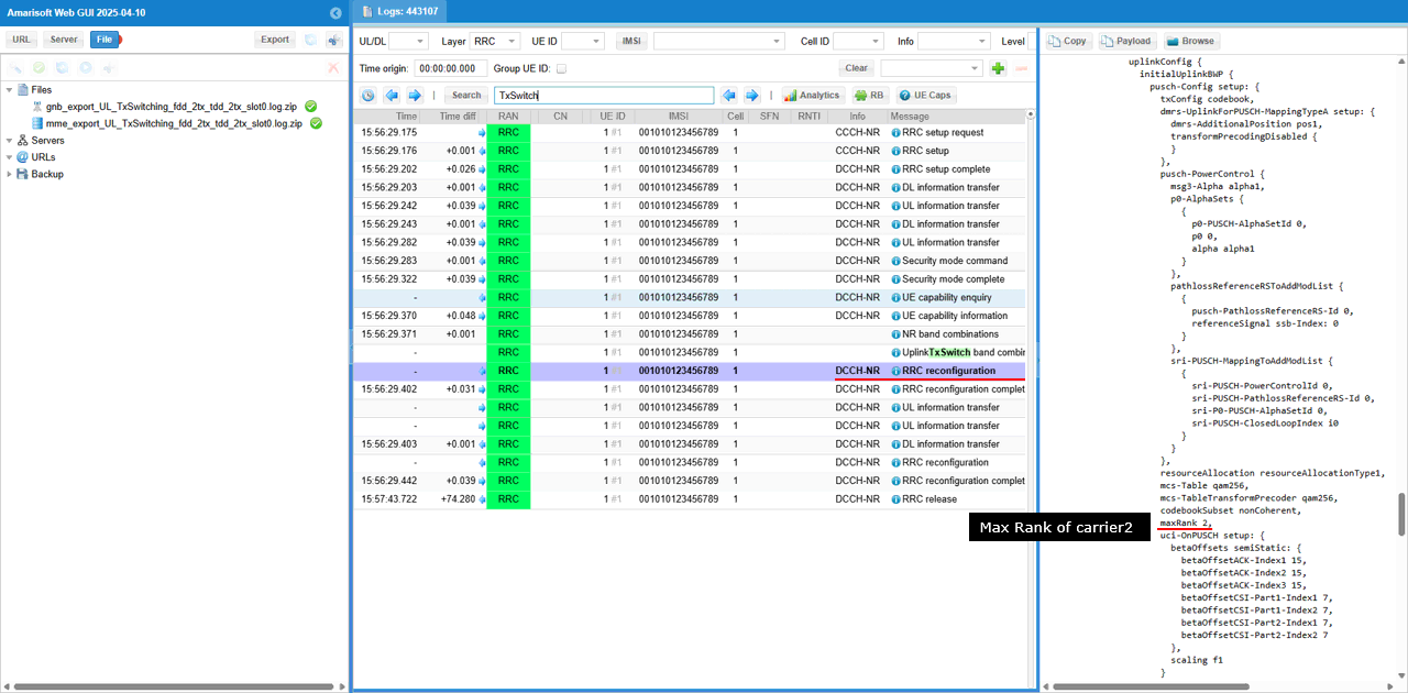
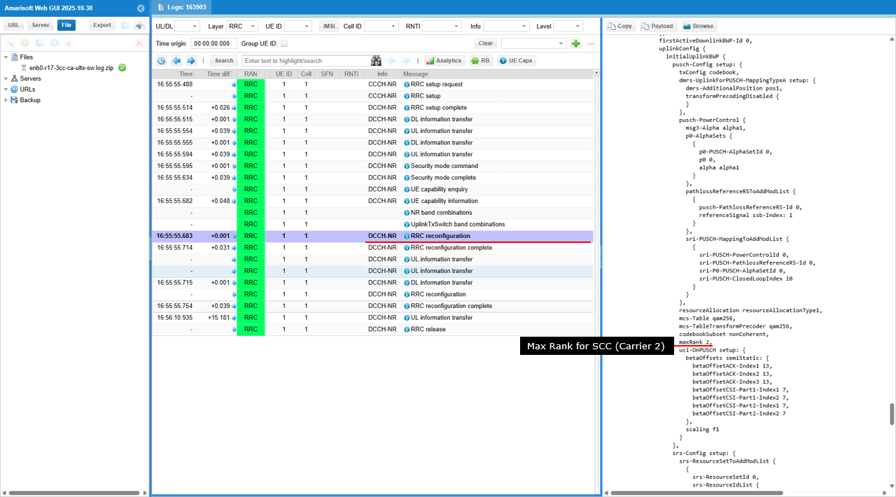
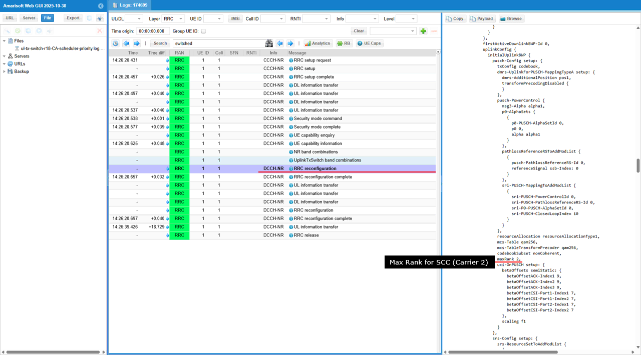
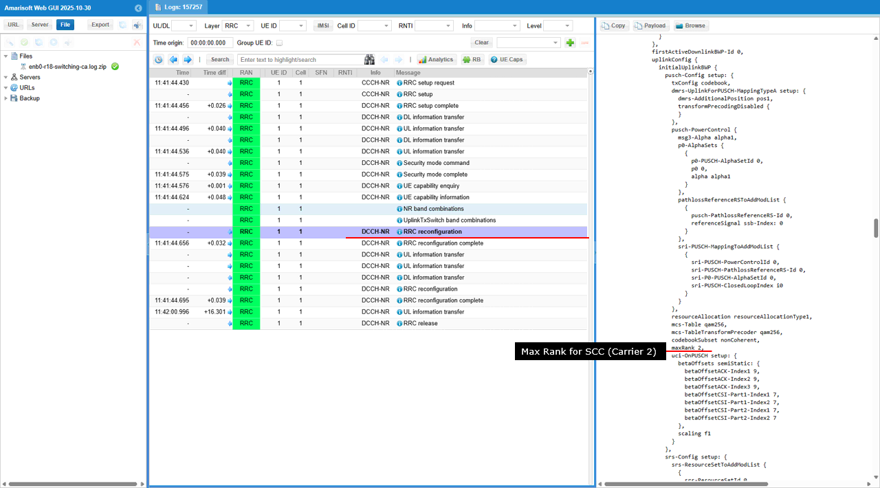
In this RRC reconfiguration, the gNB configures the SCC (the UL Tx switching “carrier2” side) to allow higher UL MIMO by setting pusch-Config.setup.maxRank: 2. This means that when UL Tx switching selects this SCC for UL transmission in a given slot, the UE may transmit up to rank-2 (two layers) on PUSCH on this carrier, unlike the PCC case where maxRank: 1 limited it to single-layer UL.
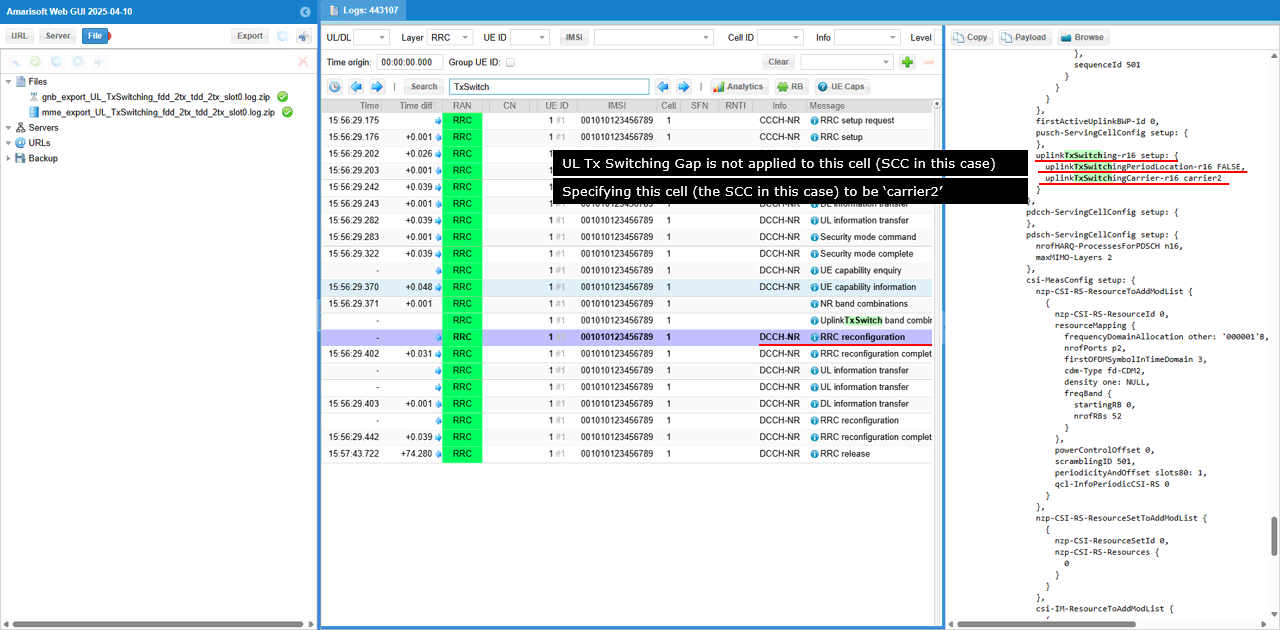
In this RRC reconfiguration, the gNB assigns this cell the UL Tx switching “carrier2” role by setting uplinkTxSwitching-r16.setup.uplinkTxSwitchingCarrier-r16: carrier2. It also sets uplinkTxSwitching-r16.setup.uplinkTxSwitchingPeriodLocation-r16: FALSE, meaning the configuration does not indicate that the UL Tx switching period information is provided via the “period location” signaling, so this cell is mainly being identified as the carrier2 leg of the UL Tx switching pair for subsequent UL scheduling and switching control.
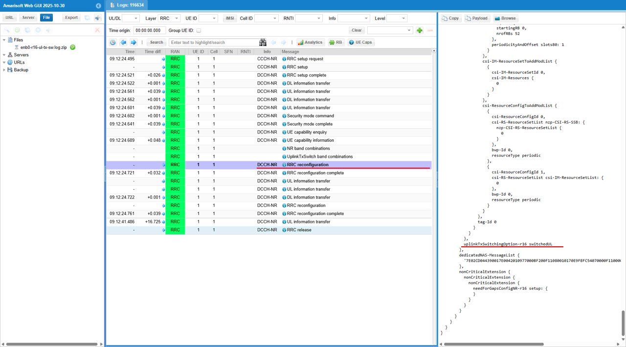
uplinkTxSwitchingOption-r16: switchedUL tells UE that UL Tx switching is done by switching the UE transmitter between the two UL carriers. UE transmits UL on only one carrier at a time, and it moves the UL transmission to the other carrier when switching is triggered. As a result, the scheduler should not expect simultaneous UL transmission on both carriers, and it must account for the switching gap when changing the active UL carrier.
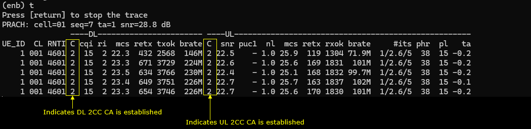
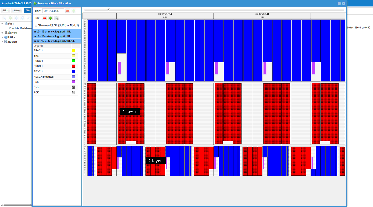
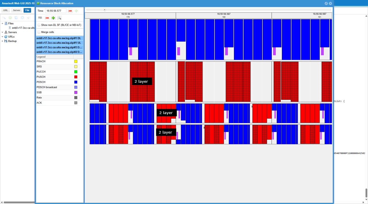
This Resource Block Allocation view shows how the gNB is using NR UL Tx Switching across two carriers. The PCC UL view is dominated by PUSCH (red) and it is scheduled as 1 layer, which matches the earlier pusch-Config.maxRank: 1 setting on the PCC. The SCC (TDD) DL/UL view shows alternating PDSCH (blue) and PUSCH (red), and the UL part is scheduled as 2 layer, which matches pusch-Config.maxRank: 2 on the SCC. With uplinkTxSwitchingOption-r16: switchedUL, the UL transmission is effectively placed on one carrier at a time, so you see UL activity concentrated on the PCC (rank1) in some intervals and on the SCC (rank2) in other intervals, aligned with the SCC’s UL-capable TDD slots.
Test 2 : 2TX -> 2TX Switching, switchedUL (Rel 17)
This test is to test and show the concept of a simplest cases of UL Tx Switching. It is the case where (according to the scheduling by gNB) UE switches from 1Tx carrier to 2Tx carrier with switchedUL mode.
The specific scenation implemented in this test is illustrated as below
Configuration
I used the gnb_tx_switch_fdd_2tx_tdd_2tx_slot0.cfg on gNB (
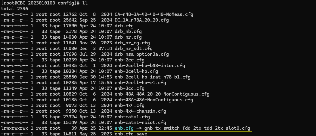
In gnb_tx_switch_fdd_2tx_tdd_2tx_slot0.cfg , followings are configured.
First note that two antenna is configured for DL for both carriers (N_NR_ANTENNA_DL = 2) and for UL for both carriers (N_ANTENNA_UL = 2). In this test, N_ANTENNA_UL = 2 does not necessarily mean 2 layer(rank 2). The number of layer(max rank) will be specified to 1 or 2 depending on the situation. (
This is the configuration for the first cell. The cell is configured to be FDD and assigned as "carrier1".
Following is the configuration of the second cell. In UL Tx Switching situation, the second cell is configured to TDD and assigned as 'carrier2. In most of the use case, the max rank of carrier 2 is set to 2. The mode of UL Tx Activation is set to 'ulquality'. In this mode, UL Tx Switching happens based on the quality of UL channel. UL Tx Switching will be activated when the signal on carrier 2 (as measured by SRS) has an UL rank greater than 1 and an UL CQI above ul_quality_ri2_cqi_threshold
Perform the Test
Check if the cell is configured as intended. Check out the output of 'cell phy' and cell command.
Now power on UE and wait until it completes attach and establishment of 2CC CA for both uplink and downlink.
Log Analysis
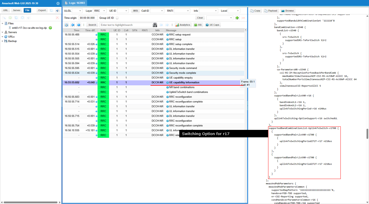
The first thing to be checked out in the log is about whether the uplinkTxSwitchRequest is configured in ueCapabilityEnquiry.
Then check out the band combination for UL Tx Switch in UE capability Information are properly set as you expected. Make it sure and check, check, check on this since there are many cases where a certain feature is not activated properly due to mismatch between what UE are really capable and what is configured in configuration file.
In case of UL Tx UL Switch Release 16, just a few notification would be enough (uplinkTxSwitchingPeriod, uplinkTxSwitching-OptionSupport for example as in this case).
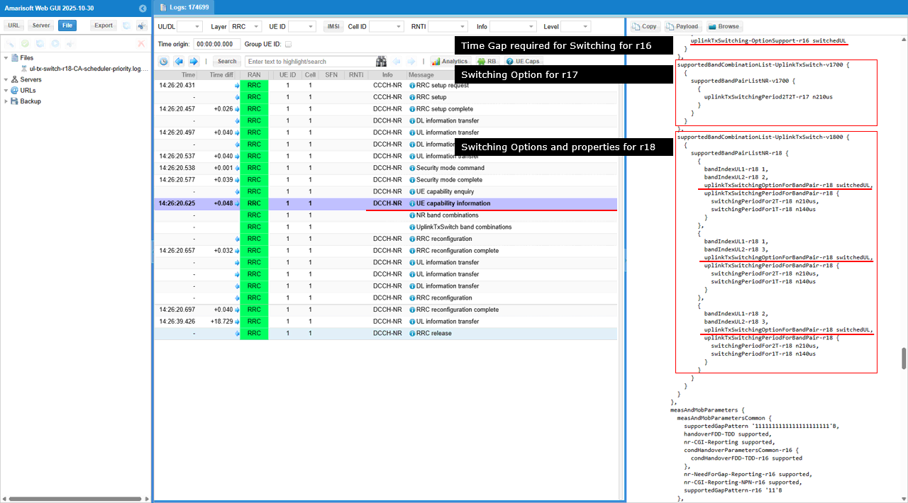
In case of UL Tx UL Switch Release 17, you would see the Rel 17 feature notification like uplinkTxSwitchingPeriod2T2T.
Once gNB think it got everything to make any decision to enable UL Tx Switching, it configures the switching in RRC Reconfiguration.
First gNB configures maxRank for the carrier2 (If the carrier1 is PCC cell as in this case, you need to check this under spCellConfig IE) in RRC Reconfiguration.
Then it configures uplinkTxSwitchingPeriodLocation and uplinkTxSwitchingCarrier in uplinkTxSwitching IE. If the switching happens between PCC and SCC in UL CA, usually PCC is designated to be carrier1 and uplinkTxSwitchingPeriodLocation is set to TRUE.
Then gNB configures UL maxRank of carrier2 to 2. You can confirm on this with maxRank IE of SCC UL in this test.
Then it configures uplinkTxSwitchingPeriodLocation and uplinkTxSwitchingCarrier in uplinkTxSwitching IE. If the switching happens between PCC and SCC in UL CA, usually SCC is designated to be carrier2 and uplinkTxSwitchingPeriodLocation is set to FALSE.
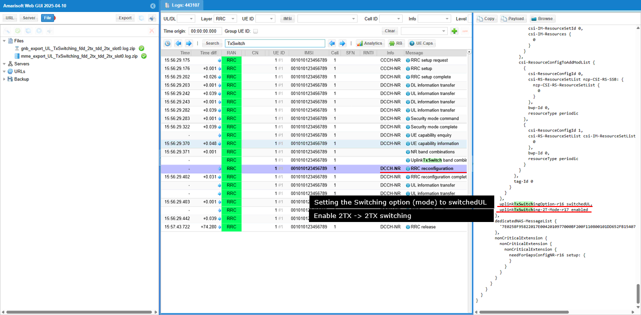
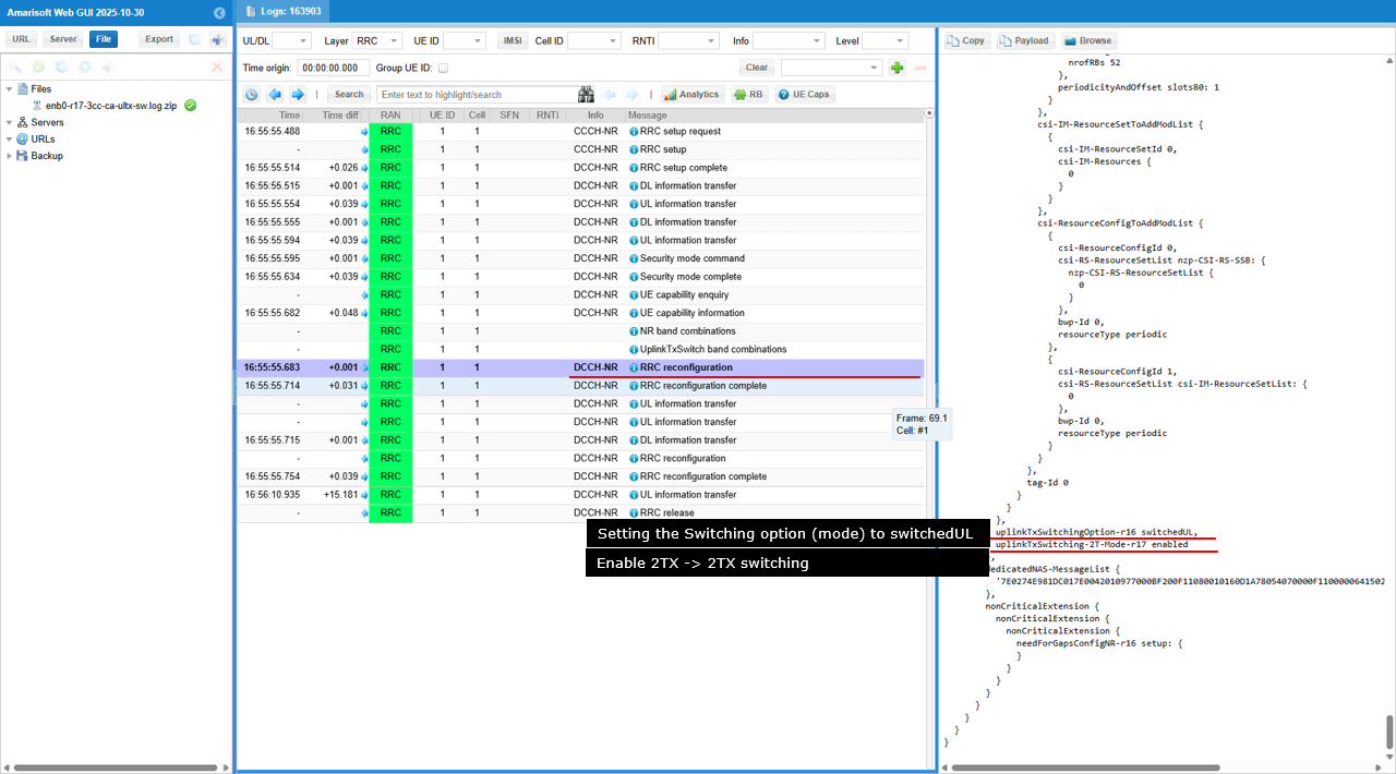
Then gNB specifies uplinkTxSwitchingOption ether to switchedUL or dualUL. In this test, gNB configured it to switchedUL and enable uplinkTxSwitching-2T-Mode..
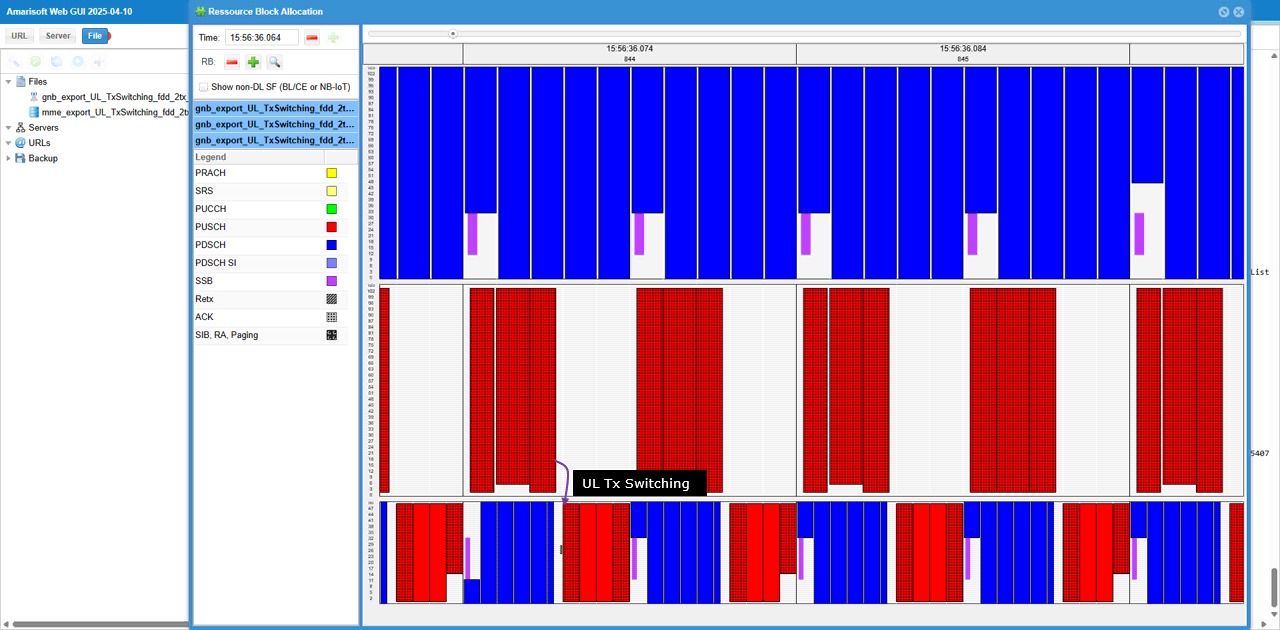
You can visually confirm how UL switching happens in RB Map plot.
Test 3 : 2TX -> 2TX Switching(One Cell -> Two Contiguous Cell), switchedUL (Rel 17)
This test is to test and show the concept of a simplest cases of UL Tx Switching. It is the case where (according to the scheduling by gNB) UE switches from 2Tx carrier to 2Tx carrier with switchedUL mode. In terms of the number of antenna involved in switching, this test is similar to previous test. But in this test, Carrier 2 consists of 2 contiguous cells with both cells having 2 layers whereas the carrier 2 consists of only one cell in previous test.
The specific scenation implemented in this test is illustrated as below
Configuration
I used the enb-ul-tx-switching-CA-rel17.cfg on gNB (
In enb-ul-tx-switching-CA-rel17.cfg, followings are configured.
First note that two antenna is configured for DL for both carriers (N_NR_ANTENNA_DL = 2) and for UL for both carriers (N_ANTENNA_UL = 2). In this test, N_ANTENNA_UL = 2 does not necessarily mean 2 layer(rank 2). The number of layer(max rank) will be specified to 1 or 2 depending on the situation. (
This configuration defines the first NR cell on rf_port: 0 and sets it up as an FDD cell (with subcarrier_spacing: 15 and ssb_subcarrier_spacing: 15). It then adds secondary cells for carrier aggregation using scell_list, and enables UL carrier aggregation on those SCells by setting ul_allowed: true. Finally, it enables NR UL TX switching for this cell with priority: 15, which assigns the UL Tx switching priority for the band (lower value means higher priority); in a 2-cell setup, priority: 15 corresponds to the carrier1 role, while priority: 0 corresponds to carrier2.
This second nr_cell_list entry configures a TDD NR cell on rf_port: 1 (with subcarrier_spacing: 30 and ssb_subcarrier_spacing: 30) and defines its TDD timing using tdd_ul_dl_config.pattern1 (e.g., dl_slots, dl_symbols, ul_slots, ul_symbols), because UL TX switching decisions matter on UL-capable slots/symbols. UL TX Switching is enabled with uplink_tx_switch.priority: 0, which gives this band the highest UL TX switching priority (and in a 2-cell setup corresponds to the “carrier2” role). The switching behavior is further controlled by uplink_tx_switch.activation (e.g., "ul_quality"), optionally constrained by uplink_tx_switch.preferred_option (e.g., "switchedUL"), and time-gated by uplink_tx_switch.active_slots, which acts like the carrier-specific slot mask (the equivalent of carrier2_slots) telling the scheduler which slots are eligible for UL scheduling on this carrier when switching is triggered.
In most of the use case, the max rank of carrier 2 is set to 2. The mode of UL Tx Activation is set to 'ulquality'. In this mode, UL Tx Switching happens based on the quality of UL channel. UL Tx Switching will be activated when the signal on carrier 2 (as measured by SRS) has an UL rank greater than 1 and an UL CQI above ul_quality_ri2_cqi_threshold
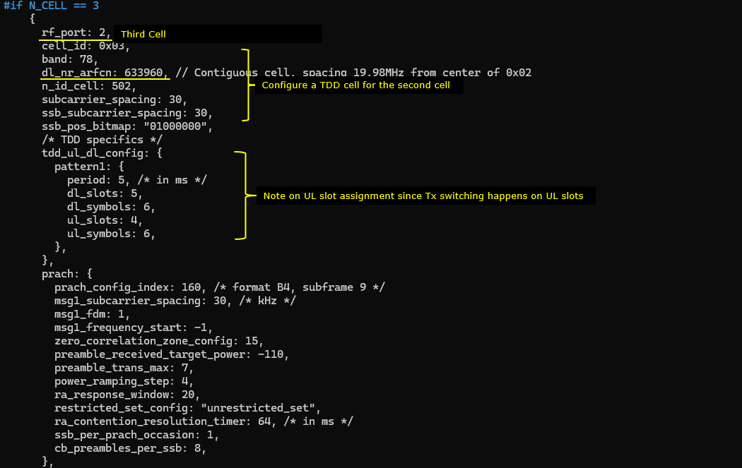
This optional third nr_cell_list entry (enabled by #if N_CELL == 3) adds another TDD n78 cell (band: 78, subcarrier_spacing: 30, ssb_subcarrier_spacing: 30) at dl_nr_arfcn: 633960, intended to be placed contiguously relative to the cell_id: 0x02 carrier. It defines the TDD UL/DL timing with tdd_ul_dl_config.pattern1 (dl_slots, dl_symbols, ul_slots, ul_symbols) so UL Tx switching can be applied only on UL-capable slots. UL Tx switching behavior is enabled through uplink_tx_switch.priority: 0 (highest priority / “carrier2” role in 2-cell terms), with activation controlled by uplink_tx_switch.activation: "ul_quality", a preference via uplink_tx_switch.preferred_option: "switchedUL", and slot eligibility constrained by uplink_tx_switch.active_slots: [0,0,0,0,0,0,0,0,1,1,1] (the carrier-specific slot mask used when deciding where UL can be scheduled under switching).
Perform the Test
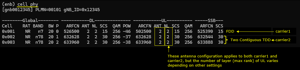
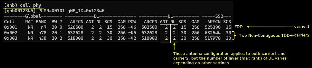
Check if the cell is configured as intended. Check out the output of 'cell phy' and cell command. 0x001 is an FDD n7 carrier identified as carrier1, and 0x002/0x003 are two contiguous TDD n78 carriers that form the carrier2 side. The ANT fields indicate the same antenna configuration is applied on both the carrier1 and carrier2 sides, while the effective UL spatial layers still depend on per-carrier UL settings such as pusch-Config.maxRank even though the RF/antenna setup is shared.
Now power on UE and wait until it completes attach and establishment of 3CC CA for both uplink and downlink.
Log Analysis
gNB sends UECapabilityEnquiry and includes ue-CapabilityEnquiryExt -> ue-CapabilityRequestFilterCommon -> uplinkTxSwitchRequest-r16: true. This means gNB explicitly requests UE to report UL Tx Switching (Rel-16) capability in the following UECapabilityInformation, so gNB can decide whether it can configure and use UL Tx switching for the UE (e.g., switched UL between the CA carriers).
This UE capability screen shows the UL Tx Switch band combinations that the UE can use for NR UL TX Switching. Under UL Tx Switch, Comb.1 indicates an inter-band pairing like DL N7A + UL N7A together with DL N78B + UL N78B, so UE can keep both carriers in the CA set but switch UL Tx between n7 and n78. Comb.2 indicates an intra-band pairing like DL N78A + UL N78A together with DL N78A + UL N78A, which matches the case of two contiguous n78 carriers, so UE can switch UL Tx between the two n78 UL legs based on gNB UL Tx switching control.
This UplinkTxSwitch band combinations report shows two UL Tx switching pairs under uplink_tx_switch.band_pairs. The first pair is band_1: 7 and band_2: 78, and the second pair is band_1: 78 and band_2: 78, so UE supports UL Tx switching for inter-band (n7↔n78) and intra-band (n78↔n78) CA cases. For both pairs, option: "switchedUL" means UE transmits UL on one carrier at a time and switches the UL Tx to the other carrier when needed, and twoT: true indicates UE supports the twoT-related UL Tx switching capability for these band pairs. The field release: 17 tells this capability set is reported as Rel-17.
This UE capability information shows an UL Tx switching capable PCC/SCC CA case under supportedBandCombinationList-uplinkTxSwitch-r16, where the band list includes bandNR: 7 (ClassDL a) and bandNR: 78 (ClassDL b) to represent an FDD–TDD inter-band combination, and it indicates the UE supports mixed numerology in this CA via diffNumerologyWithinPUCCH-GroupSmallerSCS: supported. The actual UL Tx switching pair is described in supportedBandPairListNR-r16 with bandIndexUL1-r16: 1 and bandIndexUL2-r16: 2, and the UE reports the required retuning gap with uplinkTxSwitchingPeriod-r16: n140us. Finally, uplinkTxSwitching-OptionSupport-r16: switchedUL confirms the UL Tx is performed on one carrier at a time, switching between the two UL legs rather than transmitting UL simultaneously.
This UE capability information shows a TDD–TDD SCC/SCC UL Tx switching band combination under supportedBandCombinationList-uplinkTxSwitch-r16, where the bandList contains bandNR: 78 twice, meaning the UE supports UL Tx switching between two n78 carriers in the same CA set. The actual UL switching pair is described in supportedBandPairListNR-r16 with bandIndexUL1-r16: 1 and bandIndexUL2-r16: 2, and the UE reports the required switching gap as uplinkTxSwitchingPeriod-r16: n140us. Finally, uplinkTxSwitching-OptionSupport-r16: switchedUL indicates the UE transmits UL on one of the two n78 carriers at a time and switches the UL transmitter between them when needed.
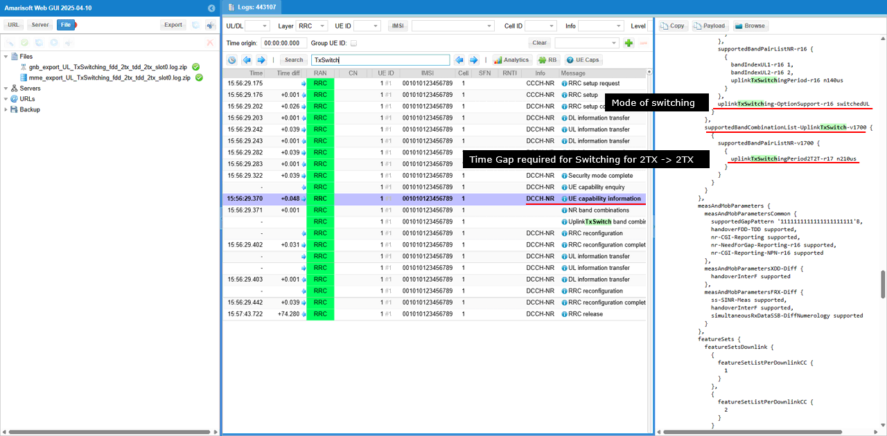
This part of UE capability information shows the Rel-17 UL Tx switching extension under supportedBandCombinationList-uplinkTxSwitch-v1700. In supportedBandPairListNR-v1700, UE reports uplinkTxSwitchingPeriod2T2T-r17: n210us, which is the required switching gap for the Rel-17 “2T2T” UL Tx switching case. This means gNB should use the Rel-17 switching period value (210 µs here) when it schedules UL and triggers UL Tx switching under the v1700 capability set.
This RRC reconfiguration sets pusch-Config.setup.maxRank: 2 for the PCC (carrier1). This means when UL Tx switching selects carrier1 for UL in a slot, UE can transmit PUSCH with up to 2 layers, so carrier1 is no longer limited to rank-1 UL and can use the same UL MIMO rank as the other UL leg if it is configured similarly.
This RRC reconfiguration adds the first SCC using sCellToAddModList with sCellIndex: 1, and it defines this SCC as a TDD n78 carrier by setting frequencyBandList: 78. This SCC becomes one UL leg that UL Tx switching can select for UL transmission when switchedUL operation is used.
This RRC reconfiguration sets pusch-Config.setup.maxRank: 2 for the SCC (carrier2). This means when UL Tx switching selects carrier2 for UL in a slot, UE can transmit PUSCH with up to 2 layers, so the scheduler can use rank-2 UL on this SCC while UL is switched onto it.
This RRC reconfiguration configures UL Tx switching for this cell by setting uplinkTxSwitching-r16.setup.uplinkTxSwitchingCarrier-r16: carrier2, so this cell is treated as the carrier2 leg in the UL Tx switching pair. It also sets uplinkTxSwitching-r16.setup.uplinkTxSwitchingPeriodLocation-r16: FALSE, so UE applies the UL switching gap with the FALSE placement rule(i.e, UE places the UL Tx switching gap on a specific side of the switch (typically absorbed on one carrier) instead of sharing the gap across both carriers around the boundary) when switching UL Tx to or from this carrier.
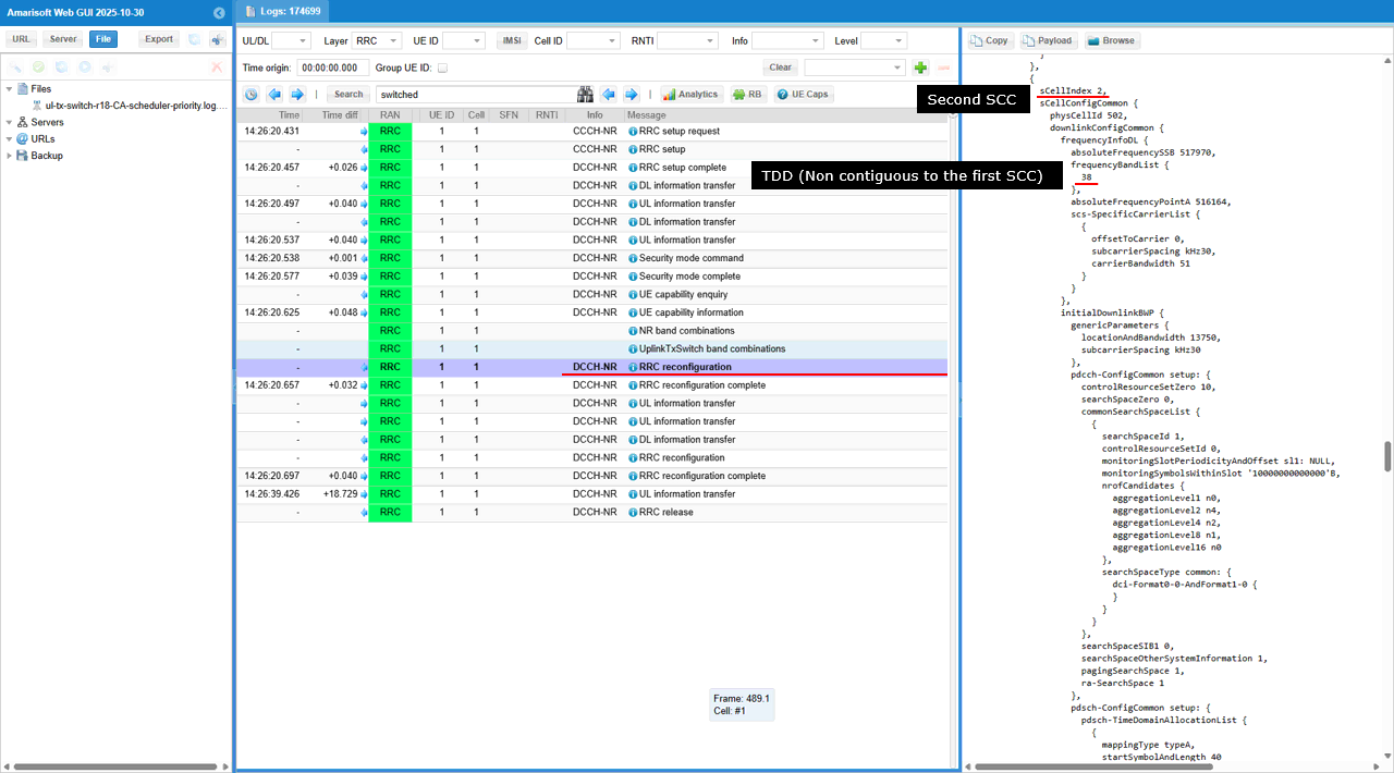
This RRC reconfiguration adds the second SCC using sCellToAddModList with sCellIndex: 2, and it defines it as another TDD n78 carrier by setting frequencyBandList: 78. Because it is configured as contiguous to the first SCC (same band and numerology via scs-SpecificCarrierList.subcarrierSpacing: kHz30 with its own absoluteFrequencyPointA), it forms the second n78 leg that UL Tx switching can switch to when switchedUL operation is used.
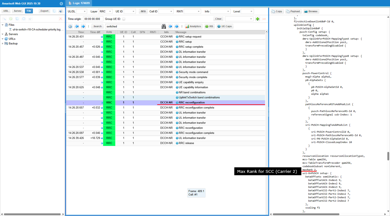
This RRC reconfiguration sets pusch-Config.setup.maxRank: 2 for the SCC on the carrier2 side. This means UE can transmit PUSCH with up to 2 layers when UL Tx switching selects this SCC for UL, so the scheduler can use rank-2 UL on this carrier during switched UL operation.
This RRC reconfiguration assigns this SCC as the UL Tx switching carrier2 by setting uplinkTxSwitching-r16.setup.uplinkTxSwitchingCarrier-r16: carrier2. It also sets uplinkTxSwitching-r16.setup.uplinkTxSwitchingPeriodLocation-r16: FALSE, so UE applies the switching gap with the FALSE placement rule when UL Tx is switched to or from this SCC.
uplinkTxSwitchingOption-r16: switchedUL tells UE to do UL Tx switching by transmitting UL on one carrier at a time and moving UL Tx to the other carrier when switching is triggered. uplinkTxSwitching2T-Mode-r17: enabled tells UE and gNB that 2T→2T switching is supported/activated, so the UL Tx switching operation can be done in the Rel-17 2T mode where the UE switches between carriers while keeping a 2-transmit-chain configuration.
This Resource Block Allocation view shows UL Tx switching operating with rank-2 UL on every selectable UL leg, because pusch-Config.maxRank: 2 is configured on the PCC and on the n78 SCCs, so the red PUSCH blocks appear as “2 layer” whichever carrier is selected by uplinkTxSwitchingOption-r16: switchedUL. The switching can happen between the two n78 SCC cells because they are configured as contiguous carriers, so the UE can retune and transmit on two SCC simultaneously using the same shared 2T antenna ports
Test 4 : 2TX -> 2TX Switching(One Cell -> Two Non Contiguous Cell), switchedUL (Rel 18)
This test is to test and show the concept of a simplest cases of UL Tx Switching. It is the case where (according to the scheduling by gNB) UE switches from 2Tx carrier to 2Tx carrier with switchedUL mode. In terms of the number of antenna involved in switching, this test is similar to previous test. But in this test, Carrier 2 consists of 2 non-contiguous cells with both cells having 2 layers whereas the carrier 2 consists of two contiguous cell in previous test.
The specific scenation implemented in this test is illustrated as below
Configuration
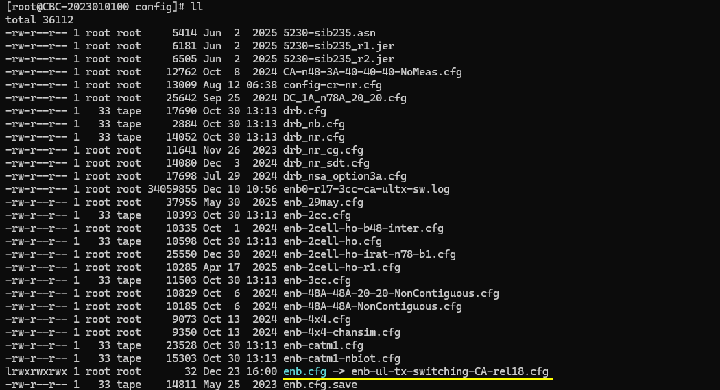
I used the enb-ul-tx-switching-CA-rel18-sched-priority.cfg on gNB (
In enb-ul-tx-switching-CA-rel18-sched-priority.cfg, followings are configured.
First note that two antenna is configured for DL for both carriers (N_NR_ANTENNA_DL = 2) and for UL for both carriers (N_ANTENNA_UL = 2). In this test, N_ANTENNA_UL = 2 does not necessarily mean 2 layer(rank 2). The number of layer(max rank) will be specified to 1 or 2 depending on the situation. (
This configuration defines the first NR cell on rf_port: 0 and sets it up as an FDD cell (with subcarrier_spacing: 15 and ssb_subcarrier_spacing: 15). It then adds secondary cells for carrier aggregation using scell_list, and enables UL carrier aggregation on those SCells by setting ul_allowed: true. Finally, it enables NR UL TX switching for this cell with priority: 15, which assigns the UL Tx switching priority for the band (lower value means higher priority); in a 2-cell setup, priority: 15 corresponds to the carrier1 role, while priority: 0 corresponds to carrier2.
This second nr_cell_list entry configures a TDD NR cell on rf_port: 1 (with subcarrier_spacing: 30 and ssb_subcarrier_spacing: 30) and defines its TDD timing using tdd_ul_dl_config.pattern1 (e.g., dl_slots, dl_symbols, ul_slots, ul_symbols), because UL TX switching decisions matter on UL-capable slots/symbols. UL TX Switching is enabled with uplink_tx_switch.priority: 0, which gives this band the highest UL TX switching priority (and in a 2-cell setup corresponds to the “carrier2” role). The switching behavior is further controlled by uplink_tx_switch.activation (e.g., "ul_quality"), optionally constrained by uplink_tx_switch.preferred_option (e.g., "switchedUL"), and time-gated by uplink_tx_switch.active_slots, which acts like the carrier-specific slot mask (the equivalent of carrier2_slots) telling the scheduler which slots are eligible for UL scheduling on this carrier when switching is triggered.
In most of the use case, the max rank of carrier 2 is set to 2. The mode of UL Tx Activation is set to 'ulquality'. In this mode, UL Tx Switching happens based on the quality of UL channel. UL Tx Switching will be activated when the signal on carrier 2 (as measured by SRS) has an UL rank greater than 1 and an UL CQI above ul_quality_ri2_cqi_threshold
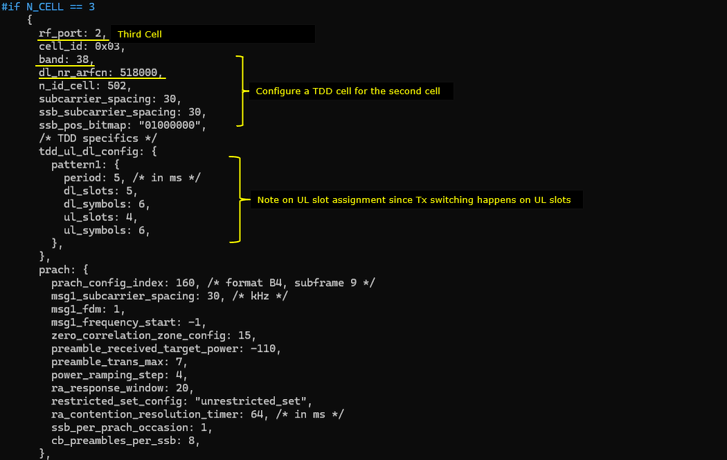
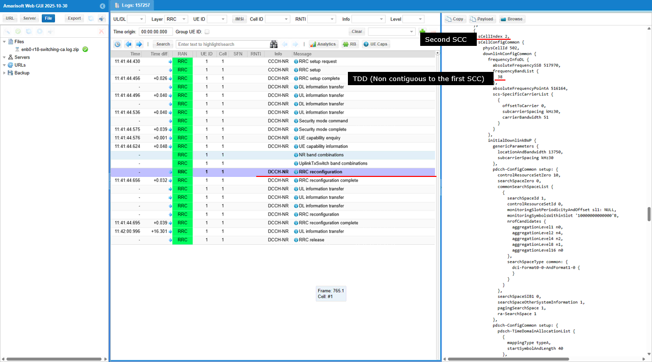
This optional third nr_cell_list entry (enabled by #if N_CELL == 3) adds another TDD n38 cell (band: 38, subcarrier_spacing: 30, ssb_subcarrier_spacing: 30) at dl_nr_arfcn: 518000, intended to be placed contiguously relative to the cell_id: 0x02 carrier. It defines the TDD UL/DL timing with tdd_ul_dl_config.pattern1 (dl_slots, dl_symbols, ul_slots, ul_symbols) so UL Tx switching can be applied only on UL-capable slots. UL Tx switching behavior is enabled through uplink_tx_switch.priority: 0 (highest priority / “carrier2” role in 2-cell terms), with activation controlled by uplink_tx_switch.activation: "ul_quality", a preference via uplink_tx_switch.preferred_option: "switchedUL", and slot eligibility constrained by uplink_tx_switch.active_slots: [0,0,0,0,0,0,0,1,1,0,0] (the carrier-specific slot mask used when deciding where UL can be scheduled under switching).
Perform the Test
Check if the cell is configured as intended. Check out the output of 'cell phy' and cell command. 0x001 is an FDD n7 carrier identified as carrier1, and 0x002/0x003 are two contiguous TDD n78 carriers that form the carrier2 side. The ANT fields indicate the same antenna configuration is applied on both the carrier1 and carrier2 sides, while the effective UL spatial layers still depend on per-carrier UL settings such as pusch-Config.maxRank even though the RF/antenna setup is shared.
Now power on UE and wait until it completes attach and establishment of 3CC CA for both uplink and downlink.
Log Analysis
This UE capability enquiry includes capabilityRequestFilterCommon.uplinkTxSwitchRequest-r16: true, so the gNB is explicitly requesting the UE to report UL Tx switching (Rel-16) related capabilities (i.e., the UE’s supported supportedBandCombinationList-uplinkTxSwitch-*, switching option like switchedUL, and switching timing such as uplinkTxSwitchingPeriod-r16).
This UE capability view shows the UE has an UL Tx Switch band combination where the CA set includes n7 + n38 + n78, and UL can be switched so that only one UL leg is active at a time across those carriers (shown by the UL Tx Switch → Comb. 1 entry listing DL N7A + UL N7A | DL N38A + UL N38A | DL N78A + UL N78A).
This log shows the UE reports uplink_tx_switch with band_pairs = (n7,n38), (n7,n78), (n38,n78), and for each pair it supports option: "switchedUL" with twoTx: true, meaning the UE can do UL Tx switching between those carrier pairs while keeping 2-TX capability available (Rel-18).
This shows that the UE supports a CA band-combination that can be used for UL Tx switching (the combination lists n7 / n38 / n78 entries), and it also reports the Rel-16 switching requirement under supportedBandPairListNR-r16, where bandIndexUL1-r16 = 1 and bandIndexUL2-r16 = 2 form the UL band pair and uplinkTxSwitchingPeriod-r16 = n140us indicates the UE needs a 140 µs retune gap when switching the uplink transmitter between those two UL band indices.
This log shows that the UE reports UL Tx Switching capability across releases. For r16, the UE declares the switching time gap (for example 140 µs) that is needed while the UE retunes its single UL transmitter between carriers. For r17, the UE reports an updated switching-period set (for example 210 µs), meaning the gNB can schedule UL switching using the r17 timing rule when it selects that feature set. For r18, the UE reports more detailed switching options per band-pair, including the switching mode (e.g., switchedUL) and separate switching-period values for band-pair / FDD / TDD cases, so the gNB can apply the right gap depending on which two carriers are being switched. This is why UL Tx switching can still be exercised even with three non-contiguous cells: the key requirement is “UE supports those band-pairs and timing rules”, not “cells must be contiguous”.
In this RRCReconfiguration, gNB sets pusch-Config for the PCC (carrier1) and the highlighted maxRank 2 means the UE is allowed to use up to 2 UL layers (rank-2 UL MIMO) on PUSCH when the UL transmission is on this carrier.
In this RRCReconfiguration, gNB sends scellToAddModList to add the first SCC (scellIndex = 1), and frequencyBandList = n78 with TDD means this SCC is a TDD NR carrier with its own DL/SSB frequency parameters (e.g., absoluteFrequencySSB/PointA and SCS-specific carrier list). In the UL Tx switching context, this SCC becomes one of the UL candidate carriers, so the UE can switch the UL transmitter between the PCC and this SCC (or between SCCs) using the configured switching option and gap, while still transmitting UL on only one carrier at a time with the shared antenna/RF chain.
In this RRCReconfiguration, gNB configures PUSCH for SCC (carrier2) and sets maxRank = 2, meaning that when UL Tx switching selects this SCC as the active UL carrier, the UE may transmit up to 2 spatial layers on that SCC (subject to the UE capability and the current switching/gap constraints), even though only one UL carrier is used at a time during switching.
In this RRCReconfiguration, gNB adds Second SCC (sCellIndex=2) as a TDD NR carrier in band n38 (with its own absoluteFrequencySSB/PointA), and because this SCC is not contiguous to the first SCC, any UL Tx switching between the SCCs means the UE must retune RF and use a switching gap, so the UE can only transmit UL on one carrier at a time and the switching timing/gap parameters decide when that move is allowed.
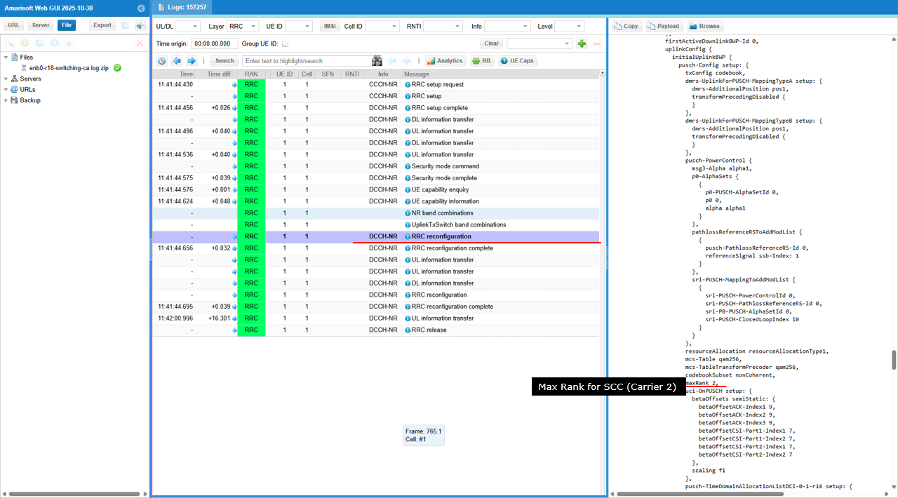
This RRCReconfiguration sets maxRank = 2 for the SCC (Carrier 2), meaning the UE can use up to 2 UL layers when it transmits on that carrier. This becomes relevant with UL Tx switching because when the UE switches its UL transmission from another carrier to Carrier 2, the UL transmission on Carrier 2 will follow this 2-layer cap
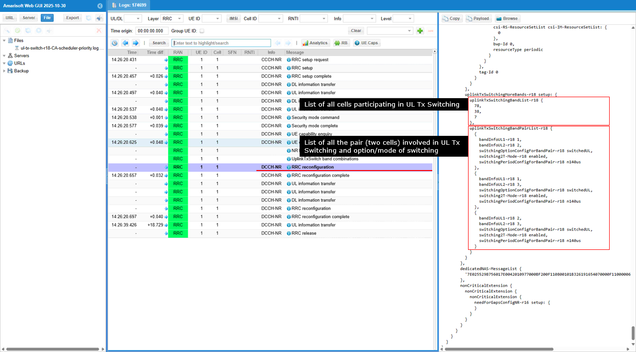
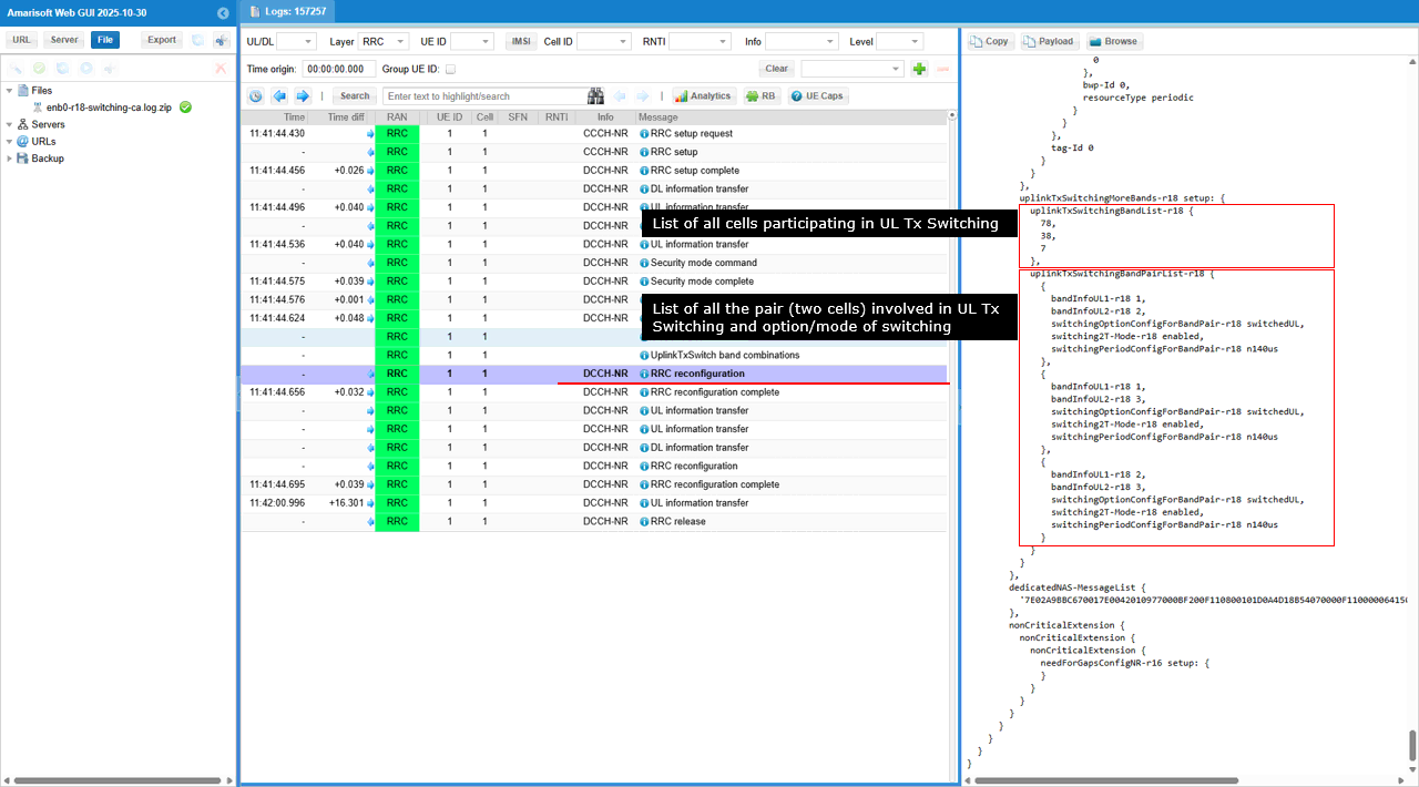
This UE Capability Information shows uplinkTxSwitchingMoreBands-r18 is configured, so the UE can do UL Tx switching across more than two bands. uplinkTxSwitchingBandList-r18 lists the participating bands as n7, n38, and n78, which matches the test setup with three non-contiguous cells. uplinkTxSwitchingBandPairList-r18 then enumerates the supported pairs (index 1–2, 1–3, 2–3), so the UE can switch UL between any two of n7/n38/n78. For each pair, switchingOptionConfigForBandPair-r18 = switchedUL means the UL is time-switched (one band at a time), switching2T-Mode-r18 = enabled means 2TX → 2TX switching is supported, and switchingPeriodConfigForBandPair-r18 = n140us means the UE needs a 140 µs switching gap during retuning.
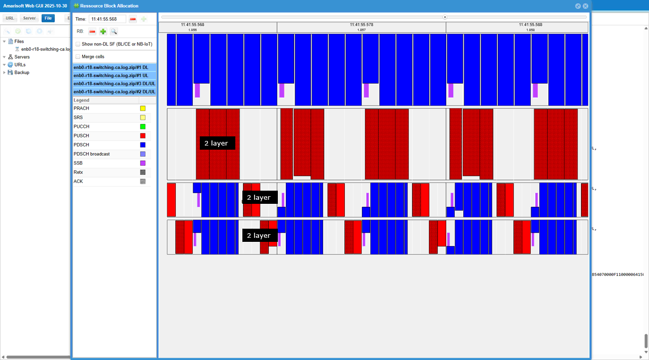
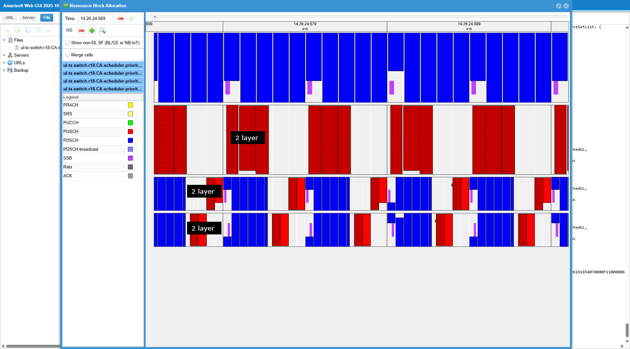
This Resource Block Allocation view shows the gNB scheduling UL with UL Tx switching (switchedUL) across three three non-contiguous cells (n7/n38/n78). You can see PUSCH (red) appearing on one cell, then moving to another cell in the next available UL opportunity, so only one band/cell is actively transmitting UL at a time. The “2 layer” labels indicate the UE is using rank-2 UL on the currently selected cell, which is consistent with 2TX → 2TX switching enabled.
Test 5 : 2TX -> 2TX Switching(One Cell -> Two Non Contiguous Cell), switchedUL, User Defined Switching Point (Rel 18)
This test is to test and show the concept of a simplest cases of UL Tx Switching. It is the case where (according to the scheduling by gNB) UE switches from 2Tx carrier to 2Tx carrier with switchedUL mode. In terms of the number of antenna involved in switching and band combination, this test is similar to previous test. But in this test, the switching point is defined by user via configuration file whereas the switching point is determined by gNB in previous test.
The specific scenation implemented in this test is illustrated as below
Configuration
I used the enb-ul-tx-switching-CA-rel18.cfg on gNB (
In enb-ul-tx-switching-CA-rel18.cfg , followings are configured.
First note that two antenna is configured for DL for both carriers (N_NR_ANTENNA_DL = 2) and for UL for both carriers (N_ANTENNA_UL = 2). In this test, N_ANTENNA_UL = 2 does not necessarily mean 2 layer(rank 2). The number of layer(max rank) will be specified to 1 or 2 depending on the situation. (
This configuration defines the first NR cell on rf_port: 0 and sets it up as an FDD cell (with subcarrier_spacing: 15 and ssb_subcarrier_spacing: 15). It then adds secondary cells for carrier aggregation using scell_list, and enables UL carrier aggregation on those SCells by setting ul_allowed: true. Finally, it enables NR UL TX switching for this cell with priority: 15, which assigns the UL Tx switching priority for the band (lower value means higher priority); in a 2-cell setup, priority: 15 corresponds to the carrier1 role, while priority: 0 corresponds to carrier2.
This second nr_cell_list entry configures a TDD NR cell on rf_port: 1 (with subcarrier_spacing: 30 and ssb_subcarrier_spacing: 30) and defines its TDD timing using tdd_ul_dl_config.pattern1 (e.g., dl_slots, dl_symbols, ul_slots, ul_symbols), because UL TX switching decisions matter on UL-capable slots/symbols. UL TX Switching is enabled with uplink_tx_switch.priority: 0, which gives this band the highest UL TX switching priority (and in a 2-cell setup corresponds to the “carrier2” role). The switching behavior is further controlled by uplink_tx_switch.activation (e.g., "ul_quality"), optionally constrained by uplink_tx_switch.preferred_option (e.g., "switchedUL"), and time-gated by uplink_tx_switch.active_slots, which acts like the carrier-specific slot mask (the equivalent of carrier2_slots) telling the scheduler which slots are eligible for UL scheduling on this carrier when switching is triggered.
In most of the use case, the max rank of carrier 2 is set to 2. The mode of UL Tx Activation is set to 'ulquality'. In this mode, UL Tx Switching happens based on the quality of UL channel. UL Tx Switching will be activated when the signal on carrier 2 (as measured by SRS) has an UL rank greater than 1 and an UL CQI above ul_quality_ri2_cqi_threshold
This optional third nr_cell_list entry (enabled by #if N_CELL == 3) adds another TDD n38 cell (band: 38, subcarrier_spacing: 30, ssb_subcarrier_spacing: 30) at dl_nr_arfcn: 518000, intended to be placed contiguously relative to the cell_id: 0x02 carrier. It defines the TDD UL/DL timing with tdd_ul_dl_config.pattern1 (dl_slots, dl_symbols, ul_slots, ul_symbols) so UL Tx switching can be applied only on UL-capable slots. UL Tx switching behavior is enabled through uplink_tx_switch.priority: 0 (highest priority / “carrier2” role in 2-cell terms), with activation controlled by uplink_tx_switch.activation: "ul_quality", a preference via uplink_tx_switch.preferred_option: "switchedUL", and slot eligibility constrained by uplink_tx_switch.active_slots: [0,0,0,0,0,0,0,1,1,0,0] (the carrier-specific slot mask used when deciding where UL can be scheduled under switching).
Perform the Test
Check if the cell is configured as intended. Check out the output of 'cell phy' and cell command. 0x001 is an FDD n7 carrier identified as carrier1, and 0x002/0x003 are two contiguous TDD n78 carriers that form the carrier2 side. The ANT fields indicate the same antenna configuration is applied on both the carrier1 and carrier2 sides, while the effective UL spatial layers still depend on per-carrier UL settings such as pusch-Config.maxRank even though the RF/antenna setup is shared.
Now power on UE and wait until it completes attach and establishment of 3CC CA for both uplink and downlink.
Log Analysis
This UE capability enquiry includes capabilityRequestFilterCommon.uplinkTxSwitchRequest-r16: true, so the gNB is explicitly requesting the UE to report UL Tx switching (Rel-16) related capabilities (i.e., the UE’s supported supportedBandCombinationList-uplinkTxSwitch-*, switching option like switchedUL, and switching timing such as uplinkTxSwitchingPeriod-r16).
This UE capability screen is saying the UE supports UL Tx Switching for the specific 3CC set n7 + n38 + n78 (shown as DL N7A + UL N7A, DL N38A + UL N38A, DL N78A + UL N78A), meaning the UE can keep the three DL carriers aggregated, but for uplink it will select one of these cells at a time and switch (“switchedUL”) the same Tx chain(s) between the three bands when the scheduler requests UL on a different cell, with a small switching gap/period rather than doing simultaneous UL on all three.
This “UplinkTxSwitch band combinations” block is the UE explicitly telling the gNB that for the 3-band set (n7, n38, n78) it supports UL Tx switching pair-by-pair between 7↔38, 7↔78, and 38↔78, and that for each pair the switching mode is switchedUL with twoT: true (meaning the UE can do the switching while using two TX chains / up to 2 UL layers, i.e., 2Tx → 2Tx switching), and it reports this capability as Release 18 so the scheduler is allowed to move UL between those cells (even if your three cells are non-contiguous in frequency, the capability here is about supported band pairs + switching mode, while any “shared antenna / contiguity” constraint is a separate RF implementation detail).
The highlighted supportedBandCombinationList-uplinkTxSwitch-r16 is the UE’s declaration that UL Tx switching is supported for the NR band-combination set {n7, n38, n78} (each with ca-BandwidthClassDL-NR a and ca-BandwidthClassUL-NR a), along with the related capability details like featureSetCombination 9 and ca-ParametersNR (for example simultaneousRxTxInterBandCA supported and mixed-numerology support), and when you combine that with the separate “UplinkTxSwitch band combinations” list (the allowed band pairs plus option = switchedUL and twoT = true) and the release-specific switching gaps/periods (Rel-16/17/18), it explains why this test with three non-contiguous cells still works: the UE cannot UL-transmit on all three at the same time, so the scheduler time-shares the UE’s two Tx chains and alternates UL between the supported band pairs
The highlighted IEs show that the UE reports Uplink Tx Switching capability across multiple releases: supportedBandPairListNR-r16 indicates the Rel-16 baseline with uplinkTxSwitchingPeriod-r16 = n140us, supportedBandCombinationList-UplinkTxSwitch-v1700 adds Rel-17 2Tx→2Tx behavior with uplinkTxSwitchingPeriod2T2T-r17 = n210us, and supportedBandCombinationList-UplinkTxSwitch-v1800 provides the Rel-18 detailed control where switchingOptionConfigForBandPair-r18 = switchedUL and the UE can signal different switching times (e.g., 140 µs vs 210 µs) depending on the switching scenario so the gNB can schedule UL Tx Switching more precisely.
In this RRC reconfiguration message, the UE (and gNB config) sets maxRank = 2 under pusch-Config for the PCC (Carrier 1), which means the uplink on this carrier is allowed to use up to 2 layers (2Tx UL MIMO); in the UL Tx Switching context, this effectively says “when the UE’s transmit chain is assigned to the PCC as the active UL carrier during switching, it can transmit with rank-2,” while the other configured cells may have their own maxRank values for when they become the active UL carrier.
In this RRC reconfiguration, the gNB adds the first SCC via sCellToAddModList (with sCellIndex = 1), where sCellConfigCommon shows physCellId = 501 and downlinkConfigCommon.frequencyInfoDL.frequencyBandList indicates NR band 78 (TDD), with absoluteFrequencySSB = 632544, absoluteFrequencyPointA = 632016, and scs-SpecificCarrierList set to subcarrierSpacing = kHz30 and carrierBandwidth = 51—this SCC is therefore one of the CA cells that participates in your UL Tx switching setup, meaning the UE can keep this SCC for DL reception while UL transmission capability is managed by the negotiated UL Tx switching rules (i.e., the TX chain is switched/borrowed across the configured band pair(s) rather than requiring a dedicated UL chain on every SCC).
In this RRC reconfiguration, the UL configuration for the SCC (treated as “carrier2” in the UL Tx Switching setup) includes the IE maxRank = 2, which means when UL Tx Switching temporarily enables uplink on this SCC, the UE can transmit up to rank-2 (2 layers) PUSCH on that switched carrier.
This sCellToAddModList entry with sCellIndex = 2 defines the second SCC as a TDD carrier on NR band frequencyBandList = 38 using its own downlink frequency settings under downlinkConfigCommon.frequencyInfoDL (notably absoluteFrequencySSB, absoluteFrequencyPointA, and the scs-SpecificCarrierList with offsetToCarrier, subcarrierSpacing, carrierBandwidth), and because this SCC is non-contiguous to the first SCC, any UL Tx Switching enabled by IEs like uplinkTxSwitchingBandList(-r18) / uplinkTxSwitchingBandPairList(-r18) with uplinkTxSwitchingOptionConfigForBandPair = switchedUL will be handled as time-switched UL on one selected band-pair at a time (retuning the shared TX chain), rather than “sharing” a wide RF path to do simultaneous 2Tx across adjacent SCCs.
In this RRCReconfiguration, the IE maxRank (shown as maxRank 2 inside the SCC’s uplinkConfig / pusch-Config) means this SCC (Carrier 2) is allowed to use up to Rank-2 UL transmission (two UL layers / 2Tx UL-MIMO), and in UL Tx Switching terms it tells the gNB that when the UE switches its uplink transmitter onto this carrier, it can operate in a 2Tx mode, so the scheduler can apply the appropriate switching gap depending on whether the switch is 1T↔1T or 2T↔2T.
This UECapabilityInformation shows the Rel-18 UL Tx Switching IEs where uplinkTxSwitchingBandList-r18 lists all bands/cells that can participate in UL Tx Switching (here 7/38/78), and uplinkTxSwitchingBandPairList-r18 then defines the allowed switching pairs using bandInfoUL1-r18 and bandInfoUL2-r18, while also telling the gNB the switching behavior via switchingOptionConfigForBandPair-r18 = switchedUL, switching2T-mode-r18 = enabled (2Tx↔2Tx capable), and the required gap via switchingPeriodConfigForBandPair-r18 (here shown as n140us for each listed pair).
This Resource Block Allocation view shows that, even though you configured three non-contiguous cells (so the UE cannot keep simultaneous UL on all of them), the scheduler is using UL Tx Switching to time-share the same UL transmitter(s) across the configured carriers, and when the UE is on a given UL carrier it can still transmit rank-2 PUSCH (the red blocks marked “2 layer”, meaning 2 UL layers / 2Tx mode) before switching the UL to another carrier in a different time segment.