NR SA SRS : Carrier Switch
The purpose of this tutorial is to show you how to test SRS Carrier Switching in NR SA. In this tutorial, it is assumed that you are faimiliar with basic operations of Amari Callbox operation. So in this tutorial, I will explain only about the configuration and analyzing the test result in the WebGUI log.
NR SRS carrier switching lets a UE transmit SRS on an uplink carrier even when it does not have a concurrent PUSCH configured on that carrier. This is mainly used so the gNB can obtain CSI via TDD reciprocity, which is important for beamforming and massive MIMO. The UE briefly retunes its transmitter from the primary uplink carrier to a target carrier only for SRS, so the network can characterize multiple bands with limited RF resources.
Table of Contents
Introduction
Sounding Reference Signal (SRS) carrier switching is a critical feature in 5G New Radio Standalone (NR SA) networks, designed to enhance uplink channel state information (CSI) acquisition for advanced radio technologies such as beamforming and massive MIMO. In NR architectures, SRS enables the User Equipment (UE) to transmit uplink reference signals on specific carriers, allowing the gNB (next-generation NodeB) to analyze and optimize the radio environment across multiple frequency bands. SRS carrier switching extends this capability by allowing the UE to send SRS on a secondary or target uplink carrier, even when it does not have a simultaneous Physical Uplink Shared Channel (PUSCH) allocation on that carrier. This mechanism is particularly valuable in Time Division Duplex (TDD) deployments, where channel reciprocity is leveraged for more efficient CSI estimation. The UE temporarily retunes its transmitter from its primary uplink carrier to the designated target carrier solely to transmit SRS, thereby enabling the network to perform channel measurements and beam management across wider or multiple frequency bands without requiring additional RF chains or continuous uplink traffic. This tutorial will provide an in-depth guide to configuring and evaluating SRS carrier switching scenarios using the Amari Callbox, focusing on the practical aspects of setup and log analysis through the WebGUI, while assuming a foundational knowledge of general Amari Callbox operation and NR test principles.
-
Context and Background
- SRS carrier switching is integral to 5G NR SA networks for advanced uplink channel probing and CSI collection, supporting key features like beamforming and massive MIMO.
- The Amari Callbox platform provides a controlled environment for testing NR features, enabling users to configure complex scenarios and analyze UE and network behavior through detailed logs.
- The tutorial is designed for users already acquainted with the basics of Amari Callbox operations and general NR testing methodologies.
-
Relevance and Importance
- Mastering SRS carrier switching is essential for R&D engineers and test specialists involved in 5G NR feature verification, particularly in scenarios that demand high-precision CSI for dynamic spectrum and beam management.
- Understanding how to configure and interpret SRS carrier switching events aids in optimizing network performance, validating device compliance, and supporting interoperability testing across multi-band deployments.
-
Learning Outcomes
- Gain practical knowledge on configuring SRS carrier switching using the Amari Callbox WebGUI.
- Develop the ability to analyze test results and logs to verify correct SRS carrier switching behavior.
- Understand the underlying principles and architectural mechanisms that enable SRS carrier switching in NR SA.
-
Prerequisite Knowledge
- Familiarity with the basic operation of the Amari Callbox, including general configuration and log analysis.
- Understanding of 5G NR SA concepts, uplink reference signals, and general RF testing methodologies.
- Basic knowledge of WebGUI navigation and interpreting protocol-level test logs.
Summary of the Tutorial
This tutorial provides step-by-step procedures for testing SRS (Sounding Reference Signal) carrier switching in 5G NR Standalone (SA) mode using Amarisoft software. The focus is on verifying that SRS transmission can be switched across multiple downlink carriers while uplink user data remains on the primary carrier. Two main test scenarios are covered: SRS carrier switching with 2CC (Component Carriers) and with 3CC, both without uplink carrier aggregation.
-
Test Setup Overview
- The test uses a SIM card delivered with the system and a simple low-layer setup. If configuration changes are required, refer to the Configuration Guide.
-
Key Configuration Parameters
- Critical SRS-related parameters are highlighted, such as srs_symbols, srs_resource (including srs_resource_id, n_ports, transmission_comb, cyclic_shift, etc.), srs_resource_set (including srs_resource_set_id, srs_resource_id_list, aperiodic_srs_trigger, etc.), and srs_carrier_switching.
- These parameters control the periodicity, antenna port usage, and resource allocation for SRS transmission and switching across carriers.
-
Test 1: 1 SRS Carrier Switching with 2CC DL CA/no UL CA
-
Procedure:
- Use the gnb-2cc-sa-srs-sw.cfg configuration file to enable SRS carrier switching and periodic SRS transmission.
- Set NR_TDD=1 for TDD operation, pick the desired TDD configuration and bandwidth, and enable 2x2 MIMO for downlink.
- Configure the primary cell (PCC) and a single secondary cell (SCC) for downlink CA. No uplink CA is configured.
- Enable SRS resource sets for both codebook-based and antenna switching usage, and activate srs_carrier_switching:true and srs_switching_time_request:true.
- Configure the nr_cell_default block for global cell settings, including DL/UL slot allocation and maximum uplink MIMO rank.
-
Test Execution:
- Perform a standard NR SA attach sequence using the configured gNB.
- After attach, verify via logs that the UE transmits SRS as configured on both the PCC and SCC, while uplink data (PUSCH) remains on the PCC.
-
Log Analysis:
- Confirm that the gNB explicitly requests SRS switching capability from the UE and configures SRS resource sets for both codebook and antenna switching.
- Verify in the resource block allocation view that SRS bursts appear on both PCC and SCC at expected intervals, with uplink data scheduled only on the PCC.
-
Procedure:
-
Test 2: SRS Carrier Switching with 3CC DL CA/no UL CA
-
Procedure:
- Use the gnb-3cc-sa-srs-sw.cfg configuration file to enable SRS carrier switching and periodic SRS transmission across three cells.
- Configure the primary cell (PCC) and two secondary cells (SCCs) for downlink CA, each with its own frequency and cell ID. No uplink CA is configured.
- Enable SRS resource sets for antenna switching on all three cells and activate srs_carrier_switching:true and srs_switching_time_request:true in each cell's SRS block.
- Set cell-wide parameters for bandwidth, antenna configuration, and TDD UL/DL slot allocation.
-
Test Execution:
- Perform the NR SA attach procedure as in Test 1.
- Verify that the UE transmits SRS on the PCC and both SCCs, while uplink data (PUSCH) remains on the PCC.
-
Log Analysis:
- Confirm SRS switching is requested and configured for all three carriers via log inspection.
- Check the resource block allocation view to ensure SRS transmissions are present on all three carriers, but PUSCH is only present on the PCC.
-
Procedure:
-
General Methodology Notes
- For both tests, the test process primarily consists of setting up the correct configuration, performing an NR SA attach, and then verifying correct SRS behavior through log and resource block allocation analysis.
- Key indicators of successful test execution are the correct presence of SRS on all targeted carriers and the restriction of uplink user data to the PCC.
By following these procedures, users can validate SRS carrier switching functionality in a controlled test environment, ensuring that SRS is properly transmitted across multiple carriers as required by the configured test scenarios.
Test Setup
Test setup for this tutorial is as shown below. This is just for low layer testing, you may not need any complicated IP layer setup.
- SIM Card used in this tutorial is the one delivered with the system as it is.
- If you want to change the configuration, The tutorial Configuration Guide would help

Key Configuration Parameters
Followings are important configuration parameters for this tutorial. You may click on the items for the descriptions from Amarisoft documents.
- srs : In this link, you can get the descriptions for all the parameters listed below
- srs_symbols
- srs_resource
- srs_resource_id
- n_ports
- transmission_comb
- cyclic_shift
- n_symb
- repetition_factor
- c_srs
- freq_domain_shift
- b_srs
- b_hop
- group_or_sequence_hopping
- n_id
- resource_type
- period
- srs_resource_set
- srs_carrier_switching
- srs_switching_time_request
Test 1 : 1 SRS Carrier Switching with 2CC DL CA/no UL CA
The purpose of this test is to demonstrate how to configure and verify SRS carrier switching, by applying the RRC configuration that enables SRS switching and then confirming in the logs/RB allocation view that the UE transmits SRS on both PCC and SCC while uplink data (PUSCH) remains on the PCC
Configuration
I have used gnb-2cc-sa-srs-sw.cfg

I am using the default mme, ims config as shown below.

In gnb-2cc-sa-srs-sw.cfg , it is configured as follows.
In this configuration, NR_TDD=1 enables NR TDD (not FDD) and the active FR1 settings are NR_TDD_CONFIG=2 (FR1 TDD configuration index) and NR_BANDWIDTH=40 (cell bandwidth). it then defines the RF port configuration with N_ANTENNA_DL=2 for 2x2 MIMO downlink, and finally enables uplink sounding by setting SRS_SW=1 to activate srs_carrier_switching and USE_SRS=1 to enable periodic SRS transmission using the configured uplink antenna ports.

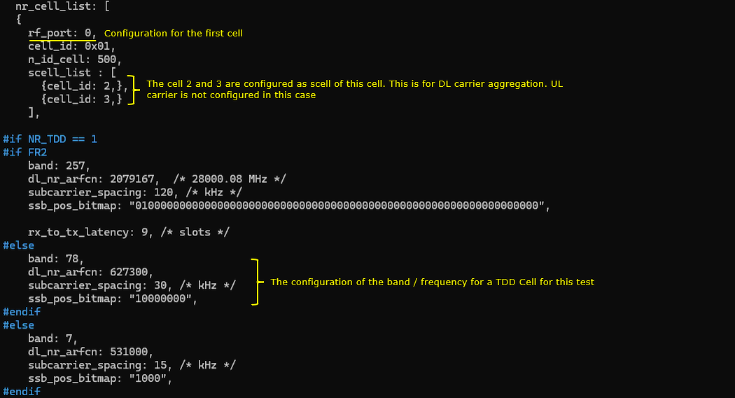
In this configuration, nr_cell_list defines the first NR cell on rf_port=0 with cell_id=0x01 and n_id_cell=500, and it also sets scell_list with {cell_id: 2} so cell 2 is configured as the SCell of this cell for downlink carrier aggregation, while uplink CA is not configured in this case. Since NR_TDD==1, the band and frequency for this TDD cell are configured with band=78, dl_nr_arfcn=627300, subcarrier_spacing=30 kHz, and ssb_pos_bitmap="10000000", which defines the operating frequency, numerology, and the enabled SSB position pattern for this test.
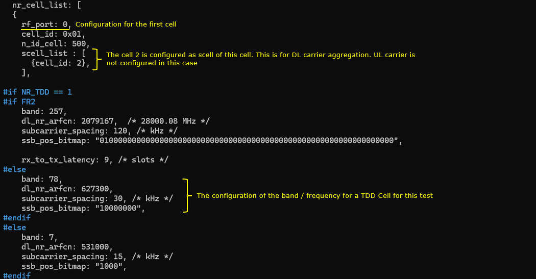
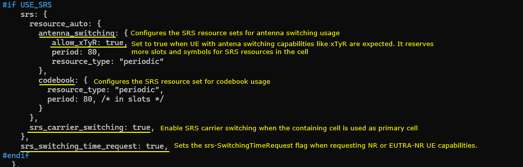
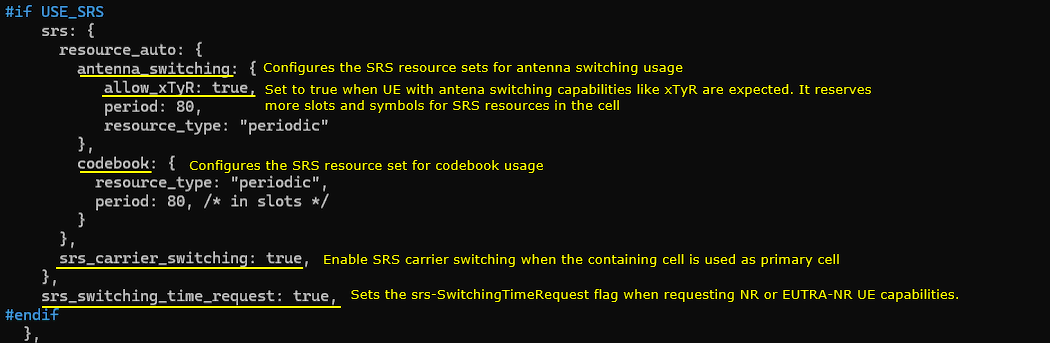
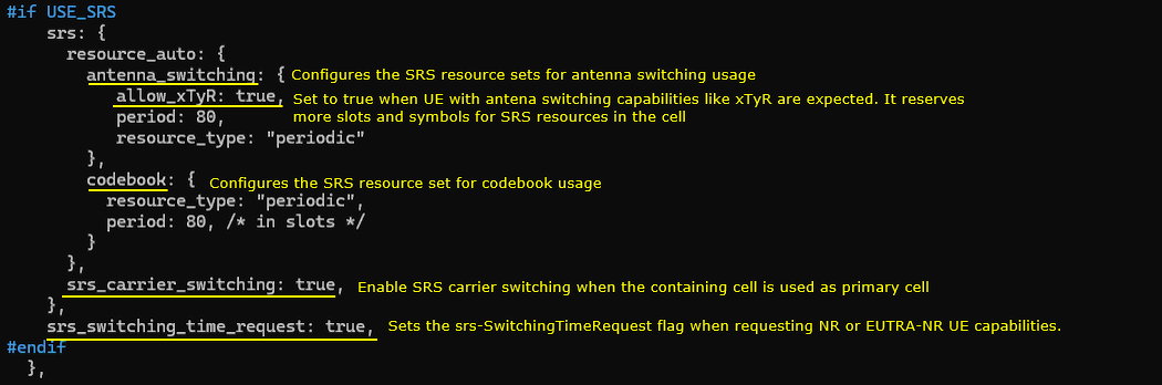
In this configuration, #if USE_SRS enables the srs block and uses resource_auto to create periodic SRS resources for two purposes, where antenna_switching is used to configure SRS resource sets for antenna switching operation and allow_xTyR:true tells the cell to expect UEs with antenna switching capability (like xTxR) so it reserves additional slots and symbols for SRS; it also defines a separate codebook resource set with resource_type:"periodic" and period:80 slots for codebook-based sounding, then sets srs_carrier_switching:true to enable SRS carrier switching when this cell is used as the primary cell, and finally sets srs_switching_time_request:true so the gNB/eNB can include the srs-SwitchingTimeRequest indication when requesting NR or EUTRA-NR UE capability information.
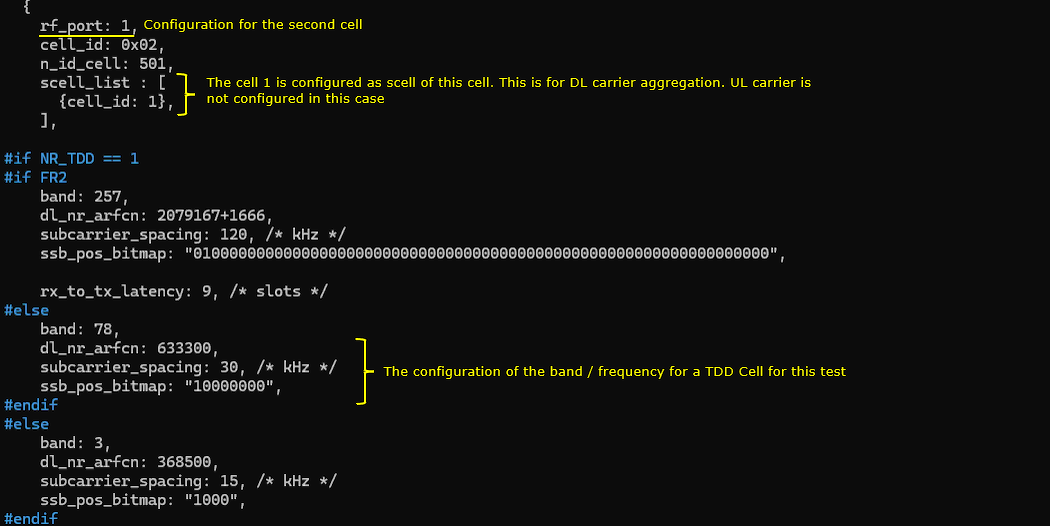
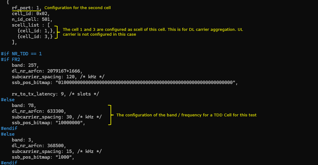
In this configuration, nr_cell_list defines the first NR cell on rf_port=1 with cell_id=0x01 and n_id_cell=501, and it also sets scell_list with {cell_id: 1} so cell 1 is configured as the SCell of this cell for downlink carrier aggregation, while uplink CA is not configured in this case. Since NR_TDD==1, the band and frequency for this TDD cell are configured with band=78, dl_nr_arfcn=633300, subcarrier_spacing=30 kHz, and ssb_pos_bitmap="10000000", which defines the operating frequency, numerology, and the enabled SSB position pattern for this test.
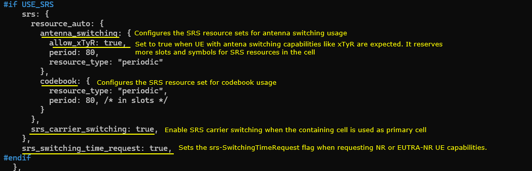
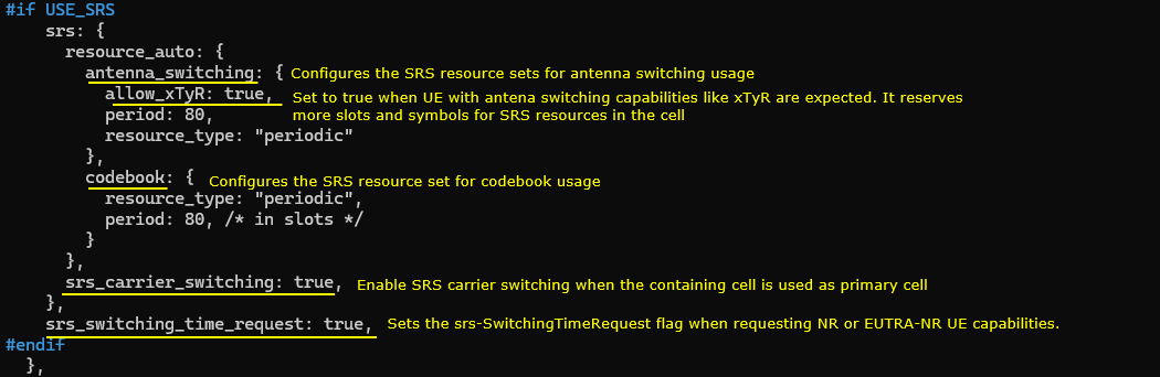
In this configuration, #if USE_SRS enables the srs block and uses resource_auto to create periodic SRS resources for two purposes, where antenna_switching is used to configure SRS resource sets for antenna switching operation and allow_xTyR:true tells the cell to expect UEs with antenna switching capability (like xTxR) so it reserves additional slots and symbols for SRS; it also defines a separate codebook resource set with resource_type:"periodic" and period:80 slots for codebook-based sounding, then sets srs_carrier_switching:true to enable SRS carrier switching when this cell is used as the primary cell, and finally sets srs_switching_time_request:true so the gNB/eNB can include the srs-SwitchingTimeRequest indication when requesting NR or EUTRA-NR UE capability information.
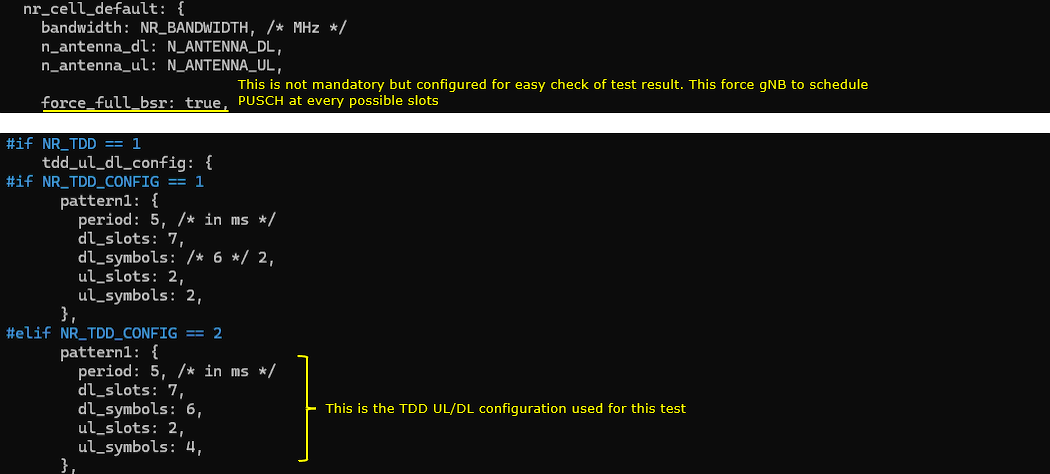
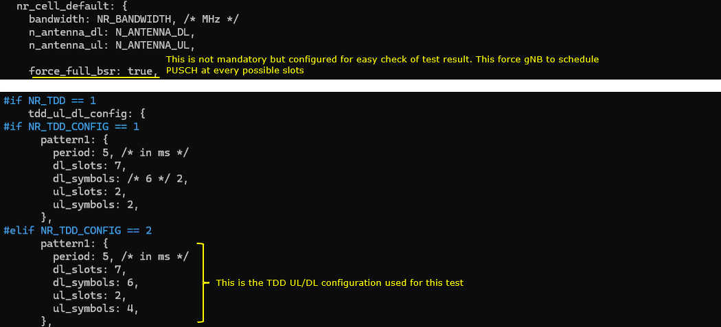
In this configuration, nr_cell_default defines common cell parameters with bandwidth: NR_BANDWIDTH and the RF port counts n_antenna_dl: N_ANTENNA_DL and n_antenna_ul: N_ANTENNA_UL, and it also sets force_full_bsr:true as a non-mandatory option to simplify test verification by forcing the gNB to see continuous buffer status so it schedules uplink (PUSCH) as often as possible. Since NR_TDD==1 and NR_TDD_CONFIG==2, the active tdd_ul_dl_config uses pattern1 with period:5 ms, dl_slots:7, dl_symbols:6, ul_slots:2, and ul_symbols:4, which defines the DL/UL slot and symbol distribution used for this TDD test.
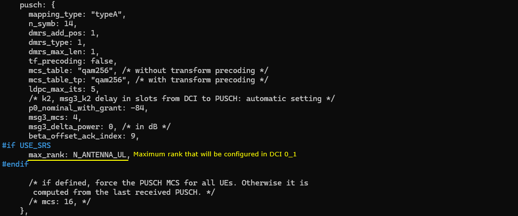
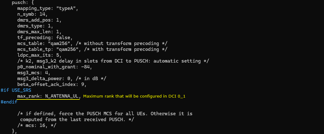
In this configuration, max_rank: N_ANTENNA_UL is the key point because it sets the maximum uplink rank that the gNB will configure and signal in DCI 0_1, so the UL MIMO rank limit directly follows the configured number of uplink antenna ports (this line is applied when USE_SRS is enabled)
Perform the Test
Testing process is simple. You only have to do NR SA attach (See NR SA Attach tutorial if you are not familiar with the process). The important part is to check the log and verify if you get the SRS as configured.
Log Analysis
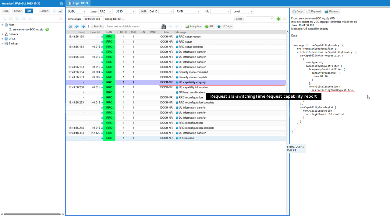
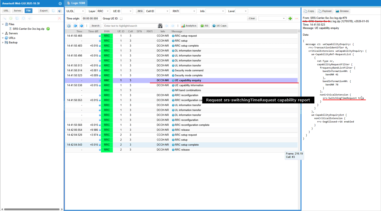
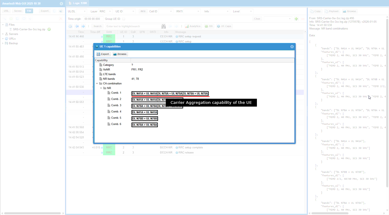
gNB sends UE Capability Enquiry with srs-SwitchingTimeRequest = true, so it explicitly asks the UE to include the SRS switching time capability information in the capability report
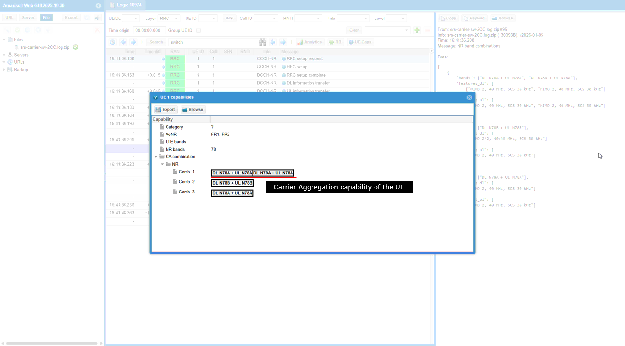
Then UE notifies on UE CA combination list shown in the �UE1 capabilities� window, where the UE reports that it supports NR band n78 and multiple downlink carrier aggregation combinations, including entries like DL n78A + UL n78A + DL n78A + UL n78A, which indicates multi-carrier operation capability for the same band and the corresponding uplink pairing.
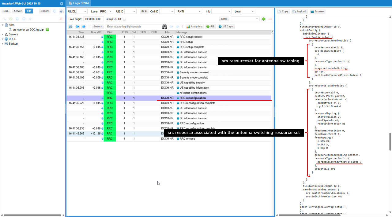
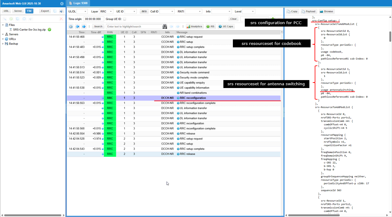
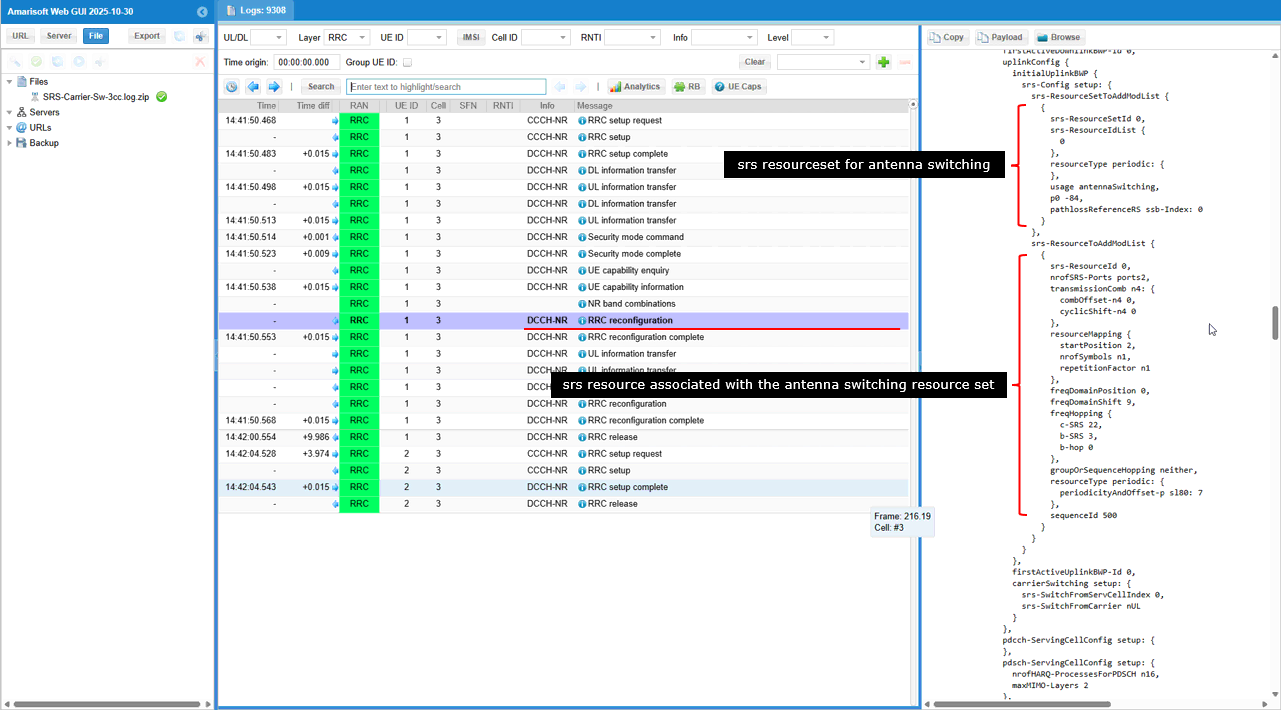
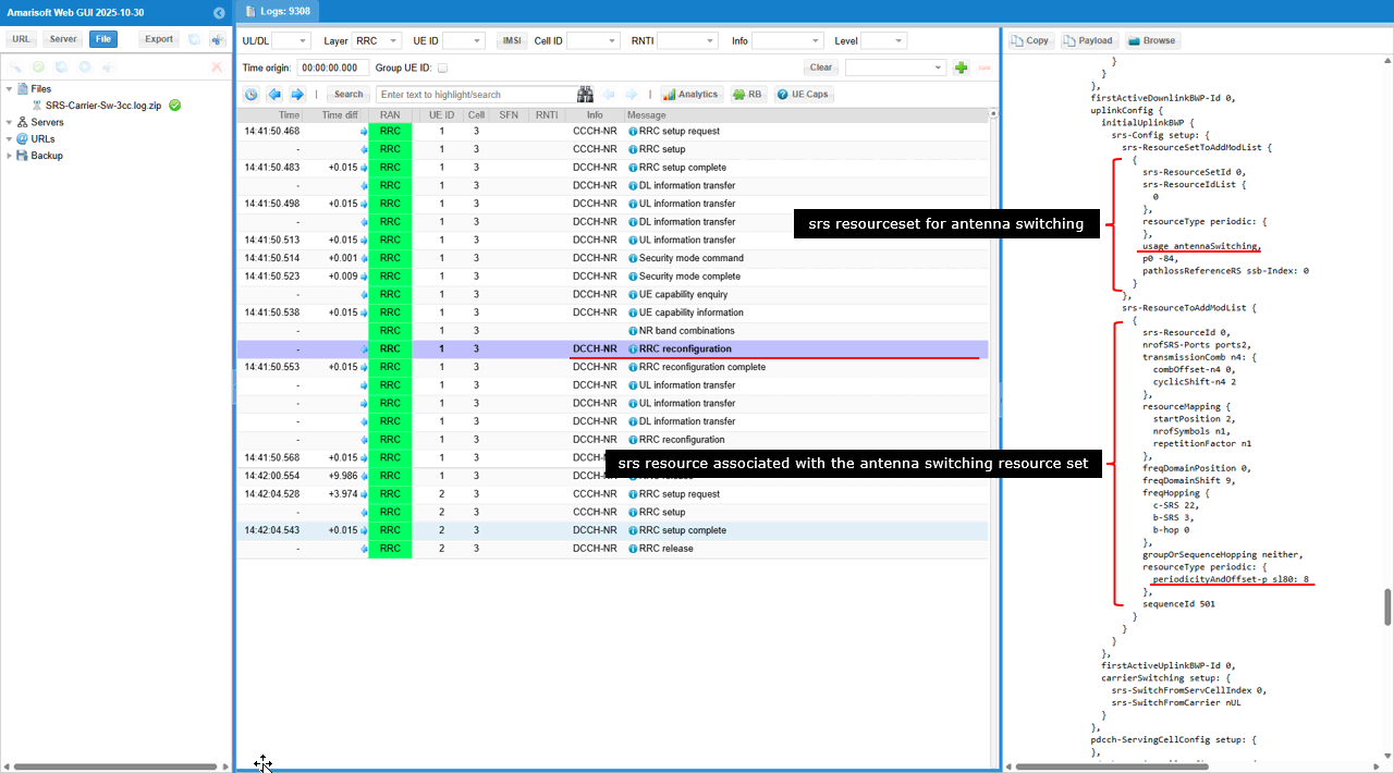
gNB sends RRC Reconfiguration that includes the SRS configuration for the PCC, and it explicitly provides two SRS resource sets, one with usage=codebook for codebook-based sounding and another with usage=antennaSwitching for antenna switching support, so the UE receives both the codebook SRS resourceset and the antenna-switching SRS resourceset in the same reconfiguration
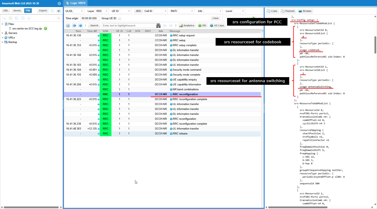
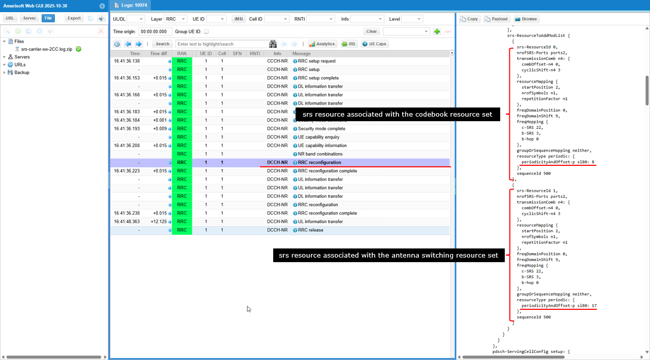
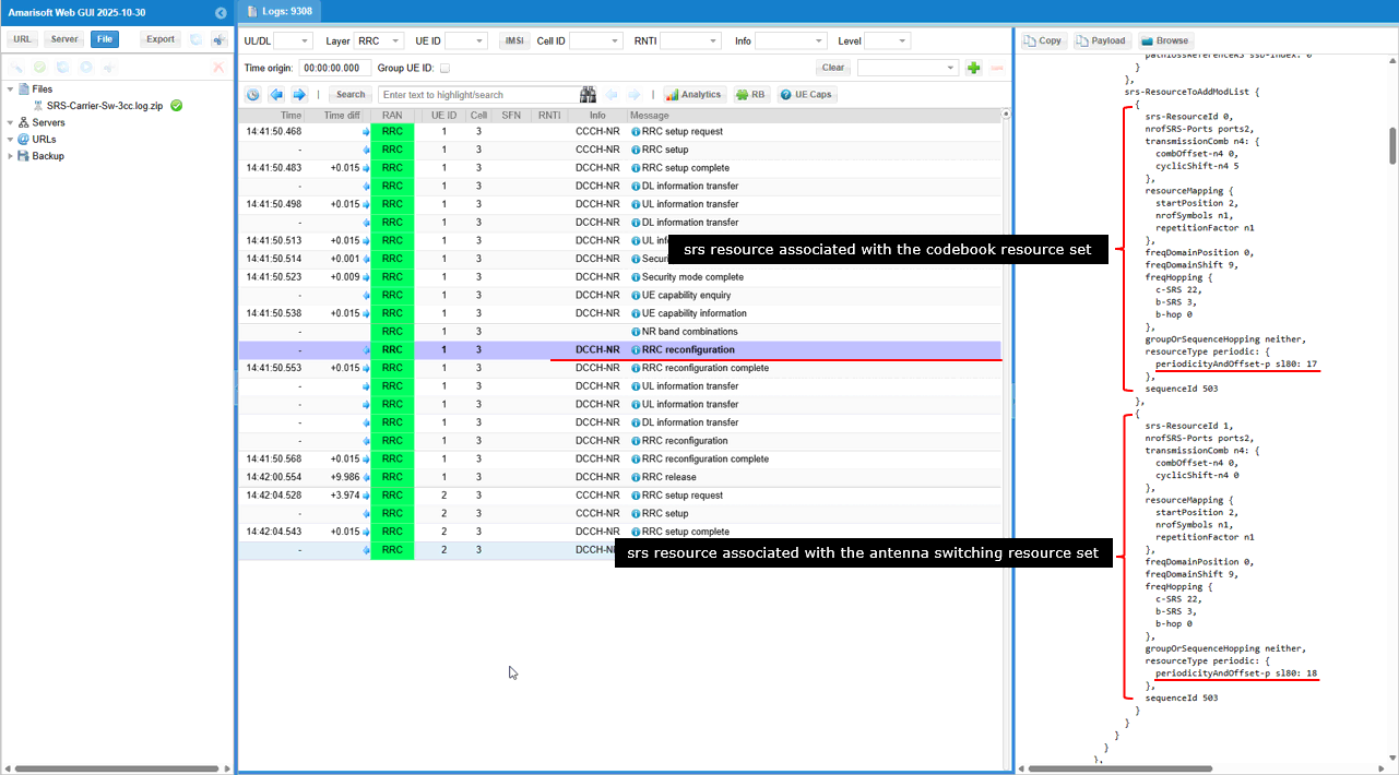
The same RRC Reconfiguration delivers the actual SRS resources in srs-ResourceToAddModList and maps them to the two resource sets, so one SRS resource is associated with the codebook resource set and another SRS resource is associated with the antennaSwitching resource set. Each SRS resource entry then defines the concrete transmission behavior such as nrofSRS-Ports (for example ports2), transmissionComb (comb offset and cyclic shift), resourceMapping (start position, number of symbols, repetition), frequency-domain allocation and hopping, and the periodic timing via resourceType periodic where periodicityAndOffset sets when the UE transmits SRS (for example sl80: 8 for the codebook resource and sl80: 17 for the antenna switching resource), and sequenceId defines the sounding sequence initialization.
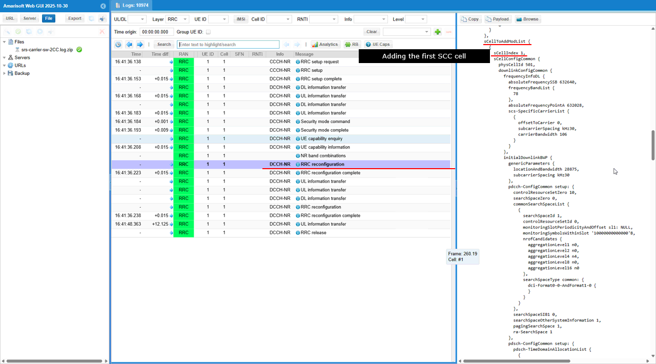
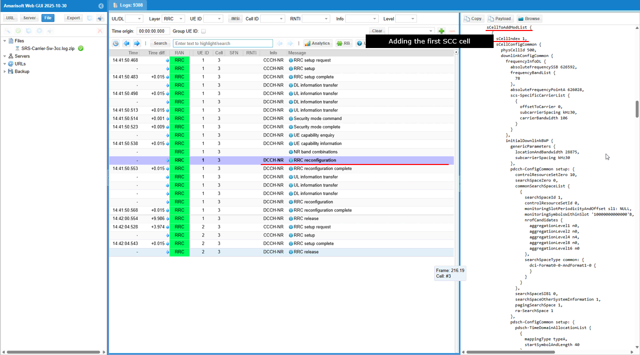
The same RRC Reconfiguration adds the first secondary component carrier (SCC) under sCellToAddModList, where sCellIndex: 1 is created and cellIdentificationCommon defines the SCC identity and RF settings such as physCellId: 501, frequencyBandList: 78, absoluteFrequencySSB and absoluteFrequencyPointA, and ssbSubcarrierSpacing: kHz30 with carrierBandwidth: 106.
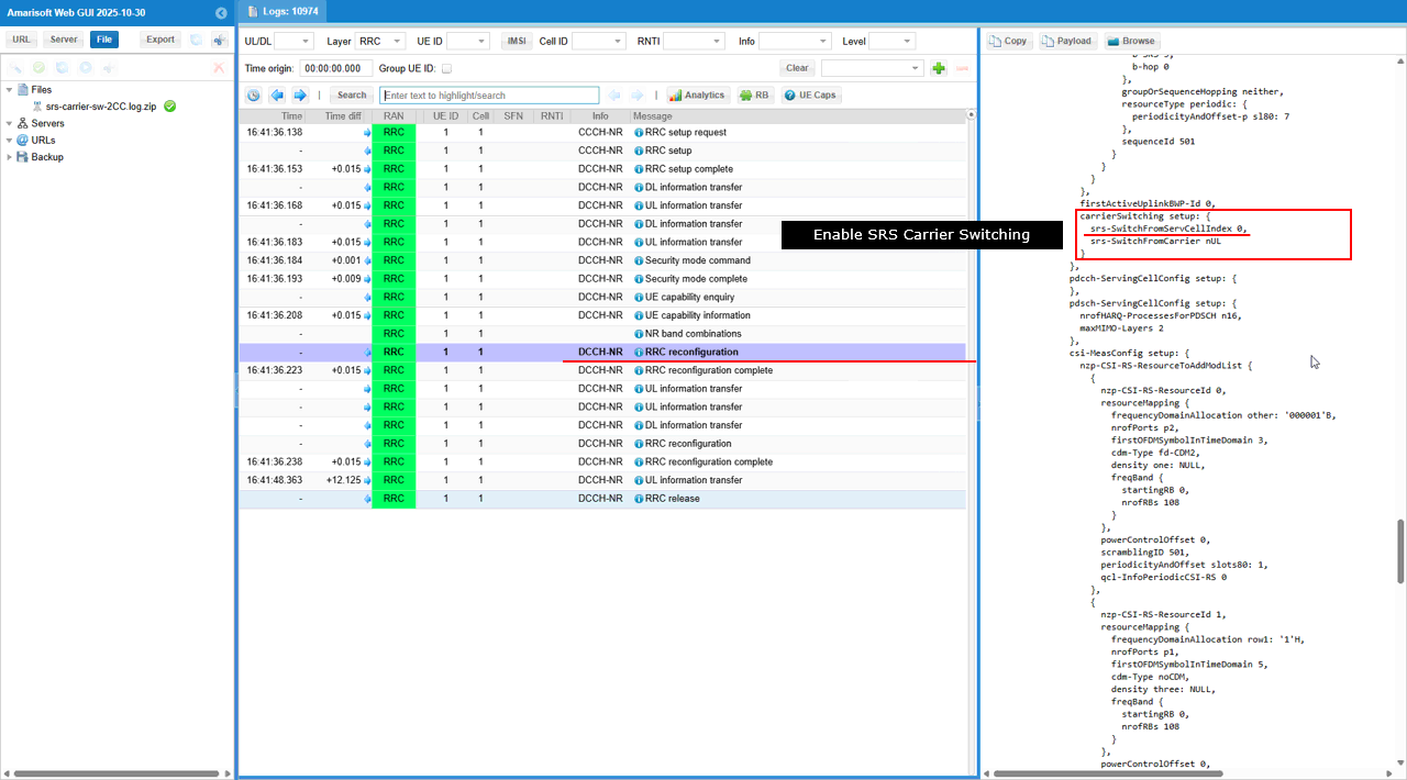
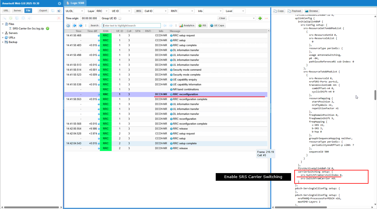
SCC enables SRS Carrier Switching by including carrierSwitching setup with srs-SwitchFromServingCellIndex: 0 and srs-SwitchFromCarrier: null, which tells the UE that SRS switching is configured and the switching reference is anchored to serving cell index 0.
The antenna switching SRS setup configured for SCC, where srs-ResourceSetToAddModList includes an SRS resource set with usage=antennaSwitching and it points to its resource list, so the UE knows this resource set is dedicated for antenna switching operation. The highlighted srs-ResourceToAddModList entry then provides the concrete SRS resource tied to that set, including nrofSRS-Ports: ports2, transmissionComb and resourceMapping parameters, and the periodic timing via resourceType periodic where periodicityAndOffset defines when the UE transmits this antenna-switching SRS (shown here as sl80: 7), with sequenceId defining the sounding sequence initialization.
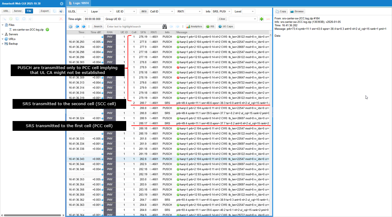
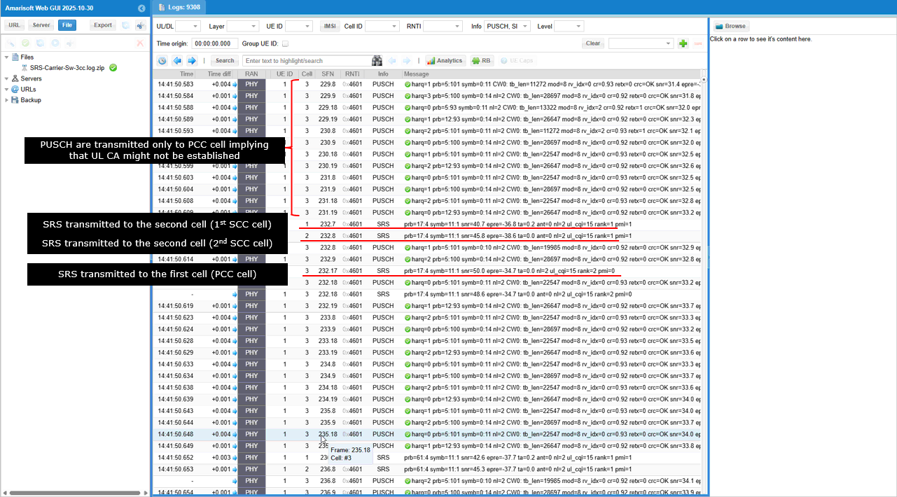
In this log, SRS is seen on both serving cells while PUSCH stays on the PCC, where the PHY layer prints show SRS transmitted on the second cell (SCC) and later SRS transmitted on the first cell (PCC), but the repeated uplink data transmissions are still logged as PUSCH on the PCC only, which suggests that UL CA is not established for user data and the second carrier is being used mainly for sounding
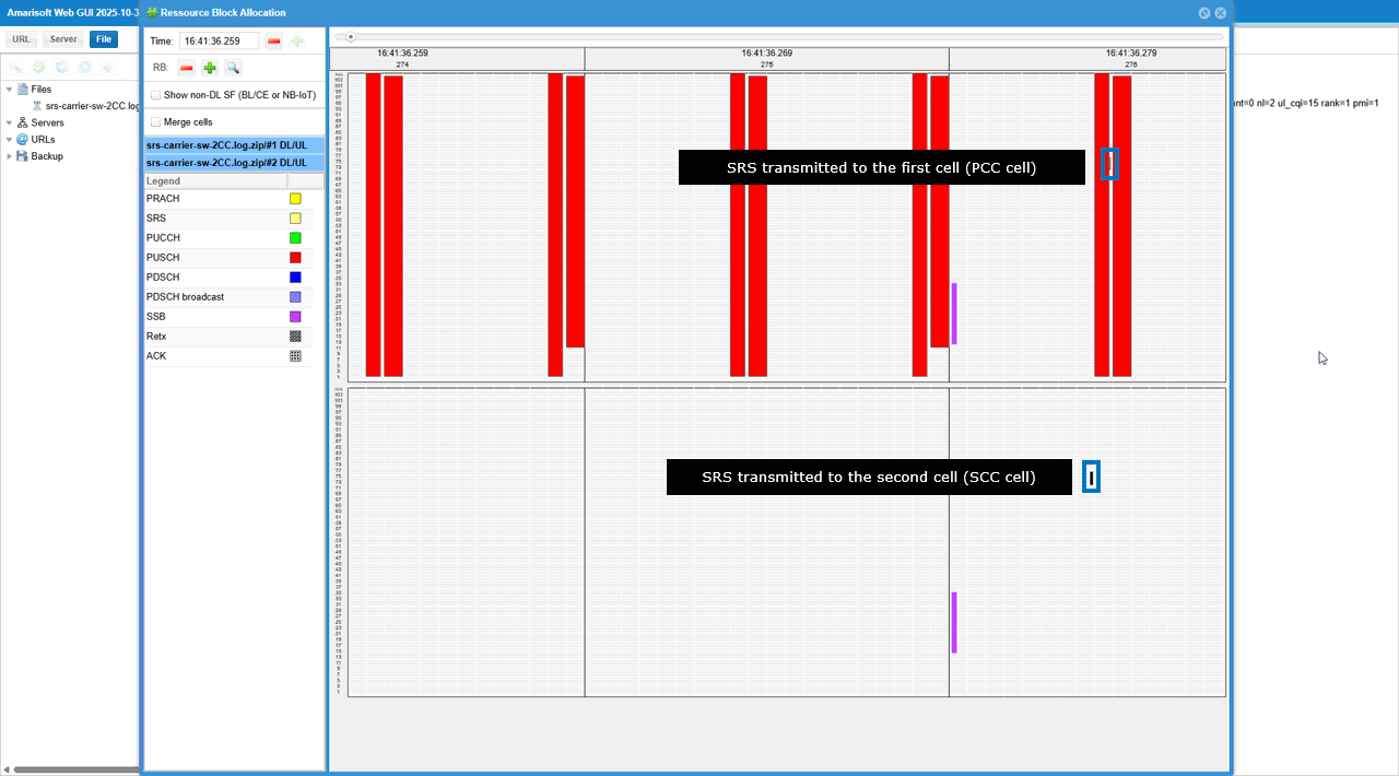
In this Resource Block Allocation view, the key point is that SRS appears on both carriers, where the top panel (cell #1 / PCC) shows an SRS occasion and the bottom panel (cell #2 / SCC) also shows an SRS occasion at a different time, which visually confirms that the UE is switching SRS transmission between PCC and SCC. The wide red blocks in the PCC pane indicate that uplink data scheduling (PUSCH) is still concentrated on the PCC, while the SCC pane is mostly empty except for the brief SRS transmission, so the second carrier is being exercised mainly for sounding rather than continuous uplink data.
Test 2 : SRS Carrier Switching with 3CC DL CA/no UL CA
The purpose of this test is to demonstrate how to configure and verify SRS carrier switching, by applying the RRC configuration that enables SRS switching and then confirming in the logs/RB allocation view that the UE transmits SRS on both PCC and two SCCs while uplink data (PUSCH) remains on the PCC
Configuration
I have used gnb-3cc-sa-srs-sw.cfg

I am using the default mme, ims config as shown below.
In gnb-3cc-sa-srs-sw.cfg , it is configured as follows.
In this configuration, NR_TDD=1 enables NR TDD (not FDD) and the active FR1 settings are NR_TDD_CONFIG=2 (FR1 TDD configuration index) and NR_BANDWIDTH=40 (cell bandwidth). it then defines the RF port configuration with N_ANTENNA_DL=2 for 2x2 MIMO downlink, and finally enables uplink sounding by setting SRS_SW=1 to activate srs_carrier_switching and USE_SRS=1 to enable periodic SRS transmission using the configured uplink antenna ports.

In this configuration, nr_cell_list defines the first NR cell on rf_port=0 with cell_id=0x01 and n_id_cell=500, and it also sets scell_list with {cell_id: 2, cell_id: 3} so cell 2 and 3 is configured as the SCell of this cell for downlink carrier aggregation, while uplink CA is not configured in this case. Since NR_TDD==1, the band and frequency for this TDD cell are configured with band=78, dl_nr_arfcn=627300, subcarrier_spacing=30 kHz, and ssb_pos_bitmap="10000000", which defines the operating frequency, numerology, and the enabled SSB position pattern for this test.
In this configuration, #if USE_SRS enables the srs block and uses resource_auto to create periodic SRS resources for two purposes, where antenna_switching is used to configure SRS resource sets for antenna switching operation and allow_xTyR:true tells the cell to expect UEs with antenna switching capability (like xTxR) so it reserves additional slots and symbols for SRS; it also defines a separate codebook resource set with resource_type:"periodic" and period:80 slots for codebook-based sounding, then sets srs_carrier_switching:true to enable SRS carrier switching when this cell is used as the primary cell, and finally sets srs_switching_time_request:true so the gNB/eNB can include the srs-SwitchingTimeRequest indication when requesting NR or EUTRA-NR UE capability information.
In this configuration, nr_cell_list defines the first NR cell on rf_port=1 with cell_id=0x01 and n_id_cell=501, and it also sets scell_list with {cell_id: 1,cell_id: 3} so cell 1 and 3 are configured as the SCell of this cell for downlink carrier aggregation, while uplink CA is not configured in this case. Since NR_TDD==1, the band and frequency for this TDD cell are configured with band=78, dl_nr_arfcn=633300, subcarrier_spacing=30 kHz, and ssb_pos_bitmap="10000000", which defines the operating frequency, numerology, and the enabled SSB position pattern for this test.
In this configuration, #if USE_SRS enables the srs block and uses resource_auto to create periodic SRS resources for two purposes, where antenna_switching is used to configure SRS resource sets for antenna switching operation and allow_xTyR:true tells the cell to expect UEs with antenna switching capability (like xTxR) so it reserves additional slots and symbols for SRS; it also defines a separate codebook resource set with resource_type:"periodic" and period:80 slots for codebook-based sounding, then sets srs_carrier_switching:true to enable SRS carrier switching when this cell is used as the primary cell, and finally sets srs_switching_time_request:true so the gNB/eNB can include the srs-SwitchingTimeRequest indication when requesting NR or EUTRA-NR UE capability information.
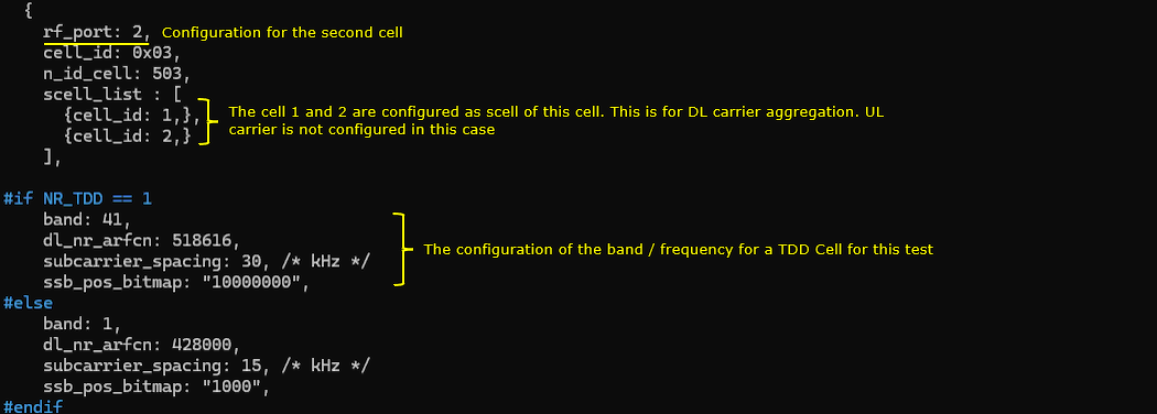
In this configuration, nr_cell_list defines the first NR cell on rf_port=2 with cell_id=0x03 and n_id_cell=503, and it also sets scell_list with {cell_id: 1,cell_id: 2} so cell 1 and 2 are configured as the SCell of this cell for downlink carrier aggregation, while uplink CA is not configured in this case. Since NR_TDD==1, the band and frequency for this TDD cell are configured with band=41, dl_nr_arfcn=518616, subcarrier_spacing=30 kHz, and ssb_pos_bitmap="10000000", which defines the operating frequency, numerology, and the enabled SSB position pattern for this test.
In this configuration, #if USE_SRS enables the srs block and uses resource_auto to create periodic SRS resources for two purposes, where antenna_switching is used to configure SRS resource sets for antenna switching operation and allow_xTyR:true tells the cell to expect UEs with antenna switching capability (like xTxR) so it reserves additional slots and symbols for SRS; it also defines a separate codebook resource set with resource_type:"periodic" and period:80 slots for codebook-based sounding, then sets srs_carrier_switching:true to enable SRS carrier switching when this cell is used as the primary cell, and finally sets srs_switching_time_request:true so the gNB/eNB can include the srs-SwitchingTimeRequest indication when requesting NR or EUTRA-NR UE capability information.
In this configuration, nr_cell_default defines common cell parameters with bandwidth: NR_BANDWIDTH and the RF port counts n_antenna_dl: N_ANTENNA_DL and n_antenna_ul: N_ANTENNA_UL, and it also sets force_full_bsr:true as a non-mandatory option to simplify test verification by forcing the gNB to see continuous buffer status so it schedules uplink (PUSCH) as often as possible. Since NR_TDD==1 and NR_TDD_CONFIG==2, the active tdd_ul_dl_config uses pattern1 with period:5 ms, dl_slots:7, dl_symbols:6, ul_slots:2, and ul_symbols:4, which defines the DL/UL slot and symbol distribution used for this TDD test.
In this configuration, max_rank: N_ANTENNA_UL is the key point because it sets the maximum uplink rank that the gNB will configure and signal in DCI 0_1, so the UL MIMO rank limit directly follows the configured number of uplink antenna ports (this line is applied when USE_SRS is enabled)
Perform the Test
Testing process is simple. You only have to do NR SA attach (See NR SA Attach tutorial if you are not familiar with the process). The important part is to check the log and verify if you get the SRS as configured.
Log Analysis
gNB sends UE Capability Enquiry with srs-SwitchingTimeRequest = true, so it explicitly asks the UE to include the SRS switching time capability information in the capability report
Then UE notifies on UE CA combination list shown in the �UE1 capabilities� window, where the UE reports that it supports NR band n78 and multiple downlink carrier aggregation combinations, including entries like DL n78A + UL n78A + DL n78A + UL n78A, which indicates multi-carrier operation capability for the same band and the corresponding uplink pairing.
gNB sends RRC Reconfiguration that includes the SRS configuration for the PCC, and it explicitly provides two SRS resource sets, one with usage=codebook for codebook-based sounding and another with usage=antennaSwitching for antenna switching support, so the UE receives both the codebook SRS resourceset and the antenna-switching SRS resourceset in the same reconfiguration
The same RRC Reconfiguration delivers the actual SRS resources in srs-ResourceToAddModList and maps them to the two resource sets, so one SRS resource is associated with the codebook resource set and another SRS resource is associated with the antennaSwitching resource set. Each SRS resource entry then defines the concrete transmission behavior such as nrofSRS-Ports (for example ports2), transmissionComb (comb offset and cyclic shift), resourceMapping (start position, number of symbols, repetition), frequency-domain allocation and hopping, and the periodic timing via resourceType periodic where periodicityAndOffset sets when the UE transmits SRS (for example sl80: 8 for the codebook resource and sl80: 17 for the antenna switching resource), and sequenceId defines the sounding sequence initialization.
The same RRC Reconfiguration adds the first secondary component carrier (SCC) under sCellToAddModList, where sCellIndex: 1 is created and cellIdentificationCommon defines the SCC identity and RF settings such as physCellId: 500, frequencyBandList: 78, absoluteFrequencySSB and absoluteFrequencyPointA, and ssbSubcarrierSpacing: kHz30 with carrierBandwidth: 106.
SCC enables SRS Carrier Switching by including carrierSwitching setup with srs-SwitchFromServingCellIndex: 0 and srs-SwitchFromCarrier: null, which tells the UE that SRS switching is configured and the switching reference is anchored to serving cell index 0.
The antenna switching SRS setup configured for SCC, where srs-ResourceSetToAddModList includes an SRS resource set with usage=antennaSwitching and it points to its resource list, so the UE knows this resource set is dedicated for antenna switching operation. The highlighted srs-ResourceToAddModList entry then provides the concrete SRS resource tied to that set, including nrofSRS-Ports: ports2, transmissionComb and resourceMapping parameters, and the periodic timing via resourceType periodic where periodicityAndOffset defines when the UE transmits this antenna-switching SRS (shown here as sl80: 7), with sequenceId defining the sounding sequence initialization.
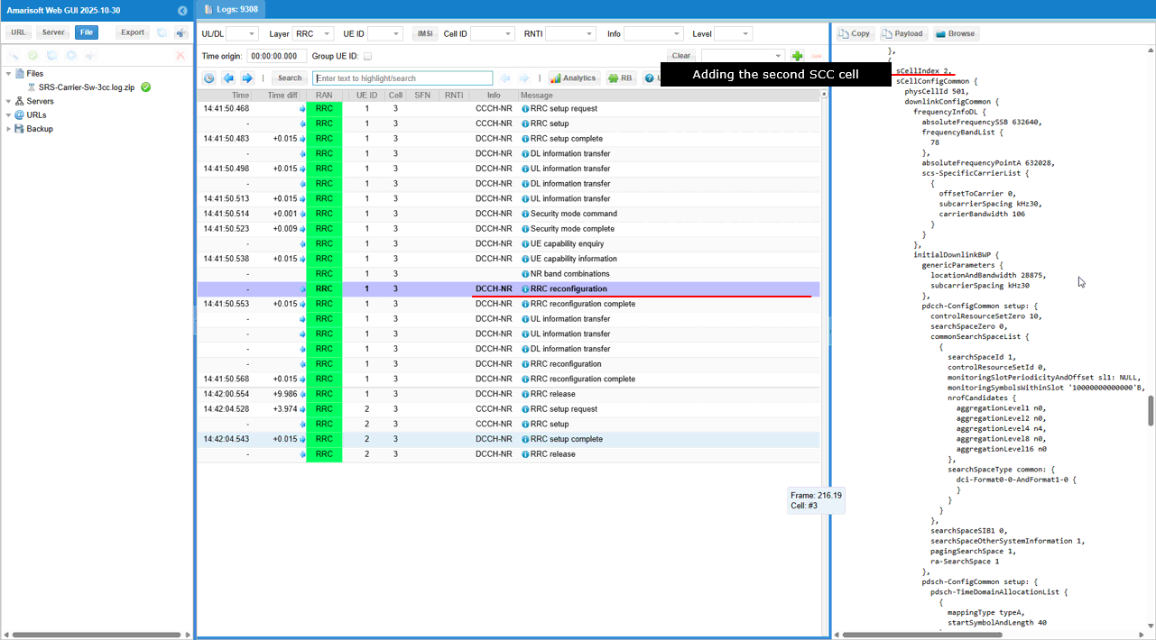
The same RRC Reconfiguration adds the second secondary component carrier (SCC) under sCellToAddModList, where sCellIndex: 2 is created and cellIdentificationCommon defines the SCC identity and RF settings such as physCellId: 501, frequencyBandList: 78, absoluteFrequencySSB and absoluteFrequencyPointA, and ssbSubcarrierSpacing: kHz30 with carrierBandwidth: 106.
The SCC enables SRS Carrier Switching by including carrierSwitching setup with srs-SwitchFromServingCellIndex: 0 and srs-SwitchFromCarrier: null, which tells the UE that SRS switching is configured and the switching reference is anchored to serving cell index 0.
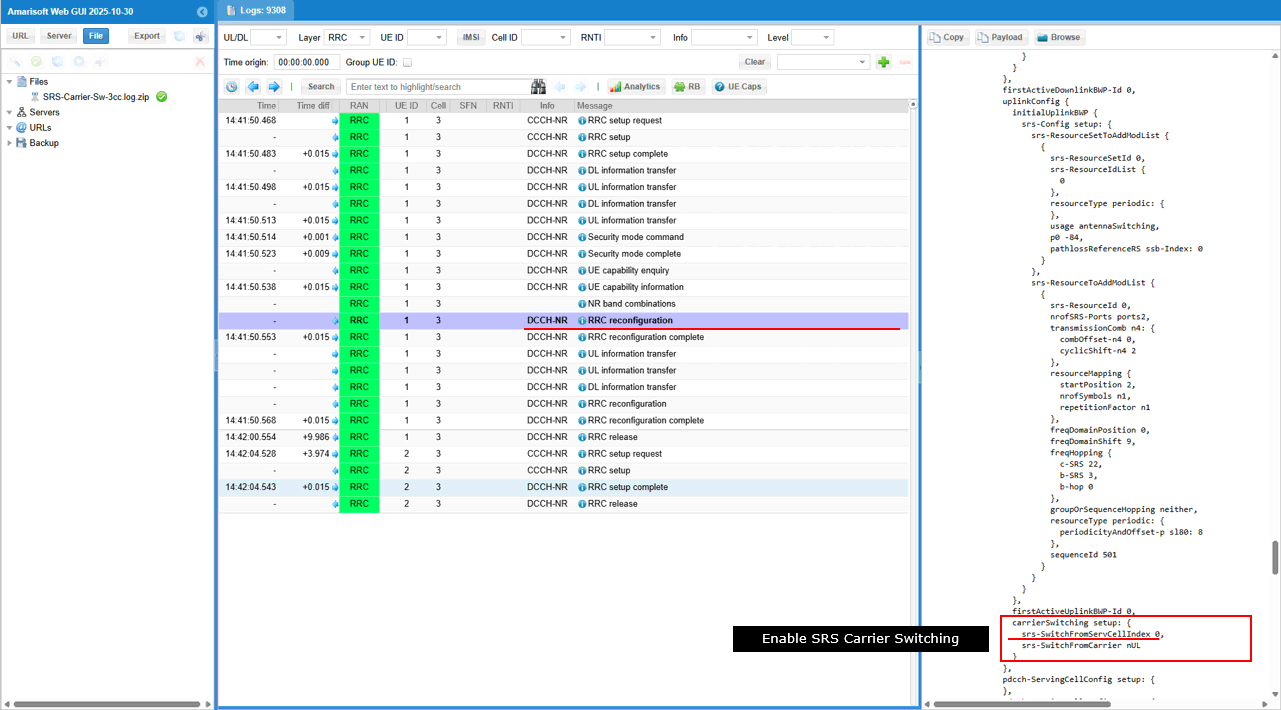
The antenna switching SRS setup configured for SCC, where srs-ResourceSetToAddModList includes an SRS resource set with usage=antennaSwitching and it points to its resource list, so the UE knows this resource set is dedicated for antenna switching operation. The highlighted srs-ResourceToAddModList entry then provides the concrete SRS resource tied to that set, including nrofSRS-Ports: ports2, transmissionComb and resourceMapping parameters, and the periodic timing via resourceType periodic where periodicityAndOffset defines when the UE transmits this antenna-switching SRS (shown here as sl80: 7), with sequenceId defining the sounding sequence initialization.
In this log, SRS is seen on both serving cells while PUSCH stays on the PCC, where the PHY layer prints show SRS transmitted on the second cells(1st and 2nd SCC) and later SRS transmitted on the first cell (PCC), but the repeated uplink data transmissions are still logged as PUSCH on the PCC only, which suggests that UL CA is not established for user data and the second carrier is being used mainly for sounding
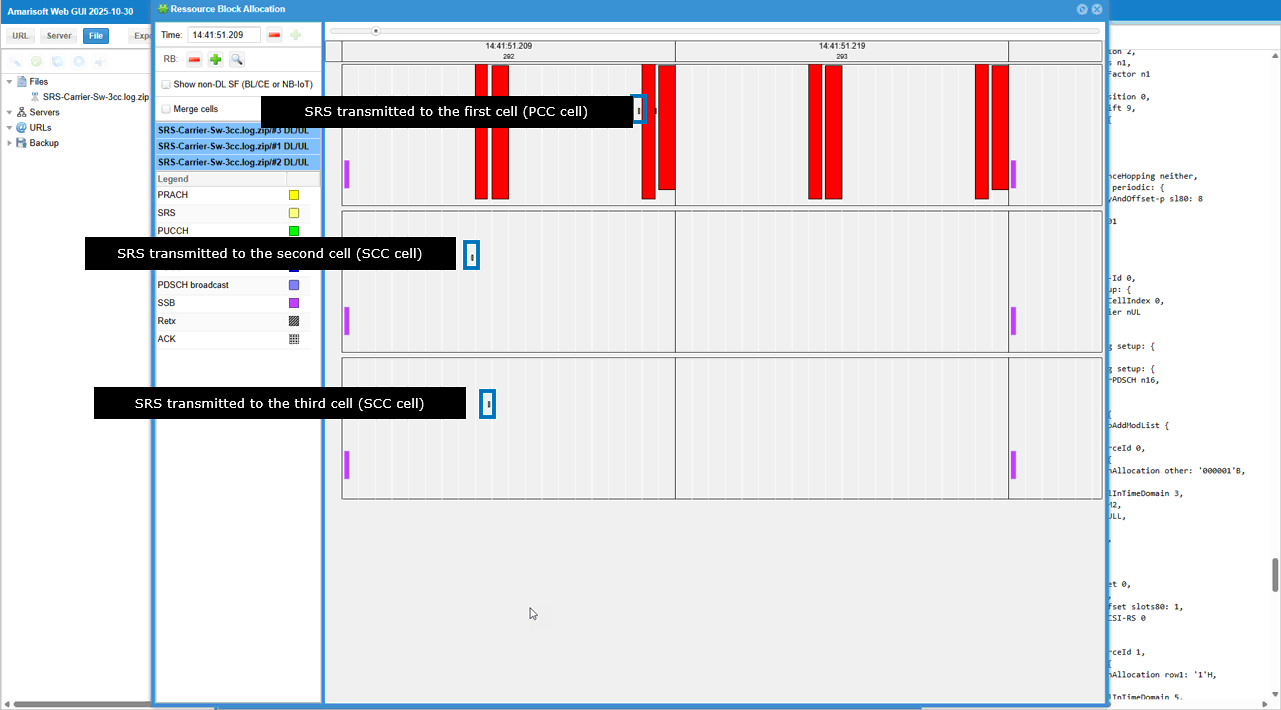
In this Resource Block Allocation view, the key point is that SRS appears on both carriers, where the top panel (cell #3 / PCC) shows an SRS occasion and the two lower panel (cell #1 and #2 / SCC) also shows an SRS occasion at a different time, which visually confirms that the UE is switching SRS transmission between PCC and SCC. The wide red blocks in the PCC pane indicate that uplink data scheduling (PUSCH) is still concentrated on the PCC, while the SCC pane is mostly empty except for the brief SRS transmission, so the second carrier is being exercised mainly for sounding rather than continuous uplink data.
RRC / NAS Signaling
RrcReconfiguration (SA)
: This is the RrcSetup message sent by gNB to configure NR SA. (
{
message c1: rrcReconfiguration: {
rrc-TransactionIdentifier 0,
criticalExtensions rrcReconfiguration: {
nonCriticalExtension {
masterCellGroup {
cellGroupId 0,
mac-CellGroupConfig {
phr-Config setup: {
phr-PeriodicTimer sf500,
phr-ProhibitTimer sf200,
phr-Tx-PowerFactorChange dB3,
multiplePHR TRUE,
dummy FALSE,
phr-Type2OtherCell FALSE,
phr-ModeOtherCG real
},
skipUplinkTxDynamic FALSE
},
spCellConfig {
spCellConfigDedicated {
initialDownlinkBWP {
pdsch-Config setup: {
resourceAllocation resourceAllocationType1,
rbg-Size config1,
mcs-Table qam256,
prb-BundlingType staticBundling: {
bundleSize wideband
}
}
},
uplinkConfig {
initialUplinkBWP {
pucch-Config setup: {
resourceToAddModList {
{
pucch-ResourceId 10,
startingPRB 0,
format format2: {
nrofPRBs 2,
nrofSymbols 1,
startingSymbolIndex 8
}
},
{
pucch-ResourceId 11,
startingPRB 0,
format format2: {
nrofPRBs 2,
nrofSymbols 1,
startingSymbolIndex 8
}
}
}
},
pusch-Config setup: {
txConfig codebook,
resourceAllocation resourceAllocationType1,
mcs-Table qam256,
mcs-TableTransformPrecoder qam256,
codebookSubset nonCoherent,
maxRank 2
},
srs-Config setup: {
srs-ResourceSetToAddModList {
{
srs-ResourceSetId 0,
srs-ResourceIdList {
0
},
resourceType periodic: {
},
usage codebook,
p0 -84,
pathlossReferenceRS ssb-Index: 0
},
{
srs-ResourceSetId 1,
srs-ResourceIdList {
1
},
resourceType periodic: {
},
usage antennaSwitching,
p0 -84,
pathlossReferenceRS ssb-Index: 0
}
},
srs-ResourceToAddModList {
{
srs-ResourceId 0,
nrofSRS-Ports ports2,
transmissionComb n4: {
combOffset-n4 0,
cyclicShift-n4 5
},
resourceMapping {
startPosition 2,
nrofSymbols n1,
repetitionFactor n1
},
freqDomainPosition 0,
freqDomainShift 9,
freqHopping {
c-SRS 22,
b-SRS 3,
b-hop 0
},
groupOrSequenceHopping neither,
resourceType periodic: {
periodicityAndOffset-p sl80: 17
},
sequenceId 503
},
{
srs-ResourceId 1,
nrofSRS-Ports ports2,
transmissionComb n4: {
combOffset-n4 0,
cyclicShift-n4 0
},
resourceMapping {
startPosition 2,
nrofSymbols n1,
repetitionFactor n1
},
freqDomainPosition 0,
freqDomainShift 9,
freqHopping {
c-SRS 22,
b-SRS 3,
b-hop 0
},
groupOrSequenceHopping neither,
resourceType periodic: {
periodicityAndOffset-p sl80: 18
},
sequenceId 503
}
}
}
}
},
pdsch-ServingCellConfig setup: {
nrofHARQ-ProcessesForPDSCH n16,
maxMIMO-Layers 2
},
csi-MeasConfig setup: {
csi-ReportConfigToAddModList {
{
reportConfigId 1,
carrier 1,
resourcesForChannelMeasurement 0,
csi-IM-ResourcesForInterference 1,
reportConfigType periodic: {
reportSlotConfig slots80: 18,
pucch-CSI-ResourceList {
{
uplinkBandwidthPartId 0,
pucch-Resource 10
}
}
},
reportQuantity cri-RI-PMI-CQI: NULL,
reportFreqConfiguration {
cqi-FormatIndicator widebandCQI,
pmi-FormatIndicator widebandPMI
},
timeRestrictionForChannelMeasurements notConfigured,
timeRestrictionForInterferenceMeasurements notConfigured,
codebookConfig {
codebookType type1: {
subType typeI-SinglePanel: {
nrOfAntennaPorts two: {
twoTX-CodebookSubsetRestriction '111111'B
},
typeI-SinglePanel-ri-Restriction '03'H
},
codebookMode 1
}
},
groupBasedBeamReporting disabled: {
},
cqi-Table table2,
subbandSize value1
},
{
reportConfigId 2,
carrier 2,
resourcesForChannelMeasurement 0,
csi-IM-ResourcesForInterference 1,
reportConfigType periodic: {
reportSlotConfig slots80: 19,
pucch-CSI-ResourceList {
{
uplinkBandwidthPartId 0,
pucch-Resource 11
}
}
},
reportQuantity cri-RI-PMI-CQI: NULL,
reportFreqConfiguration {
cqi-FormatIndicator widebandCQI,
pmi-FormatIndicator widebandPMI
},
timeRestrictionForChannelMeasurements notConfigured,
timeRestrictionForInterferenceMeasurements notConfigured,
codebookConfig {
codebookType type1: {
subType typeI-SinglePanel: {
nrOfAntennaPorts two: {
twoTX-CodebookSubsetRestriction '111111'B
},
typeI-SinglePanel-ri-Restriction '03'H
},
codebookMode 1
}
},
groupBasedBeamReporting disabled: {
},
cqi-Table table2,
subbandSize value1
}
}
},
tag-Id 0
}
},
sCellToAddModList {
{
sCellIndex 1,
sCellConfigCommon {
physCellId 500,
downlinkConfigCommon {
frequencyInfoDL {
absoluteFrequencySSB 626592,
frequencyBandList {
78
},
absoluteFrequencyPointA 626028,
scs-SpecificCarrierList {
{
offsetToCarrier 0,
subcarrierSpacing kHz30,
carrierBandwidth 106
}
}
},
initialDownlinkBWP {
genericParameters {
locationAndBandwidth 28875,
subcarrierSpacing kHz30
},
pdcch-ConfigCommon setup: {
controlResourceSetZero 10,
searchSpaceZero 0,
commonSearchSpaceList {
{
searchSpaceId 1,
controlResourceSetId 0,
monitoringSlotPeriodicityAndOffset sl1: NULL,
monitoringSymbolsWithinSlot '10000000000000'B,
nrofCandidates {
aggregationLevel1 n0,
aggregationLevel2 n0,
aggregationLevel4 n4,
aggregationLevel8 n0,
aggregationLevel16 n0
},
searchSpaceType common: {
dci-Format0-0-AndFormat1-0 {
}
}
}
},
searchSpaceSIB1 0,
searchSpaceOtherSystemInformation 1,
pagingSearchSpace 1,
ra-SearchSpace 1
},
pdsch-ConfigCommon setup: {
pdsch-TimeDomainAllocationList {
{
mappingType typeA,
startSymbolAndLength 40
},
{
mappingType typeA,
startSymbolAndLength 57
}
}
}
}
},
uplinkConfigCommon {
frequencyInfoUL {
scs-SpecificCarrierList {
{
offsetToCarrier 0,
subcarrierSpacing kHz30,
carrierBandwidth 106
}
}
},
initialUplinkBWP {
genericParameters {
locationAndBandwidth 28875,
subcarrierSpacing kHz30
}
},
dummy ms500
},
ssb-PositionsInBurst mediumBitmap: '80'H,
ssb-periodicityServingCell ms20,
dmrs-TypeA-Position pos2,
ssbSubcarrierSpacing kHz30,
tdd-UL-DL-ConfigurationCommon {
referenceSubcarrierSpacing kHz30,
pattern1 {
dl-UL-TransmissionPeriodicity ms5,
nrofDownlinkSlots 7,
nrofDownlinkSymbols 6,
nrofUplinkSlots 2,
nrofUplinkSymbols 4
}
},
ss-PBCH-BlockPower -38
},
sCellConfigDedicated {
initialDownlinkBWP {
pdcch-Config setup: {
controlResourceSetToAddModList {
{
controlResourceSetId 2,
frequencyDomainResources '111111111111111110000000000000000000000000000'B,
duration 1,
cce-REG-MappingType nonInterleaved: NULL,
precoderGranularity sameAsREG-bundle
}
},
searchSpacesToAddModList {
{
searchSpaceId 2,
controlResourceSetId 2,
monitoringSlotPeriodicityAndOffset sl1: NULL,
monitoringSymbolsWithinSlot '10000000000000'B,
nrofCandidates {
aggregationLevel1 n0,
aggregationLevel2 n4,
aggregationLevel4 n0,
aggregationLevel8 n0,
aggregationLevel16 n0
},
searchSpaceType ue-Specific: {
dci-Formats formats0-1-And-1-1
}
}
}
},
pdsch-Config setup: {
dmrs-DownlinkForPDSCH-MappingTypeA setup: {
dmrs-AdditionalPosition pos1
},
tci-StatesToAddModList {
{
tci-StateId 0,
qcl-Type1 {
referenceSignal ssb: 0,
qcl-Type typeD
}
}
},
resourceAllocation resourceAllocationType1,
rbg-Size config1,
mcs-Table qam256,
prb-BundlingType staticBundling: {
bundleSize wideband
},
zp-CSI-RS-ResourceToAddModList {
{
zp-CSI-RS-ResourceId 0,
resourceMapping {
frequencyDomainAllocation row4: '100'B,
nrofPorts p4,
firstOFDMSymbolInTimeDomain 4,
cdm-Type fd-CDM2,
density one: NULL,
freqBand {
startingRB 0,
nrofRBs 108
}
},
periodicityAndOffset slots80: 1
}
},
p-ZP-CSI-RS-ResourceSet setup: {
zp-CSI-RS-ResourceSetId 0,
zp-CSI-RS-ResourceIdList {
0
}
}
}
},
firstActiveDownlinkBWP-Id 0,
uplinkConfig {
initialUplinkBWP {
srs-Config setup: {
srs-ResourceSetToAddModList {
{
srs-ResourceSetId 0,
srs-ResourceIdList {
0
},
resourceType periodic: {
},
usage antennaSwitching,
p0 -84,
pathlossReferenceRS ssb-Index: 0
}
},
srs-ResourceToAddModList {
{
srs-ResourceId 0,
nrofSRS-Ports ports2,
transmissionComb n4: {
combOffset-n4 0,
cyclicShift-n4 0
},
resourceMapping {
startPosition 2,
nrofSymbols n1,
repetitionFactor n1
},
freqDomainPosition 0,
freqDomainShift 9,
freqHopping {
c-SRS 22,
b-SRS 3,
b-hop 0
},
groupOrSequenceHopping neither,
resourceType periodic: {
periodicityAndOffset-p sl80: 7
},
sequenceId 500
}
}
}
},
firstActiveUplinkBWP-Id 0,
carrierSwitching setup: {
srs-SwitchFromServCellIndex 0,
srs-SwitchFromCarrier nUL
}
},
pdcch-ServingCellConfig setup: {
},
pdsch-ServingCellConfig setup: {
nrofHARQ-ProcessesForPDSCH n16,
maxMIMO-Layers 2
},
csi-MeasConfig setup: {
nzp-CSI-RS-ResourceToAddModList {
{
nzp-CSI-RS-ResourceId 0,
resourceMapping {
frequencyDomainAllocation other: '010000'B,
nrofPorts p2,
firstOFDMSymbolInTimeDomain 3,
cdm-Type fd-CDM2,
density one: NULL,
freqBand {
startingRB 0,
nrofRBs 108
}
},
powerControlOffset 0,
scramblingID 500,
periodicityAndOffset slots80: 1,
qcl-InfoPeriodicCSI-RS 0
},
{
nzp-CSI-RS-ResourceId 1,
resourceMapping {
frequencyDomainAllocation row1: '4'H,
nrofPorts p1,
firstOFDMSymbolInTimeDomain 5,
cdm-Type noCDM,
density three: NULL,
freqBand {
startingRB 0,
nrofRBs 108
}
},
powerControlOffset 0,
scramblingID 500,
periodicityAndOffset slots80: 1,
qcl-InfoPeriodicCSI-RS 0
},
{
nzp-CSI-RS-ResourceId 2,
resourceMapping {
frequencyDomainAllocation row1: '4'H,
nrofPorts p1,
firstOFDMSymbolInTimeDomain 9,
cdm-Type noCDM,
density three: NULL,
freqBand {
startingRB 0,
nrofRBs 108
}
},
powerControlOffset 0,
scramblingID 500,
periodicityAndOffset slots80: 1,
qcl-InfoPeriodicCSI-RS 0
},
{
nzp-CSI-RS-ResourceId 3,
resourceMapping {
frequencyDomainAllocation row1: '4'H,
nrofPorts p1,
firstOFDMSymbolInTimeDomain 5,
cdm-Type noCDM,
density three: NULL,
freqBand {
startingRB 0,
nrofRBs 108
}
},
powerControlOffset 0,
scramblingID 500,
periodicityAndOffset slots80: 2,
qcl-InfoPeriodicCSI-RS 0
},
{
nzp-CSI-RS-ResourceId 4,
resourceMapping {
frequencyDomainAllocation row1: '4'H,
nrofPorts p1,
firstOFDMSymbolInTimeDomain 9,
cdm-Type noCDM,
density three: NULL,
freqBand {
startingRB 0,
nrofRBs 108
}
},
powerControlOffset 0,
scramblingID 500,
periodicityAndOffset slots80: 2,
qcl-InfoPeriodicCSI-RS 0
}
},
nzp-CSI-RS-ResourceSetToAddModList {
{
nzp-CSI-ResourceSetId 0,
nzp-CSI-RS-Resources {
0
}
},
{
nzp-CSI-ResourceSetId 1,
nzp-CSI-RS-Resources {
1,
2,
3,
4
},
trs-Info true
}
},
csi-IM-ResourceToAddModList {
{
csi-IM-ResourceId 0,
csi-IM-ResourceElementPattern pattern1: {
subcarrierLocation-p1 s8,
symbolLocation-p1 4
},
freqBand {
startingRB 0,
nrofRBs 108
},
periodicityAndOffset slots80: 1
}
},
csi-IM-ResourceSetToAddModList {
{
csi-IM-ResourceSetId 0,
csi-IM-Resources {
0
}
}
},
csi-ResourceConfigToAddModList {
{
csi-ResourceConfigId 0,
csi-RS-ResourceSetList nzp-CSI-RS-SSB: {
nzp-CSI-RS-ResourceSetList {
0
}
},
bwp-Id 0,
resourceType periodic
},
{
csi-ResourceConfigId 1,
csi-RS-ResourceSetList csi-IM-ResourceSetList: {
0
},
bwp-Id 0,
resourceType periodic
},
{
csi-ResourceConfigId 2,
csi-RS-ResourceSetList nzp-CSI-RS-SSB: {
nzp-CSI-RS-ResourceSetList {
1
}
},
bwp-Id 0,
resourceType periodic
}
}
},
tag-Id 0
}
},
{
sCellIndex 2,
sCellConfigCommon {
physCellId 501,
downlinkConfigCommon {
frequencyInfoDL {
absoluteFrequencySSB 632640,
frequencyBandList {
78
},
absoluteFrequencyPointA 632028,
scs-SpecificCarrierList {
{
offsetToCarrier 0,
subcarrierSpacing kHz30,
carrierBandwidth 106
}
}
},
initialDownlinkBWP {
genericParameters {
locationAndBandwidth 28875,
subcarrierSpacing kHz30
},
pdcch-ConfigCommon setup: {
controlResourceSetZero 10,
searchSpaceZero 0,
commonSearchSpaceList {
{
searchSpaceId 1,
controlResourceSetId 0,
monitoringSlotPeriodicityAndOffset sl1: NULL,
monitoringSymbolsWithinSlot '10000000000000'B,
nrofCandidates {
aggregationLevel1 n0,
aggregationLevel2 n0,
aggregationLevel4 n4,
aggregationLevel8 n0,
aggregationLevel16 n0
},
searchSpaceType common: {
dci-Format0-0-AndFormat1-0 {
}
}
}
},
searchSpaceSIB1 0,
searchSpaceOtherSystemInformation 1,
pagingSearchSpace 1,
ra-SearchSpace 1
},
pdsch-ConfigCommon setup: {
pdsch-TimeDomainAllocationList {
{
mappingType typeA,
startSymbolAndLength 40
},
{
mappingType typeA,
startSymbolAndLength 57
}
}
}
}
},
uplinkConfigCommon {
frequencyInfoUL {
scs-SpecificCarrierList {
{
offsetToCarrier 0,
subcarrierSpacing kHz30,
carrierBandwidth 106
}
}
},
initialUplinkBWP {
genericParameters {
locationAndBandwidth 28875,
subcarrierSpacing kHz30
}
},
dummy ms500
},
ssb-PositionsInBurst mediumBitmap: '80'H,
ssb-periodicityServingCell ms20,
dmrs-TypeA-Position pos2,
ssbSubcarrierSpacing kHz30,
tdd-UL-DL-ConfigurationCommon {
referenceSubcarrierSpacing kHz30,
pattern1 {
dl-UL-TransmissionPeriodicity ms5,
nrofDownlinkSlots 7,
nrofDownlinkSymbols 6,
nrofUplinkSlots 2,
nrofUplinkSymbols 4
}
},
ss-PBCH-BlockPower -39
},
sCellConfigDedicated {
initialDownlinkBWP {
pdcch-Config setup: {
controlResourceSetToAddModList {
{
controlResourceSetId 2,
frequencyDomainResources '111111111111111110000000000000000000000000000'B,
duration 1,
cce-REG-MappingType nonInterleaved: NULL,
precoderGranularity sameAsREG-bundle
}
},
searchSpacesToAddModList {
{
searchSpaceId 2,
controlResourceSetId 2,
monitoringSlotPeriodicityAndOffset sl1: NULL,
monitoringSymbolsWithinSlot '10000000000000'B,
nrofCandidates {
aggregationLevel1 n0,
aggregationLevel2 n4,
aggregationLevel4 n0,
aggregationLevel8 n0,
aggregationLevel16 n0
},
searchSpaceType ue-Specific: {
dci-Formats formats0-1-And-1-1
}
}
}
},
pdsch-Config setup: {
dmrs-DownlinkForPDSCH-MappingTypeA setup: {
dmrs-AdditionalPosition pos1
},
tci-StatesToAddModList {
{
tci-StateId 0,
qcl-Type1 {
referenceSignal ssb: 0,
qcl-Type typeD
}
}
},
resourceAllocation resourceAllocationType1,
rbg-Size config1,
mcs-Table qam256,
prb-BundlingType staticBundling: {
bundleSize wideband
},
zp-CSI-RS-ResourceToAddModList {
{
zp-CSI-RS-ResourceId 0,
resourceMapping {
frequencyDomainAllocation row4: '001'B,
nrofPorts p4,
firstOFDMSymbolInTimeDomain 4,
cdm-Type fd-CDM2,
density one: NULL,
freqBand {
startingRB 0,
nrofRBs 108
}
},
periodicityAndOffset slots80: 1
}
},
p-ZP-CSI-RS-ResourceSet setup: {
zp-CSI-RS-ResourceSetId 0,
zp-CSI-RS-ResourceIdList {
0
}
}
}
},
firstActiveDownlinkBWP-Id 0,
uplinkConfig {
initialUplinkBWP {
srs-Config setup: {
srs-ResourceSetToAddModList {
{
srs-ResourceSetId 0,
srs-ResourceIdList {
0
},
resourceType periodic: {
},
usage antennaSwitching,
p0 -84,
pathlossReferenceRS ssb-Index: 0
}
},
srs-ResourceToAddModList {
{
srs-ResourceId 0,
nrofSRS-Ports ports2,
transmissionComb n4: {
combOffset-n4 0,
cyclicShift-n4 2
},
resourceMapping {
startPosition 2,
nrofSymbols n1,
repetitionFactor n1
},
freqDomainPosition 0,
freqDomainShift 9,
freqHopping {
c-SRS 22,
b-SRS 3,
b-hop 0
},
groupOrSequenceHopping neither,
resourceType periodic: {
periodicityAndOffset-p sl80: 8
},
sequenceId 501
}
}
}
},
firstActiveUplinkBWP-Id 0,
carrierSwitching setup: {
srs-SwitchFromServCellIndex 0,
srs-SwitchFromCarrier nUL
}
},
pdcch-ServingCellConfig setup: {
},
pdsch-ServingCellConfig setup: {
nrofHARQ-ProcessesForPDSCH n16,
maxMIMO-Layers 2
},
csi-MeasConfig setup: {
nzp-CSI-RS-ResourceToAddModList {
{
nzp-CSI-RS-ResourceId 0,
resourceMapping {
frequencyDomainAllocation other: '000001'B,
nrofPorts p2,
firstOFDMSymbolInTimeDomain 3,
cdm-Type fd-CDM2,
density one: NULL,
freqBand {
startingRB 0,
nrofRBs 108
}
},
powerControlOffset 0,
scramblingID 501,
periodicityAndOffset slots80: 1,
qcl-InfoPeriodicCSI-RS 0
},
{
nzp-CSI-RS-ResourceId 1,
resourceMapping {
frequencyDomainAllocation row1: '1'H,
nrofPorts p1,
firstOFDMSymbolInTimeDomain 5,
cdm-Type noCDM,
density three: NULL,
freqBand {
startingRB 0,
nrofRBs 108
}
},
powerControlOffset 0,
scramblingID 501,
periodicityAndOffset slots80: 1,
qcl-InfoPeriodicCSI-RS 0
},
{
nzp-CSI-RS-ResourceId 2,
resourceMapping {
frequencyDomainAllocation row1: '1'H,
nrofPorts p1,
firstOFDMSymbolInTimeDomain 9,
cdm-Type noCDM,
density three: NULL,
freqBand {
startingRB 0,
nrofRBs 108
}
},
powerControlOffset 0,
scramblingID 501,
periodicityAndOffset slots80: 1,
qcl-InfoPeriodicCSI-RS 0
},
{
nzp-CSI-RS-ResourceId 3,
resourceMapping {
frequencyDomainAllocation row1: '1'H,
nrofPorts p1,
firstOFDMSymbolInTimeDomain 5,
cdm-Type noCDM,
density three: NULL,
freqBand {
startingRB 0,
nrofRBs 108
}
},
powerControlOffset 0,
scramblingID 501,
periodicityAndOffset slots80: 2,
qcl-InfoPeriodicCSI-RS 0
},
{
nzp-CSI-RS-ResourceId 4,
resourceMapping {
frequencyDomainAllocation row1: '1'H,
nrofPorts p1,
firstOFDMSymbolInTimeDomain 9,
cdm-Type noCDM,
density three: NULL,
freqBand {
startingRB 0,
nrofRBs 108
}
},
powerControlOffset 0,
scramblingID 501,
periodicityAndOffset slots80: 2,
qcl-InfoPeriodicCSI-RS 0
}
},
nzp-CSI-RS-ResourceSetToAddModList {
{
nzp-CSI-ResourceSetId 0,
nzp-CSI-RS-Resources {
0
}
},
{
nzp-CSI-ResourceSetId 1,
nzp-CSI-RS-Resources {
1,
2,
3,
4
},
trs-Info true
}
},
csi-IM-ResourceToAddModList {
{
csi-IM-ResourceId 0,
csi-IM-ResourceElementPattern pattern1: {
subcarrierLocation-p1 s0,
symbolLocation-p1 4
},
freqBand {
startingRB 0,
nrofRBs 108
},
periodicityAndOffset slots80: 1
}
},
csi-IM-ResourceSetToAddModList {
{
csi-IM-ResourceSetId 0,
csi-IM-Resources {
0
}
}
},
csi-ResourceConfigToAddModList {
{
csi-ResourceConfigId 0,
csi-RS-ResourceSetList nzp-CSI-RS-SSB: {
nzp-CSI-RS-ResourceSetList {
0
}
},
bwp-Id 0,
resourceType periodic
},
{
csi-ResourceConfigId 1,
csi-RS-ResourceSetList csi-IM-ResourceSetList: {
0
},
bwp-Id 0,
resourceType periodic
},
{
csi-ResourceConfigId 2,
csi-RS-ResourceSetList nzp-CSI-RS-SSB: {
nzp-CSI-RS-ResourceSetList {
1
}
},
bwp-Id 0,
resourceType periodic
}
}
},
tag-Id 0
}
}
}
},
dedicatedNAS-MessageList {
'7E022C6E1EEE017E0042010977000BF200F11080010166494D5754070000F1100000641502010131020101210203005E01BE3408031F19F1031F11F2'H
},
nonCriticalExtension {
nonCriticalExtension {
nonCriticalExtension {
needForGapsConfigNR-r16 setup: {
}
}
}
}
}
}
}
}