NR SA SRS : Codebook
The purpose of this tutorial is to show you how to test SRS in NR SA. In this tutorial, it is assumed that you are faimiliar with basic operations of Amari Callbox operation. So in this tutorial, I will explain only about the configuration and analyzing the test result in the WebGUI log. This tutorial is mainly for SRS configuraton in default configuration (gnb-sa.cfg) with usage=codebook. For SRS with usage = antenna switching, refer to this tutorial.
SRS is a kind of reference signal for Uplink (i.e, transmitted by UE) so that gNB can perform channel quality estimation for uplink. gNB can perform UL channel estimation from PUSCH DMRS, but PUSCH DMRS is transmitted only when PUSCH is scheduled and only with the bandwidth in which PUSCH is scheduled. On the contrary, SRS can be transmitted independantly of PUSCH scheduling and PUSCH bandwidth(number of PUSCH RB).
In short, the role of SRS is similar to CSI RS. CSI-RS is a reference signal for downlink channel quality estimation independent of PDSCH DMRS and SRS is a reference signal for uplink channel quality estimation independent of PUSCH DMRS
SRS plays more important role in NR because TDD is dominant mode of deployment. In TDD, gNB can utilize the channel estimation result from SRS not only for UL scheduling but also for DL scheduling as well based on channel reciprocity in TDD.
Table of Contents
- NR SA SRS : Codebook
- Introduction
- Summary of the Tutorial
- Test Setup
- Key Configuration Parameters
- Reference Configuration : Auto SRS Configuration
- Test 1 : Periodic/Codebook SRS
- Configuration
- Perform the Test
- Log Analysis
- Sub Test 1 : SRS with default configuration
- Sub Test 2 : SRS with c_srs 13, b_srs 1, b_hop 0
- Sub Test 3 : SRS with c_srs 13, b_srs 0, b_hop 0
- Test 2 : Aperiodic/Codebook SRS
- Test 3 : Periodic/Non-Codebook SRS
- RRC / NAS Signaling
- Tips
Introduction
Sounding Reference Signal (SRS) in 5G New Radio (NR) Standalone (SA) is a critical uplink reference signal that enables the gNB (next-generation NodeB) to perform precise uplink channel quality estimation, independent of scheduled uplink data transmissions. Unlike PUSCH (Physical Uplink Shared Channel) DMRS (Demodulation Reference Signal), which is only present during active uplink transmissions and limited to the allocated bandwidth, SRS can be transmitted at configurable intervals and bandwidths, providing the gNB with a broader and more flexible mechanism to gather channel state information. This capability is particularly significant in Time Division Duplex (TDD) deployments, which are predominant in NR, as it allows the gNB to exploit channel reciprocity for both uplink and downlink scheduling. SRS thus fulfills a role analogous to CSI-RS (Channel State Information Reference Signal) in the downlink, facilitating efficient and dynamic resource allocation, beamforming, and link adaptation in the uplink. Within the context of test environments like the Amari Callbox, SRS configuration and analysis are essential skills for engineers seeking to validate NR uplink performance, understand SRS signaling behavior, and optimize radio resource management. This tutorial focuses on the practical aspects of configuring SRS in the default gNB standalone configuration using the "codebook" usage mode and provides guidance on interpreting test results via the WebGUI log, thereby equipping users with the expertise required to effectively test and analyze SRS in NR SA systems.
-
Context and Background
- SRS in 5G NR: SRS is a specialized uplink reference signal transmitted by the User Equipment (UE) to enable the gNB to assess uplink channel conditions across the entire configured bandwidth, independent of PUSCH scheduling.
- Comparison with Other Reference Signals: SRS serves an analogous purpose for uplink as CSI-RS does for downlink, allowing for independent and comprehensive channel quality measurements.
- Architectural Role: In TDD systems, SRS measurements support both uplink and downlink scheduling due to channel reciprocity, enhancing overall network efficiency and performance.
- Importance in Testing: Accurate SRS configuration and result interpretation are vital for validating NR uplink performance, optimizing resource allocation, and ensuring interoperability in testbeds like the Amari Callbox.
-
Relevance and Importance of the Tutorial
- Provides step-by-step guidance on configuring SRS in a standard gNB SA test setup using the "codebook" usage mode.
- Focuses on interpreting SRS-related logs and test results within the WebGUI, a crucial aspect for engineers and testers.
- Helps practitioners deepen their understanding of SRS behavior and its impact on uplink performance in real-world or laboratory environments.
-
Learning Outcomes
- Gain practical skills in configuring SRS parameters in a 5G NR SA test environment.
- Understand the operation and significance of SRS in uplink channel estimation and scheduling.
- Acquire methods for analyzing and interpreting SRS test logs to verify correct configuration and performance.
-
Prerequisite Knowledge and Skills
- Familiarity with basic operations of Amari Callbox or similar 5G NR test platforms.
- Understanding of fundamental 5G NR concepts, including uplink/downlink reference signals and TDD operation.
- Basic knowledge of 5G NR configuration files and GUIs.
Summary of the Tutorial
This tutorial details multiple test procedures for configuring and verifying Sounding Reference Signal (SRS) operation in a 5G NR Standalone (SA) environment using Amarisoft systems. The focus is on low-layer testing, emphasizing configuration steps and log analysis to validate SRS behavior. The tests cover manual and automatic SRS resource setups, periodic and aperiodic triggering, codebook and non-codebook usage, and bandwidth configuration.
-
Test Setup
- Basic low-layer set-up with default SIM card and minimal IP configuration.
- Configuration changes can be made as needed, referring to the Configuration Guide.
-
Key Configuration Parameters
- Critical parameters include srs_symbols, srs_resource, srs_resource_id, n_ports, transmission_comb, cyclic_shift, n_symb, repetition_factor, c_srs, freq_domain_shift, b_srs, b_hop, group_or_sequence_hopping, n_id, resource_type, period, srs_resource_set, srs_resource_set_id, srs_resource_id_list, aperiodic_srs_trigger, slot_offset, usage, p0, alpha.
-
Reference Configuration: Auto SRS Configuration
- From version 2022-09-16, gnb-sa.cfg supports auto SRS configuration.
- To enable, set USE_SRS to 1.
- Select TDD pattern by configuring NR_TDD (set to 1 for TDD) and NR_TDD_CONFIG (e.g., 2).
- Automatic SRS resource configuration is enabled via resource_auto within the SRS object, requiring only resource_type and period.
- Auto SRS configuration simplifies setup by auto-assigning srs_symbols based on TDD config.
- It is recommended to copy and rename configuration files if making any changes.
- Verification involves checking SIB1 for adequate bandwidth allocation (downlink and uplink BWPs) and correlating configuration with SRS IEs in RRC Setup messages.
-
Test 1: Periodic/Codebook SRS
- Manual setup of SRS configuration for fine-grained control.
- Uses gnb-sa-srs.cfg, modified from gnb-sa.cfg.
- Set USE_SRS to 1, configure NR_TDD=1 and NR_TDD_CONFIG=2 as needed based on UE capability.
- Main test is configuring c_srs, b_srs, b_hop parameters to adjust SRS bandwidth.
-
Test Steps:
- Perform NR SA attach procedure.
- Check logs to verify SRS signal reception per configuration.
- In WebGUI, filter SRS signals to analyze periodicity (via SFN) and bandwidth pattern (via prb field: prb=S:N).
-
Sub Test 1: SRS with Default Configuration
- Omit c_srs, b_srs, b_hop so default values are used.
- Verify SRS bandwidth and periodicity from logs and GUI.
-
Sub Test 2: SRS with c_srs 13, b_srs 1, b_hop 0
- Manually set c_srs=13, b_srs=1, b_hop=0.
- Verify resulting SRS bandwidth and periodicity in logs.
-
Sub Test 3: SRS with c_srs 13, b_srs 0, b_hop 0
- Manually set c_srs=13, b_srs=0, b_hop=0.
- Verify SRS behavior as above.
-
Test 2: Aperiodic/Codebook SRS
- Demonstrates configuration and verification of aperiodic SRS with codebook usage.
- Uses gnb-sa-srs-ap.cfg, modified as needed for TDD operation and specific SRS configuration.
-
Test Steps:
- Enable USE_SRS, set NR_TDD=1, NR_TDD_CONFIG=2 as needed.
- Configure aperiodic SRS, including slotOffset (defines time gap between DCI trigger and SRS transmission).
- Perform NR SA attach procedure.
- Check logs to verify:
- SRS resource configuration: Ensure resourceType is set to aperiodic and slotOffset matches configuration.
- Post-attach, filter for SRS and DCI signals in GUI. Confirm that SRS is triggered by DCI with SRS request field enabled, and verify the time gap matches the offset parameter.
-
Test 3: Periodic/Non-Codebook SRS
- Shows setup and verification for non-codebook SRS operation.
- Uses gnb-sa-srs-noncodebook.cfg, with necessary modifications for TDD, SRS, and PUSCH settings.
- Set USE_SRS=1, NR_TDD=1, NR_TDD_CONFIG=2 as needed.
- Configure non_codebook parameter for SRS and set PUSCH tx_config to "non_codebook".
- Use pucch format 0 as part of the test.
-
Test Steps:
- Perform NR SA attach procedure.
- Analyze logs to verify:
- Pucch format is correctly set (format 0).
- SRS resource and resource set usage is non-codebook.
- SRS reception timing and periodicity using SFN in the logs and GUI.
-
General Log Analysis Methodology
- Always confirm configuration parameters in SIB1 (for bandwidth) and RRC Setup/Reconfiguration messages.
- Use WebGUI filters for efficient SRS signal analysis (filter by [Info] field).
- For aperiodic SRS, check DCI 1_1 messages to verify SRS trigger and timing.
- For all SRS tests, use the prb field and SFN values to confirm periodicity and bandwidth occupancy.
-
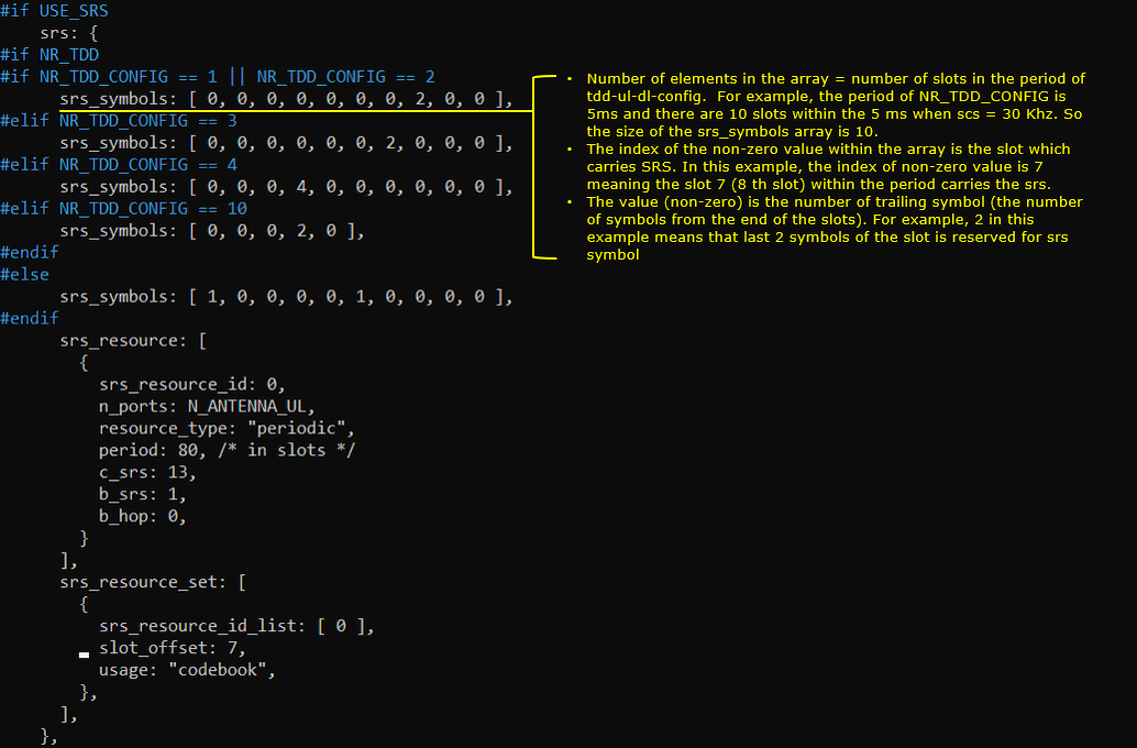
Tips: srs_symbols Array Interpretation
- Understanding the srs_symbols array helps in analyzing which symbols are used for SRS transmission, often auto-configured in auto SRS mode.
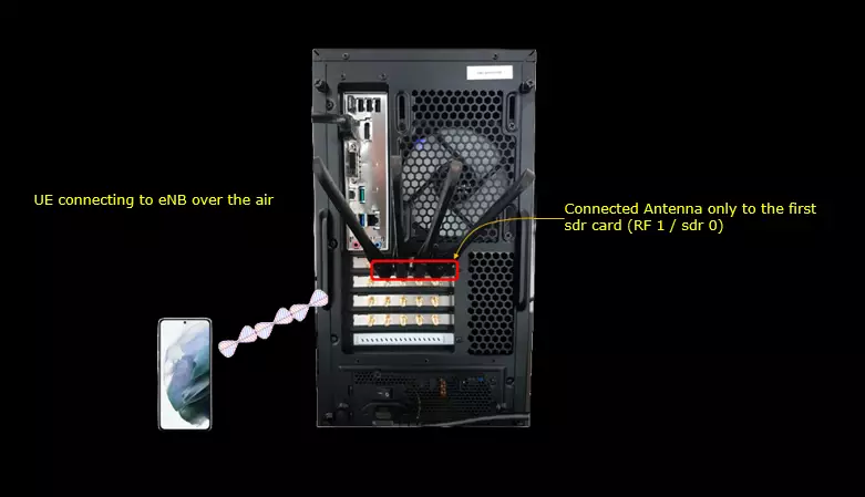
Test Setup
Test setup for this tutorial is as shown below. This is just for low layer testing, you may not need any complicated IP layer setup.
- SIM Card used in this tutorial is the one delivered with the system as it is.
- If you want to change the configuration, The tutorial Configuration Guide would help
Key Configuration Parameters
Followings are important configuration parameters for this tutorial. You may click on the items for the descriptions from Amarisoft documents.
- srs : In this link, you can get the descriptions for all the parameters listed below
- srs_symbols
- srs_resource
- srs_resource_id
- n_ports
- transmission_comb
- cyclic_shift
- n_symb
- repetition_factor
- c_srs
- freq_domain_shift
- b_srs
- b_hop
- group_or_sequence_hopping
- n_id
- resource_type
- period
- srs_resource_set
- srs_resource_set_id
- srs_resource_id_list
- aperiodic_srs_trigger
- slot_offset
- usage
- p0
- alpha
Reference Configuration : Auto SRS Configuration
Configuration
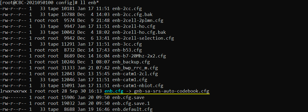
From the release 2022-09-16, the default configuration gnb-sa.cfg itself already configured auto srs, but I copied the gnb-sa.cfg and renamed to gnb-sa-srs-auto-condebook.cfg just because I changed one parameter "#define USE_SRS". (
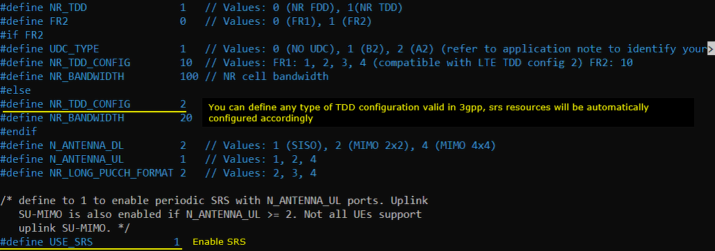
In the configuration file, you can select any specific tdd pattern with the parameter NR_TDD_CONFIG. To apply TDD configuration, you first need to configure the duplex mode (NR_TDD) to 1 (TDD). And then I set NR_TDD_CONFIG to 2 which is one of default sample configuration provided by Amarisoft sample configuration. (
You can configure srs with automatic resource configuration by using the parameter resource_auto within srs object. You only need to configure resource_type and period parameter.

Following table shows an example of srs configuration. You would notice how simple it get with auto SRS configuration. Also you would notice in AutoSRS that you don't see the parts to configure srs_symbols. srs_symbols is automatically configured based on the details of TDD_CONFIG.
|
Configuration without AutoSRSI |
Configuration with AutoSRS |
| This is the configuration in gnb-sa.cfg before AutoSRS feature is supported | This is the configuration in gnb-sa.cfg after AutoSRS feature is supported |
|
#if USE_SRS srs: { #if NR_TDD #if NR_TDD_CONFIG == 1 || NR_TDD_CONFIG == 2 srs_symbols: [ 0, 0, 0, 0, 0, 0, 0, 2, 0, 0 ], #elif NR_TDD_CONFIG == 3 srs_symbols: [ 0, 0, 0, 0, 0, 0, 2, 0, 0, 0 ], #elif NR_TDD_CONFIG == 4 srs_symbols: [ 0, 0, 0, 4, 0, 0, 0, 0, 0, 0 ], #elif NR_TDD_CONFIG == 10 srs_symbols: [ 0, 0, 0, 2, 0 ], #endif #else srs_symbols: [ 1, 0, 0, 0, 0, 1, 0, 0, 0, 0 ], #endif srs_resource: [ { srs_resource_id: 0, n_ports: N_ANTENNA_UL, resource_type: "periodic", period: 80, /* in slots */ c_srs: 13, b_srs: 1, b_hop: 0, } ], srs_resource_set: [ { srs_resource_id_list: [ 0 ], slot_offset: 7, usage: "codebook", }, ], }, #endif |
#if USE_SRS srs: { resource_auto: { codebook: { resource_type: "periodic", period: 80, /* in slots */ } } }, #endif |
Log Analysis
This is just for showing the association between the configuration shown above and IE (Information Elements) in RRC.
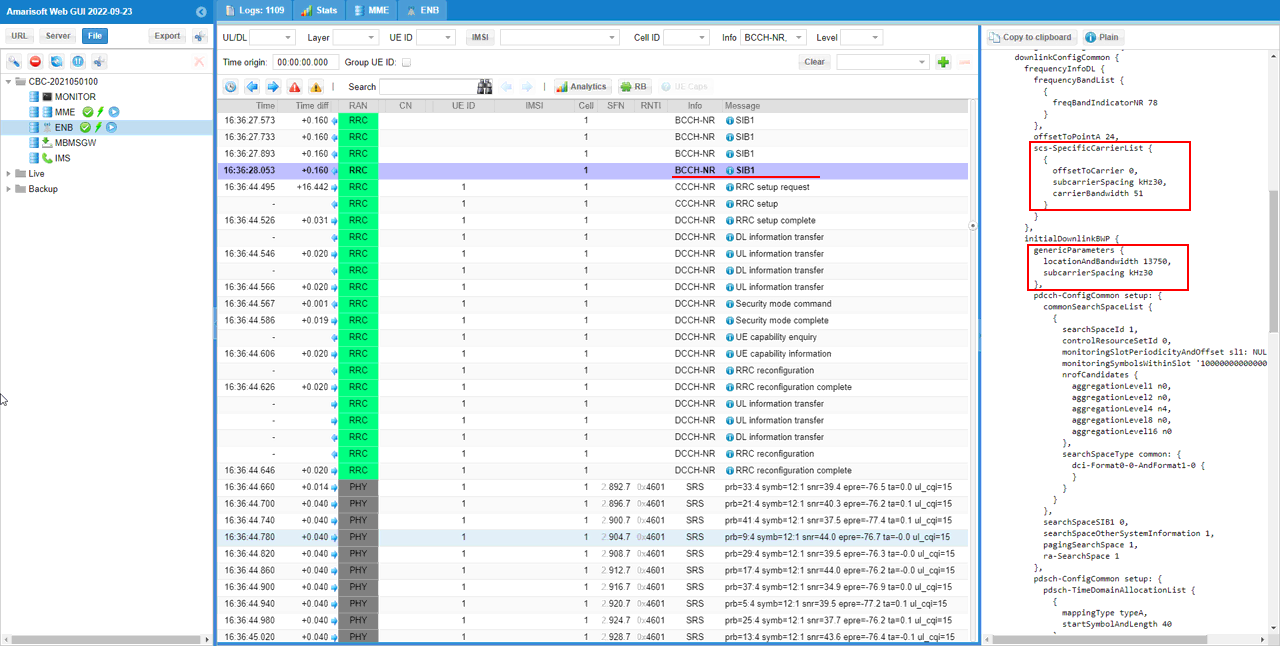
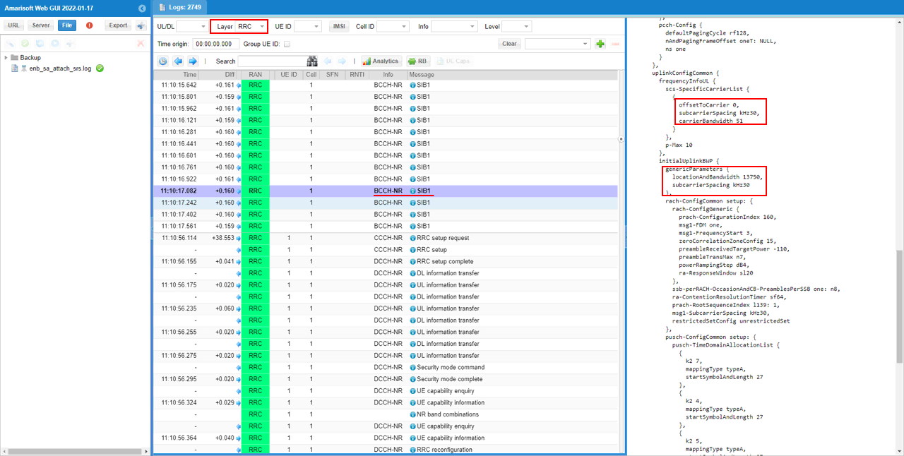
This is not mandated to check but I would check scs-SpecificCarrierList and initialDownlink BWP in SIB1 just to make it sure that enough bandwidth has been allocated for the SRS configuration.
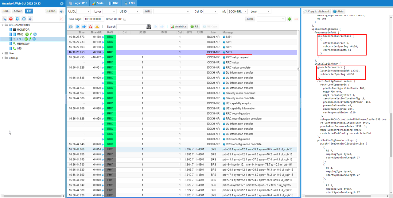
By the same logic, I would check scs-SpecificCarrierList and initialUplink BWP in SIB1 just to make it sure that enough bandwidth has been allocated for the SRS configuration.
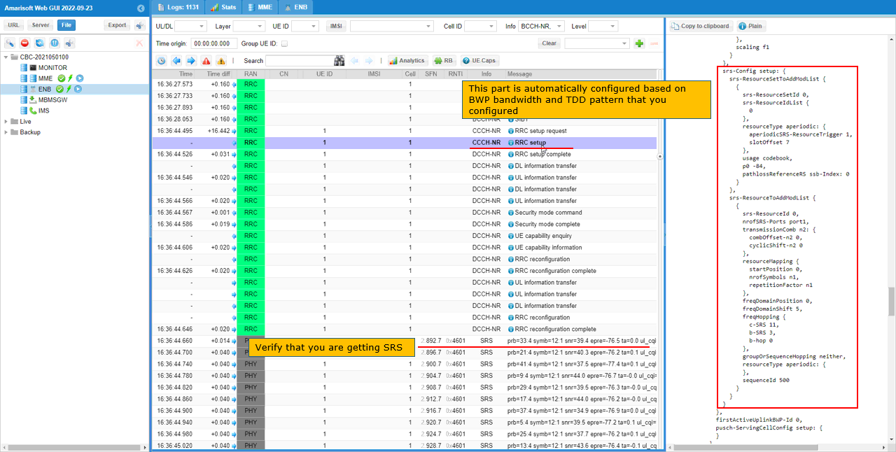
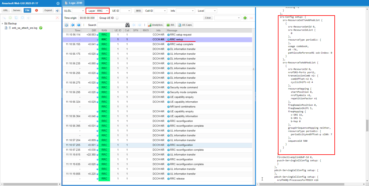
Now check out how rsr-Config is setup in RRC Setup message. This is not your choise of configuration since you used auto confic, but it is good to know how all of these parameters are configured by the auto config. These IEs are configured based on BWP bandwidth and TDD pattern that you configured in configuration file.
Test 1 : Periodic/Codebook SRS
The purpose of this test is to show you how to configured the detailed srs configuration manually. It is a little bit complicated to configure comparing to auto configuration, but the advatage is that you can configure the detailed configuration as you want.
Configuration
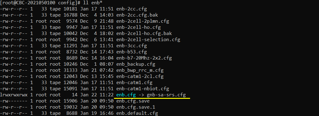
I have used gnb-sa-srs.cfg which is copied and modified from gnb-sa.cfg.
I am using the default mme, ims config as shown below.

In gnb-sa-srs.cfg, I made a modification as follows (this is because the commercial UE that I have support TDD only. You may use whatever configuration that your UE support). Note that I set USE_SRS to 1 to enable SRS configuration.
In the configuration file, you can select any specific tdd pattern with the parameter NR_TDD_CONFIG. To apply TDD configuration, you first need to configure the duplex mode (NR_TDD) to 1 (TDD). And then I set NR_TDD_CONFIG to 2 which is one of default sample configuration provided by Amarisoft sample configuration. (

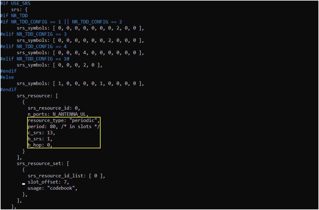
In the tutorial, I will try a couple of tests with the modification to the parameters highlighted below. In default configuration, c_srs, b_srs, b_hop is not configured and the call box will use the default configuration if it is not configured in the configuration file.
NOTE : In the configuration in this release (2022-01-17), resource periodicity slot offset is configured automatically by callbox. It is not user configurable. The slot offset in periodicity is configured differently for each SRS resources depending on the overall cell configuration. You can check up RRC message for the specific slot offset applied for each srs resources.
Main purpose of this test is to configure c_srs, b_srs, b_hop parameter as you like and check how it works. These three parameters are about SRS bandwidth configuration. Check out this note if you are new to SRS bandwidth configuration details.
Perform the Test
Testing process is simple. You only have to do NR SA attach (See NR SA Attach tutorial if you are not familiar with the process). The important part is to check the log and verify if you get the SRS as configured.
Log Analysis
First check RRC log and see if the configuration is done as you intended. In this tutorial, I am checking SIB1 for the channel bandwidth and BWP and RrcSetup for SRS configuration.
You can confirm the srs resource configuration and periodicity including the slot offset in srs-Config IE of RRC Setup message.
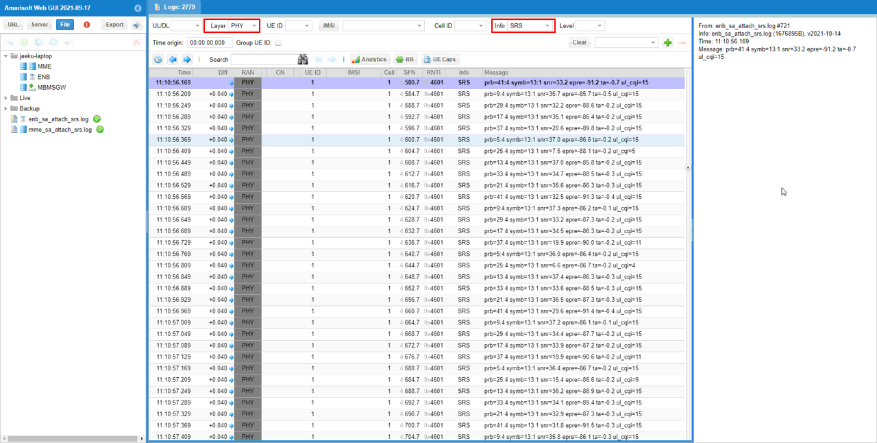
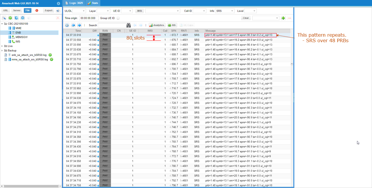
Then after UE attached, you can check the SRS received by the call box. It would be easier for analysis if you set filters as shown below. If you filter out SRS signal only using the [Info] field on WebGUI, you can get all the SRS signals received by gNB. From this, you can check the periodicity of SRS and bandwidth pattern. You can confirm on periodicity from consecutive SFN values and bandwidth pattern from prb field. The prb is printed in the form of prb=S:N, S indicates the starting PRB and N indicates the number of consecutive PRBs for the SRS signal.
Sub Test 1 : SRS with default configuration
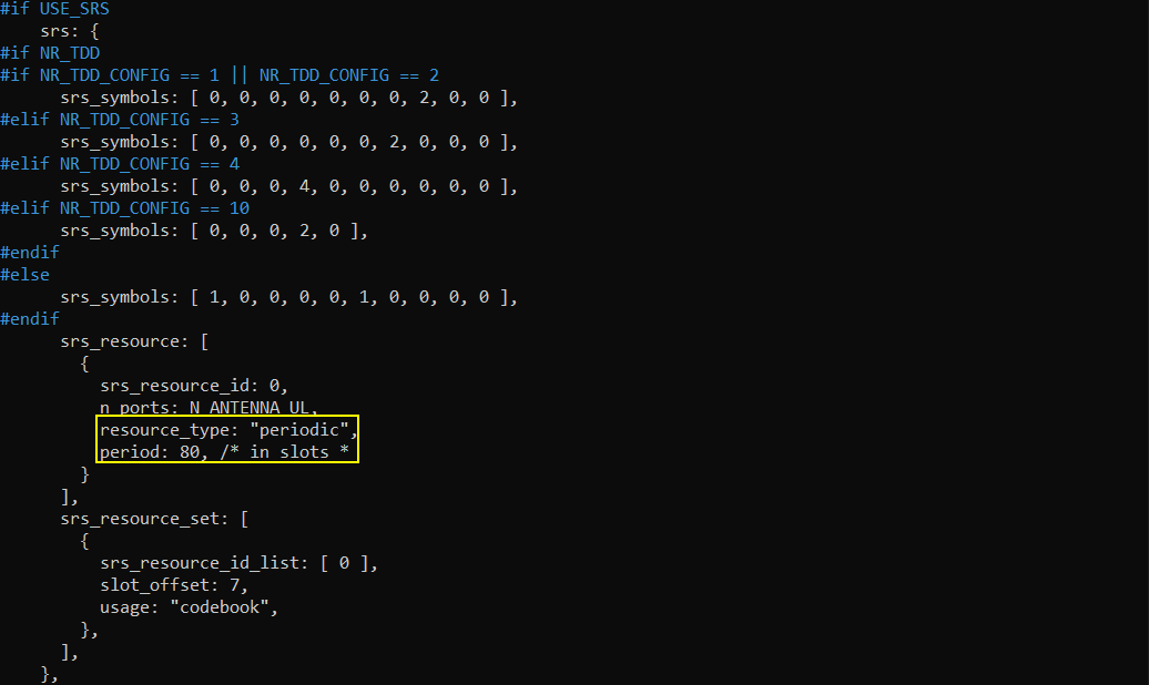
In this test, I set the srs configuration as follows. (
Main purpose of this test is to remove c_srs, b_srs, b_hop parameter and let the callbox apply the default configuration. You can check how the detault SRS bandwidth configuration is configured in this test. These three parameters are about SRS bandwidth configuration. Check out this note if you are new to SRS bandwidth configuration details.
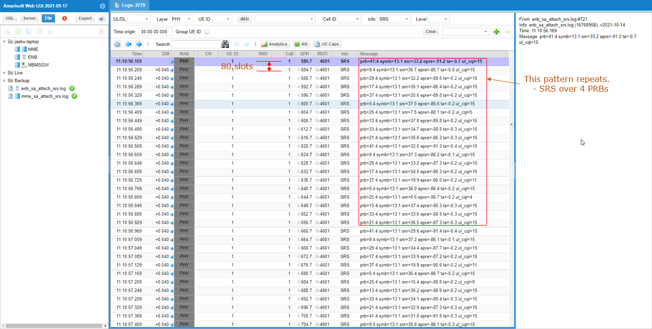
Check if SRS is received with the interval, frequency domain position as you configure. If you filter out SRS signal only using the [Info] field on WebGUI, you can get all the SRS signals received by gNB. From this, you can check the periodicity of SRS and bandwidth pattern. You can confirm on periodicity from consecutive SFN values and bandwidth pattern from prb field. The prb is printed in the form of prb=S:N, S indicates the starting PRB and N indicates the number of consecutive PRBs for the SRS signal.
Sub Test 2 : SRS with c_srs 13, b_srs 1, b_hop 0
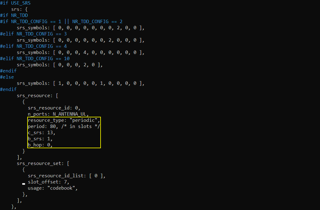
In this test, I set the srs configuration as follows.
Main purpose of this test is to configure another set of c_srs, b_srs, b_hop parameter as you like and check how it works. These three parameters are about SRS bandwidth configuration. Check out this note if you are new to SRS bandwidth configuration details.
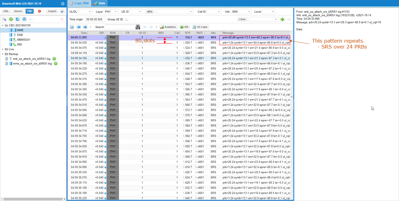
Check if SRS is received with the interval, frequency domain position as you configure. If you filter out SRS signal only using the [Info] field on WebGUI, you can get all the SRS signals received by gNB. From this, you can check the periodicity of SRS and bandwidth pattern. You can confirm on periodicity from consecutive SFN values and bandwidth pattern from prb field. The prb is printed in the form of prb=S:N, S indicates the starting PRB and N indicates the number of consecutive PRBs for the SRS signal.
Sub Test 3 : SRS with c_srs 13, b_srs 0, b_hop 0
In this test, I set the srs configuration as follows.
Main purpose of this test is to configure another set of c_srs, b_srs, b_hop parameter as you like and check how it works. These three parameters are about SRS bandwidth configuration. Check out this note if you are new to SRS bandwidth configuration details.
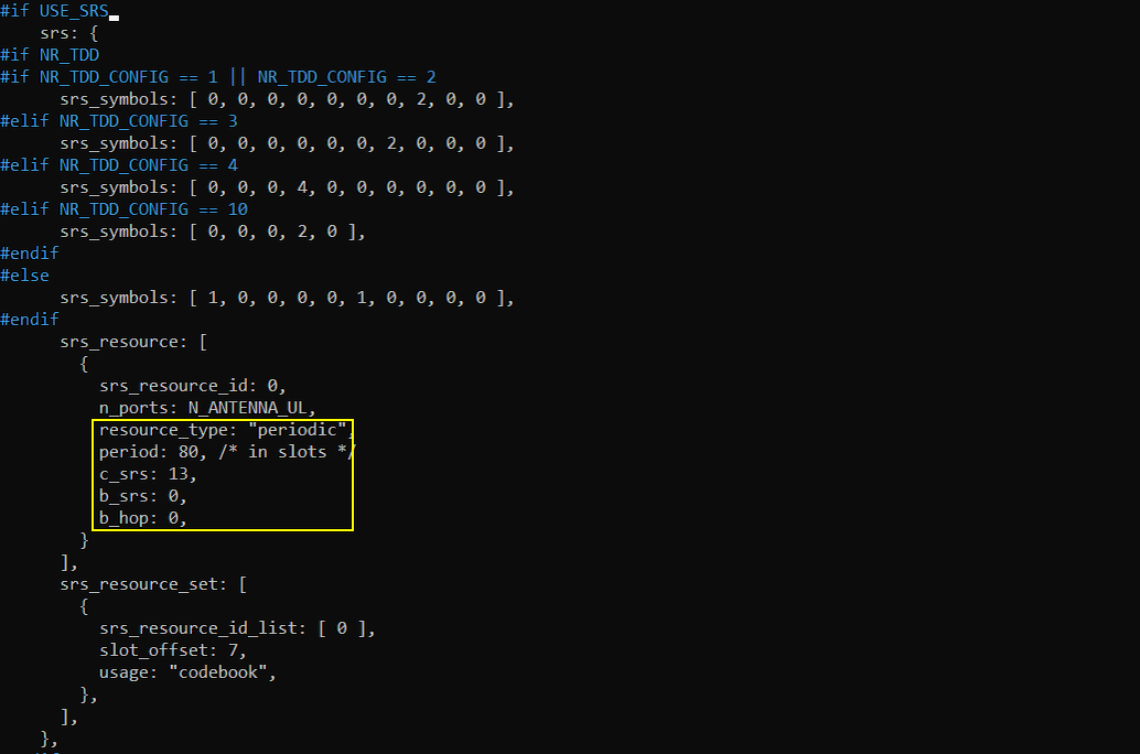
Check if SRS is received with the interval, frequency domain position as you configure. If you filter out SRS signal only using the [Info] field on WebGUI, you can get all the SRS signals received by gNB. From this, you can check the periodicity of SRS and bandwidth pattern. You can confirm on periodicity from consecutive SFN values and bandwidth pattern from prb field. The prb is printed in the form of prb=S:N, S indicates the starting PRB and N indicates the number of consecutive PRBs for the SRS signal.
Test 2 : Aperiodic/Codebook SRS
The purpose of this test is to show how to configure Aperiodic SRS with the usage of codebook and how to verify it from the log. The way how Aperiodic SRS works is that gNB enables SRS request field in DCI 1_1 and UE is supposed to send SRS when it recieves the DCI with SRS Request field is enabled. Exactly when UE is supposed to send SRS (i.e, what is the time gap between DCI and SRS transmission) ? This timegap (offset) is configured in RRC message.
Configuration
I have used gnb-sa-srs-ap.cfg which is copied and modified from gnb-sa.cfg.

I am using the default mme, ims config as shown below.

In gnb-sa-srs-ap.cfg, I made a modification as follows (this is because the commercial UE that I have support TDD only. You may use whatever configuration that your UE support). Note that I set USE_SRS to 1 to enable SRS configuration.
In the configuration file, you can select any specific tdd pattern with the parameter NR_TDD_CONFIG. To apply TDD configuration, you first need to configure the duplex mode (NR_TDD) to 1 (TDD). And then I set NR_TDD_CONFIG to 2 which is one of default sample configuration provided by Amarisoft sample configuration. (

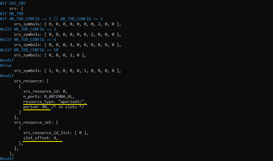
In the tutorial, I will try a couple of tests with the modification to the parameters highlighted below. In default configuration, c_srs, b_srs, b_hop is not configured and the call box will use the default configuration if it is not configured in the configuration file.
Perform the Test
Testing process is simple. You only have to do NR SA attach (See NR SA Attach tutorial if you are not familiar with the process). The important part is to check the log and verify if you get the SRS as configured.
Log Analysis
First check RRC log and see if the configuration is done as you intended. In this tutorial, I am checking SIB1 for the channel bandwidth and BWP and RrcSetup for SRS configuration.
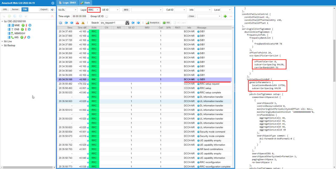
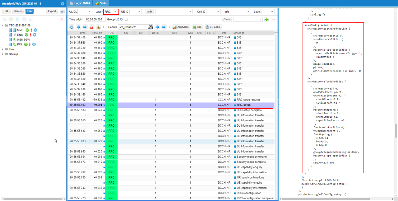
You can confirm the srs resource configuration and periodicity including the slot offset with srs-Config IE in RRC Setup message. You should note that resourceType is set to aperiodic and slotOffset is set to 4 as set in the configuration file. The slotOffset indicates the timegap between SRS Trigger(DCI 1_1 with srs request field enabled) and SRS transmission.
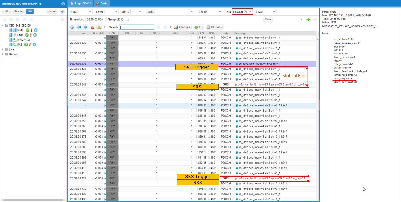
Then after UE attached, you can check the SRS received by the call box. It would be easier for analysis if you set filters as shown below. You see that srs_request is set to 1 (enabled) in DCI field. Check out the time gap between the DCI 1_1(SRS trigger) and the first SRS after the trigger and see if the timegap matches the offset value in RRC.
Test 3 : Periodic/Non-Codebook SRS
The purpose of this test is to show how to configure non-Codebook based SRS and how to verify it from the test log.
Configuration
I have used gnb-sa-srs-noncodebook.cfg which is copied and modified from gnb-sa.cfg.

I am using the default mme, ims config as shown below.

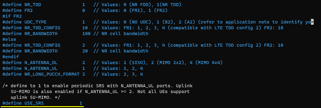
In gnb-sa-srs-noncodebook.cfg I made a modification as follows. Note that I set USE_SRS to 1 to enable SRS configuration.
In the configuration file, you can select any specific tdd pattern with the parameter NR_TDD_CONFIG. To apply TDD configuration, you first need to configure the duplex mode (NR_TDD) to 1 (TDD). And then I set NR_TDD_CONFIG to 2 which is one of default sample configuration provided by Amarisoft sample configuration. (
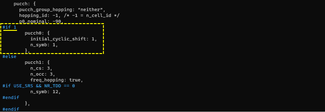
In this test, I am using pucch format 0 instead of pucch 1.
Applying non_codebook configuration is simple. Just use non_codebook parameter instead of codebook parameter.

To apply the non-condebook SRS, you need to set PUSCH tx_config to "non_codebook" as well.
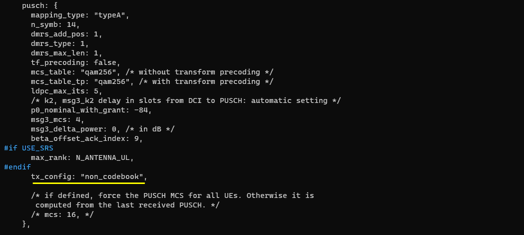
Perform the Test
Testing process is simple. You only have to do NR SA attach (See NR SA Attach tutorial if you are not familiar with the process). The important part is to check the log and verify if you get the SRS as configured.
Log Analysis
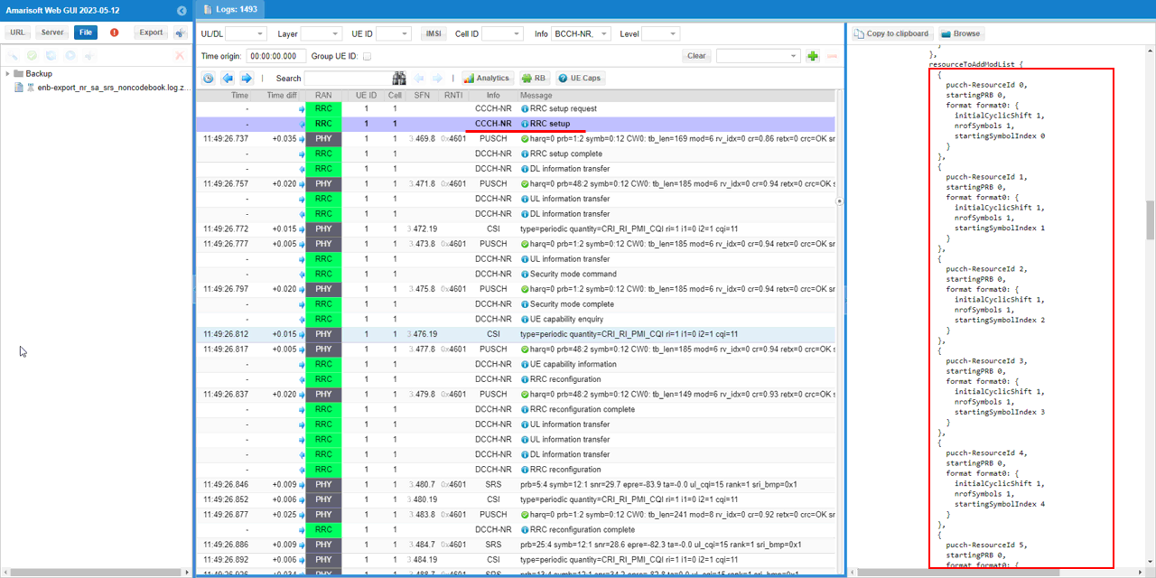
Since we changed pucch format in the configuration file, it would be good to check if the changed configuration is properly applied in the log. Look into RRC Setup message and check if the pucch configuration is changed as you set in the configuration file. I see pucch format 0 is used as I set in the configuration file.
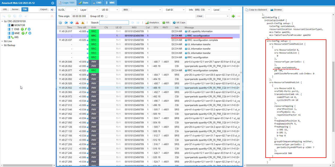
Now check out srs-Config in RRC Reconfiguration and you should see the srs usage is set to nonCodebook in the srs resourceSet in srs-ResourceSetToAddModList.
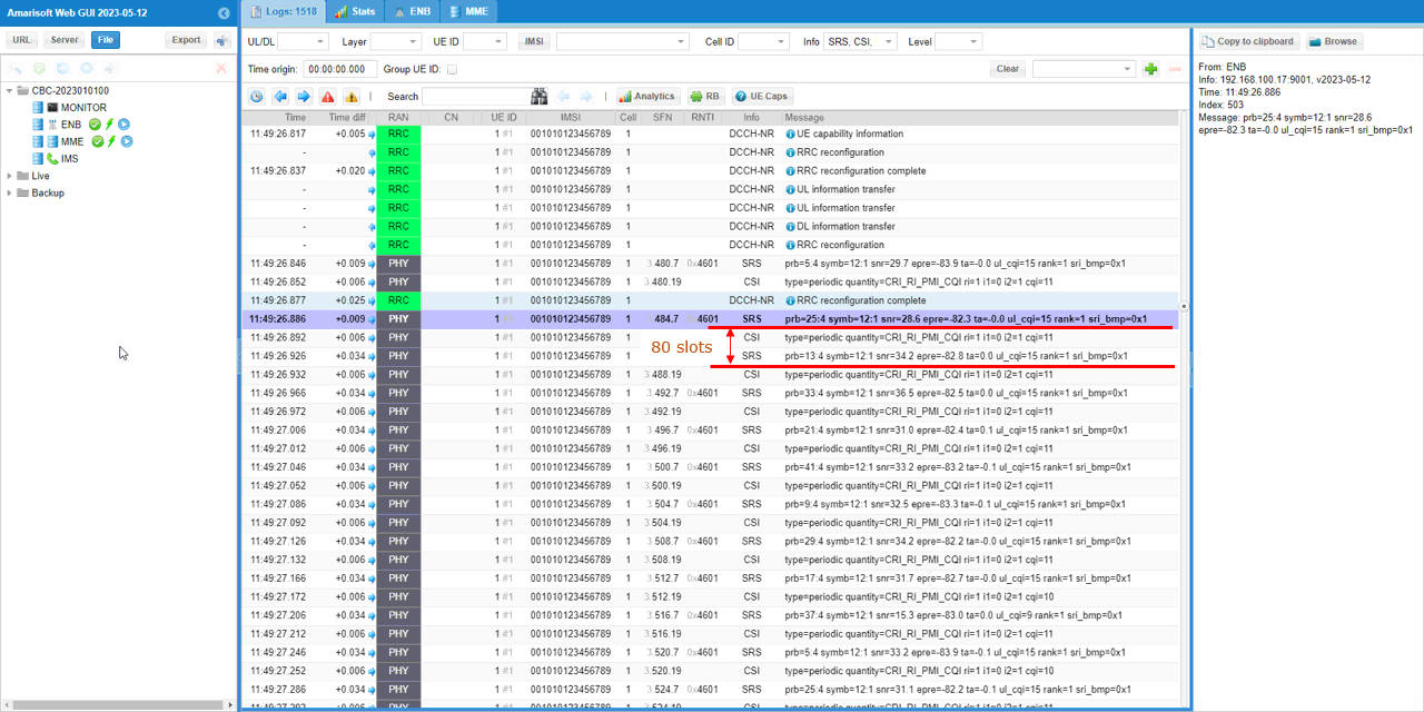
Once the configuration in RRC is properly set and the connection is established, you should be able to see SRS reception. Filter out SRS (and/or CSI) in [Info] field for easy analysis and confirm on SRS reception timing and periodicity with SFN.
RRC / NAS Signaling
RrcSetup (SA)
: This is the RrcSetup message sent by gNB to configure NR SA. (
message c1: rrcSetup: {
rrc-TransactionIdentifier 0,
criticalExtensions rrcSetup: {
radioBearerConfig {
...
},
masterCellGroup {
...
},
mac-CellGroupConfig {
...
},
physicalCellGroupConfig {
pdsch-HARQ-ACK-Codebook dynamic
},
spCellConfig {
spCellConfigDedicated {
initialDownlinkBWP {
pdcch-Config setup: {
...
},
pdsch-Config setup: {
...
},
firstActiveDownlinkBWP-Id 0,
uplinkConfig {
initialUplinkBWP {
pucch-Config setup: {
...
},
pusch-Config setup: {
...
},
srs-Config setup: {
srs-ResourceSetToAddModList {
{
srs-ResourceSetId 0,
srs-ResourceIdList {
0
},
resourceType aperiodic: {
aperiodicSRS-ResourceTrigger 1,
slotOffset 4
},
usage codebook,
p0 -84,
pathlossReferenceRS ssb-Index: 0
}
},
srs-ResourceToAddModList {
{
srs-ResourceId 0,
nrofSRS-Ports port1,
transmissionComb n2: {
combOffset-n2 0,
cyclicShift-n2 7
},
resourceMapping {
startPosition 1,
nrofSymbols n1,
repetitionFactor n1
},
freqDomainPosition 0,
freqDomainShift 5,
freqHopping {
c-SRS 11,
b-SRS 3,
b-hop 0
},
groupOrSequenceHopping neither,
resourceType aperiodic: {
},
sequenceId 500
}
}
}
},
firstActiveUplinkBWP-Id 0,
pusch-ServingCellConfig setup: {
}
},
pdcch-ServingCellConfig setup: {
},
pdsch-ServingCellConfig setup: {
nrofHARQ-ProcessesForPDSCH n16,
maxMIMO-Layers 2
},
csi-MeasConfig setup: {
...
},
tag-Id 0
}
Tips
Interpretation of srs_symbols array
