Remote API - PHY/MAC
This tutorial shows you how to change configurations for PHY/MAC with Remote API while the lte service is running. (
You can do set these configurations in configuration file, but if you use the configuration file you need to stop the lte service and change the value and run again when you want to change those parameter values. But if you are using Remote API, you can change those parameter values without stopping lte service.
I personally use this kind of tricks to figure out the root cause of BLER (low throughput) and troubleshoot the high BLER issue. Whenever I have the case where I am getting high BLER, I usually do as follows:
Step 1 : set full schedulinging force_dl_schedule and force_full_bsr and set very low mcs
Step 2 : check if you still see high bler even at the very low MCS, if you don't see high BLER at low MCS, increase MCS step by step during run time using the Remote API and find the first MCS that is causing high BLER.
Step 3 : Adjust radio link (e.g, cabling, distance between UE and Callbox Antenna etc) and repeat step 2 until you see any improvement.
Table of Contents
Introduction
The ability to dynamically configure PHY (Physical Layer) and MAC (Medium Access Control) parameters in an LTE (Long Term Evolution) environment is a crucial aspect of modern telecom system management, particularly in scenarios where uptime and service continuity are paramount. Traditional approaches require halting the LTE service to modify configuration files, leading to service interruptions and operational inefficiencies. The Remote API framework addresses this limitation by enabling real-time parameter adjustments without necessitating a service restart. Architecturally, the Remote API acts as an abstraction layer, interfacing with the LTE stack and exposing a set of programmable endpoints that allow for the modification of key runtime parameters such as scheduling strategies, MCS (Modulation and Coding Scheme), and buffer settings. This flexibility is vital for troubleshooting and optimizing radio performance metrics like BLER (Block Error Rate) and throughput, especially in live network environments. By leveraging the Remote API, engineers gain granular control over the radio interface, allowing iterative tuning and rapid feedback cycles—a critical capability for diagnosing, mitigating, and resolving radio link issues in both lab and production settings. The Remote API thus plays an integral role in the LTE ecosystem, bridging the gap between static configuration and agile, adaptive network management, and empowering users to maintain optimal service quality with minimal disruption.
-
Context of the Tutorial
- This tutorial focuses on using the Remote API to make real-time adjustments to PHY/MAC configurations in an LTE system while the lte service remains operational.
- The Remote API provides seamless, programmatic access to runtime parameters, eliminating the need for service restarts and supporting advanced troubleshooting and optimization practices.
- Dynamic configuration is particularly valuable for diagnosing and resolving radio interface issues, such as high BLER, in both testing and live deployment scenarios.
-
Relevance and Importance
- Enables efficient network performance tuning without downtime, which is essential for continuous service delivery.
- Supports rapid experimentation and root cause analysis by allowing real-time parameter changes and immediate observation of effects.
- Facilitates advanced troubleshooting workflows for radio link issues, significantly enhancing diagnostic capabilities.
-
Learning Outcomes
- Understand the architectural principles and operational benefits of the Remote API in LTE environments.
- Gain practical skills in modifying PHY/MAC parameters on-the-fly without disrupting active LTE services.
- Develop effective troubleshooting strategies for identifying and resolving BLER and throughput issues using dynamic configuration techniques.
-
Prerequisite Knowledge and Skills
- Familiarity with LTE network architecture, especially PHY and MAC layer concepts.
- Basic understanding of telecom configuration management and performance diagnostics.
- Prior exposure to Remote API usage is recommended for seamless progression through this tutorial. New users should first review the introductory tutorial on Remote API fundamentals.
Summary of the Tutorial
This tutorial demonstrates procedures for low-layer LTE testing, focusing on dynamically changing PHY/MAC configurations for both downlink (DL) and uplink (UL) using Amarisoft Remote API commands. The tests are designed to modify resource allocation and scheduling parameters for a connected UE in a controlled callbox environment, with a focus on practical command execution and verification.
-
Test 1: Changing DL PHY Configurations
-
Before powering on the UE, the inactivity_timer is extended via Remote API to maintain RRC connection throughout the test. This prevents premature release due to inactivity, as higher-layer traffic is not generated.
./ws.js enb '{"message":"config_set","cells":{"1":{"inactivity_timer":6000}}}' -
Change the pdsch_mcs parameter to modify the DL modulation and coding scheme for the specified cell. This demonstrates the ability to set DL transport block parameters in real time.
./ws.js enb '{"message":"config_set","cells":{"1":{"pdsch_mcs":2}}}' -
Verify parameter changes using the trace log (
tcommand), ensuring the updated configuration is in effect. -
Enable forced DL scheduling by setting force_dl_schedule to true, resulting in the eNB attempting to schedule PDSCH in every possible subframe.
./ws.js enb '{"message":"config_set","cells":{"1":{"force_dl_schedule":true}}}' -
Adjust the PDSCH resource block (RB) allocation to a fixed range by setting pdsch_fixed_rb_alloc to true, specifying the start and length of the RB allocation.
./ws.js enb '{"message":"config_set","cells":{"1":{"pdsch_fixed_rb_alloc":true,"pdsch_fixed_rb_start":0,"pdsch_fixed_rb_l_crb":20}}}' -
Use the
tcommand on the eNB to confirm the correct application of all configuration changes.
-
Before powering on the UE, the inactivity_timer is extended via Remote API to maintain RRC connection throughout the test. This prevents premature release due to inactivity, as higher-layer traffic is not generated.
-
Test 2: Changing UL PHY Configurations
-
As in Test 1, extend the inactivity_timer before UE power-on to maintain the connection.
./ws.js enb '{"message":"config_set","cells":{"1":{"inactivity_timer":6000}}}' -
Change the pusch_mcs parameter to alter the UL modulation and coding scheme for the specified cell.
./ws.js enb '{"message":"config_set","cells":{"1":{"pusch_mcs":2}}}' -
Confirm the parameter update using the trace log (
tcommand). -
Enable forced BSR reporting by setting force_full_bsr to true, triggering the eNB to schedule uplink grants more aggressively.
./ws.js enb '{"message":"config_set","cells":{"1":{"force_full_bsr":true}}}' -
Again, verify the updated configuration via the
tcommand on the eNB.
-
As in Test 1, extend the inactivity_timer before UE power-on to maintain the connection.
Methodology Overview:
- Key configuration parameters are adjusted live via the Amarisoft Remote API, without modifying the static configuration files.
- Each configuration change is specific to a cell (e.g., cell ID 1) and is applied via JSON-formatted command-line instructions.
- Verification of parameter changes is performed by monitoring the trace output (
tcommand) to ensure the desired settings are active. - The procedure is modular, allowing for further parameter experimentation once the basic method is understood.
Test Setup
Test setup for this tutorial is as shown below. This is just for low layer testing, you may not need any complicated IP layer setup.
- SIM Card used in this tutorial is the one delivered with the system as it is.
- If you want to change the configuration, The tutorial Configuration Guide would help
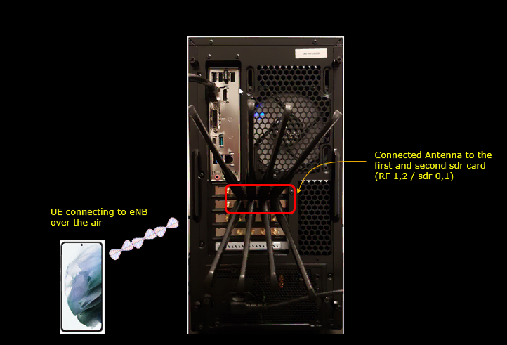
I used a UE communicating over the radio link with the callbox. The external antennas connect to the two SDR boards.
Key Configuration Parameters
Followings are important configuration parameters for this tutorial. You may click on the items for the descriptions from Amarisoft documents.
- force_dl_schedule
- force_full_bsr
- pdsch_mcs
- pusch_mcs
- inactivity_timer
- pdsch_fixed_rb_alloc
- pdsch_fixed_rb_start
- pdsch_fixed_l_crb
- pusch_fixed_rb_alloc
- pusch_fixed_rb_start
- pusch_fixed_l_crb
Configuration
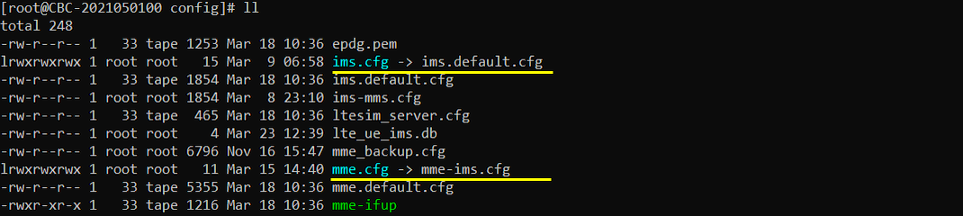
In this tutorial, the default configuration (the default configuration for LTE) is used without any change. We don't need to change anything in the configuration file since we will change configuration using Remote API while the lte service is running

Test 1 : Changing DL PHY Configurations
In this test, I will change some parameters to change resource allocation and scheduling for LTE DL. This is just an example of changing DL PHY/MAC configuration. You don't need to do exactly as shown here. Once you get familiar with this basic operation, you may use any other parameters in any order as you like.
Perform the Test
Before power on UE, I extended the inactivity_timer as shown below to maitain the call connection during the whole test period. Since I am not generating any higher layer traffic (e.g, IP traffic), if you don't extend inactivity_timer, RRC will be released soon (10 seconds by default) after the initial attach.
./ws.js enb '{"message":"config_set","cells":{"1":{"inactivity_timer":6000}}}'
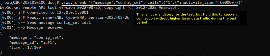
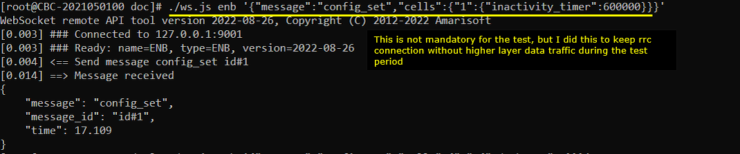
For this run, I set inactivity_timer to 600000 for cell 1. The timer is in milliseconds, so this value gives 600 seconds of network inactivity before RRC release.
This extension is optional. I used it to keep the RRC connection during the test without higher layer data traffic. The ws.js client connects to 127.0.0.1:9001 and receives a config_set response.
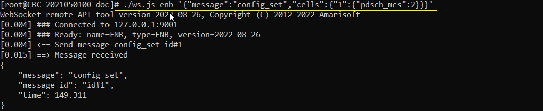
Try changing pdsch mcs using the following command. (
./ws.js enb '{"message":"config_set","cells":{"1":{"pdsch_mcs":2}}}'
I set pdsch_mcs to 2 inside the cells object for cell 1. The response returns message: "config_set" and message_id: "id#1" without an error field.
You can change pdsch_mcs to try another downlink MCS. Check the DL mcs column in the trace after each change.
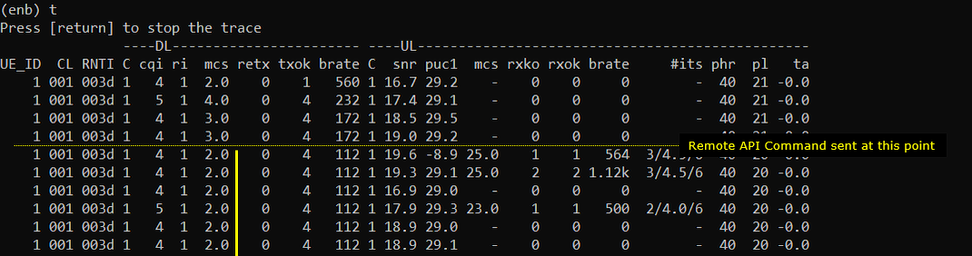
Check if the command is properly applied using 't' command as shown below. (
Before the command, the DL mcs values include 4.0 and 3.0. After the command, the displayed DL mcs stays at 2.0 for UE_ID 1 and RNTI 003d.
The later rows report DL retx as 0 and txok as 4. The UL mcs column contains separate uplink results, so use the DL column for this check.
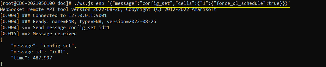
Now I am trying to let eNB to schedule pdsch at every possible subframe using the command as shown below. (
./ws.js enb '{"message":"config_set","cells":{"1":{"force_dl_schedule":true}}}'
With force_dl_schedule set to true, the eNodeB considers downlink data to be waiting for transmission. It then schedules the UE as often as possible for PDSCH transmission.
I sent this setting to cell 1 and received a config_set response. Set force_dl_schedule to false when you want to stop forcing downlink scheduling.
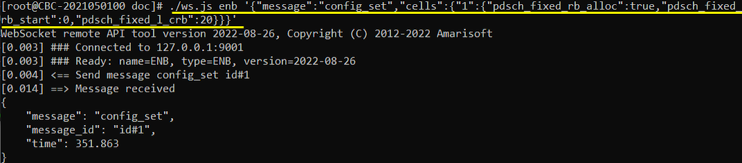
Then change RB ranges for every pdsch using the command as shown below. (
./ws.js enb '{"message":"config_set","cells":{"1":{"pdsch_fixed_rb_alloc":true,"pdsch_fixed_rb_start":0,"pdsch_fixed_rb_l_crb":20}}}'
I enabled pdsch_fixed_rb_alloc and set pdsch_fixed_rb_start to 0. The allocation length parameter used in this run is pdsch_fixed_l_crb, set to 20.
This selects 20 consecutive RBs starting at RB 0. You can change the start and length to test a different fixed allocation.
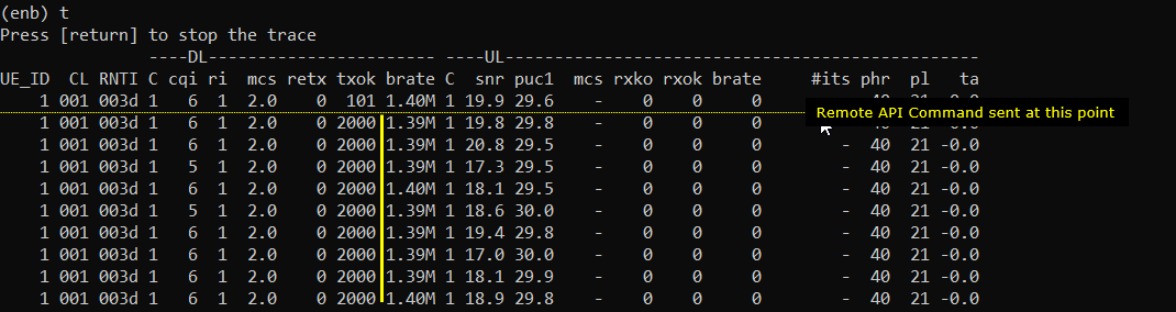
Check if the command is properly applied using 't' command as shown below
The DL mcs remains at 2.0, while txok reaches 2000 in the later rows. The DL brate stays around 1.39M to 1.40M, and retx remains 0.
This trace lets you check the resulting downlink activity. It does not list the RB start or allocation length directly.
Test 2 : Changing UL PHY Configurations
In this test, I will change some parameters to change resource allocation and scheduling for LTE UL. This is just an example of changing UL PHY/MAC configuration. You don't need to do exactly as shown here. Once you get familiar with this basic operation, you may use any other parameters in any order as you like.
Perform the Test
Before power on UE, I extended the inactivity_timer as shown below to maitain the call connection during the whole test period.
./ws.js enb '{"message":"config_set","cells":{"1":{"inactivity_timer":6000}}}' (
For the uplink run, I also used inactivity_timer: 600000 for cell 1. This is 600 seconds because the parameter uses milliseconds.
The timer change is optional and keeps the connection available without higher layer data traffic during the test. The client receives a config_set response from the eNB at 127.0.0.1:9001.
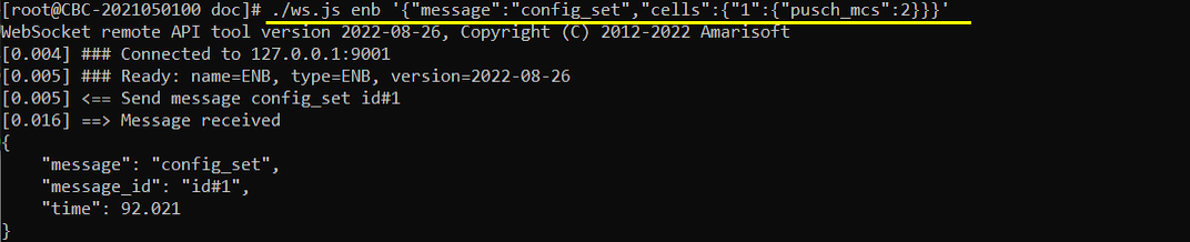
Try changing pusch mcs using the following command.
./ws.js enb '{"message":"config_set","cells":{"1":{"pusch_mcs":2}}}' (
I set pusch_mcs to 2 for cell 1. The eNB returns a config_set response with message_id: "id#1" and no error field.
Use the UL mcs column to check this change. You can try another pusch_mcs value and compare the uplink results.
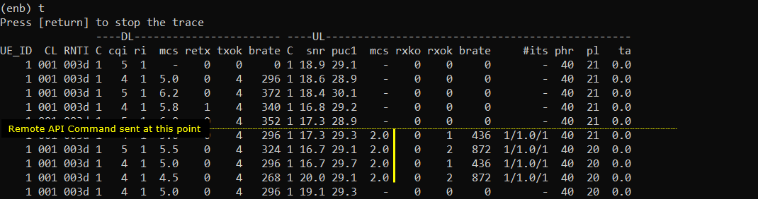
Check if the command is properly applied using 't' command as shown below.
After the command, the UL mcs is 2.0 on the rows with uplink transmissions. The UL rxok values are 1 or 2, and rxko remains 0 on those rows.
The UL brate values include 436 and 872. Rows without uplink transmissions display a dash in the UL mcs column.
Now I am trying to let eNB to schedule pdsch at every possible subframe using the command as shown below.
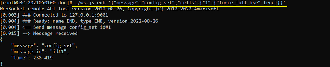
./ws.js enb '{"message":"config_set","cells":{"1":{"force_full_bsr":true}}}' (
I set force_full_bsr to true for cell 1. This makes the eNodeB treat the UE buffer as full and schedule PUSCH as often as possible.
The response contains message: "config_set" and message_id: "id#1". Set force_full_bsr to false when you want to stop forcing the full buffer assumption.
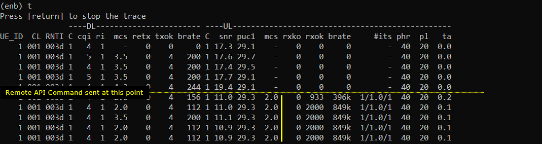
Check if the command is properly applied using 't' command as shown below.
After enabling force_full_bsr, UL rxok first reaches 933 and then 2000 in the later rows. UL brate rises from 396k to 849k, while UL mcs remains 2.0.
The later rows report UL rxko as 0. Compare these uplink columns with the sparse transmissions before forcing the full buffer assumption.