NR SA PUCCH
The purpose of this tutorial is to show you how to configure PUCCH and associate the configuration to pucch related IE(informatin elements) in RRC message (e.g, SIB1, RRC Setup) and analyze the log to figure out which physical resources are used for each PUCCH.
Table of Contents
Introduction
Physical Uplink Control Channel (PUCCH) plays a pivotal role in 5G NR (New Radio) networks, facilitating the transmission of critical uplink control information (UCI) such as Hybrid Automatic Repeat Request (HARQ) acknowledgements, scheduling requests, and channel state information from User Equipment (UE) to the gNB (next-generation NodeB). The configuration of PUCCH is governed by a set of parameters defined within the 3GPP RRC (Radio Resource Control) framework and is disseminated through RRC signaling messages, including SIB1 and RRC Setup. This architectural approach allows for dynamic adaptation of uplink control resource allocation, optimizing radio resource usage and supporting diverse service requirements. Understanding the interplay between PUCCH configuration, its representation in RRC signaling, and its manifestation in physical resource allocation is essential for engineers and network analysts aiming to optimize network performance, troubleshoot connectivity issues, or perform advanced protocol analysis. The significance of PUCCH configuration extends beyond basic parameter setting; it requires a comprehensive grasp of 3GPP technical specifications, meticulous log analysis, and the ability to correlate configuration files with live RRC message elements during network operation. By mastering these concepts, practitioners can ensure efficient uplink control communication, improve network reliability, and contribute to the broader advancement of 5G technology.
-
Technology Context
- PUCCH is an integral component of the 5G NR uplink, responsible for carrying uplink control information between UE and gNB.
- Configuration of PUCCH involves both physical layer parameterization and higher-layer signaling via RRC messages.
- RRC messages such as SIB1 and RRC Setup serve as the primary conduit for delivering PUCCH-related information elements (IEs) to UEs.
-
Relevance and Importance
- Correctly configuring PUCCH ensures reliable communication of critical control information, directly impacting network performance and user experience.
- Associating configuration files with corresponding RRC message elements is essential for network optimization, troubleshooting, and protocol compliance.
- An in-depth understanding of PUCCH configuration supports effective log analysis, enabling engineers to verify and validate resource assignments in live networks.
-
Tutorial Objectives
- Guide learners through the process of configuring PUCCH parameters in the network configuration file.
- Demonstrate how to map configured parameters to their respective information elements in RRC signaling messages.
- Teach log analysis techniques for identifying and interpreting physical resource allocations for PUCCH in real network scenarios.
-
Learning Outcomes
- Acquire the skills to configure PUCCH and relate configuration settings to RRC message content.
- Develop proficiency in analyzing protocol logs to determine how physical resources are utilized for each PUCCH instance.
- Gain insights into the broader 3GPP NR architecture and the role of uplink control channels in modern mobile networks.
-
Prerequisite Knowledge
- Familiarity with 5G NR architecture and protocol stack, especially RRC and physical layer concepts.
- Understanding of 3GPP specification documents related to PUCCH (e.g., TS 38.211, TS 38.213, TS 38.331).
- Basic experience with network configuration files and protocol log analysis tools.
- For those new to PUCCH, it is recommended to review foundational materials such as the PUCCH primer before proceeding.
Summary of the Tutorial
This tutorial focuses on low layer testing of PUCCH (Physical Uplink Control Channel) configuration and log analysis in a 5G NR Standalone (SA) environment utilizing Amarisoft gNB and UEs. The procedures are structured around a default configuration using gnb-sa.cfg and emphasize practical steps, configuration parameters, and methodologies for both single and multiple UE test scenarios.
-
Test Setup:
- Use the SIM card delivered with the system.
- Minimal IP layer setup required since focus is on low layer testing.
- Diagram provided to illustrate basic connectivity between test equipment and UE.
-
Key Configuration Parameters:
- Parameters such as pucch_resource_common, pucch_group_hopping, hopping_id, p0_nominal, dpc_snr_target, short_pucch_an_rsc_count, long_pucch_an_rsc_count, and others are important for controlling PUCCH behavior.
- Detailed sub-parameters for each PUCCH format (0–4) are highlighted for reference and tuning.
-
Test 1: Default Configuration - Single UE
-
Configuration:
- Default configuration from gnb-sa.cfg used for all subtests.
- NR_TDD_CONFIG set to 2 (for TDD operation), NR_BANDWIDTH to 20MHz, and 2x2 MIMO (N_ANTENNA_DL = 2).
- Band is set to n78 (TDD band), with SSB and CSI-RS configured to avoid collision.
- PUCCH format 1 (short) and format 2 (long) used by default, with key parameters:
- n_cs: Controls the number of initialCyclicShift values distributed across [0,11].
- n_occ: Indicates the range for timeDomainOCC.
- freq_hopping: Enables/disables frequency hopping.
- n_symb: Number of OFDM symbols for PUCCH format 1 (default 14 for TDD and USE_SRS=0).
-
Performing the Test:
- Verify cell configuration using cell phy and cell commands.
- Power on UE, ensure successful attach, and initiate traffic.
-
Log Analysis:
- PUCCH configuration can be found in both SIB1 and RRC Setup messages.
- SIB1 logging is enabled via BCCH, MIB, and CSI options for a short period to avoid excessive logs.
- PUCCH resources are automatically assigned by gNB, with defaults of 8 resources for ResourceSetId 0 and 4 for ResourceSetId 1 (editable via short_pucch_an_rsc_count and long_pucch_an_rsc_count).
- For PUCCH format 1, only freq_hopping is directly mapped to RRC; n_cs and n_occ impact RRC indirectly by determining the number and distribution of resource elements.
- A lookup table is constructed to map log entries to specific PUCCH resource configurations, facilitating quick identification during log analysis.
- Examples demonstrate matching log information (e.g., format, startingPRB, nrofSymbols) to the configuration table for resource identification.
- RB maps can be plotted to visualize PUCCH resource allocation across PRBs and symbols for high-level overview.
-
Configuration:
-
Sub Test 1: Default Configuration - Multiple UE
-
Objective and Configuration:
- Same PUCCH configuration as in single UE test, but with multiple UEs (e.g., 5) connected to gNB.
- The test aims to create higher demand for PUCCH, causing the gNB to utilize more diverse PUCCH resources in DCI 1_x scheduling.
- Multiple UEs are emulated using Amarisoft UEsim or commercial UEs.
-
Log Analysis Approach:
- PUCCH resource identification is performed by correlating pucch_rsc and harq_feedback_timing fields in DCI with the RRC resource sets and the lookup table.
- For each DCI in the log:
- Determine the resource set index from pucch_rsc.
- Map harq_feedback_timing to the proper slot via dl-DataToUL-ACK table.
- Find the physical PUCCH resource by cross-referencing with the configuration lookup table.
- RB map visualization is again used for high-level assessment of resource distribution.
-
Objective and Configuration:
-
General Methodologies and Best Practices:
- Emphasis on using lookup tables to simplify log analysis and avoid repeatedly parsing detailed RRC messages.
- Strategic enabling/disabling of logging options to keep logs manageable and focused.
- RB mapping for visual confirmation of PUCCH resource allocation.
- Understanding the relationship between configuration parameters and resource element mapping is key for accurate analysis.
Note: While specific SIB1 and RRC Setup message examples are provided in the tutorial, the summary above focuses on the procedures, configuration steps, and analysis methodologies, as required.
Test Setup
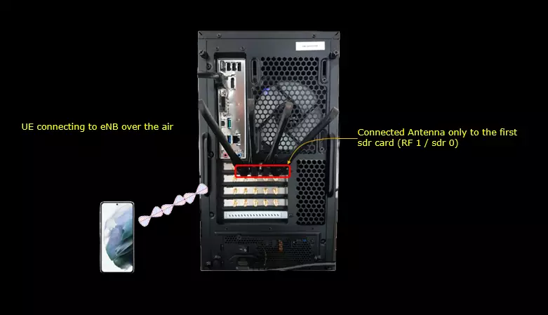
Test setup for this tutorial is as shown below. This is just for low layer testing, you may not need any complicated IP layer setup.
- SIM Card used in this tutorial is the one delivered with the system as it is.
- If you want to change the configuration, The tutorial Configuration Guide would help
Key Configuration Parameters
Followings are important configuration parameters for this tutorial. You may click on the items for the descriptions from Amarisoft documents.
- pucch
- pucch_resource_common
- pucch_group_hopping
- hopping_id
- p0_nominal
- dpc_snr_target
- dpc_epre_max
- short_pucch_an_rsc_count
- long_pucch_an_rsc_count
- ue_short_pucch_an_rsc_count
- ue_long_pucch_an_rsc_count
- pucch02_min_start_symb
- multi_csi
- pucch0
- pucch1
- pucch2
- pucch3
- bpsk
- additional_dmrs
- freq_hopping
- start_symb
- n_symb
- max_code_rate
- simultaneous_harq_ack_csi
- n_prb
- n_prb_csi
- pucch4
Test 1 : Default Configuration - Single UE
In this test, I am trying to show you how to interpret each of the configuration parameters from default setting(gnb-sa.cfg) and how to correlate the configuration with IE(information elements) in RRC messages. In other words, the purpose of this test is to provide the detailed meaning of the pucch configuration parameter and associated RRC IE (information elements).
Configuration
The configuration shown here is common configuration for all the subtests belonging to Test 1 and I will not show this configuration repeatedly for every subtest.
I have used gnb-sa.cfg which is one of the default configuration provided by the installation package.

I am using the default mme, ims config as shown below.

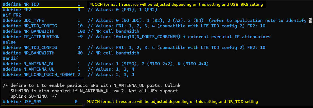
In gnb-sa.cfg , it is configured as follows.
In the configuration file, you can select any specific tdd pattern with the parameter NR_TDD_CONFIG. To apply TDD configuration, you first need to configure the duplex mode (NR_TDD) to 1 (TDD). And then I set NR_TDD_CONFIG to 2 which is one of default sample configuration provided by Amarisoft sample configuration. And I set the channel bandwidth (NR_BANDWIDTH) to 20Mhz and 2x2 MIMO (N_ANTENNA_DL = 2)
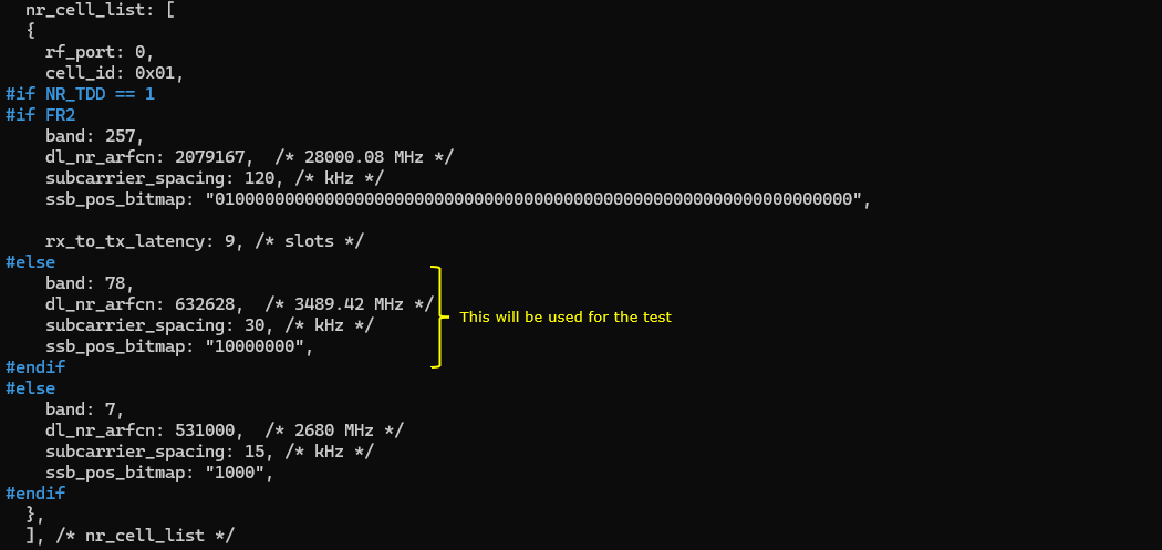
Here the band is set to n78 which is a TDD band. The important part is ssb_pos_bitmap. In this test, only ssb 0 is enabled and all the csi-rs is configured not to collide with the ssb 0 symbols. This is not so important for this test and just use the default settings as it is.
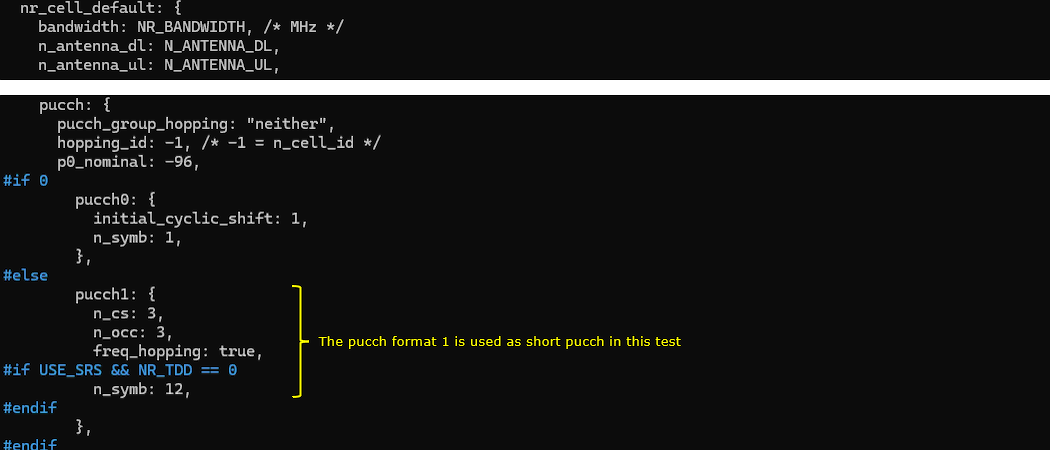
In this test, pucch format 1 is used as the short pucch. You would need to some effort to understand the meaning of each parameter because some parameter (e.g, n_cs, n_occ) are a little tricky to understand. High level descriptions on the parameters set in this configuration is as follows :
- n_cs : this is related to initialCyclicShift in RRC, but this does not indicates the value of initialCyclicShift but the number of different initialCyclicShift values that will be configured in RRC
- n_cs: 2 => two different initialCyclicShift values with interval of 6 within the range of [0,11]. For example, it may use 1 and 7 as initialCyclicShift values
- n_cs: 3 => three different initialCyclicShift values with interval of 4 within the range of [0,11]. For example, it may use 1,5 and 9 as initialCyclicShift values
- n_cs: 4 => four different initialCyclicShift values with interval of 3 within the range of [0,11]. For example, it may use 1,4,7 and 10 as initialCyclicShift values
- n_occ : this is related to timeDomainOCC. n_occ value indicates the integer in range of 0~(n_occ-1) will be used as timeDomainOCC in RRC
- freq_hopping : determine whether freq_hopping is applied or not. It is simple.
- n_symb : determined the number of consecutive OFDM symbols for the pucch format 1. default value is 14. Since this test case is for NR_TDD = 1 and USE_SRS = 0, n_symb:12 part is not applied and the default value (14) will be used.
In this test, pucch format 2 will be used as a long pucch. The parameters are straightfoward and you can make a good guess from the name of the parameters or refer to the documents listed under Key Configuration Parameter section.
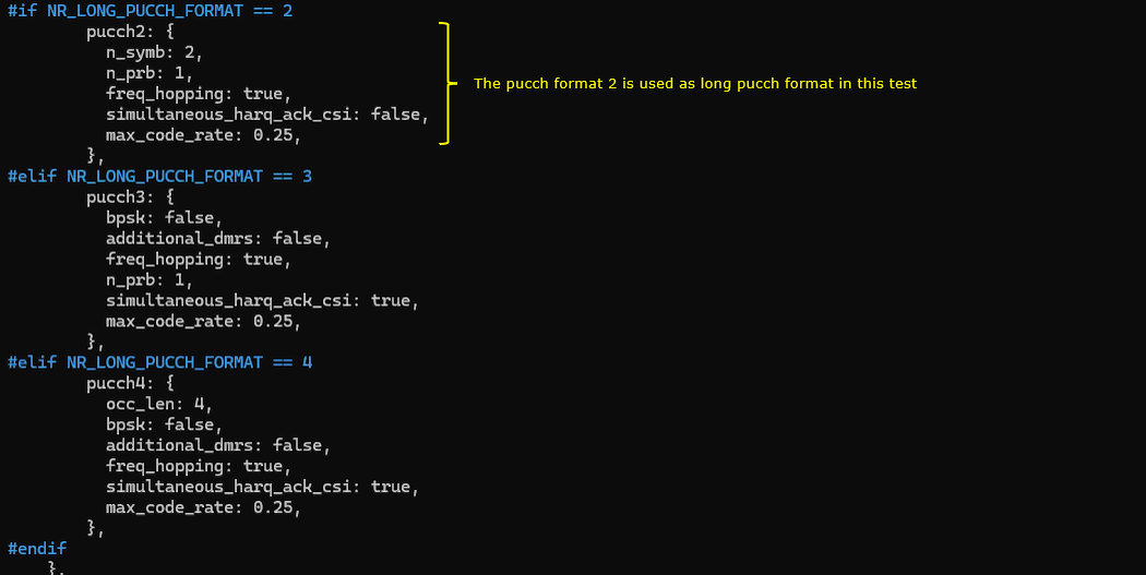
Perform the Test
Check cell configurations with cell phy and cell command to confirm that cell configuration is properly configured as you intended.

Power on UE and make it sure the attach is complete and some traffic goes on.

Log Analysis
The most important part of this tutorial is Log Anaysis and figure out how the configuration parameters are assocated with the related part of the log.
PUCCH is configured in two RRC message in Amarisoft gNB. SIB1 and RRC Setup meaning that you need to collect SIB messages as well as default logs.
To collect the SIB, I first enabled BCCH, MIB, CSI. BCCH is to collect SIB, CSI and MIB are optional for this test, but I would recommend to enable these options.
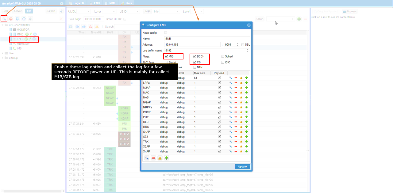
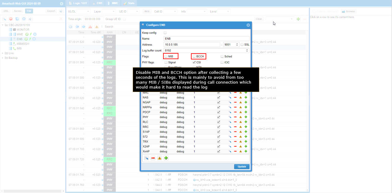
Just collect the log for a few seconds with above options and disable MIB, BCCH option to stop logging MIB, SIB. If you keep these options enabled during the entire test, you would see so many MIBs and SIBs in the middle of other signaling messages and traffics which make would make it diffuclt to analyze the log.
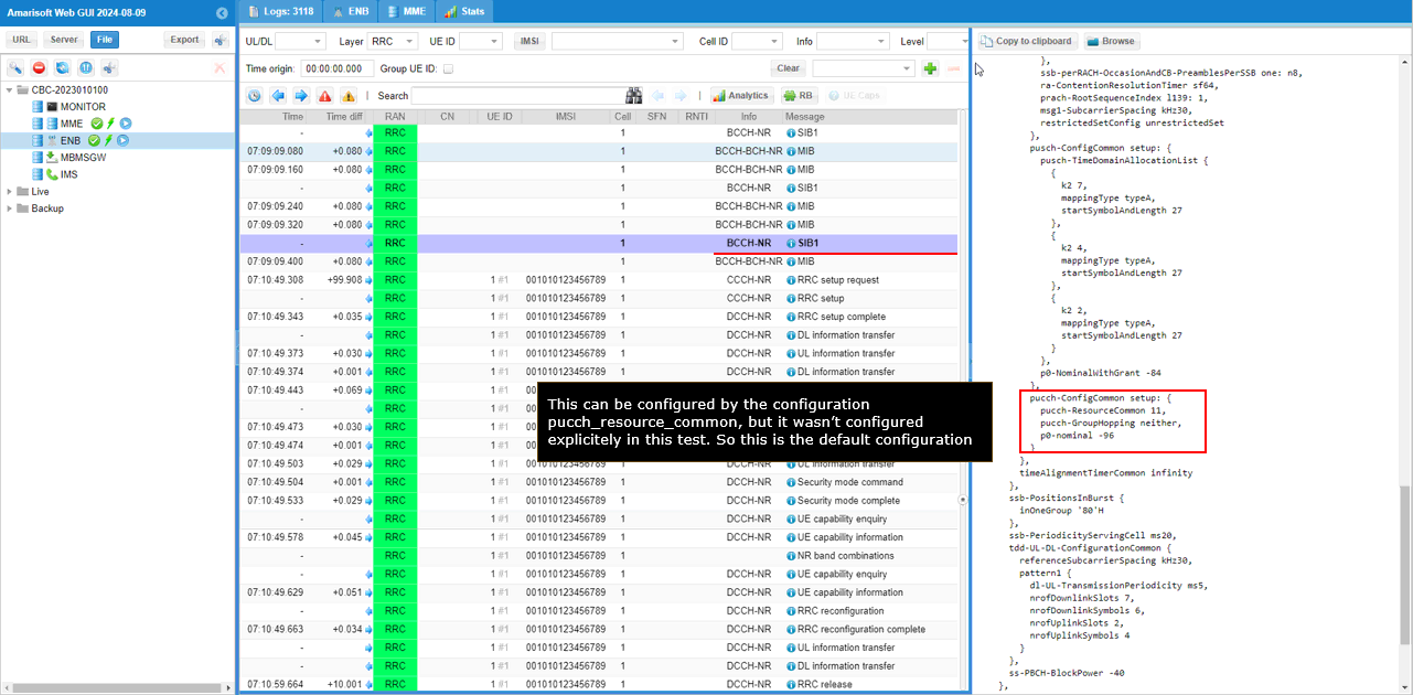
Once you collected all the log for the test, let's first check out the pucch-ConfigCommon. In this test, I didn't configure this myself, so pucch-ResourceCommon was automatically set by gNB to 11.
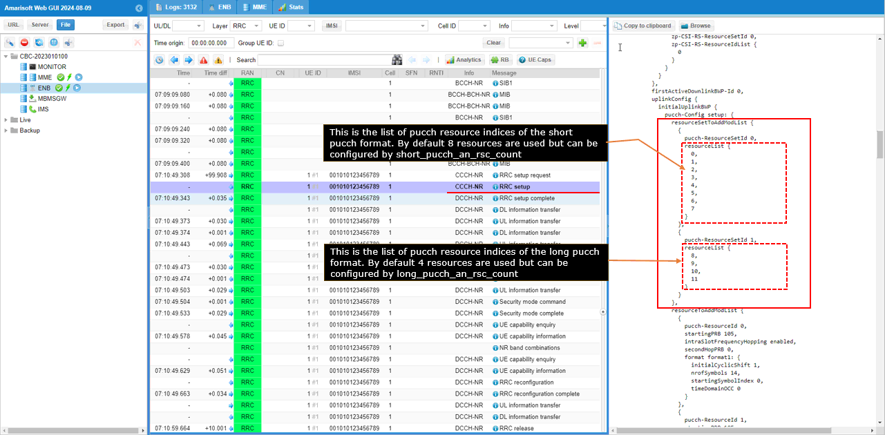
Now check out the pucch resourceSet configuration in RRC Setup. You see 8 pucch resources are assigned to the pucch-ResourceSetId 0 and 4 pucch resources are assigned to the pucch-ResourceSetId 1. This is default setup. You can modify the number of elements in each of the resource set by short_pucch_an_rsc_count and long_pucch_an_rsc_count if you want.
Each of the elements are associated each physical resources of pucch. (
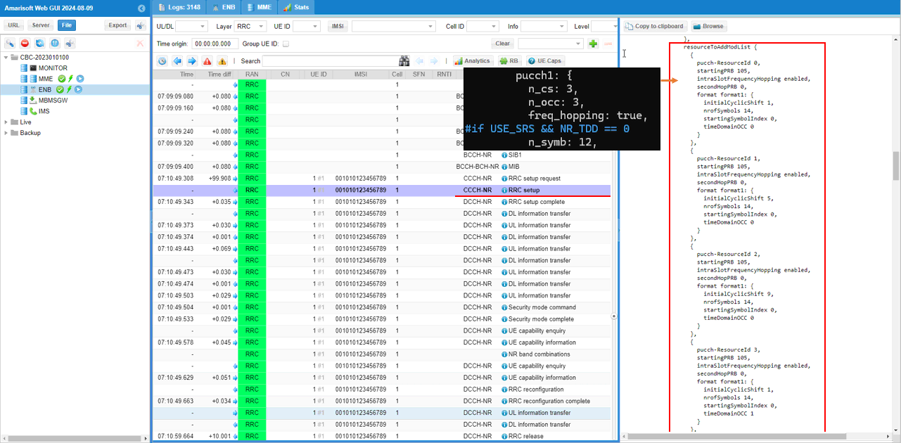
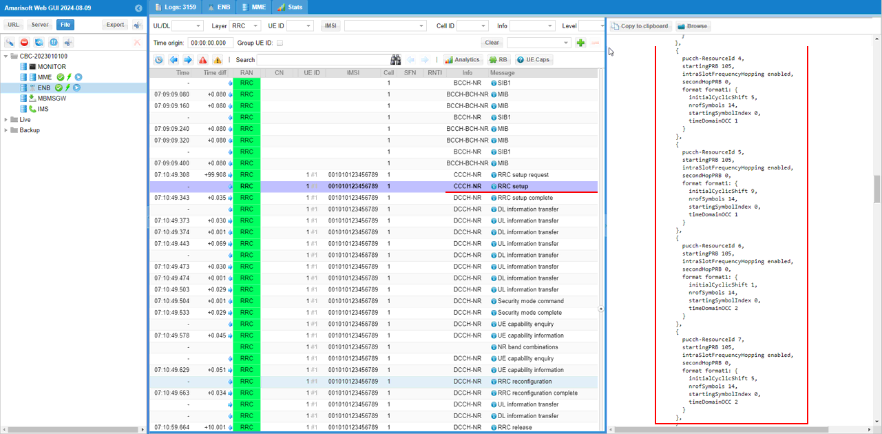
Now check out each pucch resource setting in RRC Setup. You would see a lot of resources are created automatically. In general, the total number of resources created here would be (the number of elements in the first pucchResourceSet + the number of elements in the second pucchResourceSet + 1 + 1). In this test, you would see 14 configuration in total (8+4+1+1). '1+1' indicates on pucch resources for SR and one pucch resources for CSI report.
In case of pucch format 1 used in this test, only freq_hopping is directly mapped to the RRC message. n_cs, n_occ does not have direct correspondance to RRC message. It impacts indirectly on the RRC configuration. High level descriptions on the parameters set in this configuration is as follows :
- n_cs : this is related to initialCyclicShift in RRC, but this does not indicates the value of initialCyclicShift but the number of different initialCyclicShift values that will be configured in RRC
- n_cs: 2 => two different initialCyclicShift values with interval of 6 within the range of [0,11]. For example, it may use 1 and 7 as initialCyclicShift values
- n_cs: 3 => three different initialCyclicShift values with interval of 4 within the range of [0,11]. For example, it may use 1,5 and 9 as initialCyclicShift values
- n_cs: 4 => four different initialCyclicShift values with interval of 3 within the range of [0,11]. For example, it may use 1,4,7 and 10 as initialCyclicShift values
- n_occ : this is related to timeDomainOCC. n_occ value indicates the integer in range of 0~(n_occ-1) will be used as timeDomainOCC in RRC
- freq_hopping : determine whether freq_hopping is applied or not. It is simple.
- n_symb : determined the number of consecutive OFDM symbols for the pucch format 1. default value is 14. Since this test case is for NR_TDD = 1 and USE_SRS = 0, n_symb:12 part is not applied and the default value (14) will be used.
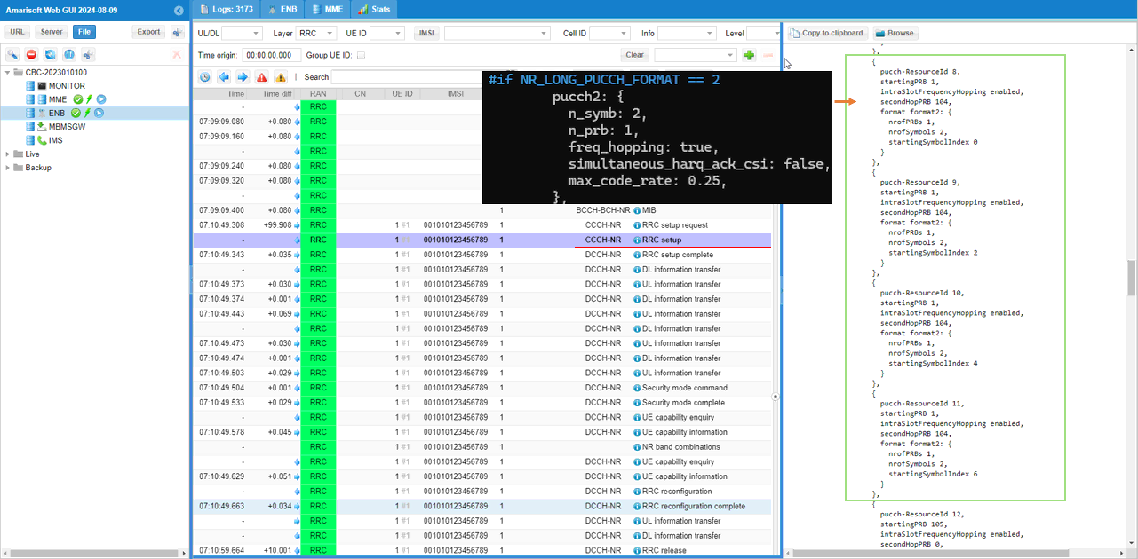
Now you can check out the 4 pucch format 2 which are mapped to the second pucch resource set. The 4 resources are created by the following configuration. The only differences among each resources is startingSymbolIndex which is automatically configured by gNB.
Lastly you see two additional pucch resources, one pucch format 1 for SR reception and another one pucch format 2 for CSI report reception.
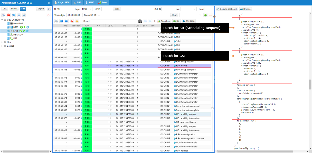
Now we have gone through all the pucch configuration and you should be ready to apply all the RRC configurations to the analysis of each PUCCH in PHY log. But it is not easy to remember the entire RRC message or cumbersome to look into RRC message over and over. So my trick is to create a lookup table as follows so that you can easily find which configuration is used for a specific PUCCH based on the log.
|
Config |
Format |
pucch-ResourceId |
startingPRB |
startingSymbolIndex |
nrofSymbols |
initialCyclicShift |
timeDomainOCC |
Hopping |
|
(A) |
1 |
|
0 |
0 |
14 |
0 |
0 |
neither |
|
(B) |
1 |
0 |
105 |
0 |
14 |
1 |
0 |
enabled |
|
(C) |
1 |
1 |
105 |
0 |
14 |
5 |
0 |
enabled |
|
(D) |
1 |
2 |
105 |
0 |
14 |
9 |
0 |
enabled |
|
(E) |
1 |
3 |
105 |
0 |
14 |
1 |
1 |
enabled |
|
(F) |
1 |
4 |
105 |
0 |
14 |
5 |
1 |
enabled |
|
(G) |
1 |
5 |
105 |
0 |
14 |
9 |
1 |
enabled |
|
(H) |
1 |
6 |
105 |
0 |
14 |
1 |
2 |
enabled |
|
(I) |
1 |
7 |
105 |
0 |
14 |
5 |
2 |
enabled |
|
(J) |
2 |
8 |
1 |
0 |
2 |
N/A |
N/A |
enabled |
|
(K) |
2 |
9 |
1 |
2 |
2 |
N/A |
N/A |
enabled |
|
(L) |
2 |
10 |
1 |
4 |
2 |
N/A |
N/A |
enabled |
|
(M) |
2 |
11 |
1 |
6 |
2 |
N/A |
N/A |
enabled |
|
(N) |
1 |
12 |
105 |
0 |
14 |
9 |
2 |
enabled |
|
(O) |
2 |
13 |
1 |
8 |
2 |
N/A |
N/A |
enabled |
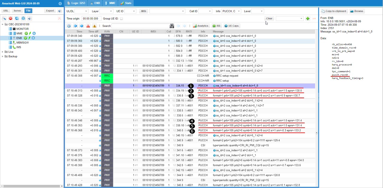
Now let's have some practice to apply the lookup table to a log analysis. Take following log sniffet as an example,
In case of PUCCH for ack/nack, which pucch resource should be used is explicitely defined by pucch_rsc in DCI as shown in (1). But pucch for SR or CSI is not explicitely specified by DCI and you need to figure it out the PUCCH log information and the lookup table we created above. What you have to do is to create a mapping table between the log information and Config as shown below.
|
Log |
Format |
startingPRB |
startingSymbolIndex |
nrofSymbols |
initialCyclicShift |
timeDomainOCC |
Hopping |
|
Config |
|
(2) |
1 |
0 |
0 |
14 |
0 |
0 |
neither |
==> |
(A) |
|
(3) |
1 |
105 |
0 |
14 |
9 |
2 |
enabled |
==> |
(N) |
|
(4) |
1 |
105 |
0 |
14 |
1 |
0 |
enabled |
==> |
(B) |
|
(5) |
1 |
105 |
0 |
14 |
1 |
0 |
enabled |
==> |
(B) |
|
(6) |
1 |
105 |
0 |
14 |
9 |
2 |
enabled |
==> |
(N) |
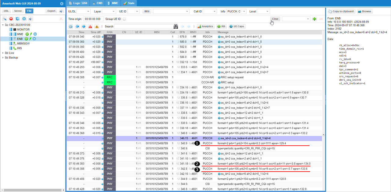
Now let's take another example as shown below.
What you have to do is to create a mapping table between the log information and Config as shown below.
|
Log |
Format |
startingPRB |
startingSymbolIndex |
nrofSymbols |
initialCyclicShift |
timeDomainOCC |
Hopping |
|
Config |
|
(1) |
2 |
1 |
8 |
2 |
N/A |
N/A |
enabled |
==> |
(O) |
|
(2) |
1 |
105 |
0 |
14 |
1 |
0 |
enabled |
==> |
(B) |
|
(3) |
1 |
105 |
0 |
14 |
9 |
2 |
enabled |
==> |
(N) |
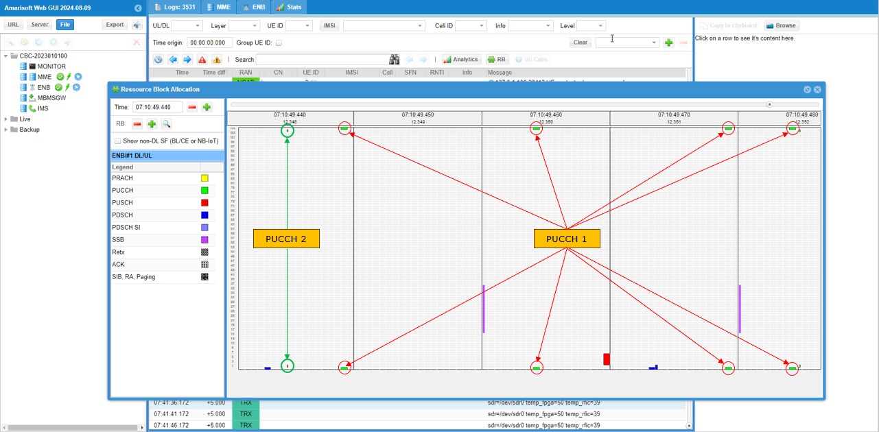
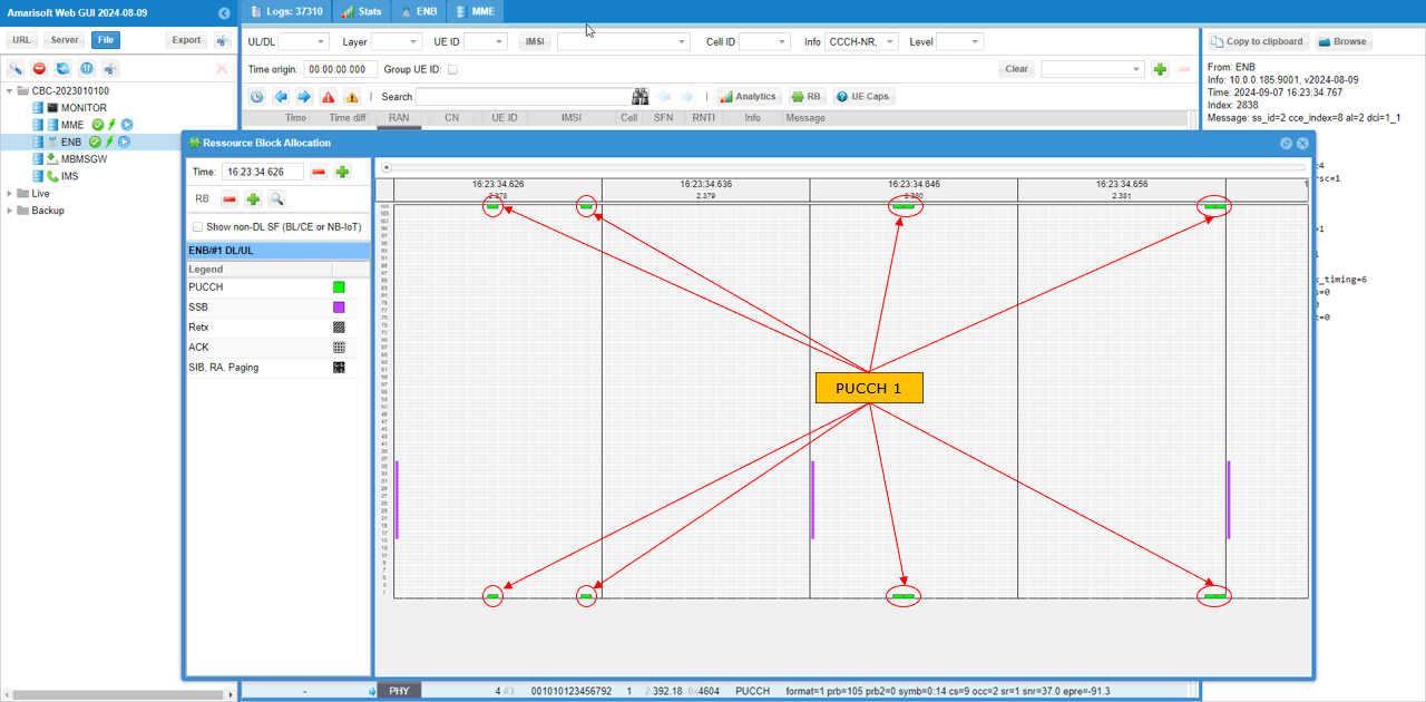
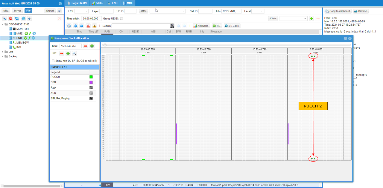
If you plot an RB map, you can get some visual mapping for the pucch resources. (
Sub Test 1 : Default Configuration - Multiple UE
In this subtest, I will use the exactly same configuration as in previous test in terms of pucch configuration. The difference is the number of UEs connected to gNB. I just modified the configuration just a little bit to support multiple UE and get 5 UEs connected to gNB. (
The main reason for getting multiple UE connected is to let gNB to use diverse pucch resources in DCI 1_x. As you might have noticed in previous test log, when there is not much demand for PUCCH (mostly by single UE and low traffic) gNB tend to use always the same pucch resources (mostly the first pucch resources) since they are always available. What I wanted to do in this test is to increase the demand of pucch so that gNB would have chance to use some other pucch resources than stick to the first resources always.
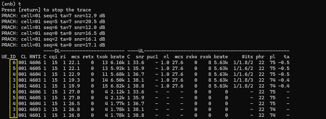
Running the test, I got 5 different UEs (UE ID,1,3,4,5,6) connected as shown below. I just got them to complete the initial attach without injecting any user traffic. (
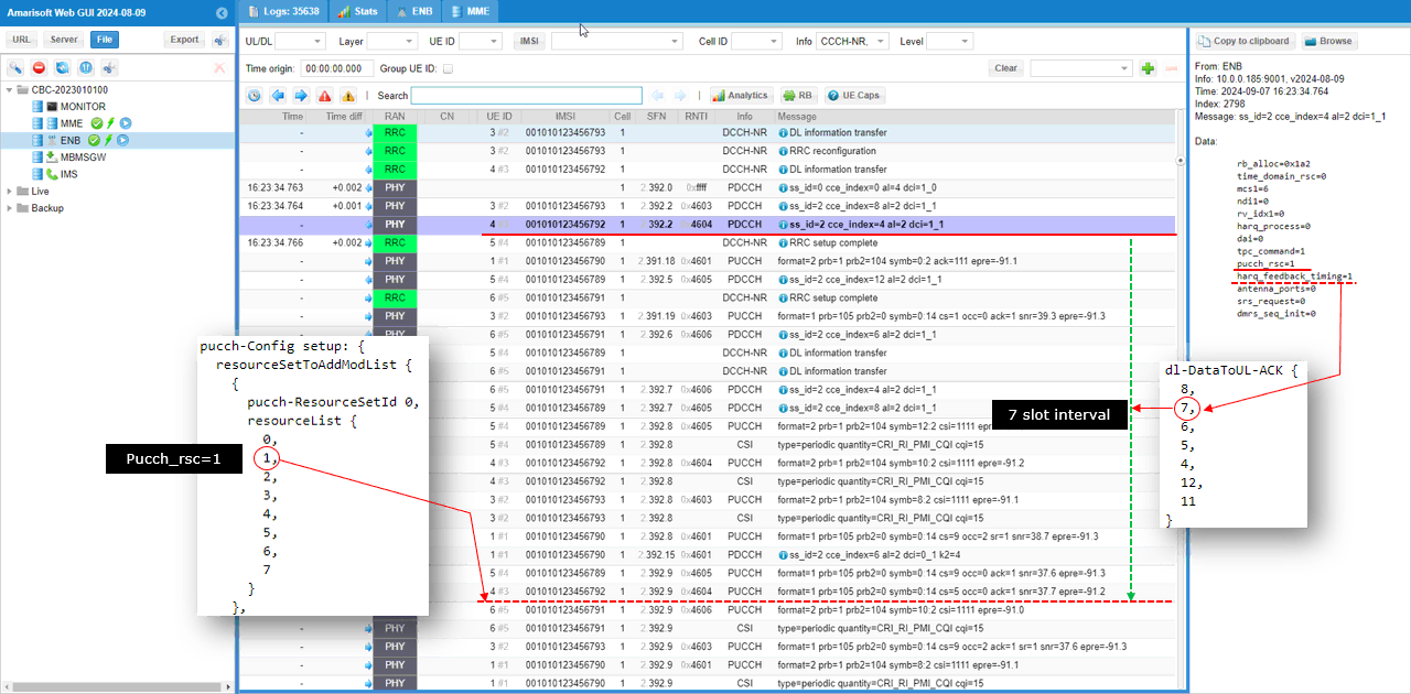
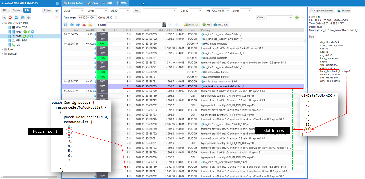
In log analysis in previous test, I identified a specific pucch resources mostly based on the contents of pucch log print and the lookup table that I created, but in this test I will identify the specific pucch resources based on DCI (pucch_rsc, harq_freeback_timing) and some IEs in RRC message.
In the first example shown below,
- pucch_rsc in DCI is 1
- harq_feedback_timing in DCI is 1 which maps to the index 1 of dl-DataToUL-ACK that is 7.
- Find pucch resource id in the first pucch-ResourceSet pointed by pucch_rsc (the index 1 = the second elements in this case) which is mapped to pucch resource 1
- Go to the subfram / slot that is pointed by the DCI slot number + dl-DataToUL-ACK and find the pucch that corresponds to the physical resource of pucch-resource id 1 (You would need the lookup table created in previous test)
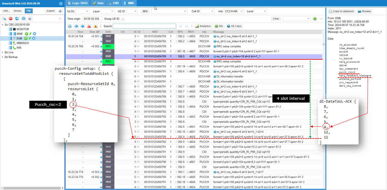
Applying the same logic to following DCI
- pucch_rsc in DCI is 2
- harq_feedback_timing in DCI is 4 which maps to the index 1 of dl-DataToUL-ACK that is 4.
- Find pucch resource id in the first pucch-ResourceSet pointed by pucch_rsc (the index 2 = the third element in this case) which is mapped to pucch resource 2
- Go to the subfram / slot that is pointed by the DCI slot number + dl-DataToUL-ACK and find the pucch that corresponds to the physical resource of pucch-resource id 2 (You would need the lookup table created in previous test)
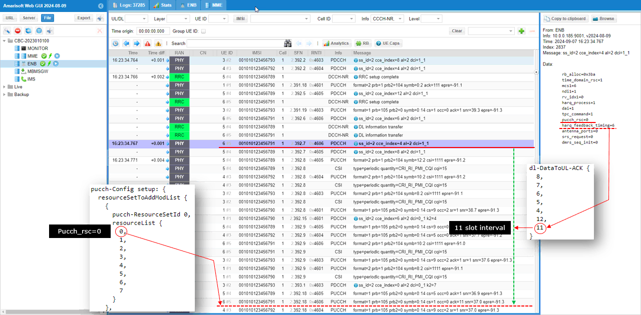
Applying the same logic
- pucch_rsc in DCI is 0
- harq_feedback_timing in DCI is 6 which maps to the index 6of dl-DataToUL-ACK that is 11.
- Find pucch resource id in the first pucch-ResourceSet pointed by pucch_rsc (the index 0 = the third element in this case) which is mapped to pucch resource 0
- Go to the subfram / slot that is pointed by the DCI slot number + dl-DataToUL-ACK and find the pucch that corresponds to the physical resource of pucch-resource id 0 (You would need the lookup table created in previous test)
Last example
- pucch_rsc in DCI is 1
- harq_feedback_timing in DCI is 6 which maps to the index 6of dl-DataToUL-ACK that is 11.
- Find pucch resource id in the first pucch-ResourceSet pointed by pucch_rsc (the index 1 = the third element in this case) which is mapped to pucch resource 1
- Go to the subfram / slot that is pointed by the DCI slot number + dl-DataToUL-ACK and find the pucch that corresponds to the physical resource of pucch-resource id 1 (You would need the lookup table created in previous test)
If you plot an RB map, you can get some visual mapping for the pucch resources. (
RRC / NAS Signaling
SIB1 (SA)
: This is the SIB1 message sent by gNB to configure NR SA. (
{
message c1: systemInformationBlockType1: {
cellSelectionInfo {
q-RxLevMin -70,
q-QualMin -20
},
cellAccessRelatedInfo {
plmn-IdentityInfoList {
{
plmn-IdentityList {
{
mcc {
0,
0,
1
},
mnc {
0,
1
}
}
},
trackingAreaCode '000064'H,
cellIdentity '001234501'H,
cellReservedForOperatorUse notReserved
}
}
},
servingCellConfigCommon {
downlinkConfigCommon {
frequencyInfoDL {
frequencyBandList {
{
freqBandIndicatorNR 78
}
},
offsetToPointA 30,
scs-SpecificCarrierList {
{
offsetToCarrier 0,
subcarrierSpacing kHz30,
carrierBandwidth 106
}
}
},
initialDownlinkBWP {
genericParameters {
locationAndBandwidth 28875,
subcarrierSpacing kHz30
},
pdcch-ConfigCommon setup: {
commonControlResourceSet {
controlResourceSetId 1,
frequencyDomainResources '011111110000000000000000000000000000000000000'B,
duration 2,
cce-REG-MappingType nonInterleaved: NULL,
precoderGranularity sameAsREG-bundle
},
commonSearchSpaceList {
{
searchSpaceId 1,
controlResourceSetId 1,
monitoringSlotPeriodicityAndOffset sl1: NULL,
monitoringSymbolsWithinSlot '10000000000000'B,
nrofCandidates {
aggregationLevel1 n0,
aggregationLevel2 n0,
aggregationLevel4 n4,
aggregationLevel8 n0,
aggregationLevel16 n0
},
searchSpaceType common: {
dci-Format0-0-AndFormat1-0 {
}
}
}
},
searchSpaceSIB1 0,
searchSpaceOtherSystemInformation 1,
pagingSearchSpace 1,
ra-SearchSpace 1
},
pdsch-ConfigCommon setup: {
pdsch-TimeDomainAllocationList {
{
mappingType typeA,
startSymbolAndLength 53
},
{
mappingType typeA,
startSymbolAndLength 44
}
}
}
},
bcch-Config {
modificationPeriodCoeff n4
},
pcch-Config {
defaultPagingCycle rf128,
nAndPagingFrameOffset oneT: NULL,
ns one
}
},
uplinkConfigCommon {
frequencyInfoUL {
scs-SpecificCarrierList {
{
offsetToCarrier 0,
subcarrierSpacing kHz30,
carrierBandwidth 106
}
}
},
initialUplinkBWP {
genericParameters {
locationAndBandwidth 28875,
subcarrierSpacing kHz30
},
rach-ConfigCommon setup: {
rach-ConfigGeneric {
prach-ConfigurationIndex 160,
msg1-FDM one,
msg1-FrequencyStart 7,
zeroCorrelationZoneConfig 15,
preambleReceivedTargetPower -110,
preambleTransMax n7,
powerRampingStep dB4,
ra-ResponseWindow sl20
},
ssb-perRACH-OccasionAndCB-PreamblesPerSSB one: n8,
ra-ContentionResolutionTimer sf64,
prach-RootSequenceIndex l139: 1,
msg1-SubcarrierSpacing kHz30,
restrictedSetConfig unrestrictedSet
},
pusch-ConfigCommon setup: {
pusch-TimeDomainAllocationList {
{
k2 7,
mappingType typeA,
startSymbolAndLength 27
},
{
k2 4,
mappingType typeA,
startSymbolAndLength 27
},
{
k2 2,
mappingType typeA,
startSymbolAndLength 27
}
},
p0-NominalWithGrant -84
},
pucch-ConfigCommon setup: {
pucch-ResourceCommon 11,
pucch-GroupHopping neither,
p0-nominal -96
}
},
timeAlignmentTimerCommon infinity
},
ssb-PositionsInBurst {
inOneGroup '80'H
},
ssb-PeriodicityServingCell ms20,
tdd-UL-DL-ConfigurationCommon {
referenceSubcarrierSpacing kHz30,
pattern1 {
dl-UL-TransmissionPeriodicity ms5,
nrofDownlinkSlots 7,
nrofDownlinkSymbols 6,
nrofUplinkSlots 2,
nrofUplinkSymbols 4
}
},
ss-PBCH-BlockPower -40
},
ue-TimersAndConstants {
t300 ms1000,
t301 ms1000,
t310 ms1000,
n310 n1,
t311 ms30000,
n311 n1,
t319 ms1000
}
}
}
RRC Setup (SA)
: This is the RRC Setup message sent by gNB to configure NR SA. (
{
message c1: rrcSetup: {
rrc-TransactionIdentifier 0,
criticalExtensions rrcSetup: {
radioBearerConfig {
srb-ToAddModList {
{
srb-Identity 1
}
}
},
masterCellGroup {
cellGroupId 0,
rlc-BearerToAddModList {
{
logicalChannelIdentity 1,
servedRadioBearer srb-Identity: 1,
mac-LogicalChannelConfig {
ul-SpecificParameters {
priority 1,
prioritisedBitRate infinity,
bucketSizeDuration ms5,
logicalChannelGroup 0,
schedulingRequestID 0,
logicalChannelSR-Mask FALSE,
logicalChannelSR-DelayTimerApplied FALSE
}
}
}
},
mac-CellGroupConfig {
schedulingRequestConfig {
schedulingRequestToAddModList {
{
schedulingRequestId 0,
sr-TransMax n64
}
}
},
bsr-Config {
periodicBSR-Timer sf20,
retxBSR-Timer sf320
},
tag-Config {
tag-ToAddModList {
{
tag-Id 0,
timeAlignmentTimer infinity
}
}
},
phr-Config setup: {
phr-PeriodicTimer sf500,
phr-ProhibitTimer sf200,
phr-Tx-PowerFactorChange dB3,
multiplePHR FALSE,
dummy FALSE,
phr-Type2OtherCell FALSE,
phr-ModeOtherCG real
},
skipUplinkTxDynamic FALSE
},
physicalCellGroupConfig {
pdsch-HARQ-ACK-Codebook dynamic
},
spCellConfig {
spCellConfigDedicated {
initialDownlinkBWP {
pdcch-Config setup: {
controlResourceSetToAddModList {
{
controlResourceSetId 3,
frequencyDomainResources '111111110000000000000000000000000000000000000'B,
duration 1,
cce-REG-MappingType nonInterleaved: NULL,
precoderGranularity sameAsREG-bundle
},
{
controlResourceSetId 4,
frequencyDomainResources '000011110000000000000000000000000000000000000'B,
duration 1,
cce-REG-MappingType nonInterleaved: NULL,
precoderGranularity sameAsREG-bundle
}
},
searchSpacesToAddModList {
{
searchSpaceId 2,
controlResourceSetId 3,
monitoringSlotPeriodicityAndOffset sl1: NULL,
monitoringSymbolsWithinSlot '10000000000000'B,
nrofCandidates {
aggregationLevel1 n0,
aggregationLevel2 n4,
aggregationLevel4 n2,
aggregationLevel8 n1,
aggregationLevel16 n0
},
searchSpaceType ue-Specific: {
dci-Formats formats0-1-And-1-1
}
},
{
searchSpaceId 3,
controlResourceSetId 4,
monitoringSlotPeriodicityAndOffset sl1: NULL,
monitoringSymbolsWithinSlot '10000000000000'B,
nrofCandidates {
aggregationLevel1 n0,
aggregationLevel2 n4,
aggregationLevel4 n2,
aggregationLevel8 n1,
aggregationLevel16 n0
},
searchSpaceType ue-Specific: {
dci-Formats formats0-1-And-1-1
}
}
}
},
pdsch-Config setup: {
dmrs-DownlinkForPDSCH-MappingTypeA setup: {
dmrs-AdditionalPosition pos1
},
tci-StatesToAddModList {
{
tci-StateId 0,
qcl-Type1 {
referenceSignal ssb: 0,
qcl-Type typeD
}
}
},
resourceAllocation resourceAllocationType1,
rbg-Size config1,
prb-BundlingType staticBundling: {
bundleSize wideband
},
zp-CSI-RS-ResourceToAddModList {
{
zp-CSI-RS-ResourceId 0,
resourceMapping {
frequencyDomainAllocation row4: '100'B,
nrofPorts p4,
firstOFDMSymbolInTimeDomain 4,
cdm-Type fd-CDM2,
density one: NULL,
freqBand {
startingRB 0,
nrofRBs 108
}
},
periodicityAndOffset slots80: 1
}
},
p-ZP-CSI-RS-ResourceSet setup: {
zp-CSI-RS-ResourceSetId 0,
zp-CSI-RS-ResourceIdList {
0
}
}
}
},
firstActiveDownlinkBWP-Id 0,
uplinkConfig {
initialUplinkBWP {
pucch-Config setup: {
resourceSetToAddModList {
{
pucch-ResourceSetId 0,
resourceList {
0,
1,
2,
3,
4,
5,
6,
7
}
},
{
pucch-ResourceSetId 1,
resourceList {
8,
9,
10,
11
}
}
},
resourceToAddModList {
{
pucch-ResourceId 0,
startingPRB 105,
intraSlotFrequencyHopping enabled,
secondHopPRB 0,
format format1: {
initialCyclicShift 1,
nrofSymbols 14,
startingSymbolIndex 0,
timeDomainOCC 0
}
},
{
pucch-ResourceId 1,
startingPRB 105,
intraSlotFrequencyHopping enabled,
secondHopPRB 0,
format format1: {
initialCyclicShift 5,
nrofSymbols 14,
startingSymbolIndex 0,
timeDomainOCC 0
}
},
{
pucch-ResourceId 2,
startingPRB 105,
intraSlotFrequencyHopping enabled,
secondHopPRB 0,
format format1: {
initialCyclicShift 9,
nrofSymbols 14,
startingSymbolIndex 0,
timeDomainOCC 0
}
},
{
pucch-ResourceId 3,
startingPRB 105,
intraSlotFrequencyHopping enabled,
secondHopPRB 0,
format format1: {
initialCyclicShift 1,
nrofSymbols 14,
startingSymbolIndex 0,
timeDomainOCC 1
}
},
{
pucch-ResourceId 4,
startingPRB 105,
intraSlotFrequencyHopping enabled,
secondHopPRB 0,
format format1: {
initialCyclicShift 5,
nrofSymbols 14,
startingSymbolIndex 0,
timeDomainOCC 1
}
},
{
pucch-ResourceId 5,
startingPRB 105,
intraSlotFrequencyHopping enabled,
secondHopPRB 0,
format format1: {
initialCyclicShift 9,
nrofSymbols 14,
startingSymbolIndex 0,
timeDomainOCC 1
}
},
{
pucch-ResourceId 6,
startingPRB 105,
intraSlotFrequencyHopping enabled,
secondHopPRB 0,
format format1: {
initialCyclicShift 1,
nrofSymbols 14,
startingSymbolIndex 0,
timeDomainOCC 2
}
},
{
pucch-ResourceId 7,
startingPRB 105,
intraSlotFrequencyHopping enabled,
secondHopPRB 0,
format format1: {
initialCyclicShift 5,
nrofSymbols 14,
startingSymbolIndex 0,
timeDomainOCC 2
}
},
{
pucch-ResourceId 8,
startingPRB 1,
intraSlotFrequencyHopping enabled,
secondHopPRB 104,
format format2: {
nrofPRBs 1,
nrofSymbols 2,
startingSymbolIndex 0
}
},
{
pucch-ResourceId 9,
startingPRB 1,
intraSlotFrequencyHopping enabled,
secondHopPRB 104,
format format2: {
nrofPRBs 1,
nrofSymbols 2,
startingSymbolIndex 2
}
},
{
pucch-ResourceId 10,
startingPRB 1,
intraSlotFrequencyHopping enabled,
secondHopPRB 104,
format format2: {
nrofPRBs 1,
nrofSymbols 2,
startingSymbolIndex 4
}
},
{
pucch-ResourceId 11,
startingPRB 1,
intraSlotFrequencyHopping enabled,
secondHopPRB 104,
format format2: {
nrofPRBs 1,
nrofSymbols 2,
startingSymbolIndex 6
}
},
{
pucch-ResourceId 12,
startingPRB 105,
intraSlotFrequencyHopping enabled,
secondHopPRB 0,
format format1: {
initialCyclicShift 9,
nrofSymbols 14,
startingSymbolIndex 0,
timeDomainOCC 2
}
},
{
pucch-ResourceId 13,
startingPRB 1,
intraSlotFrequencyHopping enabled,
secondHopPRB 104,
format format2: {
nrofPRBs 1,
nrofSymbols 2,
startingSymbolIndex 8
}
}
},
format1 setup: {
},
format2 setup: {
maxCodeRate zeroDot25
},
schedulingRequestResourceToAddModList {
{
schedulingRequestResourceId 1,
schedulingRequestID 0,
periodicityAndOffset sl40: 8,
resource 12
}
},
dl-DataToUL-ACK {
8,
7,
6,
5,
4,
12,
11
}
},
pusch-Config setup: {
txConfig codebook,
dmrs-UplinkForPUSCH-MappingTypeA setup: {
dmrs-AdditionalPosition pos1,
transformPrecodingDisabled {
}
},
pusch-PowerControl {
msg3-Alpha alpha1,
p0-AlphaSets {
{
p0-PUSCH-AlphaSetId 0,
p0 0,
alpha alpha1
}
},
pathlossReferenceRSToAddModList {
{
pusch-PathlossReferenceRS-Id 0,
referenceSignal ssb-Index: 0
}
},
sri-PUSCH-MappingToAddModList {
{
sri-PUSCH-PowerControlId 0,
sri-PUSCH-PathlossReferenceRS-Id 0,
sri-P0-PUSCH-AlphaSetId 0,
sri-PUSCH-ClosedLoopIndex i0
}
}
},
resourceAllocation resourceAllocationType1,
codebookSubset nonCoherent,
maxRank 1,
uci-OnPUSCH setup: {
betaOffsets semiStatic: {
betaOffsetACK-Index1 9,
betaOffsetACK-Index2 9,
betaOffsetACK-Index3 9,
betaOffsetCSI-Part1-Index1 7,
betaOffsetCSI-Part1-Index2 7,
betaOffsetCSI-Part2-Index1 7,
betaOffsetCSI-Part2-Index2 7
},
scaling f1
}
},
srs-Config setup: {
srs-ResourceSetToAddModList {
{
srs-ResourceSetId 0,
srs-ResourceIdList {
0
},
resourceType aperiodic: {
aperiodicSRS-ResourceTrigger 1,
slotOffset 7
},
usage codebook,
p0 -84,
pathlossReferenceRS ssb-Index: 0
}
},
srs-ResourceToAddModList {
{
srs-ResourceId 0,
nrofSRS-Ports port1,
transmissionComb n2: {
combOffset-n2 0,
cyclicShift-n2 0
},
resourceMapping {
startPosition 0,
nrofSymbols n1,
repetitionFactor n1
},
freqDomainPosition 0,
freqDomainShift 9,
freqHopping {
c-SRS 22,
b-SRS 3,
b-hop 0
},
groupOrSequenceHopping neither,
resourceType aperiodic: {
},
sequenceId 500
}
}
}
},
firstActiveUplinkBWP-Id 0,
pusch-ServingCellConfig setup: {
}
},
pdcch-ServingCellConfig setup: {
},
pdsch-ServingCellConfig setup: {
nrofHARQ-ProcessesForPDSCH n16
},
csi-MeasConfig setup: {
nzp-CSI-RS-ResourceToAddModList {
{
nzp-CSI-RS-ResourceId 0,
resourceMapping {
frequencyDomainAllocation row2: '100'H,
nrofPorts p1,
firstOFDMSymbolInTimeDomain 3,
cdm-Type noCDM,
density one: NULL,
freqBand {
startingRB 0,
nrofRBs 108
}
},
powerControlOffset 0,
scramblingID 500,
periodicityAndOffset slots80: 1,
qcl-InfoPeriodicCSI-RS 0
},
{
nzp-CSI-RS-ResourceId 1,
resourceMapping {
frequencyDomainAllocation row1: '4'H,
nrofPorts p1,
firstOFDMSymbolInTimeDomain 5,
cdm-Type noCDM,
density three: NULL,
freqBand {
startingRB 0,
nrofRBs 108
}
},
powerControlOffset 0,
scramblingID 500,
periodicityAndOffset slots80: 1,
qcl-InfoPeriodicCSI-RS 0
},
{
nzp-CSI-RS-ResourceId 2,
resourceMapping {
frequencyDomainAllocation row1: '4'H,
nrofPorts p1,
firstOFDMSymbolInTimeDomain 9,
cdm-Type noCDM,
density three: NULL,
freqBand {
startingRB 0,
nrofRBs 108
}
},
powerControlOffset 0,
scramblingID 500,
periodicityAndOffset slots80: 1,
qcl-InfoPeriodicCSI-RS 0
},
{
nzp-CSI-RS-ResourceId 3,
resourceMapping {
frequencyDomainAllocation row1: '4'H,
nrofPorts p1,
firstOFDMSymbolInTimeDomain 5,
cdm-Type noCDM,
density three: NULL,
freqBand {
startingRB 0,
nrofRBs 108
}
},
powerControlOffset 0,
scramblingID 500,
periodicityAndOffset slots80: 2,
qcl-InfoPeriodicCSI-RS 0
},
{
nzp-CSI-RS-ResourceId 4,
resourceMapping {
frequencyDomainAllocation row1: '4'H,
nrofPorts p1,
firstOFDMSymbolInTimeDomain 9,
cdm-Type noCDM,
density three: NULL,
freqBand {
startingRB 0,
nrofRBs 108
}
},
powerControlOffset 0,
scramblingID 500,
periodicityAndOffset slots80: 2,
qcl-InfoPeriodicCSI-RS 0
}
},
nzp-CSI-RS-ResourceSetToAddModList {
{
nzp-CSI-ResourceSetId 0,
nzp-CSI-RS-Resources {
0
}
},
{
nzp-CSI-ResourceSetId 1,
nzp-CSI-RS-Resources {
1,
2,
3,
4
},
trs-Info true
}
},
csi-IM-ResourceToAddModList {
{
csi-IM-ResourceId 0,
csi-IM-ResourceElementPattern pattern1: {
subcarrierLocation-p1 s8,
symbolLocation-p1 4
},
freqBand {
startingRB 0,
nrofRBs 108
},
periodicityAndOffset slots80: 1
}
},
csi-IM-ResourceSetToAddModList {
{
csi-IM-ResourceSetId 0,
csi-IM-Resources {
0
}
}
},
csi-ResourceConfigToAddModList {
{
csi-ResourceConfigId 0,
csi-RS-ResourceSetList nzp-CSI-RS-SSB: {
nzp-CSI-RS-ResourceSetList {
0
}
},
bwp-Id 0,
resourceType periodic
},
{
csi-ResourceConfigId 1,
csi-RS-ResourceSetList csi-IM-ResourceSetList: {
0
},
bwp-Id 0,
resourceType periodic
},
{
csi-ResourceConfigId 2,
csi-RS-ResourceSetList nzp-CSI-RS-SSB: {
nzp-CSI-RS-ResourceSetList {
1
}
},
bwp-Id 0,
resourceType periodic
}
},
csi-ReportConfigToAddModList {
{
reportConfigId 0,
resourcesForChannelMeasurement 0,
csi-IM-ResourcesForInterference 1,
reportConfigType periodic: {
reportSlotConfig slots80: 9,
pucch-CSI-ResourceList {
{
uplinkBandwidthPartId 0,
pucch-Resource 13
}
}
},
reportQuantity cri-RI-PMI-CQI: NULL,
reportFreqConfiguration {
cqi-FormatIndicator widebandCQI,
pmi-FormatIndicator widebandPMI
},
timeRestrictionForChannelMeasurements notConfigured,
timeRestrictionForInterferenceMeasurements notConfigured,
groupBasedBeamReporting disabled: {
},
cqi-Table table2,
subbandSize value1
}
}
},
tag-Id 0
}
}
}
}
}
}