
NR SA NTN (Non Terrestrial Network) - UEsim
This tutorial is to show you how to configure and test NR NTN. NTN (Non Terrestrial Network) is a type of network deployment in which some type of non-terrestrial (e.g, satellite or other airborne component). Overall protocol sequence of NTN is not much different from the existing NR RAN access (LTE NB, LTE, NR), but one major difference is to handle the long propagation delay between the ground components (eNB and/or DUT) and Satellite. There are one major components introduced in 3GPP NR NTN as listed below.
- Additional SIBs : This is mainly to inform the position of Satellite (i.e, ephemeris) and default time delay. In LTE case, the SIB19 carries these information.
There are various different type of NTN deployment in 3GPP TR 38.821. Currently Amarisoft NTN implementation is as shown below.
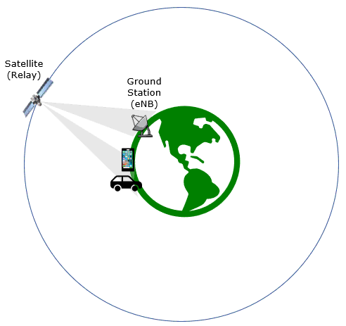
Table of Contents
- NR SA NTN (Non Terrestrial Network) - UEsim
- Introduction
- Summary of the Tutorial
- Test Setup
- Key Configuration Parameters
- Before You Start : Time Synchronization
- Before You Start : Understanding Coordinate System and Reference Point
- Architecture Overview
- Parameter Definitions & System Topology
- Position Evolution and Coordinate Mapping
- Orientation of the Local Cartesian Frame, ENU
- Configuration Reference Guide_ConfigGuide
- Example Configuration Snippet
- Test 1 : NTN with Simulated LEO and UEsim
- RRC / NAS Signaling
- FAQ
Introduction
Non-Terrestrial Networks (NTN) represent a significant advancement within the 3GPP New Radio (NR) ecosystem, enabling cellular connectivity through non-terrestrial platforms such as satellites and high-altitude platforms. Unlike traditional terrestrial networks, NR NTN introduces new architectural elements and protocol adaptations to accommodate the unique challenges posed by long-distance communication links, especially the increased propagation delay between ground-based components (such as gNodeBs or Devices Under Test) and the non-terrestrial node (e.g., satellite). NR NTN leverages established NR Radio Access Network (RAN) procedures while augmenting them with additional signaling and system information to support accurate positioning, synchronization, and delay compensation. One critical enhancement is the introduction of additional System Information Blocks (SIBs), which communicate essential satellite-specific parameters such as ephemeris data and default time delays, allowing user devices to effectively adapt to the dynamic satellite environment. These features are standardized in 3GPP specifications, with ongoing evolution to address diverse deployment scenarios as outlined in technical reports such as 3GPP TR 38.821. The integration of NTN into the broader 5G architecture expands coverage to remote and underserved areas, enhances service resilience, and enables new use cases that rely on ubiquitous connectivity, underscoring the strategic significance of NR NTN in the global telecommunications landscape.
-
Technical Context and Architectural Overview
- NR NTN integrates satellite or airborne components into the 5G NR framework, augmenting the traditional terrestrial network architecture.
- Key challenges addressed include long propagation delays, Doppler effects, and the need for precise timing and positioning information.
- System Information Blocks (SIBs), especially those conveying satellite parameters, are essential for device synchronization and communication reliability.
- Supported deployment scenarios are detailed in 3GPP TR 38.821, with evolving implementations such as those by Amarisoft broadening practical applicability.
-
Relevance and Importance of NR NTN Configuration and Testing
- Configuring and testing NR NTN is crucial for validating end-to-end connectivity, ensuring protocol compliance, and optimizing network performance under non-terrestrial conditions.
- This knowledge is foundational for engineers and researchers working on extending 5G capabilities to global, remote, or mobility-constrained environments.
- Understanding NR NTN is pivotal for enabling new services, such as IoT in remote areas, disaster recovery communications, and seamless global mobility.
-
Learning Outcomes
- Gain hands-on experience in configuring NR NTN features according to 3GPP standards.
- Understand the unique protocol adaptations and architectural considerations for non-terrestrial deployments.
- Develop the ability to evaluate and troubleshoot NR NTN scenarios using practical test setups.
- Acquire insights into interpreting system information relevant to satellite-based 5G connectivity.
-
Prerequisite Knowledge and Skills
- Familiarity with 5G NR architecture and basic protocol stack concepts.
- Experience with radio network configuration and testing tools is beneficial.
- Understanding of 3GPP technical specifications, particularly regarding NR RAN and system information structures.
- Basic knowledge of satellite communication principles will enhance comprehension of NTN-specific adaptations.
-
Tutorial Scope and Alignment
- This tutorial focuses exclusively on NR-based NTN as per recent 3GPP releases and Amarisoft implementations.
- Topics such as LTE NB-based NTN are referenced but not covered in detail; relevant resources are suggested for further reading.
- The content is aligned with current industry practices and standards, emphasizing practical configuration and testing methodologies.
Summary of the Tutorial
This tutorial provides a comprehensive overview of the test procedures, configuration steps, and methodologies for performing low-layer NTN (Non-Terrestrial Networks) testing using Amarisoft eNB, Callbox, and UEsim. The focus is on simulating a satellite-relay scenario (specifically LEO) to validate end-to-end communication under controlled lab conditions.
-
Test Setup:
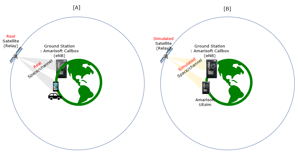
- Two test setups are described:
- Setup [A]: Satellite relay and space channel are real, while the ground station and UE use Amarisoft Callbox and a real UE.
- Setup [B]: Both satellite relay and space channel are simulated, with Amarisoft Callbox and UEsim running in a lab environment for full control and repeatability.
- The provided SIM card is used as-is. Refer to the Configuration Guide if changes are needed.
- Two test setups are described:
-
Key Configuration Parameters:
- Important parameters for both UEsim and Callbox (eNB/gNB) are listed, covering aspects such as antenna type, attenuation, feeder position, ephemeris, and channel simulation controls.
- Coordinate systems: The configuration uses both global spherical (latitude, longitude, altitude) and local Cartesian (x, y, z) frames. The ground position acts as the anchor for local offsets for cells and UEs.
- Configuration keys like
cell_groups.ground_position,cell_groups.cells.antenna.feeder_position,cell_groups.cells.position,ue_list.position, andcell_groups.cells.antenna.beam_widthare used to accurately simulate NTN geometry and radio conditions.
-
Time Synchronization (Prerequisite):
- All hosts (Callbox, UEsim, etc.) must be time-synchronized, at least via NTP, to avoid inconsistent logs and test artifacts.
-
Steps for enabling and verifying NTP (chrony) on Fedora Linux:
- Install chrony:
sudo dnf install -y chrony - Enable and start chrony:
sudo systemctl enable --now chronyd - Enable NTP via timedatectl:
sudo timedatectl set-ntp true - Optionally configure custom NTP servers in
/etc/chrony.confand restart chronyd. - Verify synchronization with
chronyc trackingandchronyc sources -v. - For immediate sync, use
sudo chronyc makestepif needed. - Troubleshooting includes checking chrony status and logs, and verifying firewall settings if required.
- Install chrony:
-
Understanding Coordinate Systems:
- The tutorial explains the hybrid use of global spherical and local ENU Cartesian systems for simulating satellite, feeder station, cell, and UE positions.
- Parameters are mapped to absolute positions to compute propagation delay, Doppler, and beam footprint accurately.
- Configuration examples illustrate how to set
ground_position,cells.position,antenna.feeder_position, andue_list.positionfor realistic geometry modeling.
-
Test 1: NTN with Simulated LEO and UEsim
-
Configuration:
- Uses modified configuration files for UEsim (
ue-demo-ntn-fr2-ue-channel.cfg) and Callbox gNB (gnb-demo-ntn-fr2-ue-channel.cfg). - NTN_FR2 is set to 1 for FR2 testing;
CHANNEL_SIMis enabled on the UEsim side to activate channel simulation, including satellite geometry, delay, and Doppler. - Key UE configuration points:
- Positioning: Both cell and UE are placed at the local reference point (
[0, 0, 0]offset). - Simple AWGN channel is used for UE-side channel model; advanced fading models are commented out.
- Positioning: Both cell and UE are placed at the local reference point (
- Key Callbox/gNB configuration points:
- LEO mode selected (
NTN_MODE=0). - Timers and MAC configuration adjusted for LEO's lower delay compared to MEO/GEO.
- Channel simulation on the gNB side is disabled in this scenario (handled by UEsim).
- SIB19 broadcasting is enabled to provide NTN assistance information (ephemeris, timing advance, etc.).
- NTN channel simulation control is configured for automatic feeder and service link simulation.
- LEO mode selected (
- Uses modified configuration files for UEsim (
-
Test Execution:
- Start LTE service on Callbox and verify configuration.
- Start LTE service on UEsim; the UE powers on automatically and begins cell search, synchronization, random access, and registration.
- If manual control is desired, comment out the
sim_eventsparameter and use the GUI or CLI to power on the UE.
-
Verification and Analysis:
-
Use the
tcommand on both UEsim and Callbox to check live radio and throughput status:- Confirm UE is connected (RNTI assigned), and both downlink and uplink traffic are active with high MCS and stable throughput.
- Check timing advance (ta), SINR, RSRP, and Doppler values to ensure they match expected NTN behavior.
-
Analyze logs to verify:
- Successful SIB1 and SIB19 decoding, confirming correct broadcast of NTN FR2 band and satellite ephemeris/timing parameters.
- Completion of RRC connection setup, security activation, UE capability exchange, and RRC reconfiguration.
- NTN statistics (satellite elevation, timing advance, Doppler) change dynamically over time, confirming realistic LEO simulation.
-
Use the
-
Configuration:
General Methodology:
- Careful configuration of both UE and gNB/Callbox to reflect the desired NTN scenario (LEO, FR2, channel simulation enabled).
- Explicit adjustment of timing, retransmission, and MAC/RRC timers to match NTN propagation characteristics.
- Verification through both real-time monitoring commands and detailed log analysis, ensuring that simulated satellite dynamics (delay, Doppler) are being exercised and reported correctly.
- Use of channel simulation is critical for non-terrestrial scenarios where Doppler and delay vary over time.
This procedure ensures a controlled, repeatable NTN test environment to validate UE and gNB behavior in the presence of simulated satellite channel effects.
Test Setup
Test setup for this tutorial is as shown below. This is just for low layer testing, you may not need any complicated IP layer setup.
- SIM Card used in this tutorial is the one delivered with the system as it is.
- If you want to change the configuration, The tutorial Configuration Guide would help
With Amarisoft eNB and UEsim, we can try with following two different setups. This figure presents two high-level test setups that can be built with Amarisoft eNB and UEsim for satellite-relay style scenarios, mainly to compare a more realistic over-the-air path with a fully simulated lab path. In setup [A], the satellite relay and space channel are treated as real, while the ground station uses an Amarisoft Callbox (eNB) and a real UE on the user side. In setup [B], the satellite relay and space channel are simulated, and both the ground station side and UE side are implemented in the lab using Amarisoft Callbox and Amarisoft UEsim. The key idea is that these two setups let you test similar end-to-end concepts at different levels of realism, cost, and controllability, from field-like validation to fully repeatable lab experimentation.
Key Configuration Parameters
Followings are important configuration parameters for this tutorial. You may click on the items for the descriptions from Amarisoft documents.
- UEsim
- type
- attenuation
- attenuation_A
- attenuation_B
- max_attenuation
- beam_width
- vertical_beam_width
- orientation
- n1
- n2
- d
- d1
- d2
- beam_width
- ephemeris_from_sib
- tle_file_name
- ephemeris
- feeder_mode
- feeder_position
- feeder_delay
- ref_signal_power
- ul_power_attenuation
- Callbox (eNB/gNB)
- ntn : In this link, you can find the descriptions for all the parameters below.
- ephemeris
- use_state_vectors
- eci_reference
- ground_position
- n_ta_common
- n_ta_drift
- n_ta_drift_var
- n_ta_common_offset
- feeder_doppler_compensation
- feeder_dl_freq
- feeder_ul_freq
- large_freq_shift
- direct_to_cell
- channel_sim_control
- type
- ue_position
- ue_doppler_shift
- ue_dl_freq
- ue_ul_freq
- feeder_doppler_shift
- ue_dl_attenuation
- ue_dl_gain_offset
- ul_sync_validity
- k_offset
- k_mac
- dynamic_k_offset
- reference_location
- t_service
- neighbour_cells
- rat_type
- t318
Before You Start : Time Synchronization
In NTN (Non-Terrestrial Networks), time synchronization across all communicating entities (satellite, gNB, UE, gateways, and sometimes multiple satellites) is fundamental, not just an implementation detail. This is because time directly maps to distance, frequency, and geometry in NTN.
There are multiple layers of technology required to achieve timing synchronization in NTN systems. These layers span from fine-grained timing, such as GNSS-disciplined clocks, PTP (IEEE 1588), and PHY-level frame alignment, to relatively coarse-grained synchronization, such as system clock alignment across hosts.
Each layer serves a different purpose. Fine-grained timing is mandatory for air-interface operation, including OFDM symbol alignment, timing advance, and Doppler compensation. Coarse-grained timing is mainly used to keep different system components operating on a consistent time reference.
In this section, I focus on one of the base minimum requirements: timing synchronization via NTP. NTP may not be sufficient for NTN PHY operation, but it is still an important prerequisite at the system level. This becomes especially important when testing NTN using Amarisoft Callbox and UE-sim. In such setups, the gNB, UE-sim, channel models, and supporting software often run on separate hosts or containers. If their system clocks are not aligned at least at the NTP level, issues such as inconsistent logs, invalid timing assumptions, and misleading test results can occur.
Enable NTP Client on Fedora Linux (Chrony)
This tutorial explains how to enable and verify NTP time synchronization (client mode) on a Fedora system using chrony, which is the default NTP implementation on Fedora. (
Prerequisites
- Fedora Linux
- User with sudo privileges
- Internet or access to an NTP server
Step 1: Install Chrony
Chrony is usually installed by default, but you can ensure it is present:
|
sudo dnf install -y chrony |
Step 2: Enable and Start the Chrony Service
Enable chrony to start at boot and start it immediately:
|
sudo systemctl enable --now chronyd |
Verify the service status:
|
systemctl status chronyd |
You should see the service running (active).
Step 3: Enable NTP via timedatectl
Fedora uses timedatectl to manage system time synchronization.
Enable NTP:
|
sudo timedatectl set-ntp true |
Verify:
|
timedatectl status |
Expected output fields:
|
System clock synchronized: yes NTP service: active |
Step 4 (Optional): Configure Custom NTP Servers
Edit the chrony configuration file:
|
sudo nano /etc/chrony.conf |
Add or modify NTP servers, for example:
|
server 0.pool.ntp.org iburst server 1.pool.ntp.org iburst server time.google.com iburst |
Save the file and restart chrony:
|
sudo systemctl restart chronyd |
Step 5: Verify Time Synchronization
Check synchronization status:
|
chronyc tracking |
View NTP sources:
|
chronyc sources -v |
A reachable source marked with ^* indicates active synchronization.
Step 6 (Optional): Force Immediate Time Sync
If the system clock is significantly incorrect:
|
sudo chronyc makestep |
Troubleshooting
Check chrony service:
|
systemctl status chronyd |
Check logs:
|
journalctl -u chronyd |
Firewall (normally not required for client mode):
|
sudo firewall-cmd --list-all |
Summary
|
sudo dnf install -y chrony sudo systemctl enable --now chronyd sudo timedatectl set-ntp true chronyc tracking |
Your Fedora system is now configured as an NTP client and will keep accurate time automatically.
Before You Start : Understanding Coordinate System and Reference Point
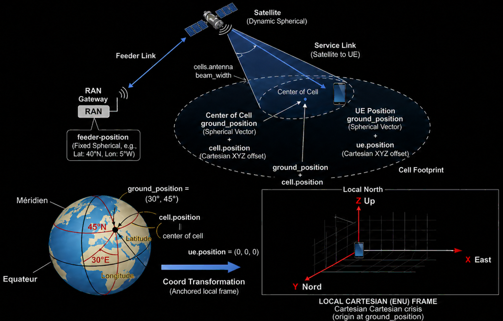
One of the first things to understand in NTN testing is that the gNB, satellite, cell center, and UE are not described by one single coordinate system. The NTN setup combines a global spherical coordinate system and a local Cartesian coordinate system. The spherical coordinate system is used to describe real geographical positions such as latitude, longitude, and altitude, while the local Cartesian coordinate system is used to describe relative offsets around a selected reference point. Because of this, it is important to clearly understand which point is used as the reference and which coordinate system is applied to each parameter.
At the high level, the RAN gateway or feeder side is described by feeder-position. This is normally a fixed geographical position and is given as a spherical coordinate such as latitude and longitude. The satellite position is dynamic and is also described in a spherical or orbital coordinate form because the satellite moves with time. The link between the RAN gateway and satellite is called the feeder link, and the link between the satellite and UE is called the service link. In the NTN simulation, both links must be represented correctly because propagation delay, Doppler, and beam coverage depend on the relative position of these nodes.
In the Amarisoft NTN channel simulator, the coordinate handling can be understood as a hybrid spherical-Cartesian method. The global positions, such as the satellite orbit, feeder gateway location, and geographical reference point, are handled in a spherical coordinate system because these objects are naturally described by latitude, longitude, altitude, or orbital position. On the other hand, the relative positions of the UE and cell center around a local reference point are handled in a Cartesian XYZ coordinate system. This separation makes the simulation easier to scale because the simulator does not need to repeatedly redefine every UE position as a full global geographical coordinate. Instead, it can track the large-scale satellite movement globally and then apply local UE or cell offsets around the selected ground reference point.
Architecture Overview
The NTN setup can be understood as a combination of two coordinate frames. The first one is the global spherical topology, which is used for objects whose positions are naturally described on the Earth or around the Earth. This includes the satellite position, satellite orbit or ephemeris information, and the fixed terrestrial gateway location used by the RAN side. These positions are usually represented by latitude, longitude, altitude, or orbital parameters, and they are important for calculating large-scale effects such as satellite movement, propagation distance, delay, and Doppler.
The second one is the local Cartesian frame, usually based on the ENU coordinate system. ENU means East, North, and Up. This local frame is anchored at a specific geodetic position on the Earth’s surface, which is normally configured as the ground_position. Once this reference point is defined, the cell center and UE position can be described as simple local XYZ offsets from that point. In this local frame, X represents the East direction, Y represents the North direction, and Z represents the Up direction.
This hybrid structure makes the NTN model easier to manage. The simulator can handle satellite motion and gateway location in the global spherical frame, while handling cell and UE placement in the local Cartesian frame. As a result, it is not necessary to manually calculate a new latitude and longitude for every small UE movement or cell offset. The global frame handles the large-scale geometry, and the local ENU frame handles the small-scale placement around the selected reference point.
Parameter Definitions & System Topology
The simulation relies on a set of core parameters to compute the absolute geometric positions used for path loss, delay, and Doppler calculations:
Global Topology Parameters
- `feeder_position` (RAN Gateway): Defined in fixed spherical/geodetic coordinates (Latitude, Longitude, Altitude). It designates the physical entry point of the Feeder Link on the Earth's surface.
- Satellite Position: Calculated dynamically by the simulator using orbital parameters broadcast via SIB19 (System Information Block 19) ephemeris data. It represents the central apex of the Service Link.
- `beam_width`: Defines the divergence angle of the satellite beam cone, outlining the geographical footprint on the surface.
Local Frame Anchor
- `ground_position`: The global geodetic anchor point defined in spherical coordinates (e.g., Latitude 45°N, Longitude 30°E). It serves as the absolute origin point `(0,0,0)` for the local Cartesian coordinate system.
Local Cartesian Offsets
Positions inside the simulation environment are represented as Cartesian 3D vectors `(x, y, z)` relative to the `ground_position`:
- `cell_groups.cells.position`: Specifies the vector offset from the `ground_position` to the physical center of a given cell footprint.
- `ue_list.position`: Specifies the vector offset from the `ground_position` to the precise position of a User Equipment instance.
Position Evolution and Coordinate Mapping
To calculate the NTN link behavior, the simulator first needs to know where each entity is located in one common absolute space. Even though the configuration may use different coordinate formats, such as spherical coordinates for the satellite or gateway and local XYZ offsets for the UE, the simulator eventually maps them into absolute position vectors. Once all nodes are represented in the same space, it can calculate the relative distance and direction between the satellite, gateway, cell center, and UE.
The basic idea is that a local position is created by adding an offset vector to a reference position. For example, ground_position defines the geodetic anchor point on the Earth, and cell.position defines the local offset from that anchor point to the center of the cell. In the same way, ue.position defines the local offset from the same or related reference point to the UE location. So the final absolute cell position can be understood as ground_position plus cell.position, and the final absolute UE position can be understood as ground_position plus ue.position.
This vector-based mapping is important because the NTN channel is not fixed. The satellite position changes over time, and the link geometry changes together with it. At every simulation time step, the simulator updates the satellite position from the orbital or ephemeris information, maps the terrestrial gateway, cell, and UE positions into the same absolute coordinate space, and then calculates the instantaneous geometry between them. From this geometry, it can derive the propagation distance, delay, Doppler shift, beam direction, and relative movement effect seen by the UE.
In simple terms, the user may configure the NTN scenario using convenient parameters such as latitude, longitude, altitude, and local XYZ offsets, but internally the simulator converts these values into a common vector representation. This allows the simulator to combine large-scale satellite motion with local UE and cell placement in a consistent way.
Orientation of the Local Cartesian Frame, ENU
The local Cartesian frame used in the NTN configuration is normally aligned with the ENU convention. ENU means East, North, and Up, and this local grid is attached to the Earth at the selected anchor point, usually the configured ground_position. The frame is tangent to the Earth surface at that anchor point, so it behaves like a small flat 3D coordinate system around the local test area.
In this local frame,
- the X-axis points toward local East,
- the Y-axis points toward local North,
- the Z-axis points upward from the Earth surface. The Up direction is not simply the global Z direction of the Earth-centered coordinate system. It is the local altitude direction at the anchor point, approximately perpendicular to the reference ellipsoid surface at that location.
This convention makes the configuration intuitive. For example, a positive X offset moves the cell or UE toward the east side of the anchor point, a positive Y offset moves it toward the north side, and a positive Z offset moves it upward in altitude. Therefore, when cell.position or ue.position is configured as a Cartesian XYZ offset, the values should be interpreted in this local ENU frame, not as global Earth-centered X/Y/Z coordinates.
Configuration Reference Guide_ConfigGuide
The NTN coordinate-related properties are configured in the gNB or UE configuration file. These parameters define how Amarisoft maps the satellite, feeder gateway, cell center, and UE into the same NTN geometry model. Some parameters use global geodetic coordinates such as latitude, longitude, and altitude, while others use local Cartesian offsets in meters.
|
JSON Key / Property |
Value Type |
Units |
Description |
|---|---|---|---|
|
|
Array |
Degrees / Meters |
Defines the reference geodetic anchor point on the Earth's surface. |
|
|
Array |
Degrees / Meters |
Defines the location of the terrestrial gateway RAN. |
|
|
Array |
Meters |
Cartesian offset vector of the cell center from the anchor point. |
|
|
Float |
Degrees |
Half-power beamwidth of the satellite antenna array payload. |
|
|
Array |
Meters |
Cartesian offset vector of the user equipment from the anchor point. |
Example Configuration Snippet
channel_sim: {
cell_groups: [
{
// Defines the reference geodetic anchor point on the Earth's surface
ground_position: {
latitude: 45.5,
longitude: 6.0
},
cells: [
{
rf_port: 0,
position: [78e3, 0, 0], // Cartesian offset vector of the cell center in Meters (78 km East)
antenna: {
type: "satellite",
ephemeris_from_sib: true,
// Defines the location of the terrestrial gateway RAN
feeder_position: {
latitude: 45.0,
longitude: 0.0
},
attenuation: "atmospheric",
gain: 80, /* satellite dish + UE VSAT, in dBi */
beam_width: 70
}
}
]
}
],
ue_list: [
{
ue_id: 1,
position: [0, 0, 0] // Cartesian offset vector of the UE from the anchor point
}
]
}
Test 1 : NTN with Simulated LEO and UEsim
This is to configure and test NTN for Simulated LEO using Amarisoft Callbox as DUT.
Configuration
The configuration shown here is common configuration for all the subtests belonging to Test 1 and I will not show this configuration repeatedly for every subtest.
I have used ue-demo-ntn-fr2-ue-channel.cfg which is copied and modified from ue-nr-ntn.cfg
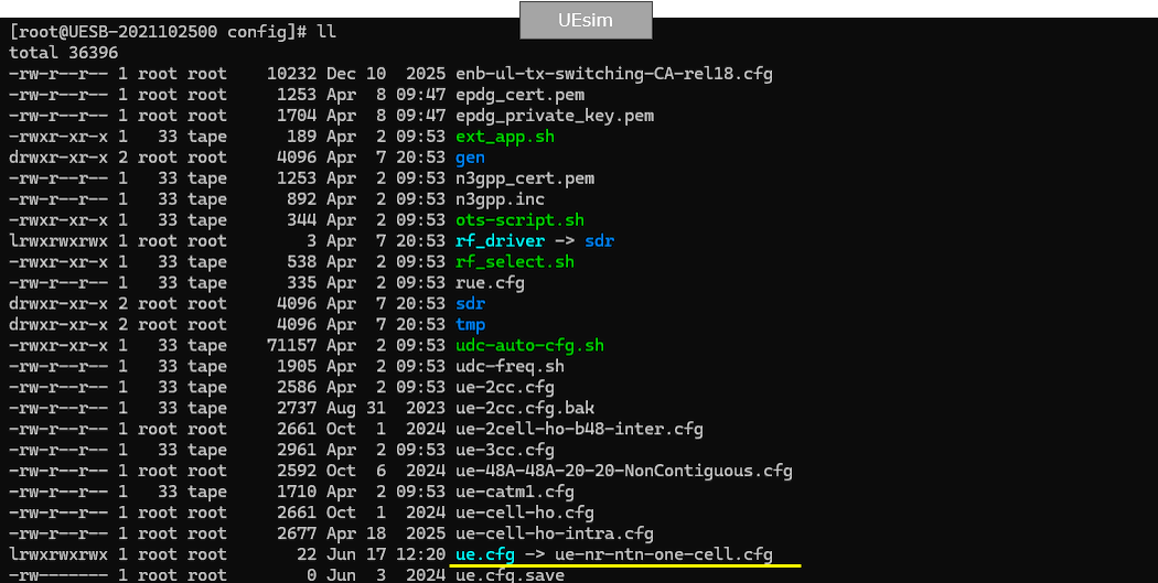
ue-demo-ntn-fr2-ue-channel.cfg is configured as shown below.
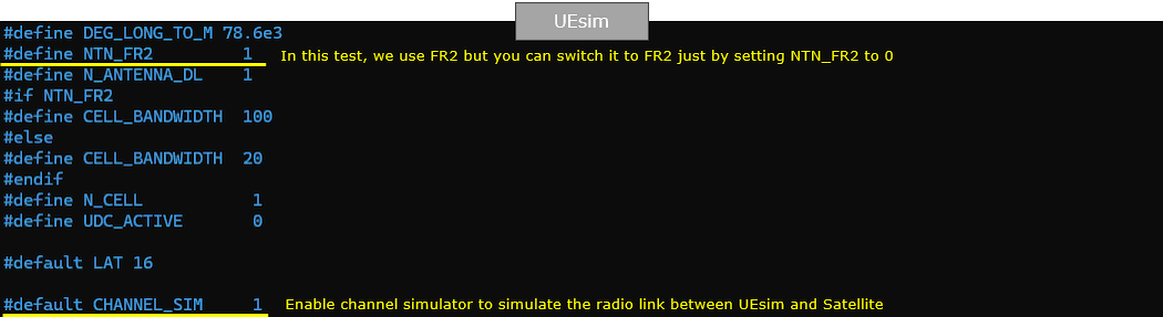
In this UEsim configuration, NTN_FR2 is set to 1, so this test uses the NTN FR2 configuration path. If you want to switch the same test to FR1, you can set NTN_FR2 to 0, and then the CELL_BANDWIDTH value follows the FR1 branch instead. With NTN_FR2 enabled, CELL_BANDWIDTH is configured as 100, while the alternative FR1 bandwidth is configured as 20. N_CELL is set to 1, meaning this test uses a single simulated cell, and UDC_ACTIVE is set to 0, so UDC is not enabled in this scenario.
The DEG_LONG_TO_M value is configured as 78.6e3. This is used as a longitude-to-meter conversion factor for the local coordinate calculation, so it helps map a longitude-related offset into an approximate distance in meters around the selected geographical reference point. LAT is set to 16 as the default latitude reference used by the configuration logic.
CHANNEL_SIM is set to 1, which is one of the most important settings in this test. This enables the Amarisoft channel simulator between UEsim and the simulated satellite/channel model. With this enabled, the UE does not simply connect through an ideal static link. Instead, the radio path can include NTN-specific effects such as satellite geometry, propagation delay, and Doppler behavior depending on the rest of the channel_sim configuration.
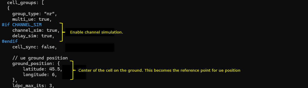
In this part, the cell_groups block defines the UE-side NR cell group and the channel simulation behavior used for the NTN test. group_type is set to "nr", so this group is used for NR operation, and multi_ue is set to true, meaning the configuration can support multiple simulated UEs under the same cell group structure.
When CHANNEL_SIM is enabled, channel_sim is set to true and delay_sim is also set to true. channel_sim enables the Amarisoft channel simulator, and delay_sim enables propagation delay simulation. This is important for NTN because the radio path is not treated as an ideal cable-like connection. Instead, the UE-side link can include NTN-specific effects such as long propagation delay caused by the satellite path.
cell_sync is set to false. By default, this parameter is true, which means Amarisoft assumes that multiple NR cells in the same cell group are synchronized at the slot level. This synchronized timing assumption is required for CA or SUL operation. However, in NTN scenarios, different cells or satellite links may have very different timing because the propagation delay can vary significantly depending on the satellite geometry and link distance. Therefore, when the cells are not expected to be slot-synchronized, cell_sync should be set to false.
ground_position defines the UE-side ground reference position. In this example, latitude is set to 45.5 and longitude is set to 6. This point becomes the geographical anchor for the local coordinate system used by the UE position. When ue.position is configured later, that UE position is interpreted as a local Cartesian offset from this ground_position. In other words, ground_position gives the absolute location on Earth, and ue.position gives the local offset from that point.
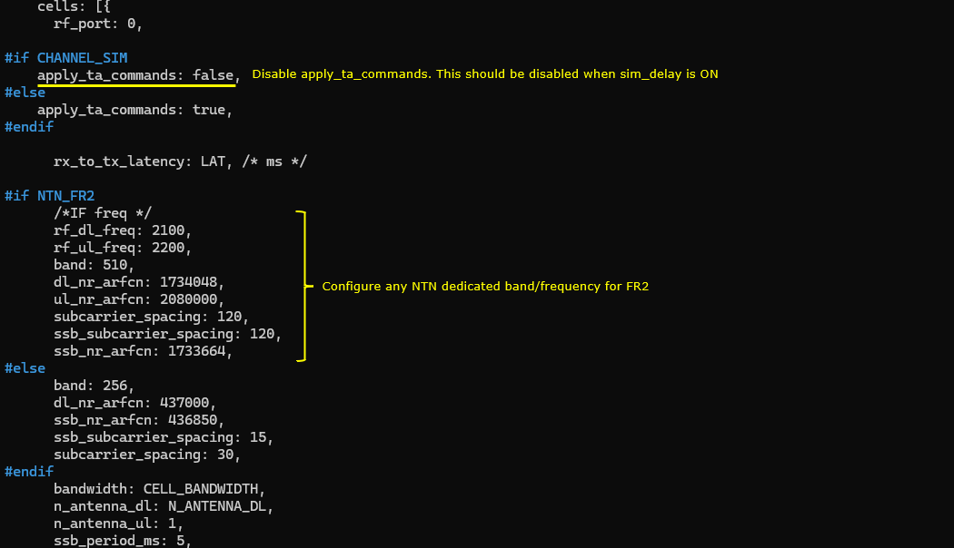
In this part, apply_ta_commands is controlled by CHANNEL_SIM. When CHANNEL_SIM is enabled, apply_ta_commands is set to false. This is the correct setting for this test because the channel simulator is already enabled with delay_sim, and Amarisoft documentation says that apply_ta_commands cannot be used together with delay_sim. apply_ta_commands is used in multi-UE mode when the UE simulator should follow timing advance commands received from the network, but when delay_sim is enabled, different UE timing advances are simulated by the channel simulator itself using delay modeling on the uplink signal. Therefore, in this NTN test, timing behavior should be handled by the simulated satellite delay model rather than by applying normal TA commands from the network. ([tech-academy.amarisoft.com][1])
rx_to_tx_latency is set to LAT. In this configuration, LAT was defined earlier as 16, so rx_to_tx_latency becomes 16 slots. According to the Amarisoft documentation, rx_to_tx_latency defines the minimum allowed latency between RX and TX and bounds the minimum k1 and k2 values allowed by the system. Increasing this value can also help performance, especially when radio frontend underflow can be a concern. For NR, Amarisoft also notes that k1, k2, and the RAR-to-PUSCH delay must satisfy the minimum latency constraint derived from rx_to_tx_latency. So in this NTN UE simulation, this value is part of the timing margin that allows the UE simulator to operate with the longer scheduling and response timing expected in a delayed NTN environment.
The next part configures the NR carrier depending on the NTN_FR2 switch. Since NTN_FR2 is enabled in this test, the FR2 branch is selected. In this branch, rf_dl_freq is set to 2100 and rf_ul_freq is set to 2200, while band is set to 510. The downlink NR-ARFCN is configured as 1734048 and the uplink NR-ARFCN is configured as 2080000. The subcarrier spacing is set to 120 kHz, and the SSB subcarrier spacing is also set to 120 kHz. The SSB NR-ARFCN is configured as 1733664. These parameters define the FR2 NTN carrier, the uplink and downlink frequency mapping, and the SSB location used by the UE simulator to search and synchronize to the simulated NTN cell.
The else branch is used only when NTN_FR2 is disabled. In that case, the configuration uses band 256 with lower NR-ARFCN values and smaller subcarrier spacing values, such as 30 kHz for the carrier and 15 kHz for SSB. Since this test is configured for NTN FR2, this branch is not active, but it remains in the file so that the same configuration can be reused for an FR1-style NTN test by changing the NTN_FR2 definition.
Finally, bandwidth is set from CELL_BANDWIDTH, n_antenna_dl is set from N_ANTENNA_DL, and n_antenna_ul is set to 1. Since NTN_FR2 was enabled earlier, CELL_BANDWIDTH follows the FR2 bandwidth setting. This completes the UE-side radio carrier configuration for the simulated LEO NTN test, while the timing-related settings above make sure that the UE simulator timing is consistent with channel-simulator-based NTN delay handling.
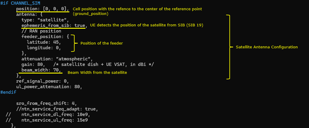
In this part of the UE-side channel simulation configuration, position is set to [0, 0, 0]. This defines the cell position as a local Cartesian offset from the reference ground position. Since all three values are zero, the cell is placed exactly at the local reference point defined by ground_position, with no East, North, or Up offset.
The antenna block defines the satellite antenna model used by the channel simulator. type is set to satellite, so this antenna is treated as a satellite antenna rather than a normal terrestrial antenna. ephemeris_from_sib is set to true, which means the UE simulator obtains the satellite ephemeris information from system information, such as SIB19, instead of relying only on a locally hardcoded satellite position. This is important for NTN because the UE needs satellite-related assistance information to estimate timing and frequency behavior correctly.
feeder_position defines the terrestrial feeder gateway position. In this example, latitude is set to 45 and longitude is set to 0. This position represents the RAN-side ground gateway used for the feeder link between the terrestrial network and the satellite. Together with the satellite position, this feeder position is used to calculate the feeder-link geometry.
attenuation is set to atmospheric, so the channel simulator includes atmospheric attenuation in the link model. gain is set to 80 dBi, which represents the combined satellite dish and UE VSAT antenna gain assumption used in this simulation. beam_width is set to 70 degrees, which defines the satellite antenna beam width. A larger beam width gives a wider coverage area, while a smaller beam width gives a narrower and more focused beam footprint.
ref_signal_power is set to 0 and ul_power_attenuation is set to 80. These values control the reference signal power and uplink attenuation behavior used by the simulated channel. In this NTN setup, they are part of the link budget configuration together with antenna gain, beam width, and atmospheric attenuation.
sro_from_freq_shift is set to 4. This parameter is used for sample rate offset handling related to frequency shift.
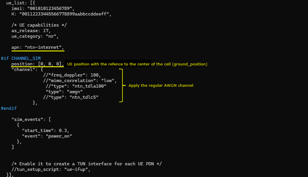
In this part, the ue_list block defines the simulated UE identity, UE capability, APN, UE position, channel model, and power-on timing. The imsi and K values identify the simulated UE and must match the subscriber information configured on the core network side. as_release is set to 17, so the UE capability is based on Release 17, which is important for NTN testing because NR NTN support is introduced in the Release 17 feature set. ue_category is set to nr, meaning this UE is configured as an NR UE, and apn is set to ntn-internet, so this APN is used when the UE establishes the data connection.
When CHANNEL_SIM is enabled, position is set to [0, 0, 0]. This position is the local Cartesian offset of the UE from the configured ground_position reference. Since all values are zero, the UE is placed exactly at the local reference point, with no East, North, or Up offset. In this test, the UE is therefore located at the center reference location used by the local NTN coordinate model.
The channel block defines the radio channel model applied to this UE. In the active configuration, the channel type is set to awgn, so the UE uses a regular additive white Gaussian noise channel. The other channel-related options, such as freq_doppler, mimo_correlation, ntn_tdla100, and ntn_tdlc5, are commented out, so they are not applied in this test. This means the scenario uses the NTN geometry and delay-related channel simulation from the surrounding configuration, but the small-scale fading model for this UE is kept simple by using AWGN.
The sim_events block controls when the UE starts operation. In this example, start_time is set to 0.3 and the event is power_on, so the simulated UE is powered on 0.3 seconds after the simulation starts. This small delay gives the cell and channel simulation enough time to initialize before the UE begins cell search, synchronization, random access, and registration. The tun_setup_script line is commented out, so the test does not automatically create a TUN interface for the UE PDN in this configuration.
Perform the Test
First run lte service on Callbox and check if the basic things are configured as intended
Then run the LTE service on the UEsim side. In this example, the UE is configured to power on automatically after the LTE service starts because the sim_events parameter is included in the UE configuration file. The configured event is power_on, so the UE starts the attach procedure automatically after the specified start_time.
If you want to control the UE manually, you can comment out the sim_events parameter in the configuration file. In that case, the LTE service will start, but the UE will remain powered off until you manually trigger UE power on from the Amarisoft Web GUI or command line. This can be useful when you want to first confirm that the UEsim service and channel simulator are running correctly before starting cell search and attach.
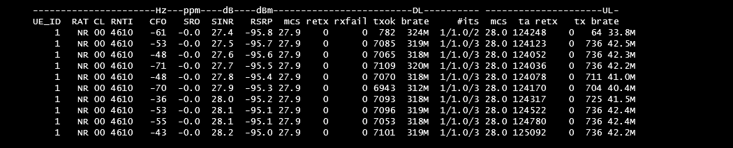
Following is the result of t command on UEsim. This command output shows the live UE radio and throughput status after the UEsim service starts and the UE is connected. The UE_ID is 1, and the RAT is NR, which confirms that the simulated UE is operating on the NR cell. The RNTI is 4610, meaning the UE has already received a C-RNTI from the gNB and is in connected mode.
The CFO and SRO columns show the frequency and sampling rate offset status. In this result, CFO changes around several tens of Hz and SRO remains close to 0.0 ppm, which indicates that the UE is maintaining frequency and sampling synchronization with the simulated NTN cell. The SINR is around 27 to 28 dB, and RSRP is around -95 dBm. These values show that the UE has a stable received signal condition in this simulated channel.
On the downlink side, mcs is around 27.9, retx is 0, and rxfail is 0. This means the downlink channel quality is good enough to use a high MCS, and there are no visible downlink retransmission or reception failure problems in this snapshot. The downlink bitrate is around 312 to 320 Mbps, which confirms that downlink traffic is being generated successfully.
On the uplink side, mcs is 28.0, txok increases continuously, retx is 0, and the uplink bitrate is around 40 to 43 Mbps. This confirms that the UE is also transmitting uplink data successfully without retransmission in this snapshot. The ta value is around 124000 to 125000 and changes slightly over time, which is expected in NTN because the timing advance follows the satellite link geometry and propagation delay behavior.
Overall, this output confirms that the UE has attached successfully and is exchanging both downlink and uplink traffic through the simulated NTN environment. The high SINR, stable RSRP, zero retransmission, increasing txok count, and active DL/UL bitrates indicate that the simulated LEO NTN link is operating normally in this test.
Log Analysis
Following is the log snapshot that are involved in communication with NTN.
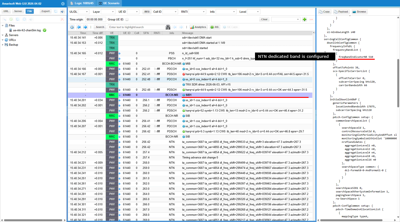
This is BCCH-NR SIB1. This message is decoded after the UE has already detected PSS, decoded PBCH, and obtained MIB. Therefore, the selected SIB1 line is an important checkpoint showing that the UE has successfully moved from physical cell detection into RRC system information decoding.
In the first snapshot, the selected SIB1 content shows freqBandIndicatorNR 510 under servingCellConfigCommon. This confirms that the cell is broadcasting the NTN FR2 dedicated band configured in the gNB configuration. Since the gNB was configured with band 510 in the NTN_FR2 branch, this decoded SIB1 proves that the configured NTN band information is actually being transmitted by the cell and successfully decoded by the UE.
The selected SIB1 also includes common cell configuration information such as frequencyInfoDL, offsetToPointA, scs-SpecificCarrierList, initialDownlinkBWP, PDCCH common configuration, and search space configuration. These parameters tell the UE how the downlink carrier is organized, where the initial bandwidth part is located, and how the UE should monitor common control channels before dedicated RRC configuration is established. This is why SIB1 is essential before random access and RRC connection establishment.
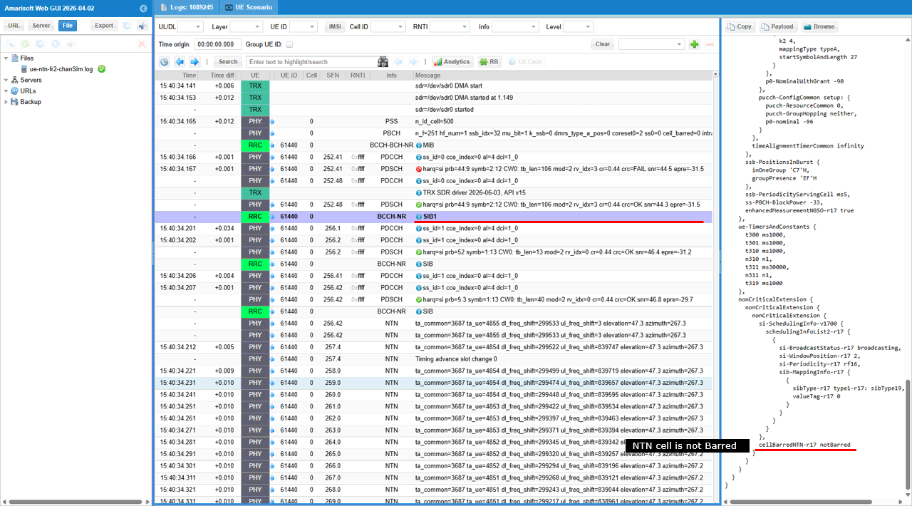
In the second snapshot, the selected SIB1 content shows additional NTN-related access information. The decoded field cellBarredNTN-r17 is set to notBarred. This is a key NTN checkpoint because it tells the UE that the NTN cell is allowed for access. If this field were barred, the UE would not be allowed to continue normal access on this NTN cell. Since it is notBarred, the UE can proceed with the NTN access procedure.
The same SIB1 also shows nonCriticalExtension and Rel-17 scheduling information, including schedulingInfoList-r17 and si-BroadcastStatus-r17 set to broadcasting. This indicates that Rel-17 system information scheduling is present and that the cell is broadcasting the related system information needed for NTN operation. This is important because NTN support is mainly introduced through Rel-17 features, and the UE needs these broadcast indications to continue acquiring the required NTN assistance information.
Overall, the selected RRC message confirms two important points. First, the UE successfully decodes SIB1 from the simulated NTN cell and verifies that the configured NTN FR2 band 510 is broadcast. Second, the NTN-specific access status shows cellBarredNTN-r17 notBarred, meaning the cell is available for NTN access. This proves that the initial RRC broadcast configuration is consistent with the intended LEO NTN FR2 test setup and that the UE can continue toward SIB acquisition, random access, and registration.
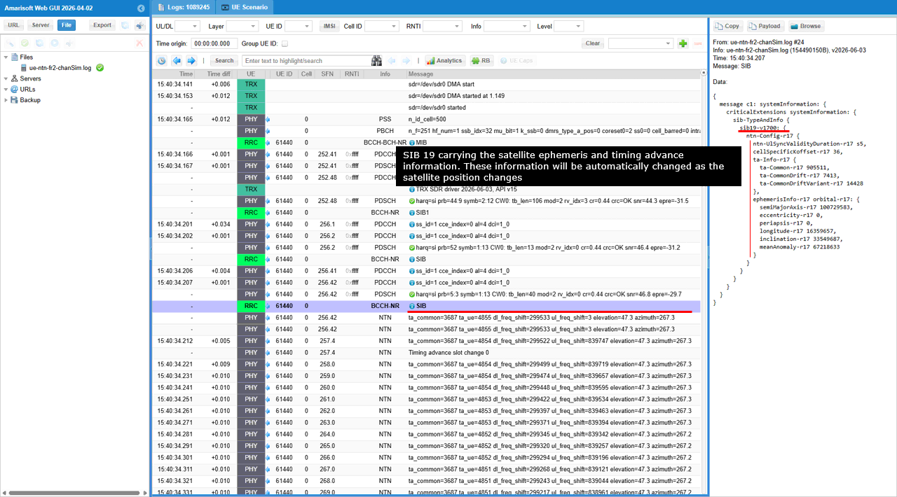
This is SIB19 message and it is an important NTN-specific system information block because it provides the UE with satellite assistance information required for NR NTN operation.
In the decoded SIB19 content, ntn-Config-r17 is present. This confirms that the cell is broadcasting Release 17 NTN configuration information. The ntn-UlSyncValidityDuration-r17 value is set to s5, which means the uplink synchronization information is valid for a limited duration. This is especially important in LEO because the satellite moves quickly, so the timing and frequency relationship between the UE and the satellite changes continuously.
The cellSpecificKoffset-r17 value is also included. This parameter provides an NTN timing offset used by the UE when handling the larger propagation delay of the satellite link. In terrestrial NR, the propagation delay is usually small enough that normal timing assumptions are sufficient, but in NTN the UE needs additional timing information so that uplink transmission can arrive at the gNB side within the expected timing window.
The ta-Info-r17 section includes ta-Common-r17, ta-CommonDrift-r17, and ta-CommonDriftVariant-r17. These values provide common timing advance information and its time variation. ta-Common-r17 represents the common timing advance component derived from the satellite geometry. ta-CommonDrift-r17 indicates how this common timing advance changes over time, and ta-CommonDriftVariant-r17 gives additional drift variation information. These parameters are necessary because the LEO satellite position changes continuously, so the propagation delay is not fixed.
The ephemerisInfo-r17 section carries the satellite orbital information. In this snapshot, the broadcast ephemeris includes parameters such as semiMajorAxis-r17, eccentricity-r17, periapsis-r17, longitude-r17, inclination-r17, and meanAnomaly-r17. These values allow the UE to understand or predict the satellite position and movement. This is why the UE simulator can derive NTN-related timing and Doppler behavior from broadcast system information rather than relying only on a fixed local assumption.
Overall, this selected SIB19 message confirms that the gNB is broadcasting the required NTN assistance information. While SIB1 confirms that the cell is accessible and configured with the intended NTN band, SIB19 provides the satellite-specific timing and ephemeris information needed for NTN operation. This is a key checkpoint showing that the UE has received the information required to handle LEO satellite delay, timing advance variation, and satellite position changes during the simulated NTN test.
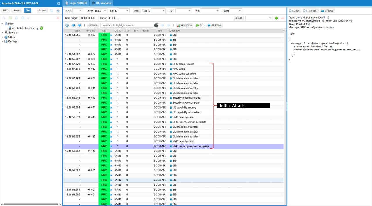
The log shows the overall initial attach process after the UE has already completed cell detection and system information acquisition. The UE first reads the broadcast SIB messages from the NTN cell, including the NTN-related system information needed before access. After that, the UE sends RRC setup request on CCCH-NR, and the gNB responds with RRC setup. This establishes the initial RRC signaling path between the UE and the gNB.
Once RRC setup is complete, the UE sends RRC setup complete and then starts NAS signaling through UL information transfer. The following DL information transfer and UL information transfer messages carry the NAS registration and authentication related procedures between the UE and the core network through the gNB. The security mode command and security mode complete messages show that access stratum security is activated successfully.
After security is established, the gNB requests UE capability information using UE capability enquiry, and the UE responds with UE capability information. This allows the gNB to confirm the UE capability before applying the final dedicated configuration. Then the gNB sends RRC reconfiguration, and the UE replies with RRC reconfiguration complete. This indicates that the UE accepted the dedicated radio configuration and completed the initial attach setup.
Overall, this log confirms that the UE successfully moves from NTN cell acquisition to RRC connection setup, NAS signaling, security activation, UE capability exchange, and final RRC reconfiguration. The selected RRC reconfiguration complete message is the final checkpoint showing that the initial attach procedure has completed successfully in the simulated NTN environment.
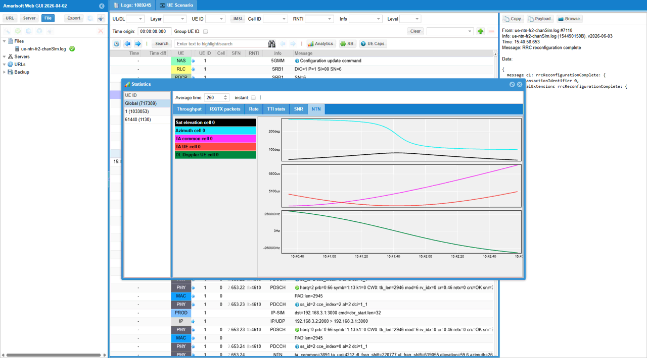
This snapshot shows the NTN statistics window after the UE has completed initial attach and the connection is active. The selected NTN tab is useful because it shows how the satellite geometry and NTN timing values evolve over time, not just whether the UE is connected.
The upper plot shows satellite elevation and azimuth for cell 0. These values represent the apparent satellite direction seen from the UE or reference position. In a LEO scenario, these values are expected to change continuously because the satellite moves quickly relative to the ground. The elevation curve changing over time confirms that the simulated satellite is not static, and the NTN geometry is being updated during the test.
The middle plot shows TA common and TA UE for cell 0. These values represent the timing advance components used to compensate for the long propagation delay in the NTN link. TA common is mainly related to the common satellite and cell geometry, while TA UE represents the UE-specific timing adjustment. The fact that these values change over time is expected for LEO because the satellite-to-ground distance changes as the satellite moves.
The lower plot shows DL Doppler UE for cell 0. This represents the downlink Doppler shift estimated from the satellite motion and link geometry. In this example, the Doppler value changes continuously and crosses through a large range, which is typical for LEO NTN because the relative velocity between the satellite and UE changes during the satellite pass. This confirms that Doppler simulation is active and that the UE is tracking a time-varying NTN radio condition.
Overall, this statistics view confirms that the NTN channel simulation is running dynamically after attach. The UE is not connected through a fixed static channel; instead, the simulator is continuously updating satellite direction, timing advance, and Doppler shift. This is an important verification point for the LEO NTN test because it shows that the UE remains connected while the simulated satellite geometry and radio impairments evolve over time.
RRC / NAS Signaling
SIB19 (NR)
: This is SIB19 containing ephemeris
{
message c1: systemInformation: {
criticalExtensions systemInformation: {
sib-TypeAndInfo {
sib19-v1700: {
ntn-Config-r17 {
ntn-UlSyncValidityDuration-r17 s240,
cellSpecificKoffset-r17 520,
ta-Info-r17 {
ta-Common-r17 62210800
},
ephemerisInfo-r17 orbital-r17: {
semiMajorAxis-r17 8394210402,
eccentricity-r17 0,
periapsis-r17 0,
longitude-r17 248299011,
inclination-r17 0,
meanAnomaly-r17 533258
}
}
}
}
}
}
}
FAQ
I am putting a list of frequently asked questions and answers that would help everybody.
[Q1] why we need channel simulator ?
[A1] It is necessary to simulate the constantly changing real time position of the satellite
[Q2] do we always need to use the channel simulator ?
[A2] Yes for MEO or LEO in which delay and doppler varies relatively in large scale. Maybe optional to GEO in which delay and doppler does not vary widely. (NOTE : You may use the internal channel simulator at the testing phase in quick and easy way, but you can also use an external satellite channel simulator as well).
[Q3] What is the maximum delay simulated by Amarisoft Channel Simulator ?
[A3] Up to several seconds. The maximum value will depend on the sample rate, the value is max_delay in s = 2.147e9 / (sample_rate in Hz). In NB-IoT, for example, the sample rate is usually 1.92 MHz, so the max_delay is around 1118 seconds.
[Q4] What is the minimum configurable altitude of a satellite ?
[A4] The 3GPP encoding for the semi-major axis has a minimum of 6500 km, so a minimum of 122(=6500-6378) km altitude, where 6378 is the radius of the earth
[Q5] For ue_position, ground_position, we allow the altitude with the range of -1000m to 20km, what is the reason to allow negative values ?
[A5] It is to configure altitude below sea level. (https://en.wikipedia.org/wiki/List_of_places_on_land_with_elevations_below_sea_level )