NR SA DMRS - PDSCH, Antenna Port
The purpose of this tutorial is to show you how to configure PDSCH DMRS and Antenna Port in DCI 1_1. PDSCH DMRS (DeModulation Reference Signal) is a kind of reference signal that is used for channel estimation and helps to decode PDSCH. The exact position is determined by following factors.
- RRC parameter configured in DMRS-DownlinkConfig : This determines mostly about the time domain position (i.e, the OFDM symbols) of DMRS and DMRS type (details)
- MIMO configuration configured in DCI : This determines mostly about the frequeny domain position (i.e, the frequency offset of the starting position). (details)
Theoretically, if you put more number of symbols for DMRS, you may get better decoding result (i.e, lower BLER), but the number of the RE (resource elements) for user data (PDSCH) is reduced since some of the symbols are used for DMRS. As a rule of thumb, in most of cases it is recommended to use two symbols for DMRS. If you use only one symbol for DMRS, it is highly likely to have high BLER. If you use more than two symbols for DMRS, you would sacrifice too much in terms of ideal (max) throughput.
Table of Contents
- NR SA DMRS - PDSCH, Antenna Port
- Introduction
- Summary of the Tutorial
- Test Setup
- Key Configuration Parameters
- Test 1 : Table 7.3.1.2.2-1
- Configuration
- Perform the Test
- Log Analysis
- Sub Test 1 : Value = 0
- Sub Test 2 : Value = 1
- Sub Test 3 : Value = 2
- Sub Test 4 : Value = 7
- Sub Test 5 : Value = 9
- Test 2 : Table 7.3.1.2.2-2
- RRC / NAS Signaling
Introduction
The configuration of PDSCH DMRS (Physical Downlink Shared Channel DeModulation Reference Signal) and Antenna Port assignment in DCI 1_1 is a foundational aspect of 5G NR (New Radio) physical layer procedures, directly influencing data channel reliability and throughput. In 5G NR, the PDSCH serves as the primary channel for delivering user data, and its robust decoding relies heavily on accurate channel estimation, which is facilitated by DMRS. The DMRS are specialized reference signals embedded within the PDSCH transmission, enabling the receiving UE (User Equipment) to estimate the wireless channel and properly demodulate downlink data. The position and configuration of DMRS in time and frequency domains are dictated by multiple factors: RRC (Radio Resource Control) signaling, which establishes the overall DMRS configuration in the DMRS-DownlinkConfig, and dynamic parameters conveyed in DCI (Downlink Control Information), which may adjust aspects such as antenna port mapping and frequency offset at transmission time. The selection of DMRS symbol positions, types (Type 1 or Type 2), and the number of symbols allocated, directly impacts both channel estimation quality and the available capacity for user data, requiring careful balancing based on deployment scenarios and desired performance. Antenna port configuration further enables advanced MIMO (Multiple-Input Multiple-Output) schemes, enhancing spectral efficiency and reliability. Configuring these parameters correctly is critical for optimizing link-level performance, minimizing block error rate (BLER), and maximizing throughput, forming a vital part of physical layer optimization in modern 5G networks.
-
Context and Background
- PDSCH DMRS is integral to 5G NR downlink, enabling accurate channel estimation for user data decoding.
- Configuration parameters are managed through a combination of RRC signaling and dynamic DCI assignments.
- Antenna port mapping is essential for supporting MIMO, spatial multiplexing, and beamforming capabilities.
- The balance between DMRS allocation and data REs (Resource Elements) directly affects BLER and system throughput.
-
Relevance and Importance
- Correct configuration of DMRS and antenna ports ensures robust, high-performance 5G data delivery.
- Misconfiguration can lead to degraded link quality, higher error rates, or inefficient resource usage.
- This topic is crucial for engineers involved in 5G NR physical layer development, testing, and optimization.
-
Tutorial Learning Outcomes
- Understand the role and configuration of PDSCH DMRS in 5G NR systems.
- Gain insights into the interaction between RRC and DCI in DMRS and antenna port assignment.
- Learn how to balance channel estimation needs with data throughput requirements.
- Acquire practical knowledge for configuring and optimizing PDSCH DMRS and antenna ports in real-world scenarios.
-
Prerequisite Knowledge
- Familiarity with 5G NR architecture and physical layer concepts.
- Basic understanding of OFDM, resource elements, and MIMO techniques.
- Awareness of RRC and DCI signaling in 5G systems.
Summary of the Tutorial
This tutorial details procedures for low layer DMRS configuration and MIMO testing using Amarisoft callbox, focusing on TS 38.212 Table 7.3.1.2.2-1 and Table 7.3.1.2.2-2. The tests demonstrate how to set up and verify various DMRS patterns and MIMO schemes, including multiple subtests for different DMRS values.
-
Test Setup:
- Uses the default SIM card supplied with the system.
- Does not require complex IP layer configuration.
- Refer to the Configuration Guide for optional changes.
-
Key Configuration Parameters:
- Relevant for DMRS and MIMO: mapping_type, dmrs_add_pos, dmrs_max_len, dmrs_type, dmrs_scid0, dmrs_scid1, dmrs_len, n_dmrs_cdm_groups, dmrs_ports, n_layers.
- Individual setting of these parameters is required in Amarisoft; single-value mappings from 3GPP are not supported.
-
Test 1: Table 7.3.1.2.2-1 (DMRS Configurations for SISO to 4x4 MIMO)
-
Configuration Steps:
- Start from provided config file (gnb-sa-dmrs-7-3-1-2-2-1.cfg), based on gnb-sa.cfg.
- Set N_ANTENNA_DL to 4 to enable up to 4x4 MIMO.
- Individually configure dmrs_type, dmrs_max_len, n_layer, n_dmrs_cdm_groups, dmrs_ports to match required DMRS pattern.
-
Test Execution Procedure:
- Run the test and verify the number of physical antennas using the cell phy command (ANT parameter shows allocated antennas).
- Initiate a call and confirm connection status using the t command.
- For detailed confirmation (number of layers, DMRS pattern), review logs.
-
Log Analysis:
- Check RRC Setup log to confirm DMRS configuration and applied table.
- Verify maxMIMO-Layers in pdsch-ServingCellConfig to ensure the intended maximum number of layers.
- Inspect DCI 1_1 to confirm antenna_ports value matches configuration (e.g., value = 10 for 4x4 MIMO).
-
Subtests (for values 0, 1, 2, 7, 9 in Table 7.3.1.2.2-1):
- For each subtest, set N_ANTENNA_DL to 4 and configure DMRS parameters to match the specific value from the 3GPP table.
- Repeat the procedure:
- Configure parameters individually (as above).
- Run the test, check physical antenna count (cell phy).
- Set up and verify call connection (t command).
- Review DCI 1_1 logs to confirm antenna_ports matches expected value (0, 1, 2, 7, 9).
-
Configuration Steps:
-
Test 2: Table 7.3.1.2.2-2 (Alternative DMRS Patterns)
-
Configuration Steps:
- Start from gnb-sa-dmrs-7-3-1-2-2-2.cfg, based on gnb-sa.cfg.
- Set N_ANTENNA_DL to 4.
- Individually configure dmrs_type, dmrs_max_len, n_layer, n_dmrs_cdm_groups, dmrs_ports for the desired pattern.
-
Test Execution Procedure:
- Run the test, verify physical antenna count using cell phy.
- Set up a call and confirm connection via t command.
- Check logs for confirmation of number of layers and DMRS pattern.
-
Log Analysis:
- Confirm correct table selection and DMRS configuration in the RRC log.
- Check DCI 1_1 to verify antenna_ports value aligns with the intended configuration (e.g., value = 28).
-
Configuration Steps:
General Notes on Test Methodology:
- For every DMRS/MIMO configuration, parameters must be set individually in Amarisoft, not as a single code value.
- Physical antenna count can be checked using cell phy, while dynamic layer usage is best verified through logs.
- Throughput and log analysis help infer actual layer usage during high data rate scenarios.
- DCI 1_1's antenna_ports must be checked for each configuration to ensure correct mapping to the desired DMRS/MIMO scheme.
Test Setup
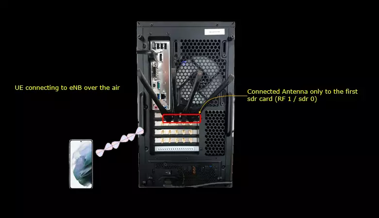
Test setup for this tutorial is as shown below. This is just for low layer testing, you may not need any complicated IP layer setup.
- SIM Card used in this tutorial is the one delivered with the system as it is.
- If you want to change the configuration, The tutorial Configuration Guide would help
Key Configuration Parameters
Followings are important configuration parameters for this tutorial. You may click on the items for the descriptions from Amarisoft documents.
- pdsch : In this link, you would get the descriptions for all the items listed below
- mapping_type
- dmrs_add_pos
- dmrs_max_len
- dmrs_type
- dmrs_scid0
- dmrs_scid1
- dmrs_len
- n_dmrs_cdm_groups
- dmrs_ports
- n_layers
Test 1 : Table 7.3.1.2.2-1
The purpose of this test is to provide an example of how to configure a specific DMRS configuration for SISO/MIMO (from SISO up to 4x4 MIMO). In terms of 3GPP, this configuration is specified by TS 38.212 Table 7.3.1.2.2-1: Antenna port(s) (1000 + DMRS port), dmrs-Type=1, maxLength=1. According to the specification, there are multiple options of DMRS patterns to choose even for the same MIMO scheme. It means just setting the number of antenna may not be enough to specify MIMO scheme accurately. If you don't care much about the detailed DMRS pattern, you can just specify the number of antenna and let Callbox software to choose whatever DMRS pattern it likes. However if you are interested in controlling the details of MIMO configuration, this test would help.
Configuration
I have used gnb-sa-dmrs-7-3-1-2-2-1.cfg which is copied and modified from gnb-sa.cfg

I am using the default mme, ims config as shown below.

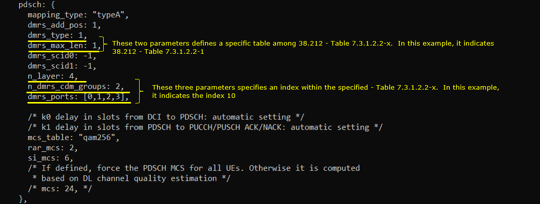
In gnb-sa-dmrs-7-3-1-2-2-1.cfg, it is configured as follows. I set N_ANTENNA_DL to 4 meaning that I want to use max 4x4 MIMO. This mean that the number of physical antenna is set to 4 but it does not necessarily mean that it is only for 4 layer and 4x4 MIMO.

In 3GPP specification, you would just specify a single value that are mapped to a set of property made up of dmrs type, dmrs max length, number of dmrs cdm group and dmrs port numbers. However in Amarisoft callbox, it does not allow you to use the single number value. You need to configure all of these parameters individually. The callbox (gNB) parameter related to this setting are dmrs_type, dmrs_max_len, n_layer, n_dmrs_cdm_groups and dmrs_ports. Among this, dmrs_type and dmrs_max_len determines which table out of 38.212 - Table 7.3.1.2.2-1 through Table 7.3.1.2.2-4 should be used.
This correspond to the value = 10 in 38.212 - Table 7.3.1.2.2-1
Perform the Test
First run the test and check on the number of physical antenna using cell phy command. (

Then setup a call and make it sure that call connection is OK using t command.

Log Analysis
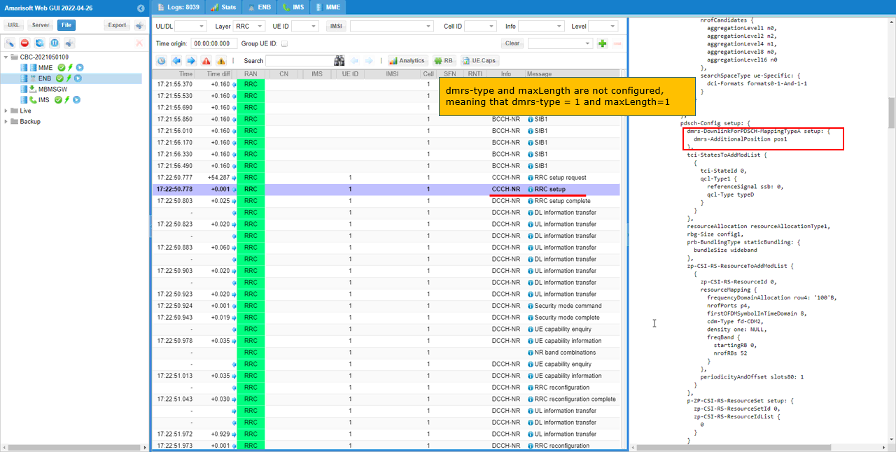
First check RRC log and see if the configuration is done as you intended. In this tutorial, I am checking RRC Setup for PDSCH DMRS Configuration. This parameter determines which table out of 38.212 - Table 7.3.1.2.2-1 through Table 7.3.1.2.2-4 should be applied.
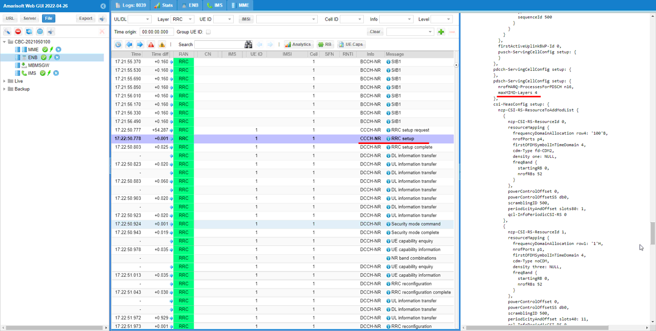
Now check on the maxMIMO-Layers in pdsch-ServingCellConfig. In this specific example, it is set to 4. Be aware that this indicates the maximum number of layer. It does not mean that 4 layers are used all the time. By changing DMRS pattern, gNB can change the number of layers dynamically.
Check DCI 1_1 and see if antenna_ports is set as intended. In this example, antenna_ports is set to 10. It means that dmrs_type, dmrs_max_len, n_layer, n_dmrs_cdm_groups and dmrs_ports values specified in the configuration file indicates antenna_ports (DMRS value in 3GPP) to 10 which is 4x4 MIMO.
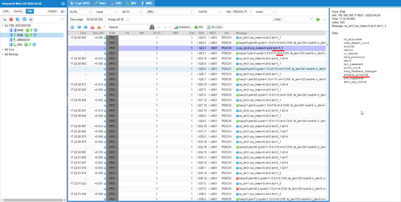
Sub Test 1 : Value = 0
This subtest is to show how to configure and verify of the value = 0 in 38.212 - Table 7.3.1.2.2-1
Configuratio is set as follows. I set N_ANTENNA_DL to 4 meaning that I want to use max 4x4 MIMO. This mean that the number of physical antenna is set to 4 but it does not necessarily mean that it is only for 4 layer and 4x4 MIMO.

In 3GPP specification, you would just specify a single value that are mapped to a set of property made up of dmrs type, dmrs max length, number of dmrs cdm group and dmrs port numbers. However in Amarisoft callbox, it does not allow you to use the single number value. You need to configure all of these parameters individually. The callbox (gNB) parameter related to this setting are dmrs_type, dmrs_max_len, n_layer, n_dmrs_cdm_groups and dmrs_ports. Among this, dmrs_type and dmrs_max_len determines which table out of 38.212 - Table 7.3.1.2.2-1 through Table 7.3.1.2.2-4 should be used.
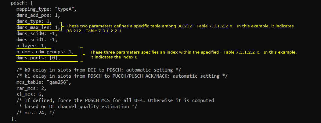
Perform the test.
First run the test and check on the number of physical antenna using cell phy command. (

Then setup a call and make it sure that call connection is OK using t command.

Check DCI 1_1 and see if antenna_ports is set as intended. In this specific example, antenna_ports value is set to 0. You need to compare this value with the dmrs_type, dmrs_max_len, n_layer, n_dmrs_cdm_groups and dmrs_ports and 38.212 - Table 7.3.1.2.2-1 through Table 7.3.1.2.2-4
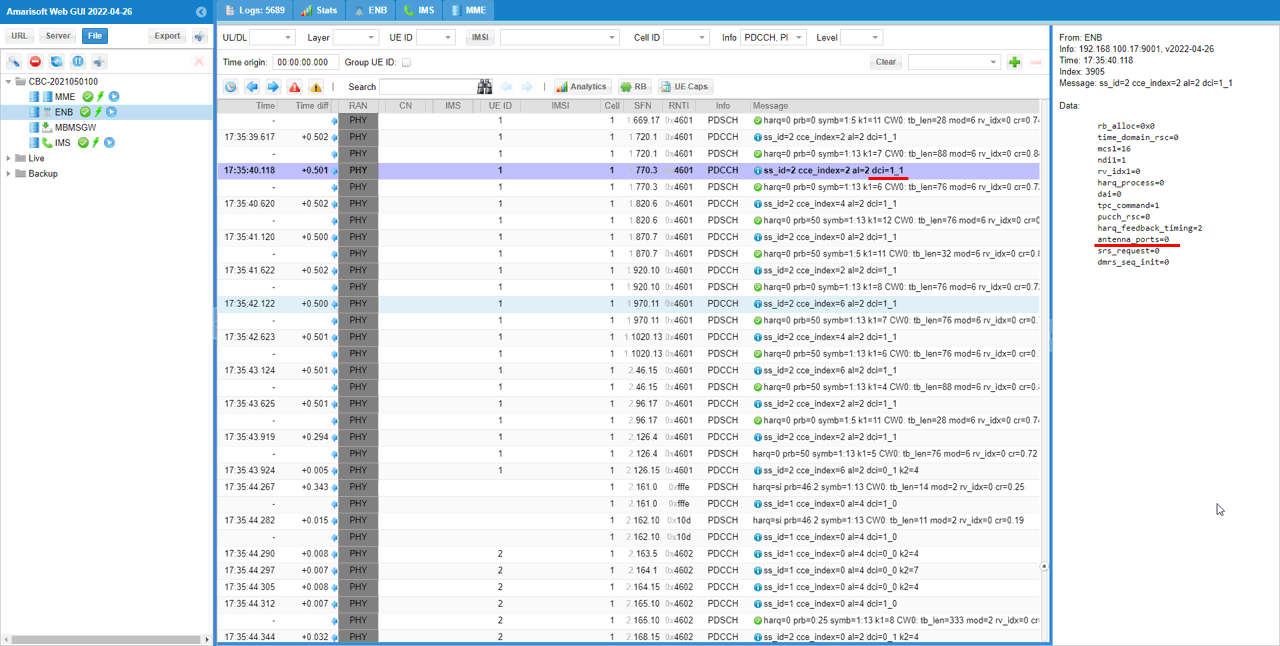
Sub Test 2 : Value = 1
This subtest is to show how to configure and verify of the value = 1 in 38.212 - Table 7.3.1.2.2-1
Configuratio is set as follows. I set N_ANTENNA_DL to 4 meaning that I want to use max 4x4 MIMO. This mean that the number of physical antenna is set to 4 but it does not necessarily mean that it is only for 4 layer and 4x4 MIMO.

In 3GPP specification, you would just specify a single value that are mapped to a set of property made up of dmrs type, dmrs max length, number of dmrs cdm group and dmrs port numbers. However in Amarisoft callbox, it does not allow you to use the single number value. You need to configure all of these parameters individually. The callbox (gNB) parameter related to this setting are dmrs_type, dmrs_max_len, n_layer, n_dmrs_cdm_groups and dmrs_ports. Among this, dmrs_type and dmrs_max_len determines which table out of 38.212 - Table 7.3.1.2.2-1 through Table 7.3.1.2.2-4 should be used.
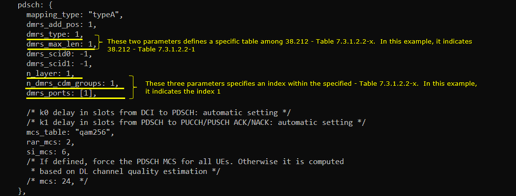
Perform the test.
First run the test and check on the number of physical antenna using cell phy command. (

Then setup a call and make it sure that call connection is OK using t command.

Check DCI 1_1 and see if antenna_ports is set as intended. In this specific example, antenna_ports value is set to 1. You need to compare this value with the dmrs_type, dmrs_max_len, n_layer, n_dmrs_cdm_groups and dmrs_ports and 38.212 - Table 7.3.1.2.2-1 through Table 7.3.1.2.2-4
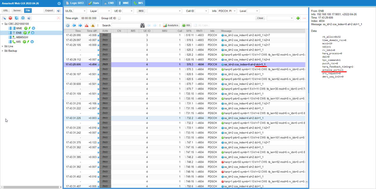
Sub Test 3 : Value = 2
This subtest is to show how to configure and verify of the value = 2 in 38.212 - Table 7.3.1.2.2-1
Configuratio is set as follows. I set N_ANTENNA_DL to 4 meaning that I want to use max 4x4 MIMO. This mean that the number of physical antenna is set to 4 but it does not necessarily mean that it is only for 4 layer and 4x4 MIMO.

In 3GPP specification, you would just specify a single value that are mapped to a set of property made up of dmrs type, dmrs max length, number of dmrs cdm group and dmrs port numbers. However in Amarisoft callbox, it does not allow you to use the single number value. You need to configure all of these parameters individually. The callbox (gNB) parameter related to this setting are dmrs_type, dmrs_max_len, n_layer, n_dmrs_cdm_groups and dmrs_ports. Among this, dmrs_type and dmrs_max_len determines which table out of 38.212 - Table 7.3.1.2.2-1 through Table 7.3.1.2.2-4 should be used.
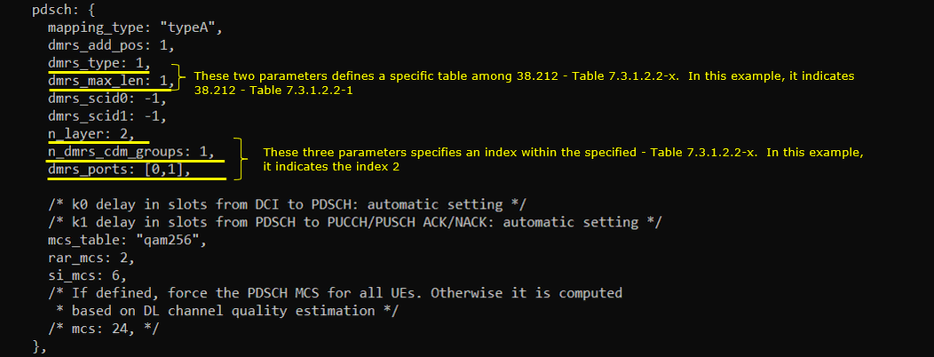
Perform the test.
First run the test and check on the number of physical antenna using cell phy command. (

Then setup a call and make it sure that call connection is OK using t command.

Check DCI 1_1 and see if antenna_ports is set as intended. In this specific example, antenna_ports value is set to 2. You need to compare this value with the dmrs_type, dmrs_max_len, n_layer, n_dmrs_cdm_groups and dmrs_ports and 38.212 - Table 7.3.1.2.2-1 through Table 7.3.1.2.2-4
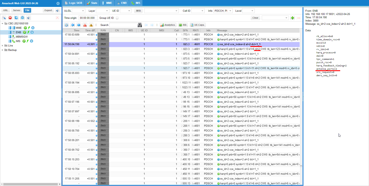
Sub Test 4 : Value = 7
This subtest is to show how to configure and verify of the value = 7 in 38.212 - Table 7.3.1.2.2-1
Configuratio is set as follows. I set N_ANTENNA_DL to 4 meaning that I want to use max 4x4 MIMO. This mean that the number of physical antenna is set to 4 but it does not necessarily mean that it is only for 4 layer and 4x4 MIMO.

In 3GPP specification, you would just specify a single value that are mapped to a set of property made up of dmrs type, dmrs max length, number of dmrs cdm group and dmrs port numbers. However in Amarisoft callbox, it does not allow you to use the single number value. You need to configure all of these parameters individually. The callbox (gNB) parameter related to this setting are dmrs_type, dmrs_max_len, n_layer, n_dmrs_cdm_groups and dmrs_ports. Among this, dmrs_type and dmrs_max_len determines which table out of 38.212 - Table 7.3.1.2.2-1 through Table 7.3.1.2.2-4 should be used.
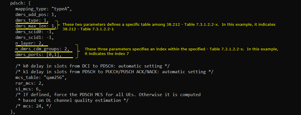
Perform the test.
First run the test and check on the number of physical antenna using cell phy command. (

Then setup a call and make it sure that call connection is OK using t command.

Check DCI 1_1 and see if antenna_ports is set as intended. In this specific example, antenna_ports value is set to 7. You need to compare this value with the dmrs_type, dmrs_max_len, n_layer, n_dmrs_cdm_groups and dmrs_ports and 38.212 - Table 7.3.1.2.2-1 through Table 7.3.1.2.2-4
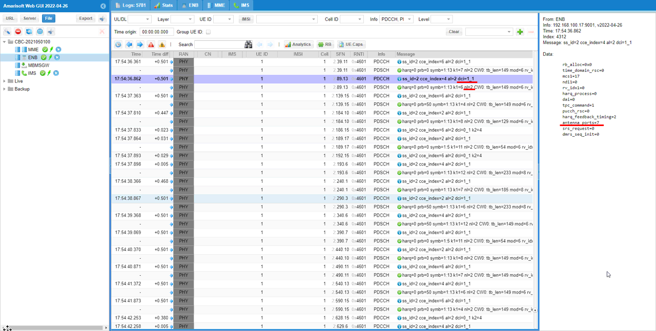
Sub Test 5 : Value = 9
This subtest is to show how to configure and verify of the value = 9 in 38.212 - Table 7.3.1.2.2-1
Configuratio is set as follows. I set N_ANTENNA_DL to 4 meaning that I want to use max 4x4 MIMO. This mean that the number of physical antenna is set to 4 but it does not necessarily mean that it is only for 4 layer and 4x4 MIMO.

In 3GPP specification, you would just specify a single value that are mapped to a set of property made up of dmrs type, dmrs max length, number of dmrs cdm group and dmrs port numbers. However in Amarisoft callbox, it does not allow you to use the single number value. You need to configure all of these parameters individually. The callbox (gNB) parameter related to this setting are dmrs_type, dmrs_max_len, n_layer, n_dmrs_cdm_groups and dmrs_ports. Among this, dmrs_type and dmrs_max_len determines which table out of 38.212 - Table 7.3.1.2.2-1 through Table 7.3.1.2.2-4 should be used.
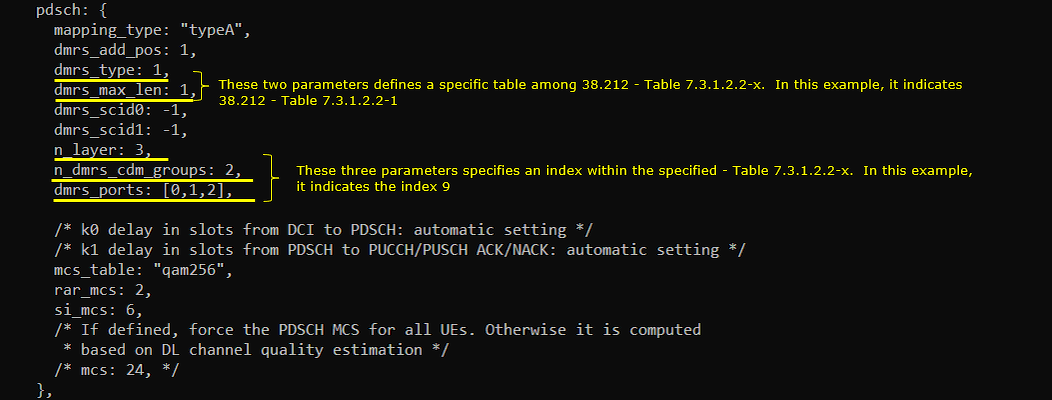
Perform the test.
First run the test and check on the number of physical antenna using cell phy command. (

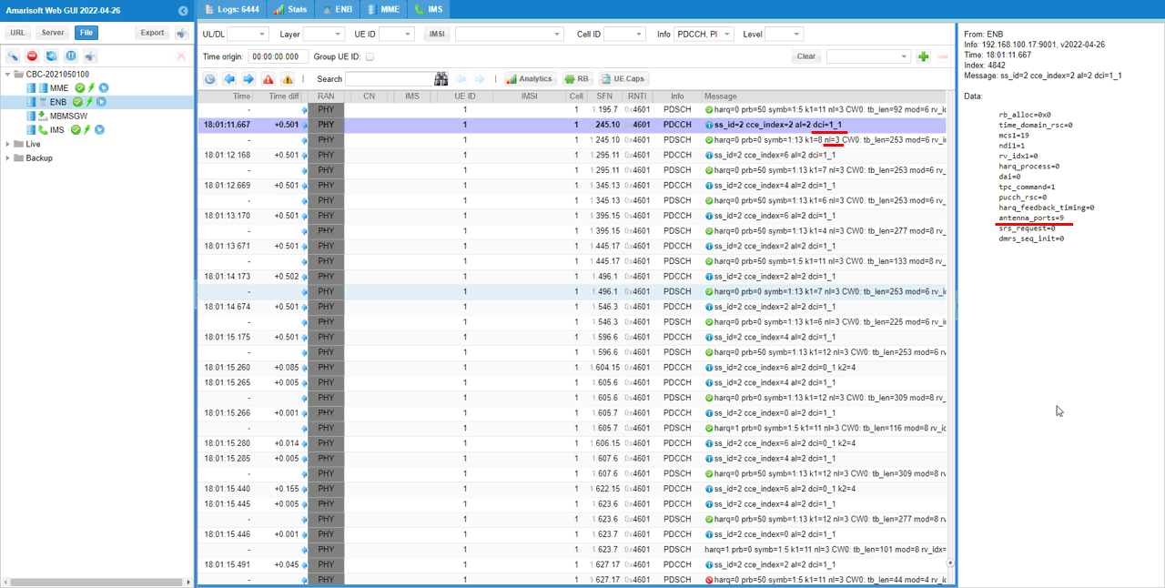
Then setup a call and make it sure that call connection is OK using t command.

Check DCI 1_1 and see if antenna_ports is set as intended. In this specific example, antenna_ports value is set to 9. You need to compare this value with the dmrs_type, dmrs_max_len, n_layer, n_dmrs_cdm_groups and dmrs_ports and 38.212 - Table 7.3.1.2.2-1 through Table 7.3.1.2.2-4
Test 2 : Table 7.3.1.2.2-2
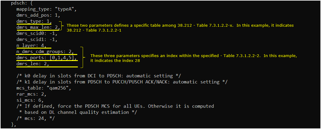
This test is to show how to configure DMRS patterns of 38.212 - Table 7.3.1.2.2-2 and verify it . You can configure different DMRS pattern value from the table by setting n_dmrs_cdm_groupds, dmrs_ports, dmrs_len
Configuration
I have used gnb-sa-dmrs-7-3-1-2-2-2.cfg which is copied and modified from gnb-sa.cfg

I am using the default mme, ims config as shown below.

In gnb-sa-dmrs-7-3-1-2-2-2.cfg, it is configured as follows. I set N_ANTENNA_DL to 4 meaning that I want to use max 4x4 MIMO. This mean that the number of physical antenna is set to 4 but it does not necessarily mean that it is only for 4 layer and 4x4 MIMO.

In 3GPP specification, you would just specify a single value that are mapped to a set of property made up of dmrs type, dmrs max length, number of dmrs cdm group and dmrs port numbers. However in Amarisoft callbox, it does not allow you to use the single number value. You need to configure all of these parameters individually. The callbox (gNB) parameter related to this setting are dmrs_type, dmrs_max_len, n_layer, n_dmrs_cdm_groups and dmrs_ports. Among this, dmrs_type and dmrs_max_len determines which table out of 38.212 - Table 7.3.1.2.2-1 through Table 7.3.1.2.2-4 should be used.
Perform the Test
First run the test and check on the number of physical antenna using cell phy command. (

Then setup a call and make it sure that call connection is OK using t command.

Log Analysis
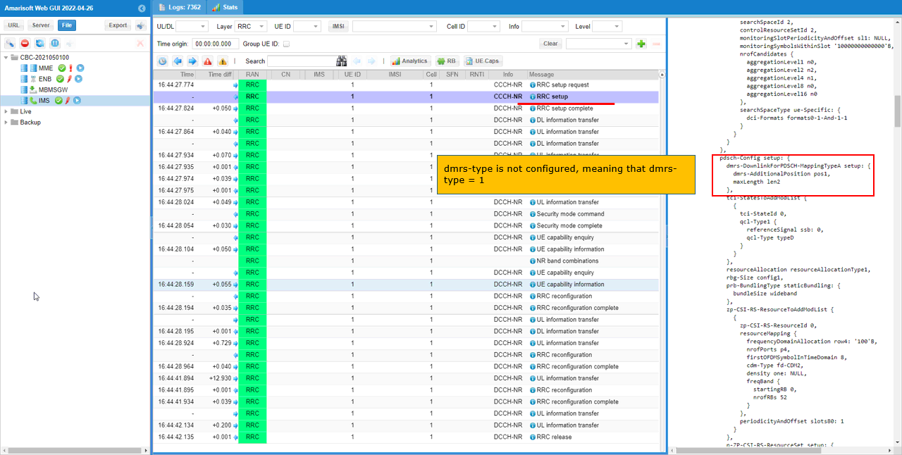
First check RRC log and see if the configuration is done as you intended. In this tutorial, I am checking RRC Setup for PDSCH DMRS Configuration. This parameter determines which table out of 38.212 - Table 7.3.1.2.2-1 through Table 7.3.1.2.2-4 should be applied.
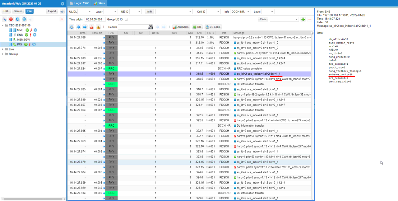
Check DCI 1_1 and see if antenna_ports is set as intended. In this specific example, antenna_ports value is set to 28. You need to compare this value with the dmrs_type, dmrs_max_len, n_layer, n_dmrs_cdm_groups and dmrs_ports and 38.212 - Table 7.3.1.2.2-1 through Table 7.3.1.2.2-4
RRC / NAS Signaling
MIB(SA)
: This is MIB message sent by gNB (
MIB ::= SEQUENCE {
...
dmrs-TypeA-Position ENUMERATED {pos2, pos3},
...
}
RrcSetup(SA)
: This is the RrcSetup message sent by gNB to configure NR SA. (
{
message c1: rrcSetup: {
rrc-TransactionIdentifier 0,
criticalExtensions rrcSetup: {
radioBearerConfig {
...
},
masterCellGroup {
cellGroupId 0,
rlc-BearerToAddModList {
...
},
mac-CellGroupConfig {
...
},
physicalCellGroupConfig {
pdsch-HARQ-ACK-Codebook dynamic
},
spCellConfig {
spCellConfigDedicated {
initialDownlinkBWP {
pdcch-Config setup: {
...
},
pdsch-Config setup: {
dmrs-DownlinkForPDSCH-MappingTypeA setup: {
dmrs-AdditionalPosition pos1
},
...
},
firstActiveDownlinkBWP-Id 0,
uplinkConfig {
initialUplinkBWP {
pucch-Config setup: {
...
},
pusch-Config setup: {
txConfig codebook,
dmrs-UplinkForPUSCH-MappingTypeA setup: {
dmrs-AdditionalPosition pos1,
transformPrecodingDisabled {
}
},
...
},
srs-Config setup: {
...
},
firstActiveUplinkBWP-Id 0,
pusch-ServingCellConfig setup: {
}
},
pdcch-ServingCellConfig setup: {
},
pdsch-ServingCellConfig setup: {
...
},
csi-MeasConfig setup: {
...
}
}
},
tag-Id 0