NR SA DL MIMO
The purpose of this tutorial is to show you how to configure and test 8x8 DL MIMO which requires 2 CW(Code words) and 8 Layers.
Table of Contents
- NR SA DL MIMO
- Introduction
- Summary of the Tutorial
- Test Setup
- Key Configuration Parameters
- Test 1 : 8x8 MIMO - 2 CW, 8 Layers
- Test 2 : 8x8 MIMO - 2 CW, 8 Layers with PDSCH Precoding
- Test 3 : 8x8 MIMO - 2 CW, 8 Layers with channel Matrix
- Test 4 : Channel Matrix Analysis : 8x8 MIMO - 2 CW, 8 Layers with PDSCH Precoding
- Test 5 : Channel Matrix Analysis : 8x8 MIMO - 2 CW, 8 Layers with channel matrix
- Test 6 : 8x8 MIMO - 2 CW, 8 Layers over the antenna - Channel Coefficient Analysis
Introduction
Multiple Input Multiple Output (MIMO) technology is a cornerstone of modern wireless communication systems, enabling substantial improvements in throughput, spectral efficiency, and link reliability. In the context of 5G New Radio (NR), Downlink (DL) MIMO leverages advanced antenna configurations to transmit multiple data streams concurrently, thereby maximizing the utilization of available spectrum. The 8x8 DL MIMO configuration signifies the use of eight transmit (Tx) and eight receive (Rx) antennas, supporting up to 8 spatial layers and two code words. This advanced setup allows for significantly higher data rates and improved signal robustness compared to traditional 2x2 or 4x4 arrangements, which are commonly found as default capabilities in most commercial NR deployments. Architecturally, implementing 8x8 DL MIMO involves complex signal processing at both the gNB (next-generation NodeB or base station) and the UE (User Equipment), including advanced precoding, channel estimation, and layer mapping strategies. The relevance of this technology becomes even more pronounced as data-intensive applications like eMBB. This tutorial provides a step-by-step guide on configuring and testing 8x8 DL MIMO, which, until recently, was not widely adopted or documented, offering practitioners the opportunity to extend network capabilities beyond the default 2x2 or 4x4 MIMO configurations in FR1 and FR2 frequency ranges.
-
Context and Background
- 5G NR introduces advanced MIMO techniques to enhance wireless performance and capacity.
- Default MIMO capabilities (2x2, 4x4 for FR1; 2x2 for FR2) are widely documented and typically preconfigured in commercial networks.
- 8x8 DL MIMO represents a higher-order spatial multiplexing scheme, requiring both network and device support for two code words and eight spatial layers.
- This configuration demands more sophisticated hardware and software for beamforming, channel estimation, and scheduling on both gNB and UE sides.
-
Relevance and Importance of the Tutorial
- 8x8 DL MIMO is a recent enhancement in NR deployments, unlocking significant improvements in peak data rates and spectral efficiency.
- Understanding how to configure and validate 8x8 DL MIMO is essential for engineers and network professionals aiming to maximize 5G network performance.
- This tutorial fills the knowledge gap not covered by standard documentation or existing tutorials focused on lower-order MIMO configurations.
-
Learning Outcomes
- Comprehend the architectural principles and operational mechanisms of 8x8 DL MIMO in 5G NR.
- Gain practical skills in configuring both network and device parameters to enable 8x8 MIMO operation.
- Develop the ability to test and verify multi-layer, multi-codeword transmission and analyze system performance improvements.
- Acquire insight into troubleshooting and optimization strategies when deploying high-order MIMO configurations.
-
Prerequisite Knowledge and Skills
- Familiarity with 5G NR architecture, protocols, and physical layer concepts.
- Understanding of basic MIMO principles, including spatial multiplexing and codeword/layer mapping.
- Experience with network configuration tools and relevant testing equipment or simulators.
- Basic knowledge of RF propagation, antenna arrays, and signal processing is advantageous.
Summary of the Tutorial
This tutorial describes a series of test procedures for evaluating and analyzing 8x8 MIMO (Multiple Input Multiple Output) performance using Amarisoft products, focusing on configuration, execution, and channel analysis under various scenarios.
-
Test 1: 8x8 MIMO - 2 Codewords, 8 Layers
- Configure the gNB using gnb-nr-8layers.cfg.
- Set the number of downlink antennas (N_ANTENNA_DL) to 8 and enable 2 Code Word operation (ENABLE_2CW = 1).
- Ensure adequate SDR hardware is present and enabled for 8 antennas.
- Set appropriate bandwidth and frequency, verifying compatibility with the selected band and DUT.
- Main 8x8 MIMO configuration:
- Enable two codewords (two_codewords: true), set n_layer to 8.
- Configure 8 DMRS ports for PDSCH: n_dmrs_cdm_groups = 2, dmrs_ports = [0,1,2,3,4,5,6,7], dmrs_len = 2.
- Verify cell configuration using cell phy commands for DL antennas and number of layers.
- Power on UE, establish a call, and check that ri = 8 is reported, confirming 8-layer PDSCH.
- Log analysis includes checking the reflection of configuration in signaling, UE capability for 8 layers, and DCI/PDSCH log prints for correct transport block and antenna port assignments.
-
Test 2: 8x8 MIMO - 2 Codewords, 8 Layers with PDSCH Precoding
- Configure the gNB using gnb-nr-8layers-precoding-20mhz.cfg, with N_ANTENNA_DL = 8, ENABLE_2CW = 1, and a narrower bandwidth (20 MHz).
- Verify SDR card support for 8 antennas.
- Standard 8x8 MIMO parameters as in Test 1.
- Key difference: Enable precoding_matrix for PDSCH based on 3GPP TS 36.101 annex B.1 to simulate a MIMO channel environment.
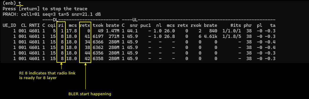
- Check cell configuration and verify UE reports ri = 8.
- Observe BLER performance at different MCS levels, noting the impact of the simulated MIMO channel on error rates.
-
Test 3: 8x8 MIMO - 2 Codewords, 8 Layers with Channel Matrix
- Configure the gNB using gnb-nr-8layers-chansim-precoding-20mhz.cfg.
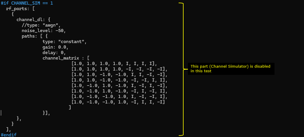
- Set N_ANTENNA_DL = 8, ENABLE_2CW = 1, and CHANNEL_SIM = 1 to enable channel simulation; disable PDSCH precoding (PDSCH_PRECODE = 0).
- Configure channel_dl and channel_matrix with a MIMO matrix as per TS 36.101 annex B.1.
- Standard MIMO parameters as in previous tests.
- Check cell configuration, establish a call, and monitor ri = 8.
- Observe BLER and performance trends similar to Test 2, since channel simulation affects all downlink channels.
-
Test 4: Channel Matrix Analysis – 8x8 MIMO with PDSCH Precoding
- Analysis procedure, based on logs from Test 2, using UEsim with phy.signal = 1 to capture IQ data for each PDSCH.
- Steps include:
- Visualize overall constellation of a PDSCH.
- Analyze PDSCH channel impulse response for all TX/RX antenna pairs.
- Examine magnitude and phase per channel; focus on individual channels as needed for clarity.
- Plot and analyze the channel coefficient for each DMRS RE between all TX and RX antennas.
- Isolate and inspect the channel coefficient for any specific TX-RX antenna pair.
-
Test 5: Channel Matrix Analysis – 8x8 MIMO with Channel Matrix
- Analysis procedure, based on logs from Test 3, using UEsim with phy.signal = 1.
- Steps include:
- Check PDSCH constellation.
- Analyze channel magnitude/phase and impulse response for all TX/RX pairs.
- Visualize channel coefficients for each DMRS RE between each antenna pair.
- Isolate and examine specific TX-RX antenna pair coefficients.
-
Test 6: 8x8 MIMO - 2 Codewords, 8 Layers over the Antenna (Radiative Condition) – Channel Coefficient Analysis
- Configure the gNB with gnb-nr-8layers-20mhz-ota.cfg, setting N_ANTENNA_DL = 8 and ENABLE_2CW = 1. Channel simulation is disabled (CHANNEL_SIM = 0).
- Test is performed over the air (radiative conditions) rather than via cable or simulation.
- Ensure SDR cards are enabled appropriately.
- Apply standard 8x8 MIMO parameters; do not enable precoding_matrix.
- Verify cell configuration and establish a call; UE should report ri = 8.
- Log analysis is performed as in previous tests (using UEsim and phy.signal = 1):
- Visualize constellation, channel impulse response, and magnitude/phase for all TX/RX antenna pairs.
- Isolate and analyze channel coefficients for specific antenna pairs.
General Methodologies:
- For each test, ensure correct gNB configuration, hardware setup, and compatibility with the DUT (Device Under Test).
- Key configuration parameters include: enabling two codewords, setting number of layers to 8, configuring DMRS ports/groups, and, where relevant, enabling channel simulation or PDSCH precoding.
- Verification steps include checking cell configuration, monitoring reported ri in the UE, and analyzing logs for proper resource and transport block allocation.
- Channel analysis is performed using captured IQ data with UEsim, focusing on constellation, impulse response, magnitude/phase, and channel coefficients between antenna pairs.
- Comparative analysis is performed between simulated and real (radiative) channel conditions.
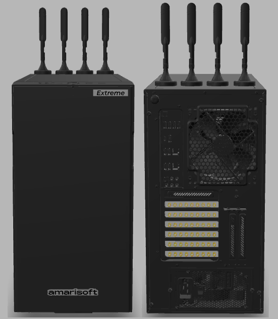
Test Setup
Since this test requires huge amount of computing resources, you need to use one of the high end Amarisoft product for it.
Key Configuration Parameters
Followings are important configuration parameters for this tutorial. You may click on the items for the descriptions from Amarisoft documents.
Test 1 : 8x8 MIMO - 2 CW, 8 Layers
This test is to show how to configure and test 8x8 MIMO. The major configuration is about enabling 2 code words and setting proper PDSCH DMRS configuration to match the 8 DMRS ports.
Configuration
I used the gnb-nr-8layers.cfg on gNB

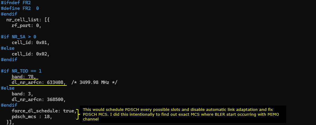
In gnb-nr-8layers.cfg , the number of DL antenna is set to 8 (N_ANTENNA_DL = 8) and 2 Code Word flag is enabled (ENABLE_2CW = 1).

Make it sure that you have enough number of SDR cards that can support 8 antenna and all of those necessary SDR cards are enabled.

Configure any bandwidth and frequency.(
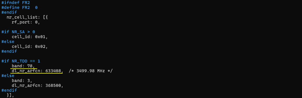
Followings are main configuration for 8x8 MIMO. First 2 codewords are enabled (two_codewords: true), number of layer is set to 8 (n_layer : N_NR_ANTENNA_DL which is set to 8). In order to set 8 DMRS ports for PDSCH, n_dmrs_cdm_groups is set to 2, dmrs_ports is set to [0,1,2,3,4,5,6,7] and dmrs_len is set to 2.

Perform the Test
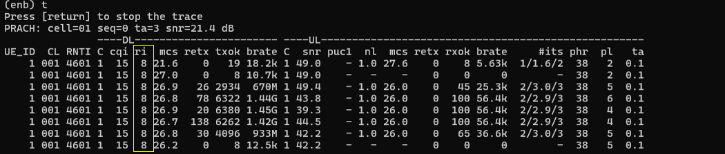
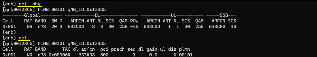
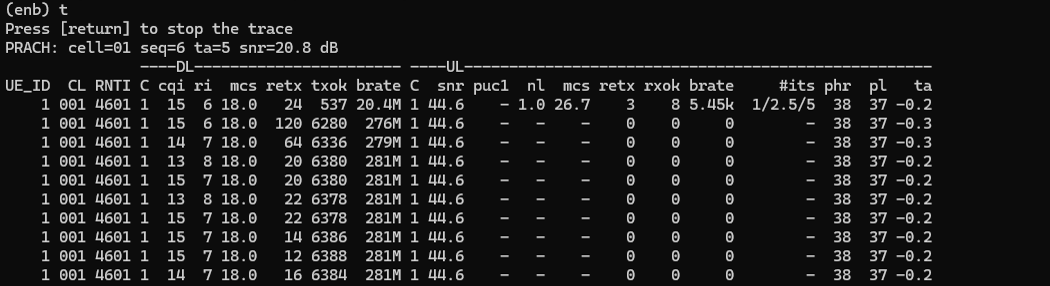
Check if the cell is configured as intended. The important thing in this test is Downlink configuration. Check out the number of DL ANT and NL(number of layers) with cell phy command.

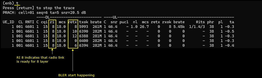
Power on UE and establish call. Make it sure that you see ri = 8 which indicates that UE is expecting 8 layer PDSCH. gNB is supposed to transmit 8 layered PDSCH in response to this ri report.
Log Analysis
Now let's look into the log and see how the configuration is reflected in signaling message.
The first thing you may check is the maxLength of pdsch dmrs in RRC Setup. This is important because it is one of the key parameter to determine the type of dmrs antenna port table. (
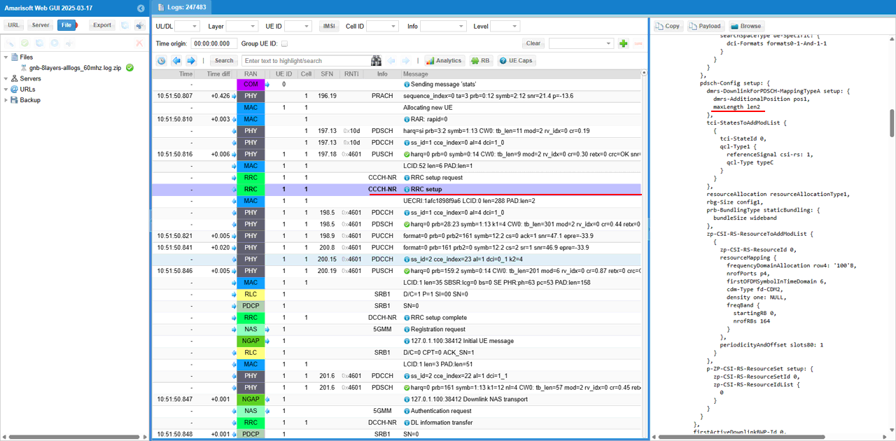
Next check if DUT (UE) has the capability of 8 layers( 8 x 8 MIMO) in UE capability Information message.
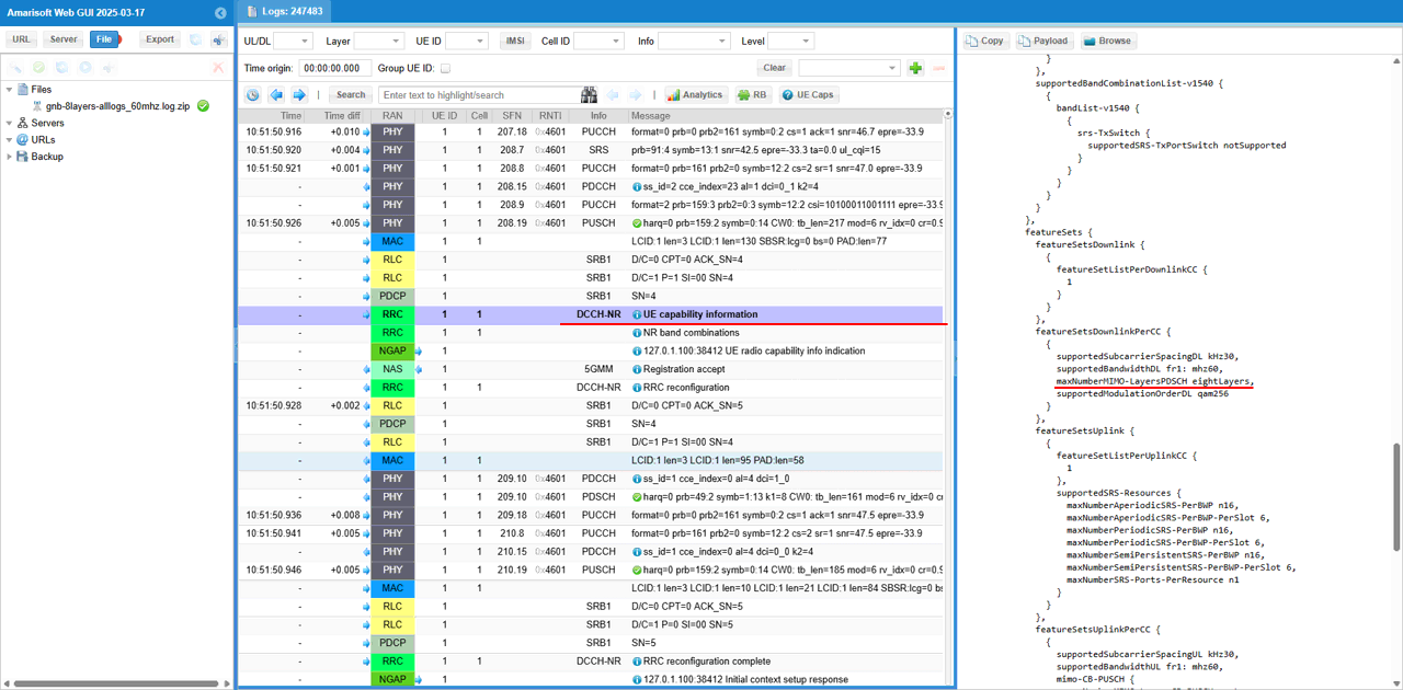
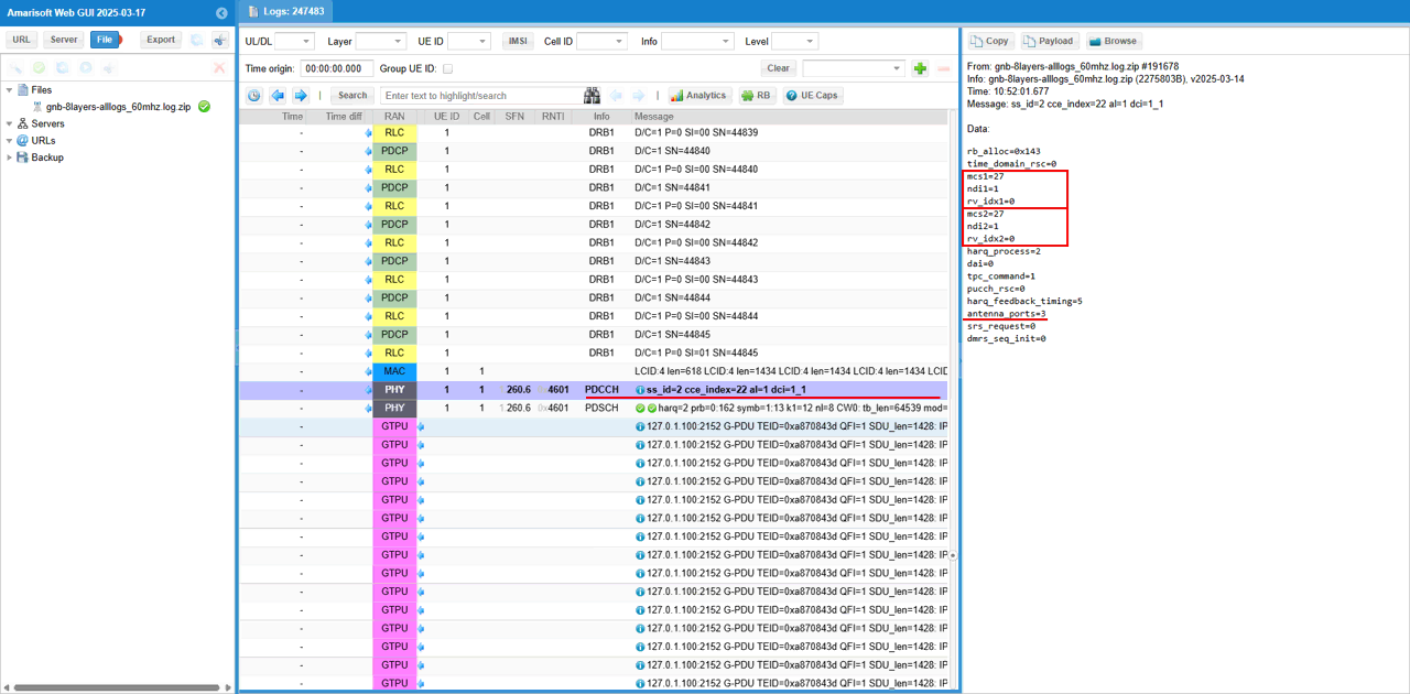
Now let's checkout if 2 cw(codeword) and corresponding antenna port is used. First check point for this is the informations in DCI. You see the two sents of mcs, ndi, rv_idx which indicates that two transport block (2 codewords) are scheduled. With antenna_ports field in the DCI, you can confirm on the number of antenna ports that are used for each layer.
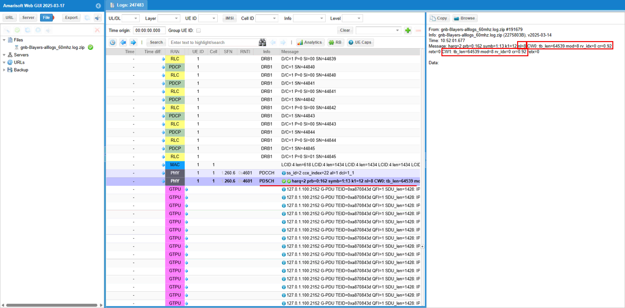
The second check point for 8x8 MIMO is from the log print for PDSCH. You see nl=8 which indicates that number of layer (nl) is 8. And you see there are two sets of tb_len(transport block size in bytes , mod (modulation scheme), rv_idx(Redundancy Version), cr(Code Rate) for two codewords (CW0, CW1)
Test 2 : 8x8 MIMO - 2 CW, 8 Layers with PDSCH Precoding
This test is to show how to configure and test 8x8 MIMO with PDSCH Precoding. The basic configuration to setup 8x8 MIMO is same as in Test 1 (except the channel bandwidth) which is about enabling 2 code words and setting proper PDSCH DMRS configuration to match the 8 DMRS ports. The key differnece from Test 1 is that we will apply precoding for PDSCH in this test. The purpose of this precoding is to simulate MIMO channel environment. Since the test setup for this test is over RF cable connection with one to one mapping between TX and RX antenna (e.g, TX1 --> RX1, TX2 --> RX2 and so on), it can test for 8 layers but it will not accurately simulate MIMO radio channel where all TX antenna interfact with all RX antenna.
Configuration
I used the gnb-nr-8layers-precoding-20mhz.cfg on gNB

In gnb-nr-8layers-precoding-20mhz.cfg, the number of DL antenna is set to 8 (N_ANTENNA_DL = 8) and 2 Code Word flag is enabled (ENABLE_2CW = 1). In this test, I set the bandwidth to a narrow band (20 Mhz) in order not to introduce any other factors that may interfere the test (e.g, CPU overload).

Make it sure that you have enough number of SDR cards that can support 8 antenna and all of those necessary SDR cards are enabled.
Configure any bandwidth and frequency.(
Followings are main configuration for 8x8 MIMO. First 2 codewords are enabled (two_codewords: true), number of layer is set to 8 (n_layer : N_NR_ANTENNA_DL which is set to 8). In order to set 8 DMRS ports for PDSCH, n_dmrs_cdm_groups is set to 2, dmrs_ports is set to [0,1,2,3,4,5,6,7] and dmrs_len is set to 2.
The important configuration for this specific test is precoding_matrix part. I configured the precoding_matrix based on the basic 8x8 MIMO channel defined in 3GPP TS 36.101 annex B.1.

Perform the Test
Check if the cell is configured as intended. The important thing in this test is Downlink configuration. Check out the number of DL ANT and NL(number of layers) with cell phy command.
Power on UE and establish call. Make it sure that you see ri = 8 which indicates that UE is expecting 8 layer PDSCH. gNB is supposed to transmit 8 layered PDSCH in response to this ri report.
(
Test 3 : 8x8 MIMO - 2 CW, 8 Layers with channel Matrix
This test is to show how to configure and test 8x8 MIMO with channel matrix. The basic configuration to setup 8x8 MIMO is same as in Test 1 (except the channel bandwidth) which is about enabling 2 code words and setting proper PDSCH DMRS configuration to match the 8 DMRS ports. The key differnece from Test 1 is that we will apply precoding for PDSCH in this test. The purpose of this precoding is to simulate MIMO channel environment. Since the test setup for this test is over RF cable connection with one to one mapping between TX and RX antenna (e.g, TX1 --> RX1, TX2 --> RX2 and so on), it can test for 8 layers but it will not accurately simulate MIMO radio channel where all TX antenna interfact with all RX antenna.
Configuration
I used the gnb-nr-8layers-chansim-precoding-20mhz.cfg on gNB

In gnb-nr-8layers-chansim-precoding-20mhz.cfg, the number of DL antenna is set to 8 (N_ANTENNA_DL = 8) and 2 Code Word flag is enabled (ENABLE_2CW = 1). In this test, I set the bandwidth to a narrow band (20 Mhz) in order not to introduce any other factors that may interfere the test (e.g, CPU overload). Here I enabled channel sim flag (CHANNEL_SIM = 1) and create/disable PDSCH precoding flag (PDSCH_PRECODE = 0).

Make it sure that you have enough number of SDR cards that can support 8 antenna and all of those necessary SDR cards are enabled.
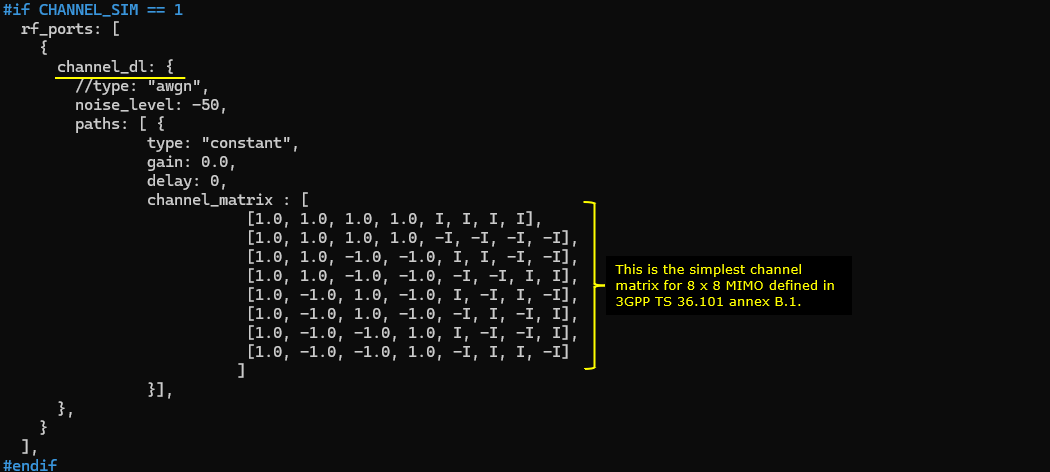
The key setting in this test is the following. channel_dl (Downlink Channel Simulation) is enabled and channel_matrix is configured with a MIMO channel matrix as specified by TS 36.101 annex B.1
Configure any bandwidth and frequency.(
Followings are main configuration for 8x8 MIMO. First 2 codewords are enabled (two_codewords: true), number of layer is set to 8 (n_layer : N_NR_ANTENNA_DL which is set to 8). In order to set 8 DMRS ports for PDSCH, n_dmrs_cdm_groups is set to 2, dmrs_ports is set to [0,1,2,3,4,5,6,7] and dmrs_len is set to 2.
The important configuration for this specific test is precoding_matrix part. I configured the precoding_matrix based on the basic 8x8 MIMO channel defined in 3GPP TS 36.101 annex B.1.

Perform the Test
Check if the cell is configured as intended. The important thing in this test is Downlink configuration. Check out the number of DL ANT and NL(number of layers) with cell phy command.
Power on UE and establish call. Make it sure that you see ri = 8 which indicates that UE is expecting 8 layer PDSCH. gNB is supposed to transmit 8 layered PDSCH in response to this ri report.
(
Test 4 : Channel Matrix Analysis : 8x8 MIMO - 2 CW, 8 Layers with PDSCH Precoding
This test is not really any new test. It is more of analysis for a previous test (Test 2). It is about the analysis of radio channel from each & every TX antenna to each & every RX antenna. I separated this analysis from the previous test since this is too lengthy and would look too complicated.
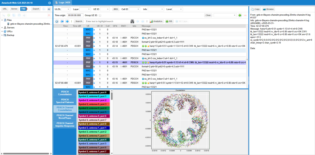
This is based on the log of Test 2 , captured by UEsim with the log option phy.signal = 1 which is to capture IQ data for every PDSCH..
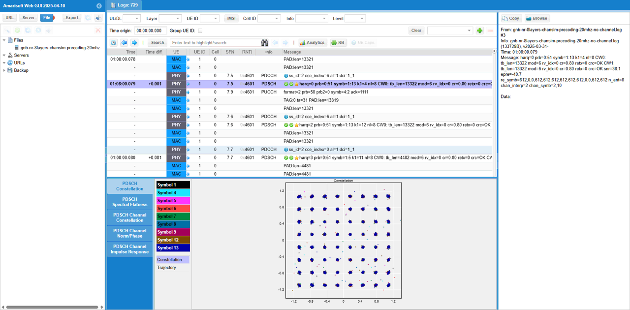
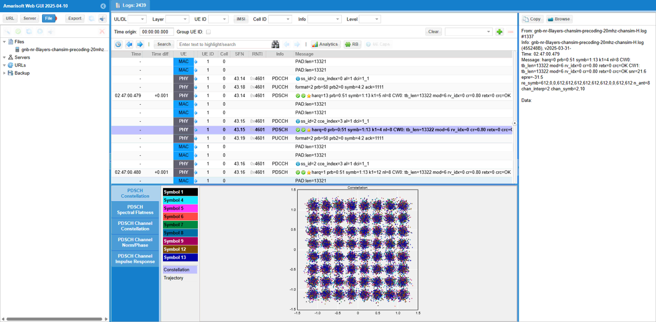
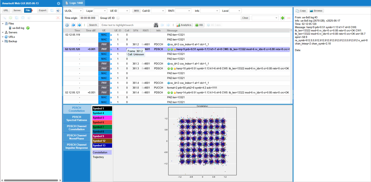
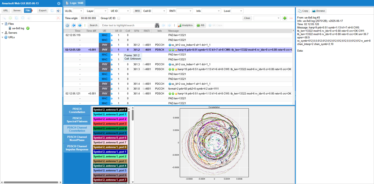
First pick an any PDSCH and check out overall constellation.
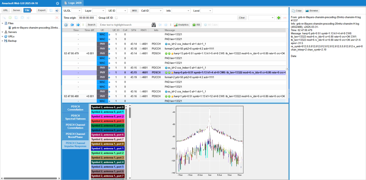
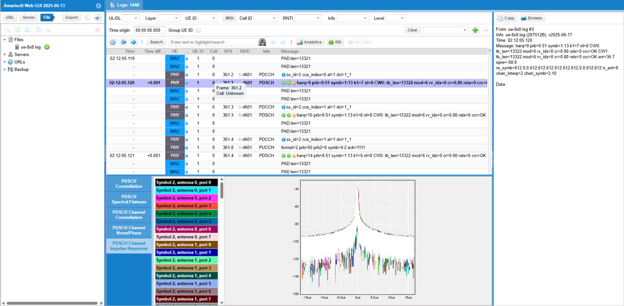
Then you may check out PDSCH Channel Impulse Response. (
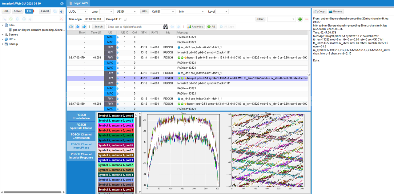
In the same way, you can check out magnitue and phase of each channel(
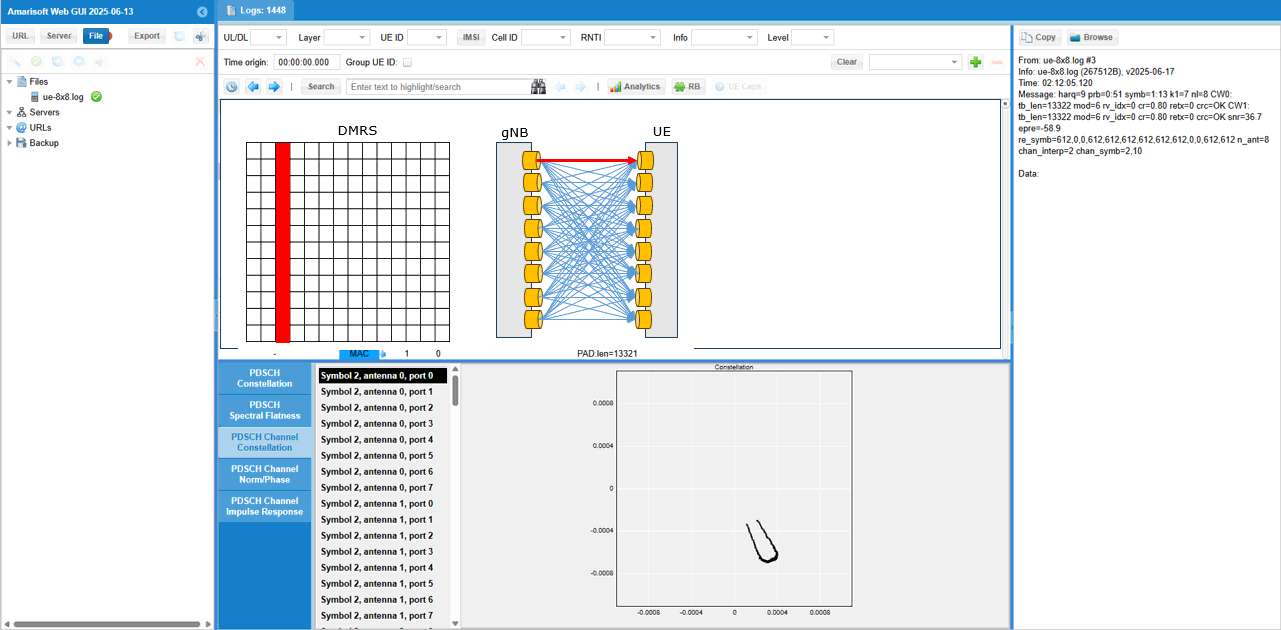
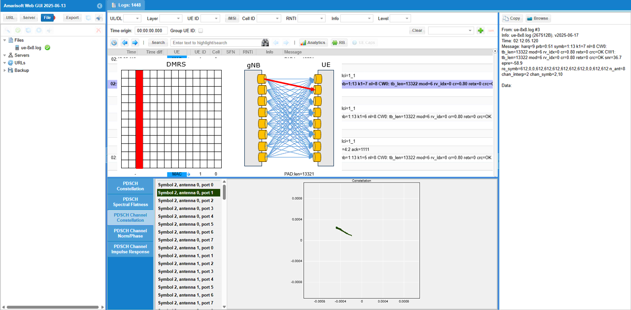
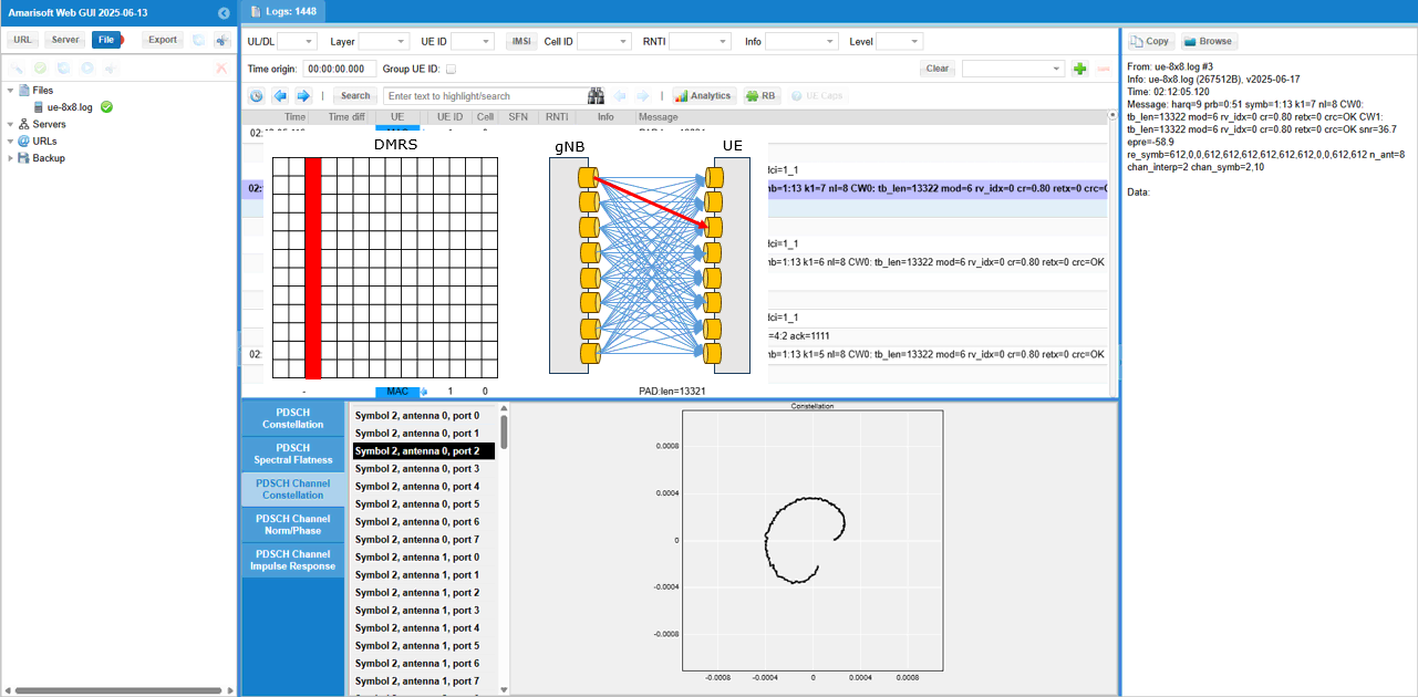
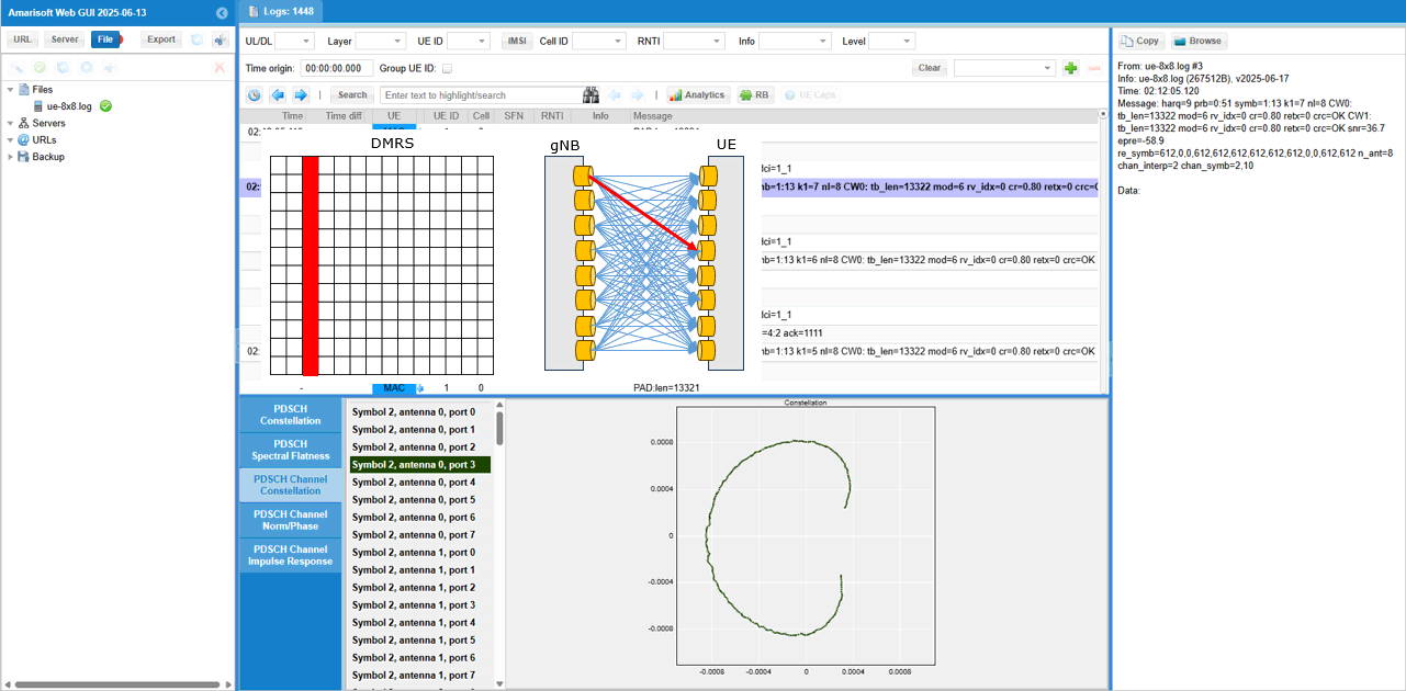
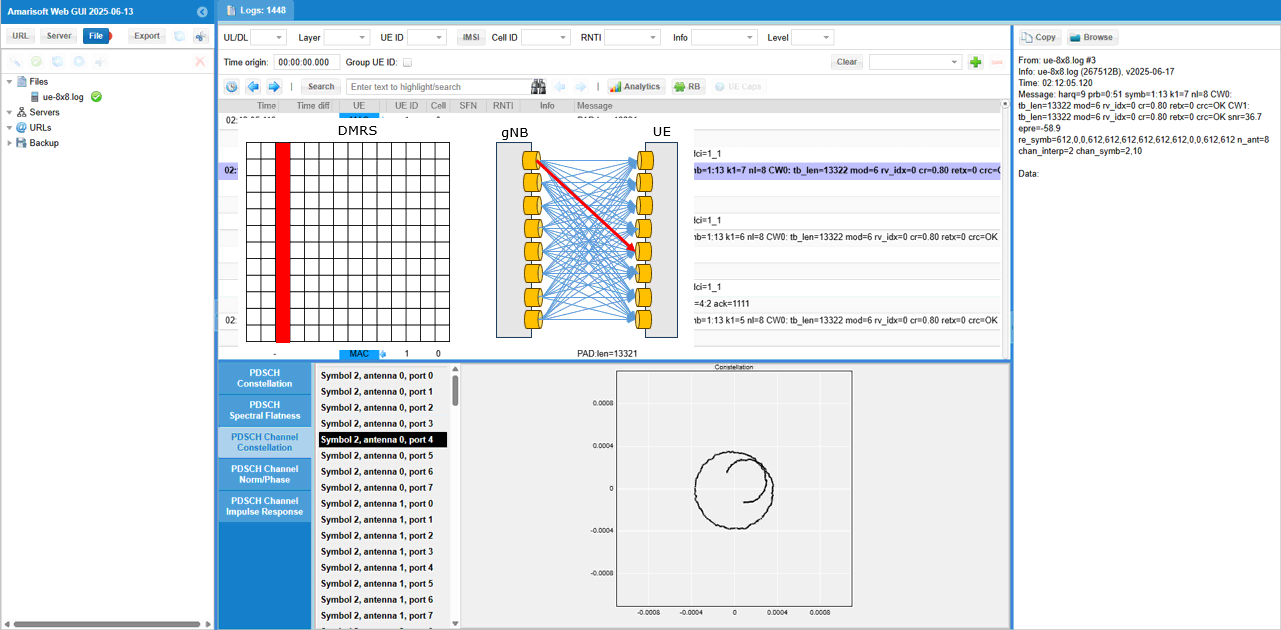
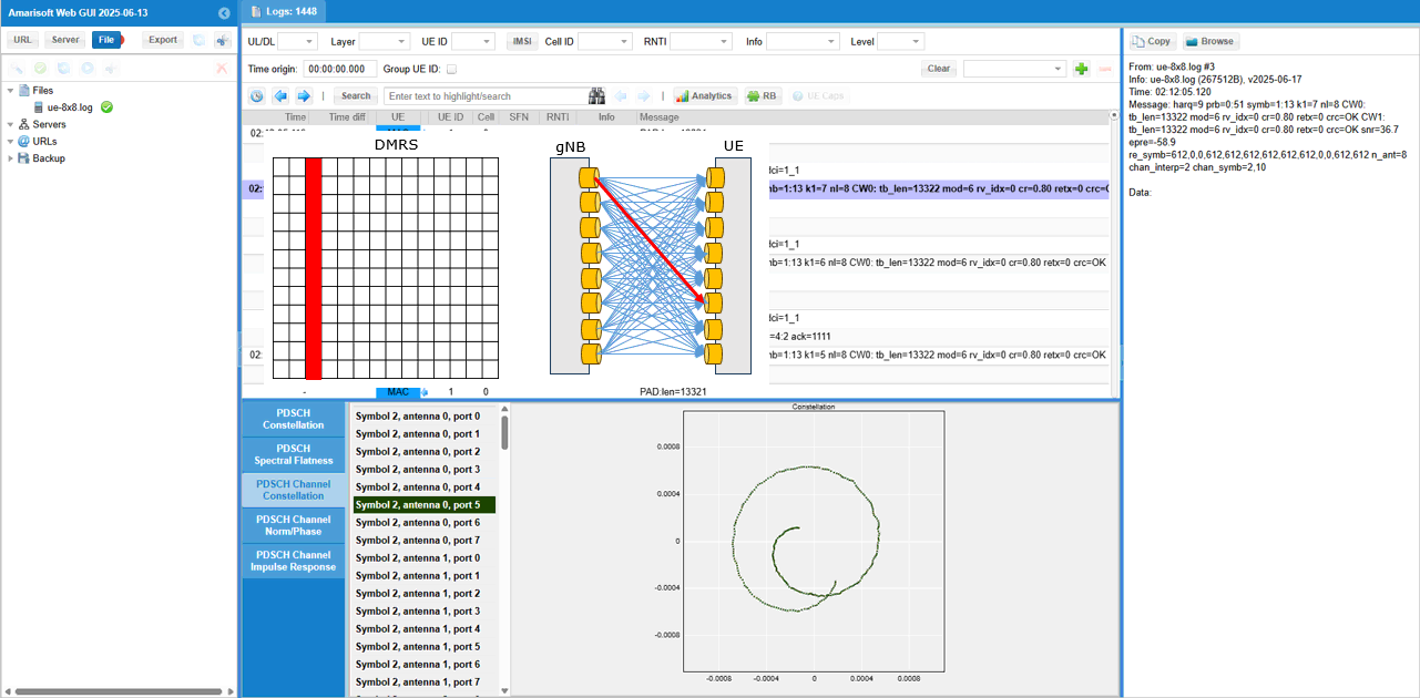
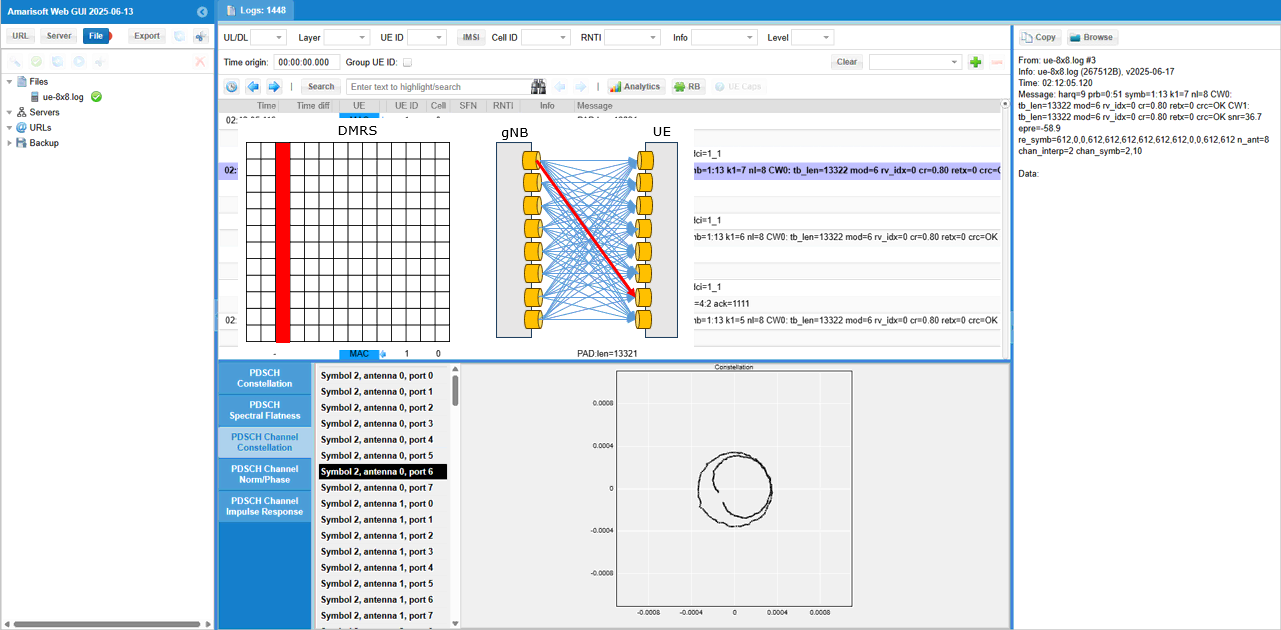
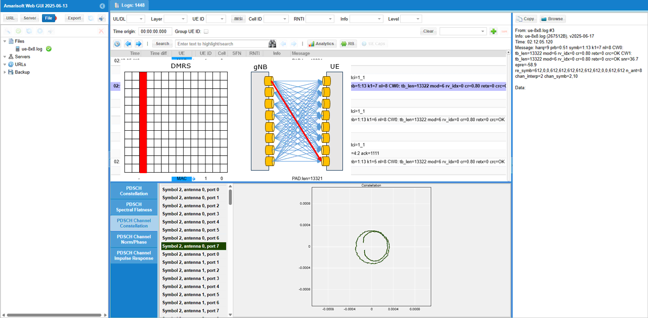
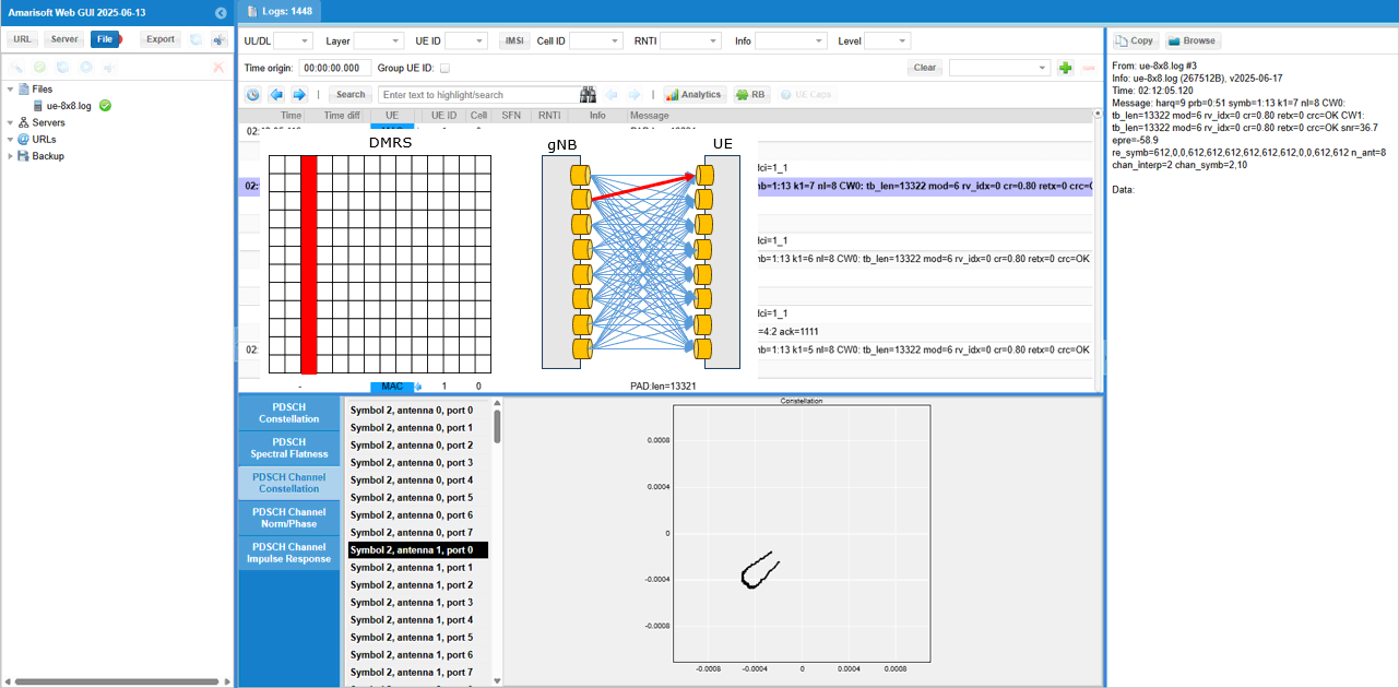
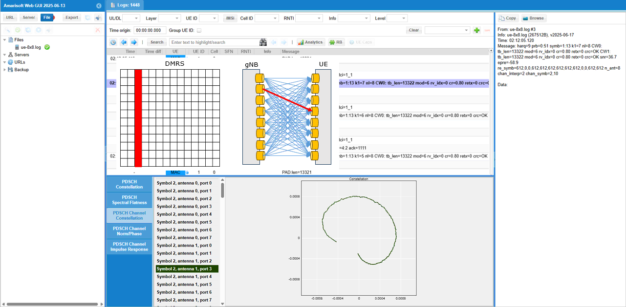
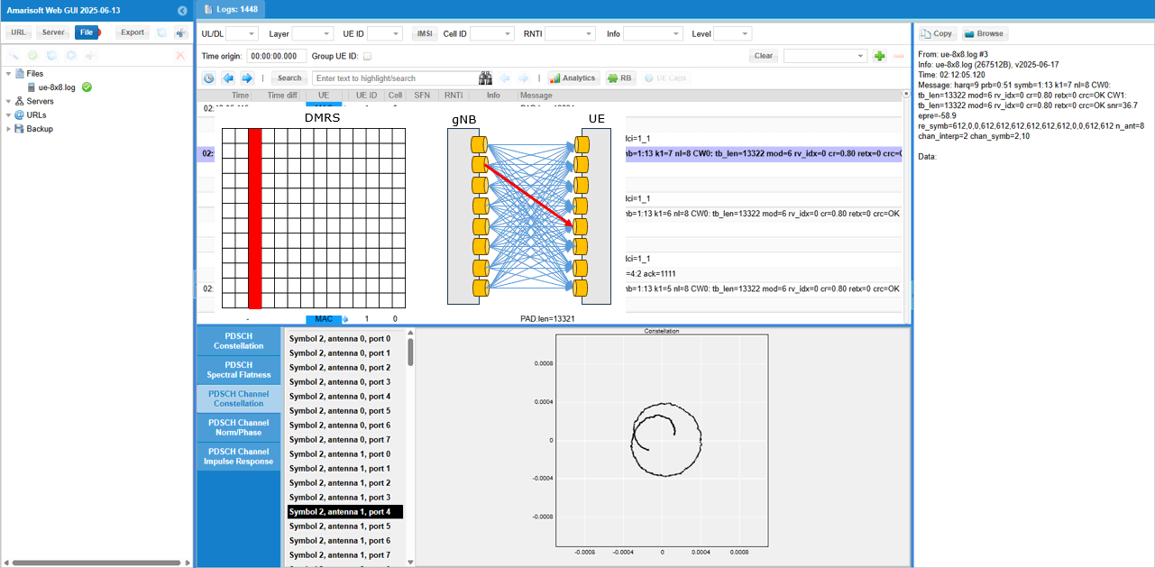
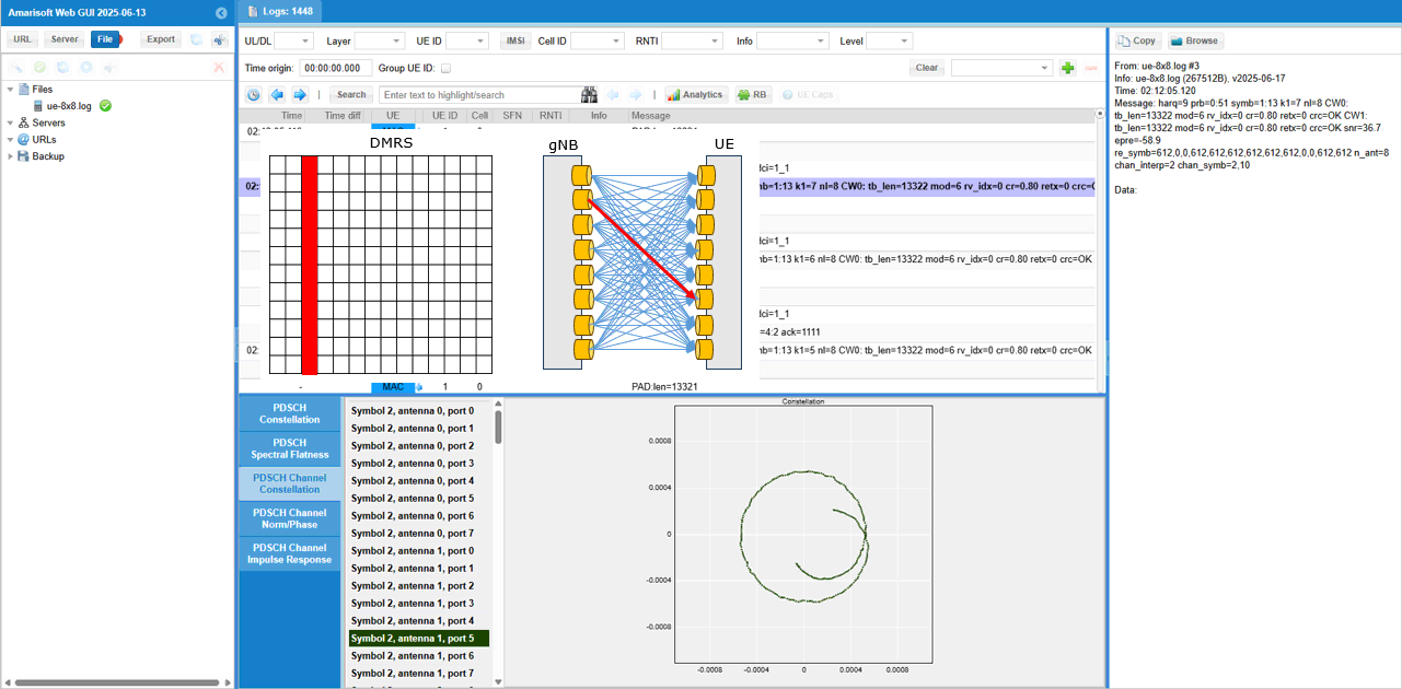
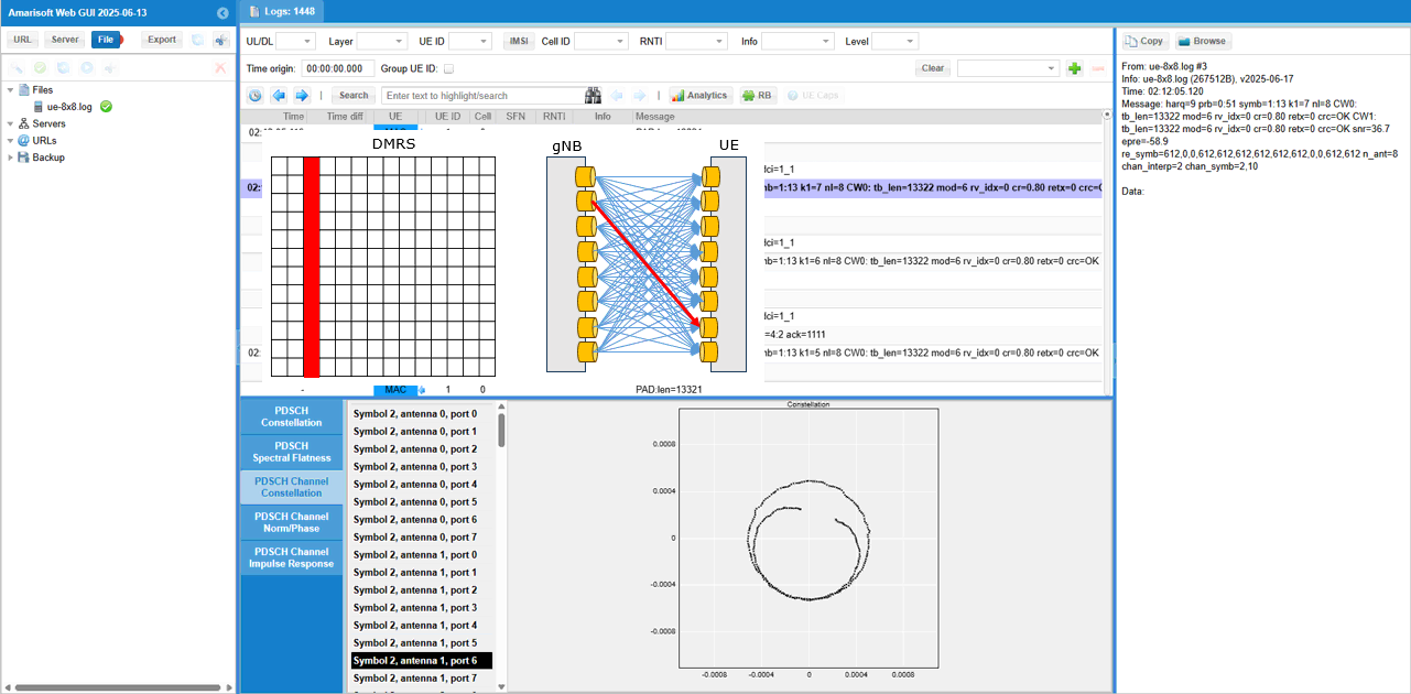
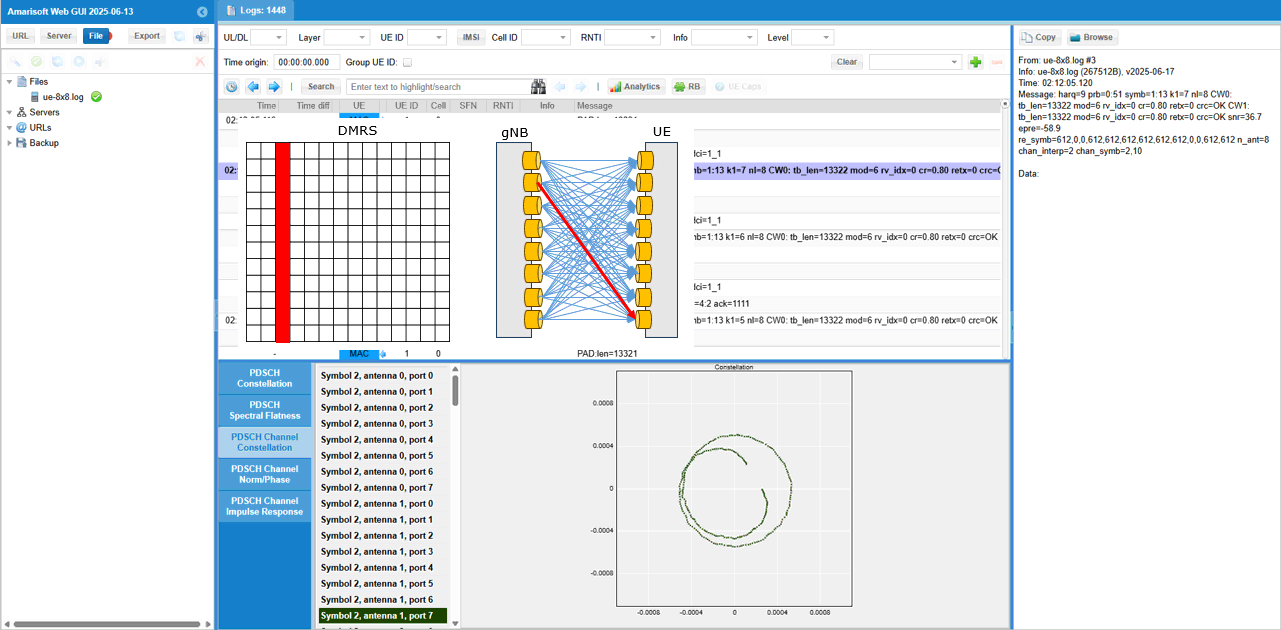
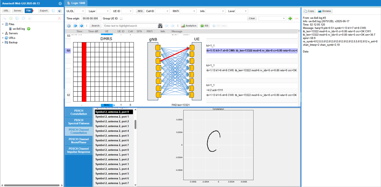
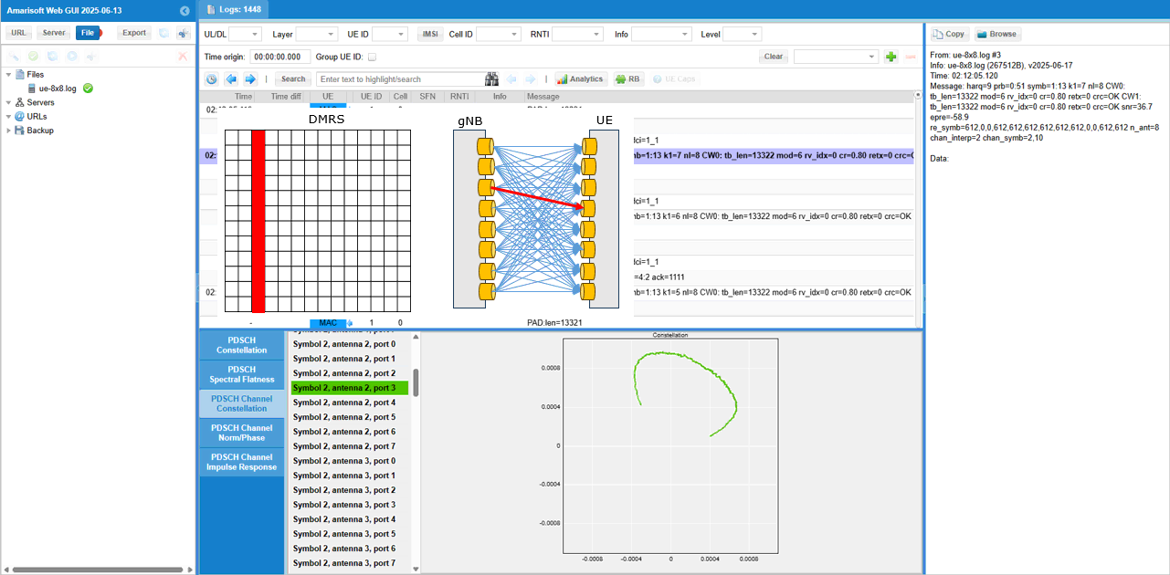
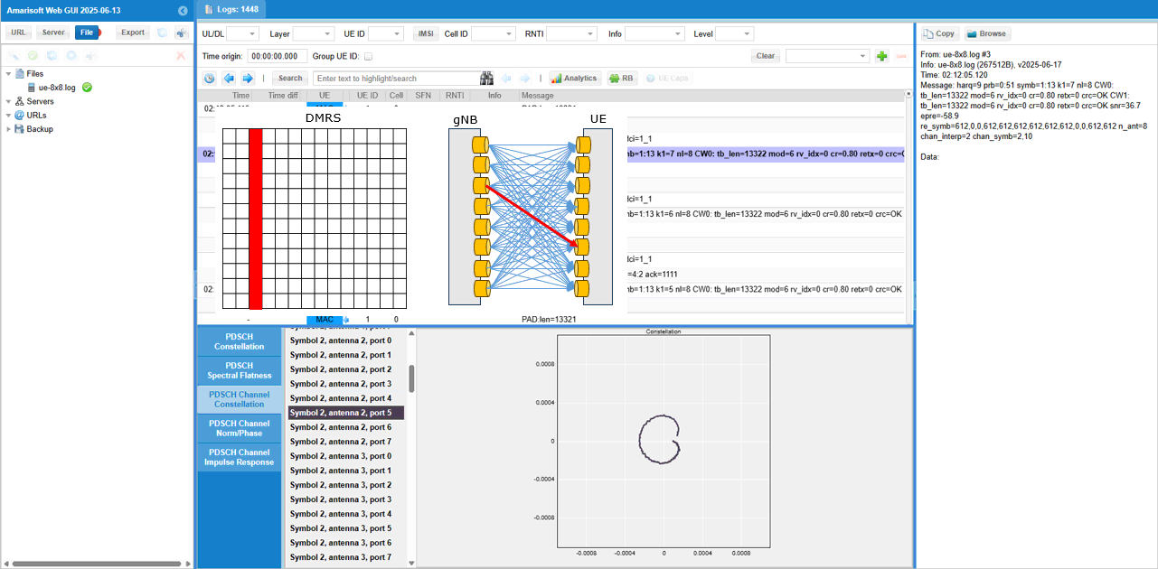
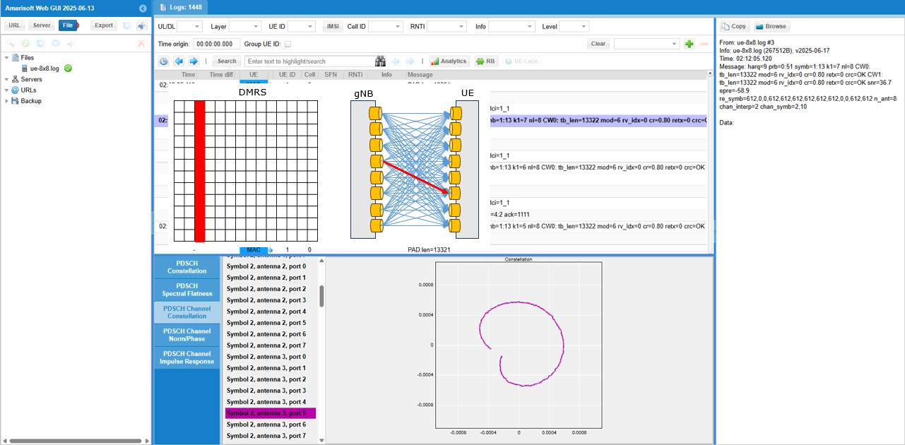
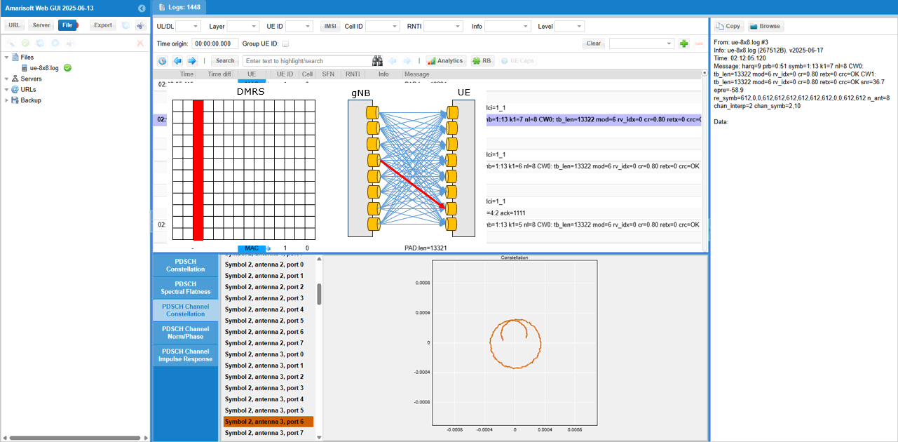
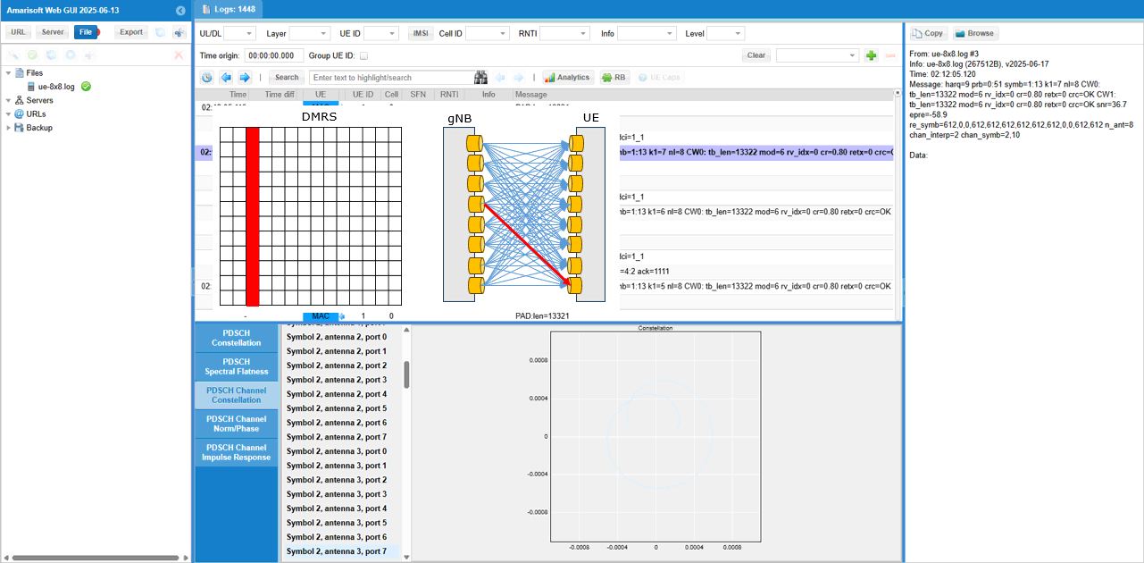
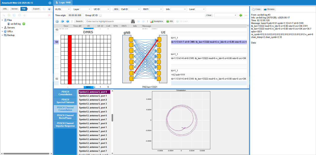
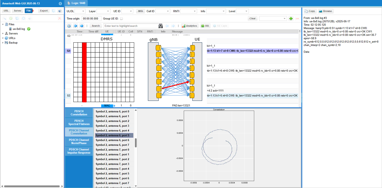
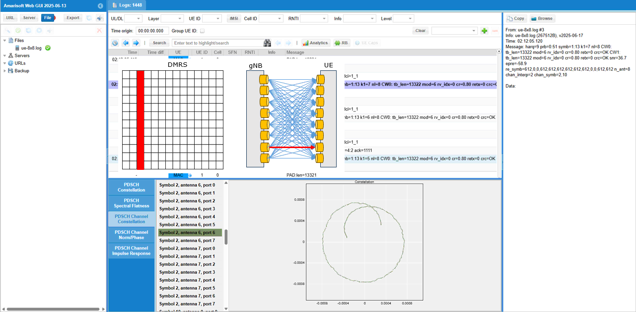
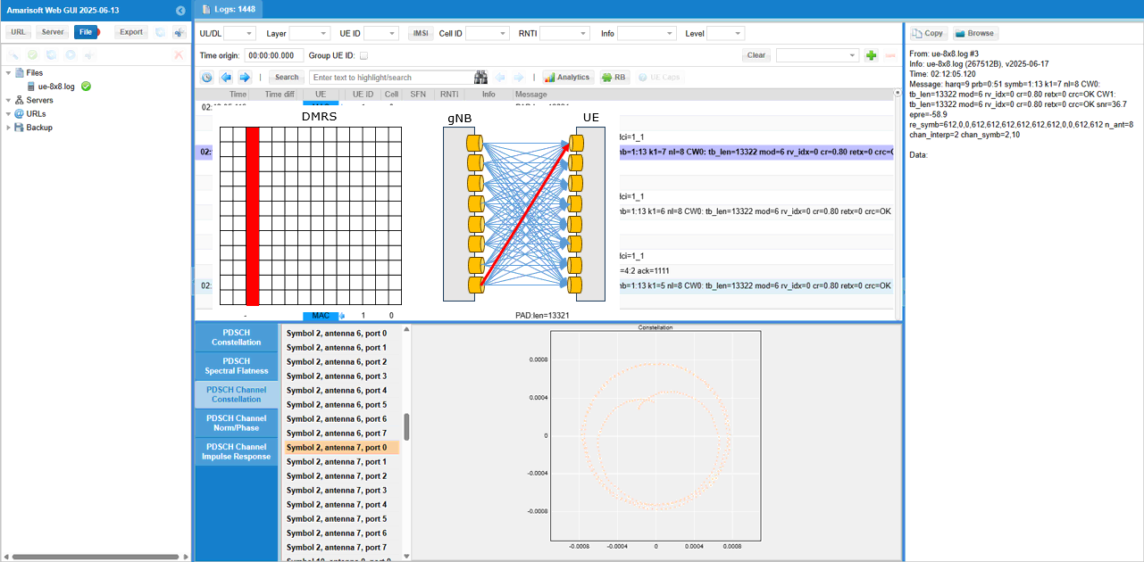
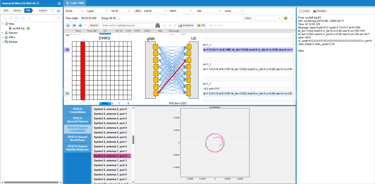
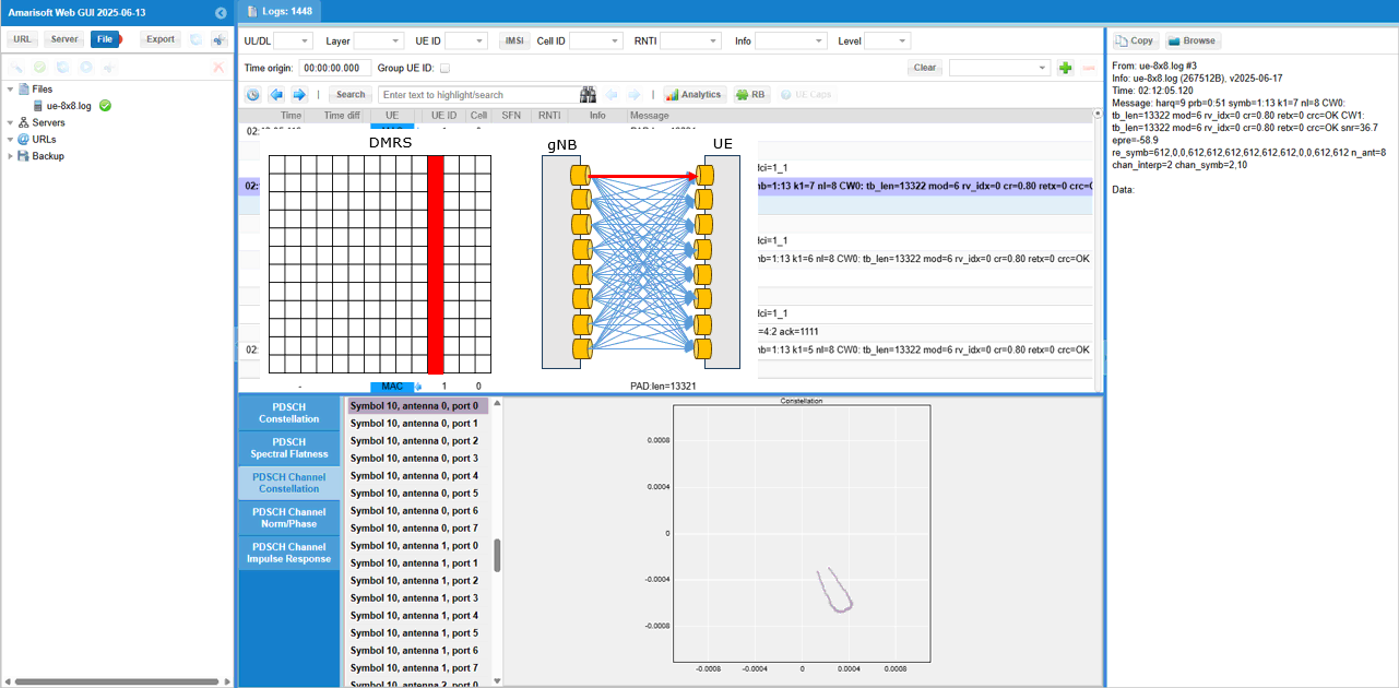
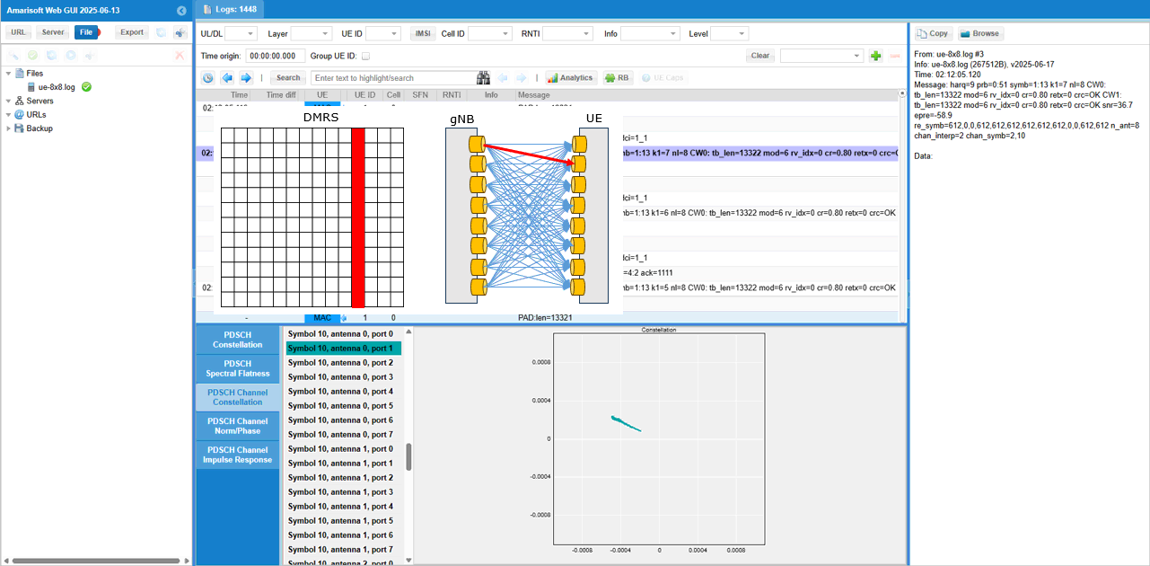
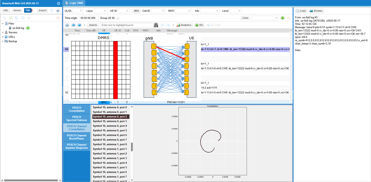
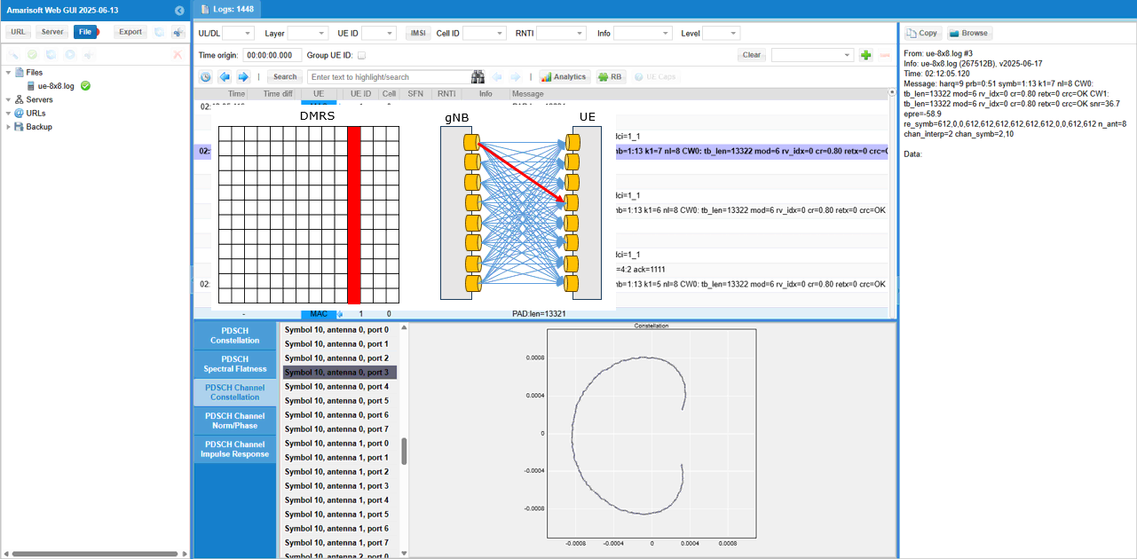
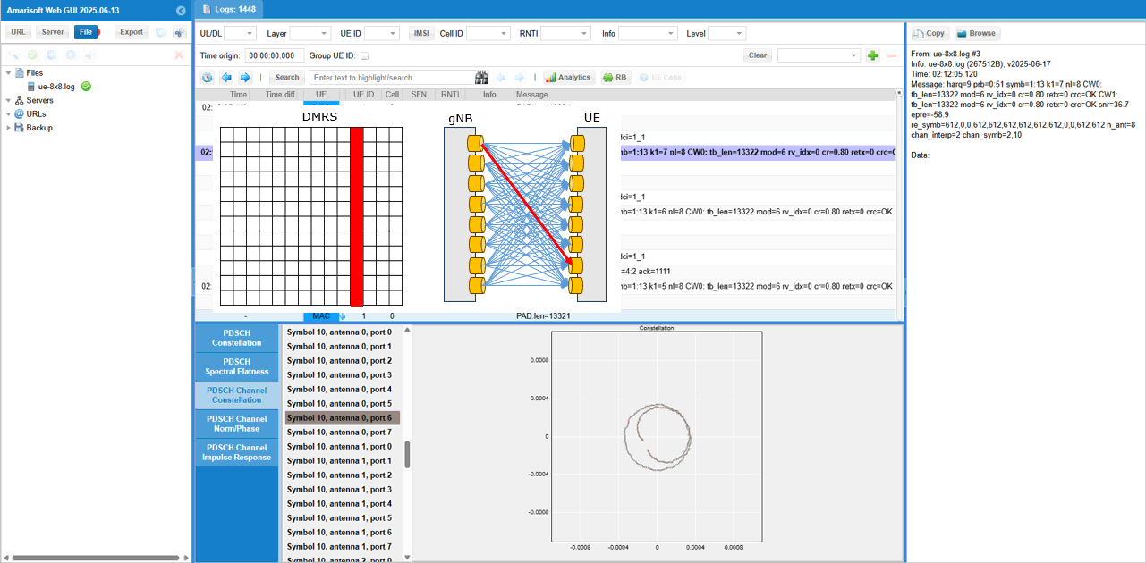
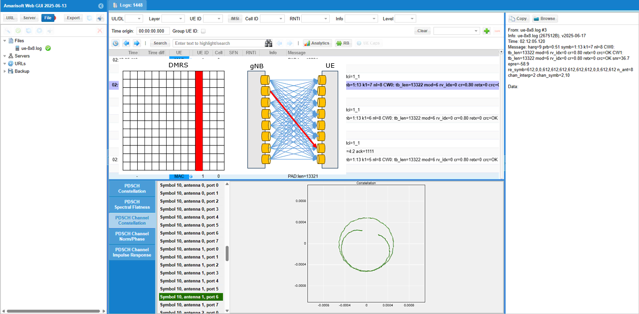
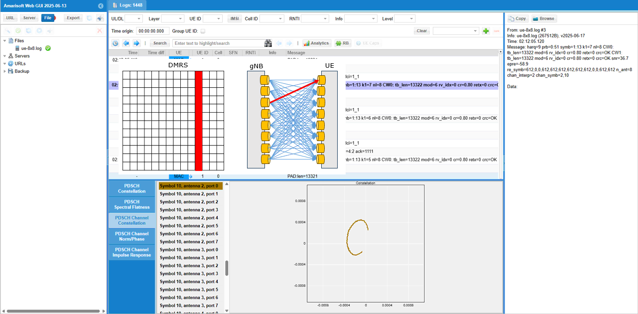
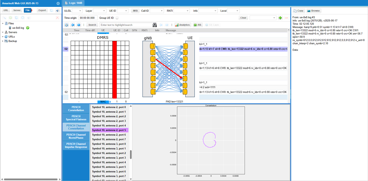
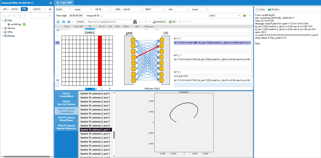
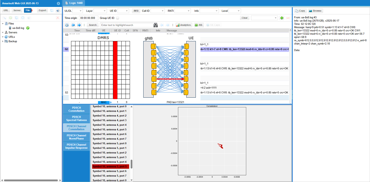
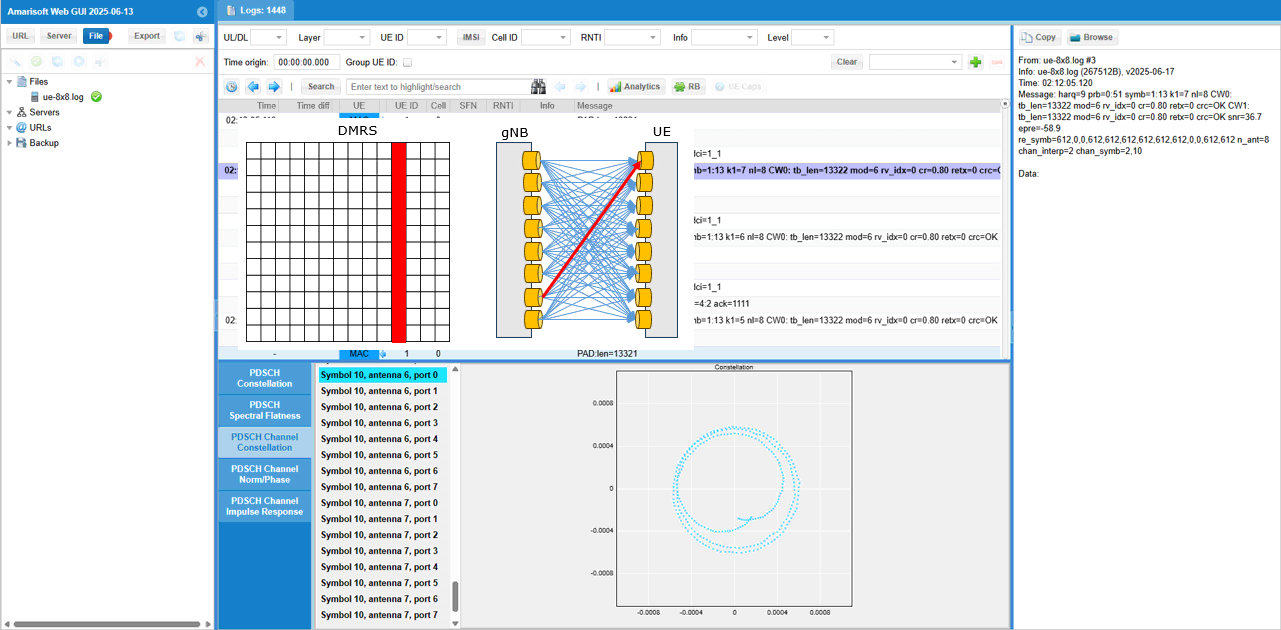
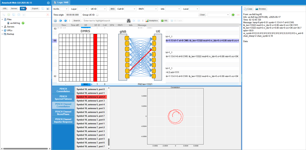
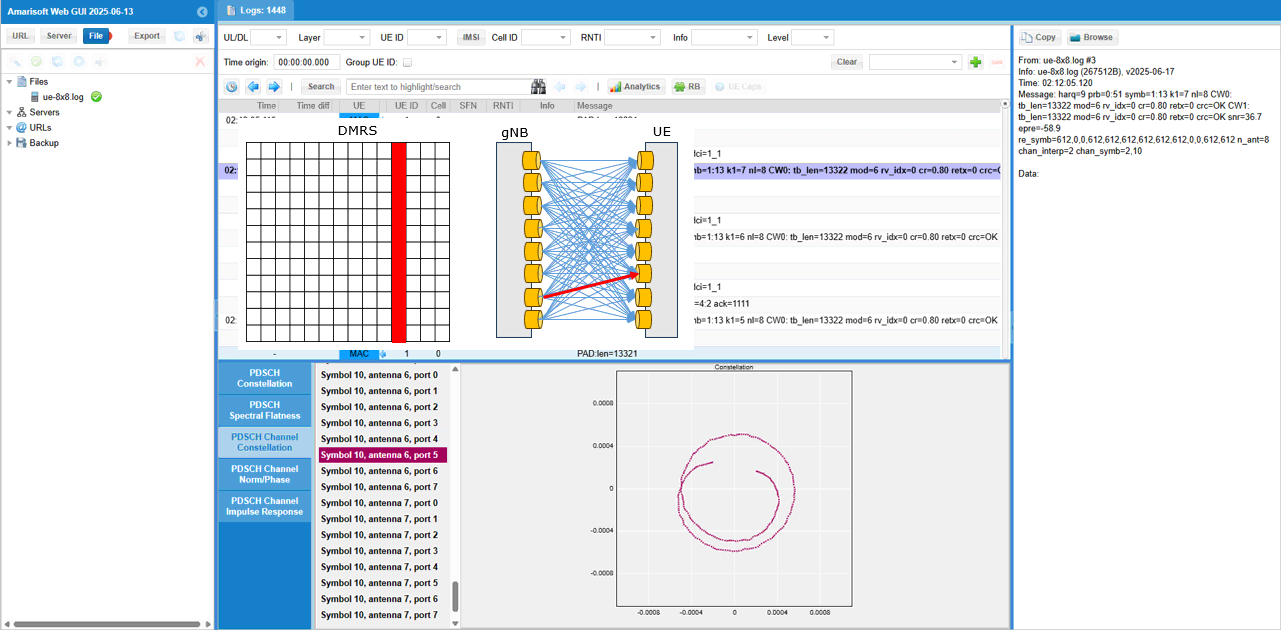
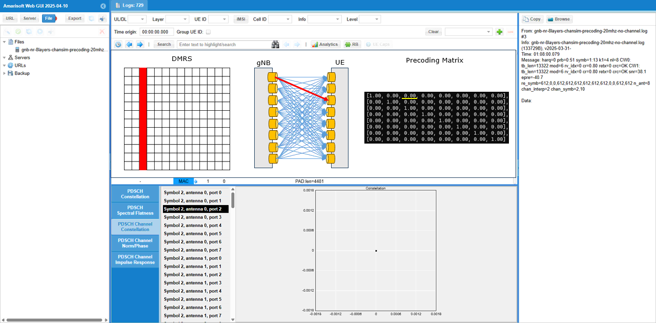
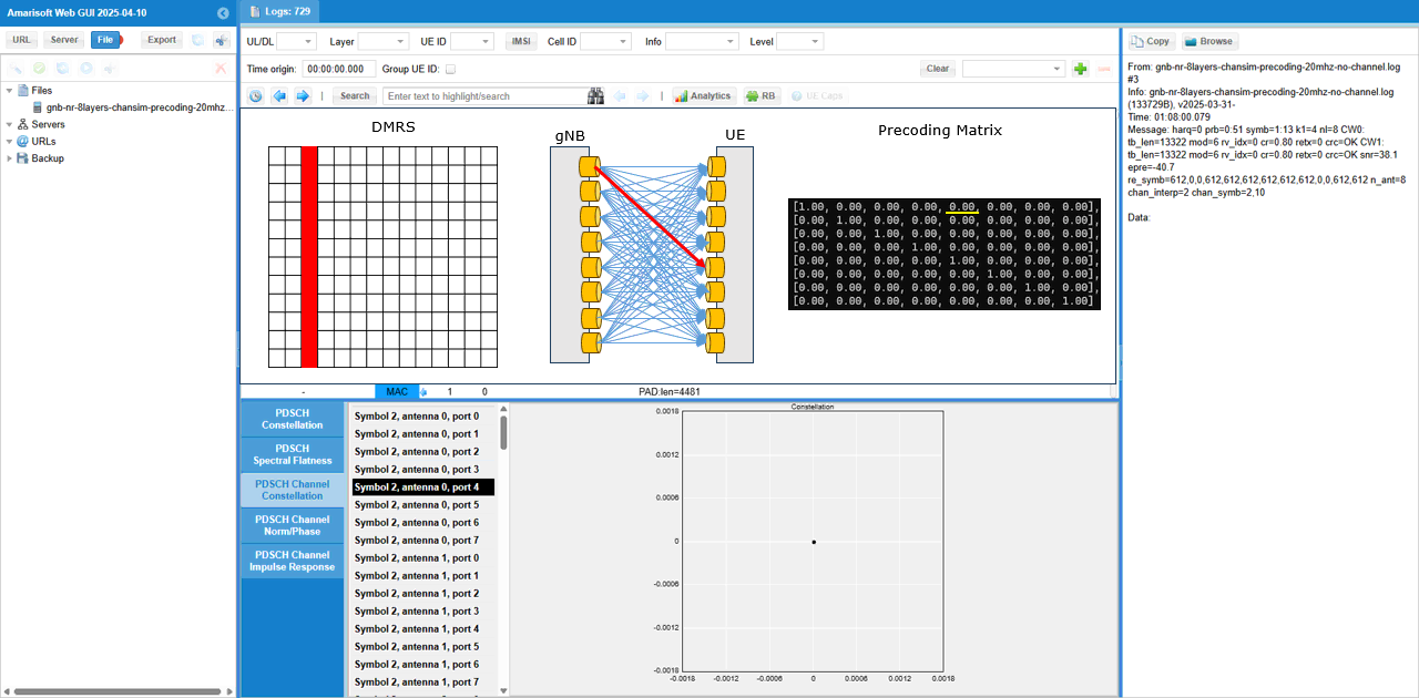
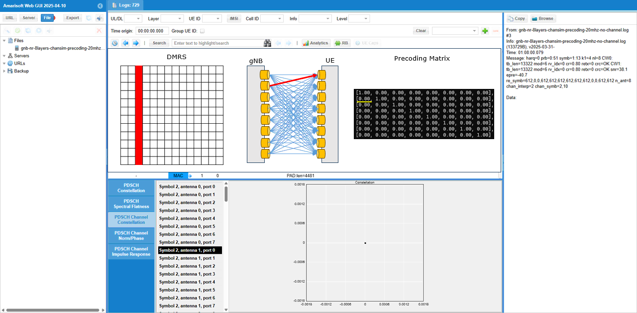
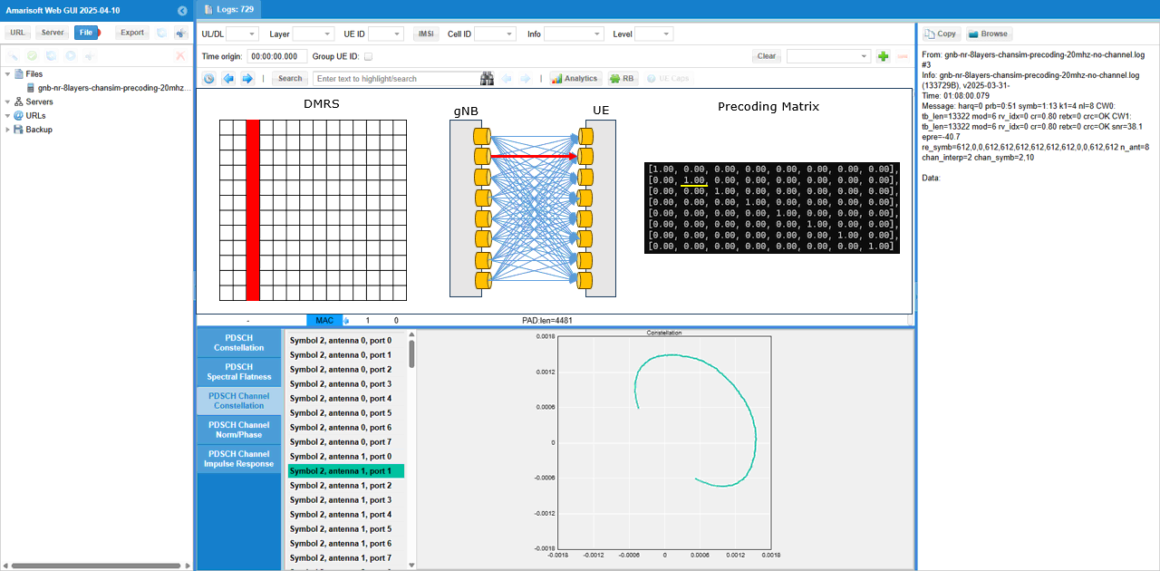
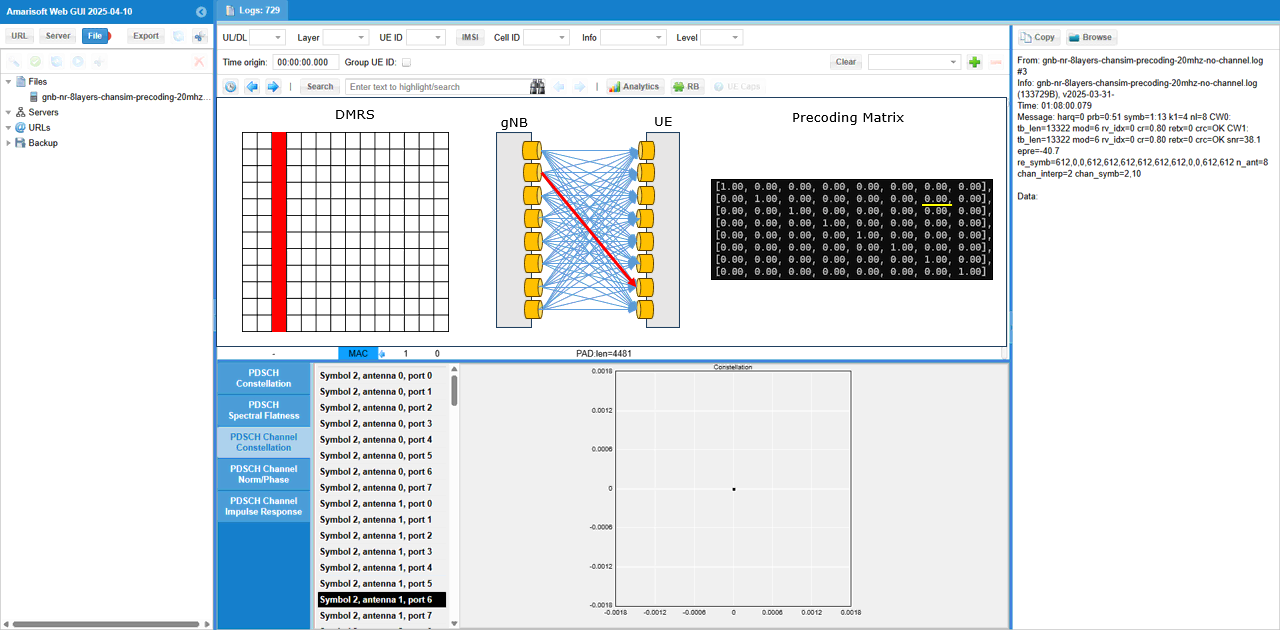
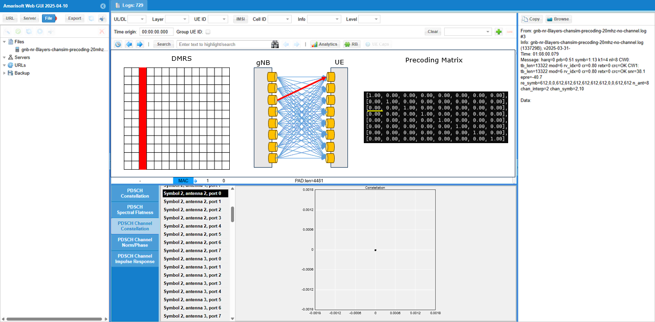
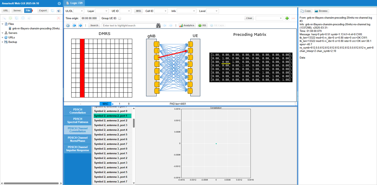
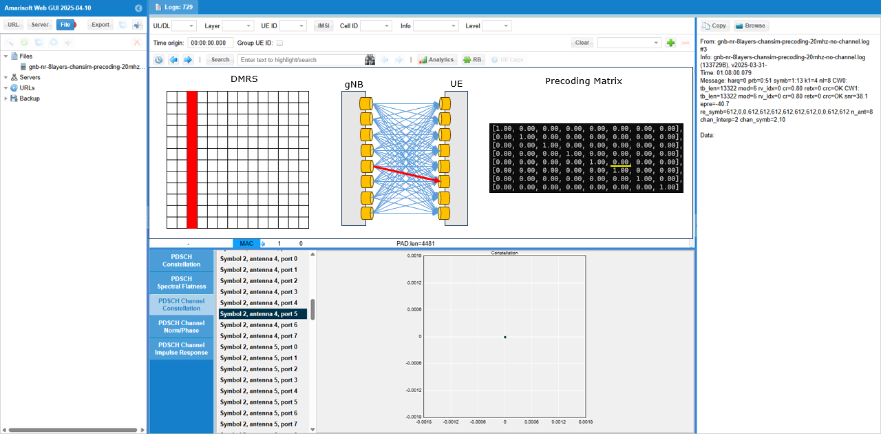
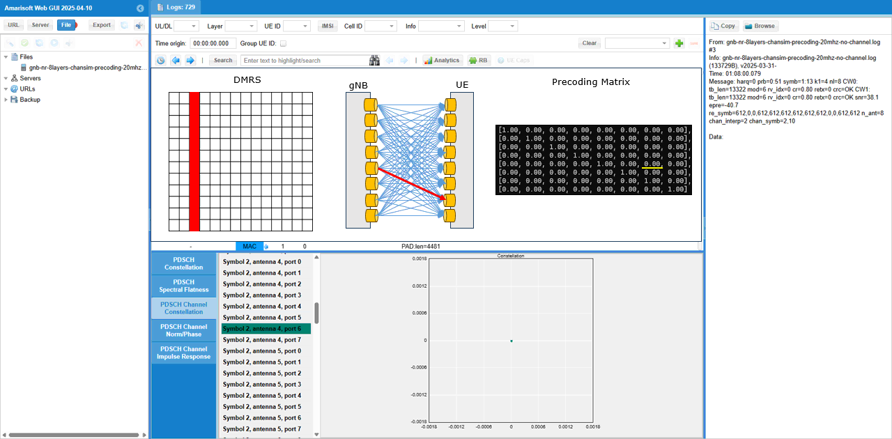
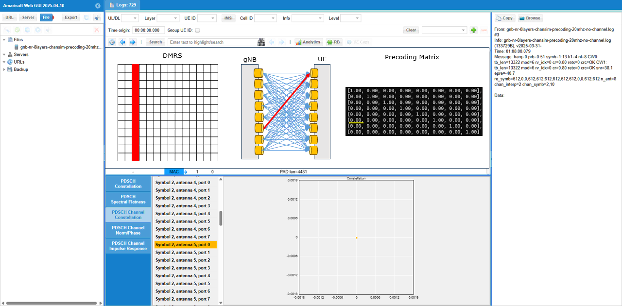
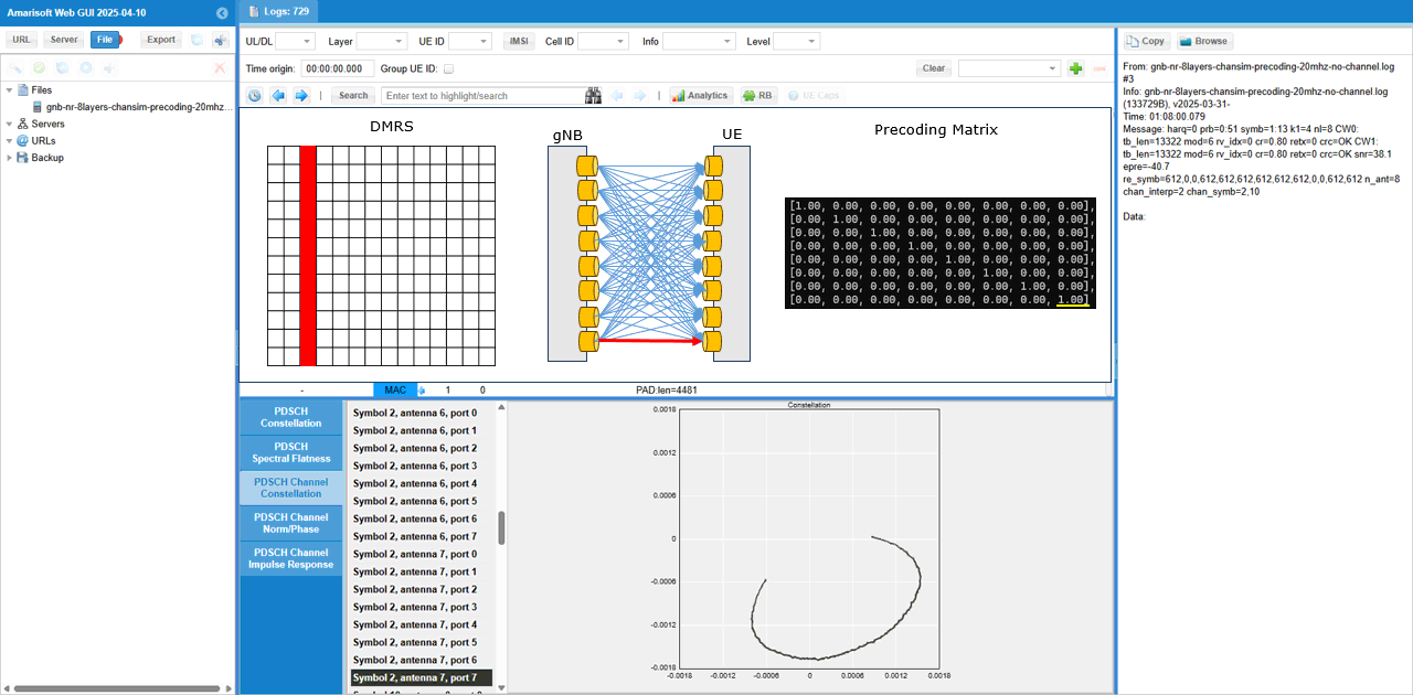
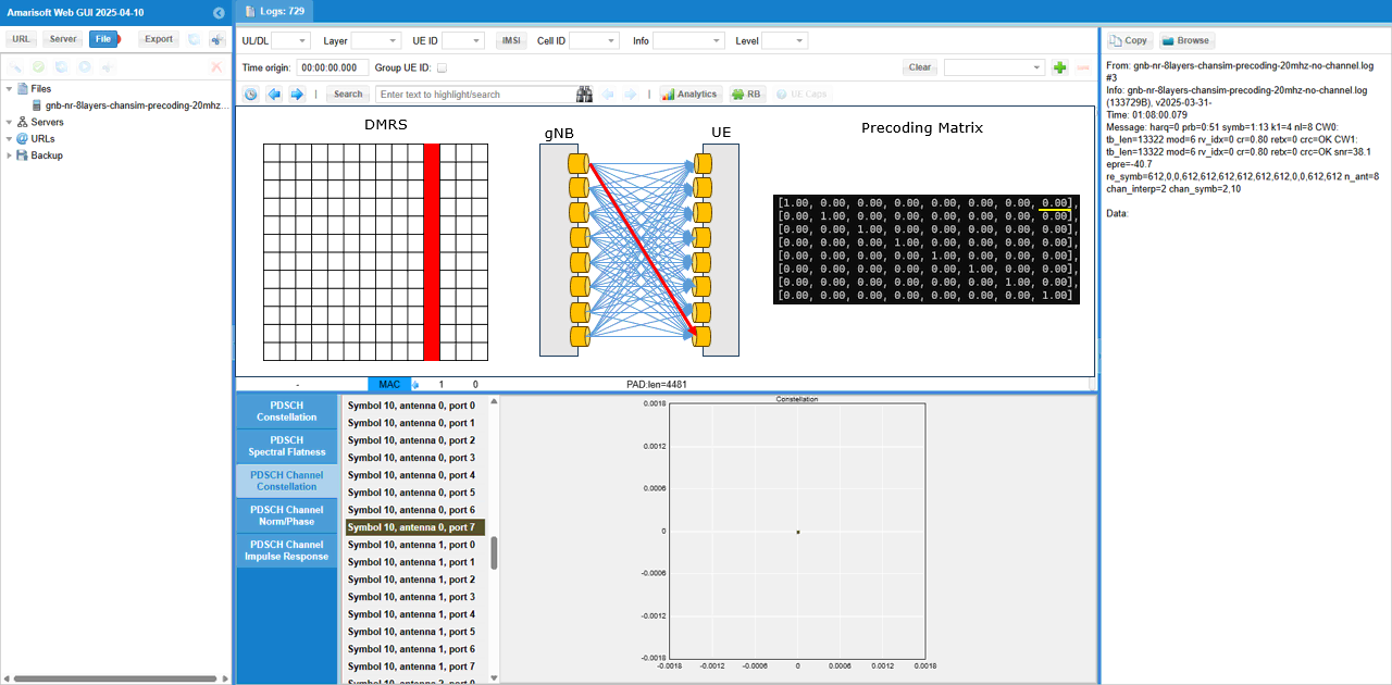
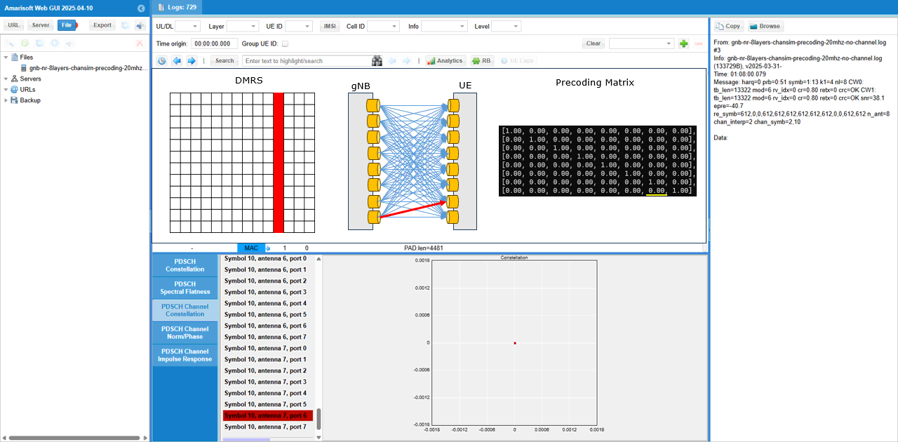
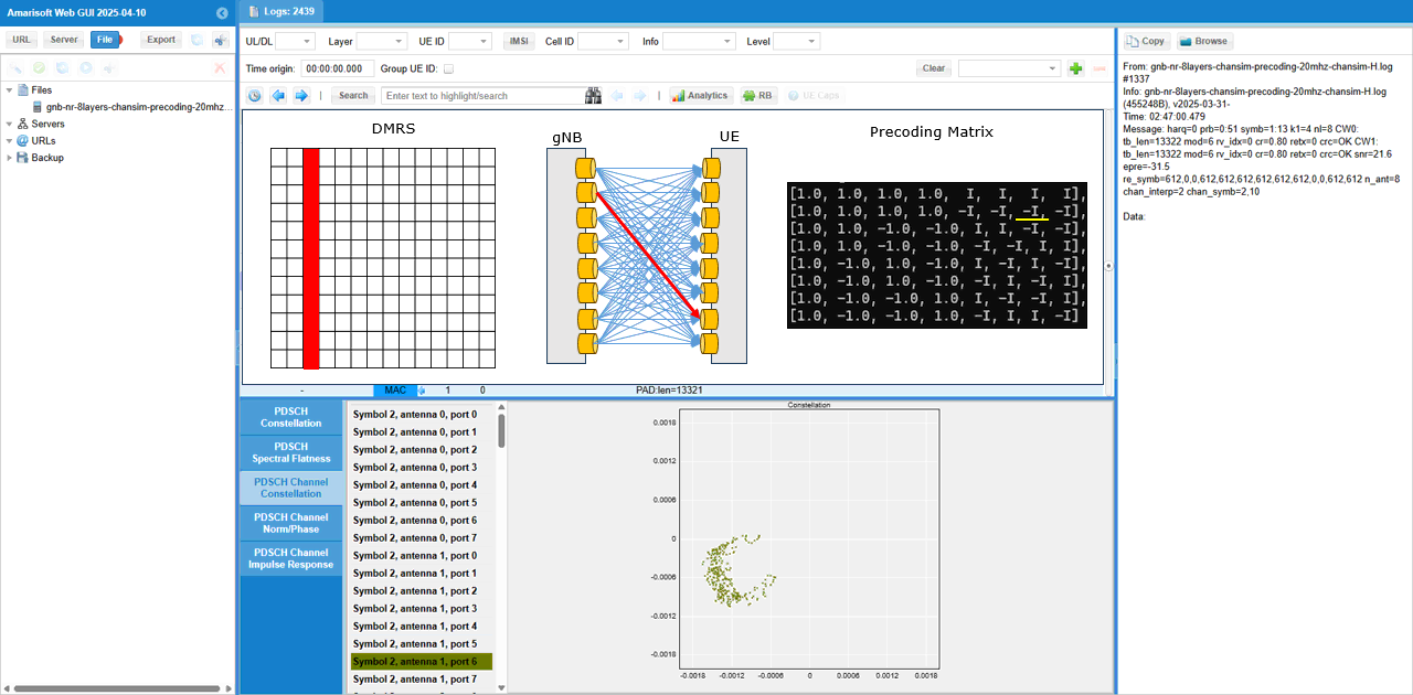
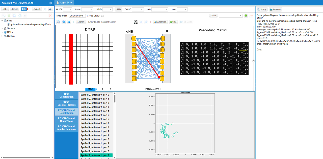
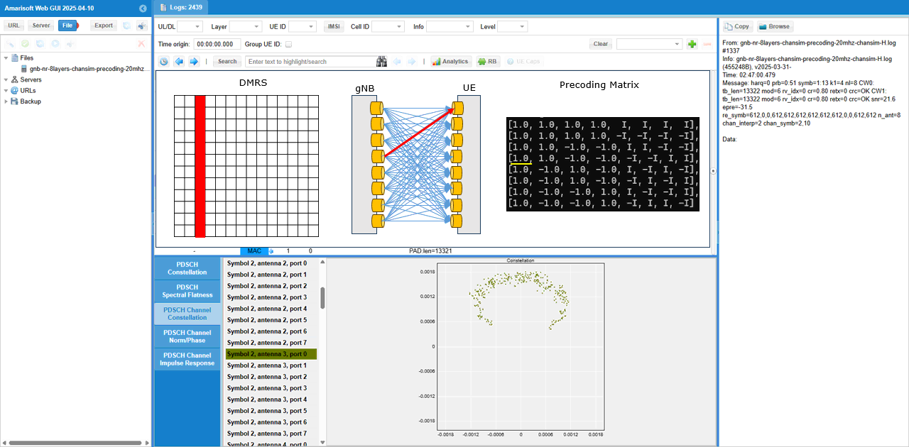
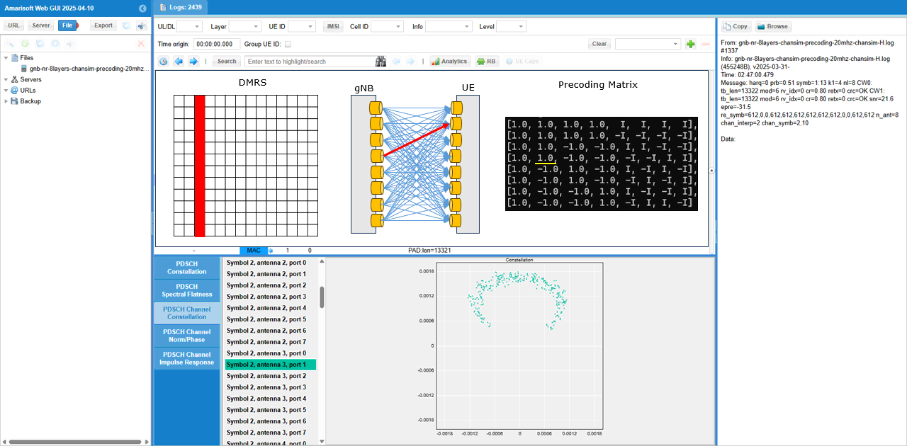
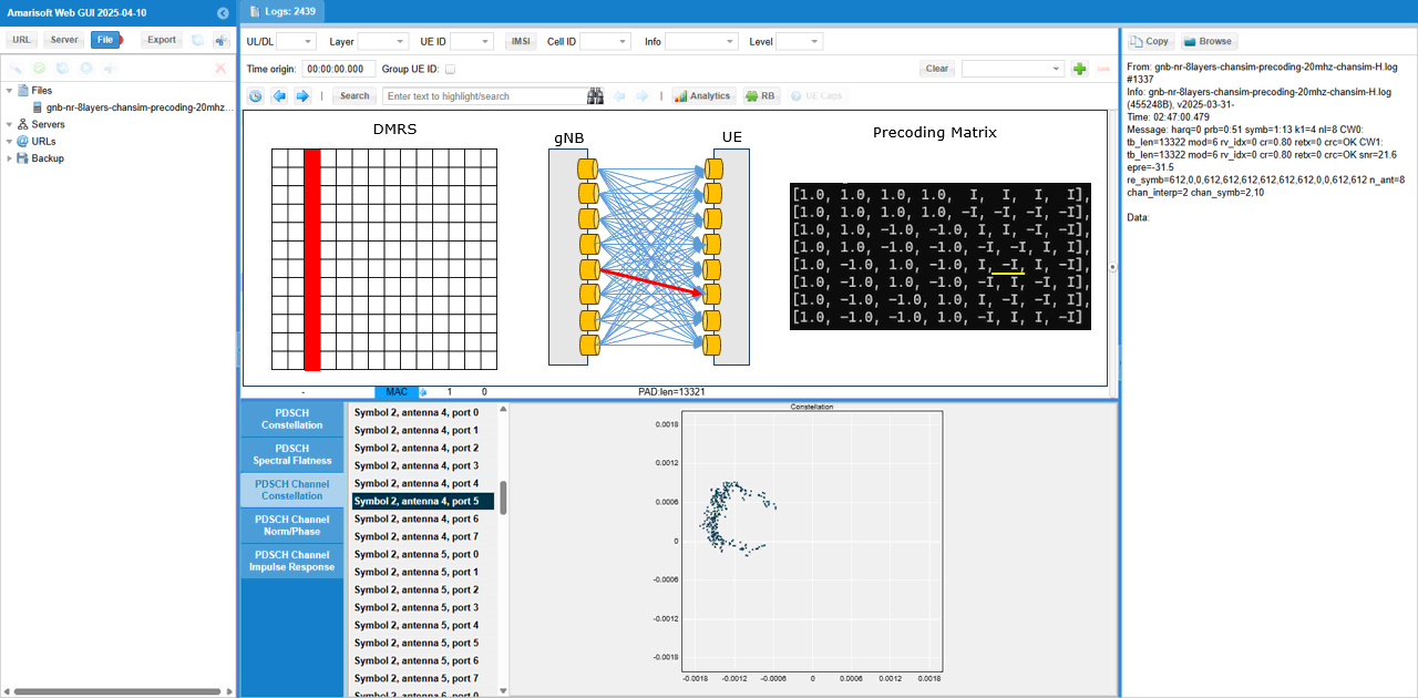
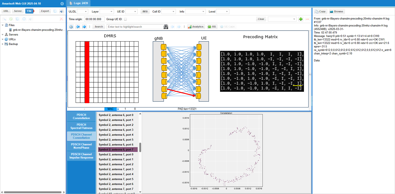
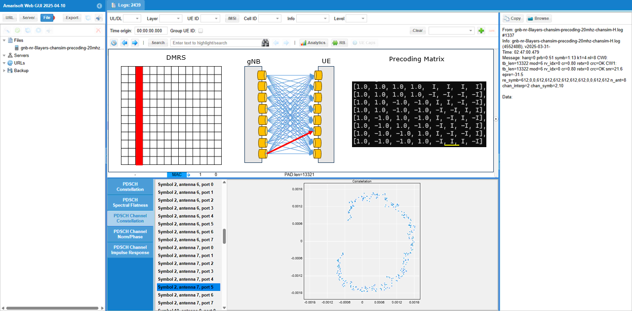
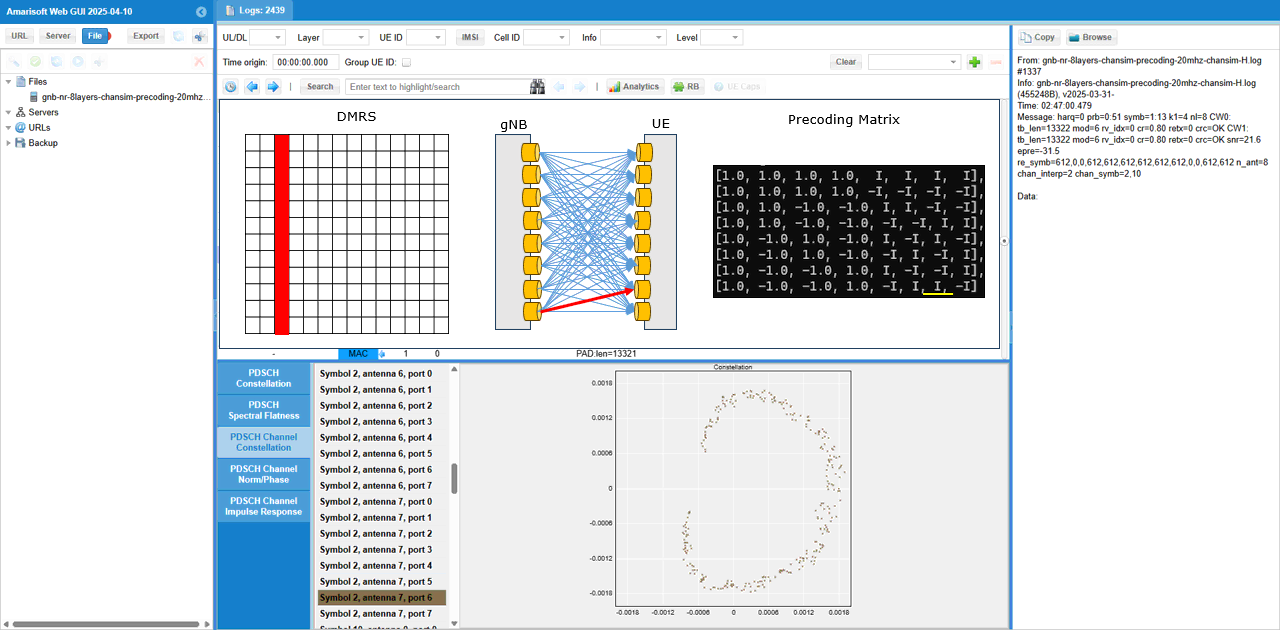
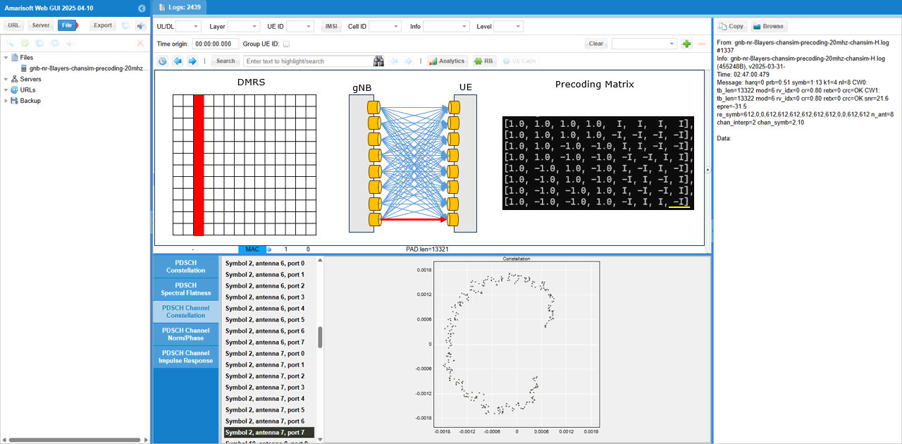
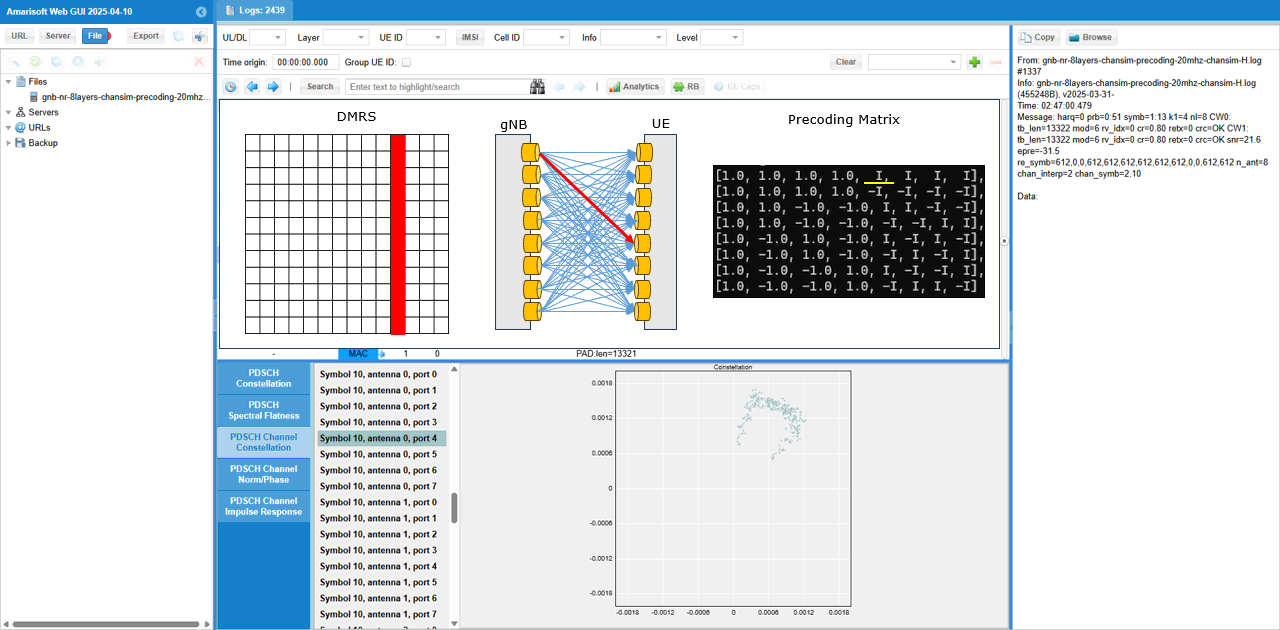
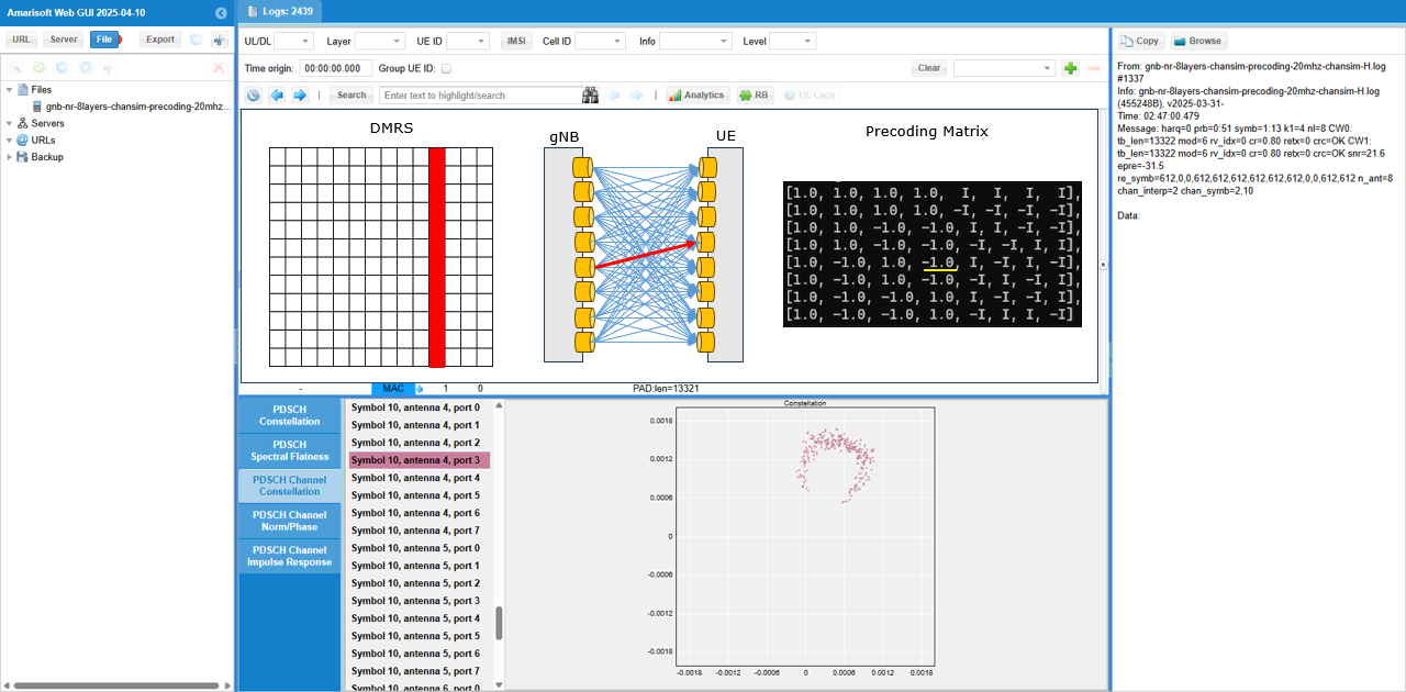
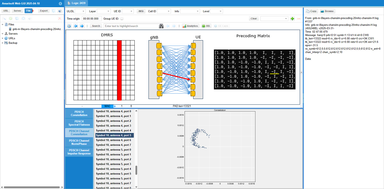
What I am intended to show in this test is this plot. This shows the channel coefficent for each & every DMRS RE (Resource Element) of the PDSCH between every TX antenna and every RX antenna. From this plot, it is not clear on how a specific channel from a specific Tx to a specific Rx antenna look like.
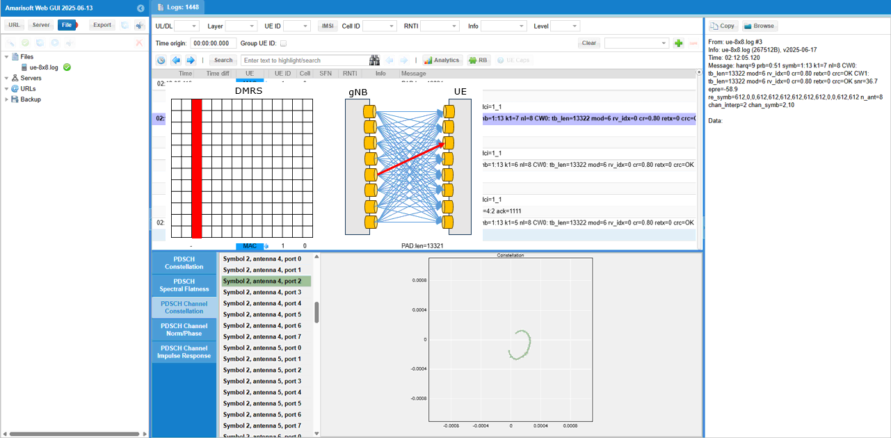
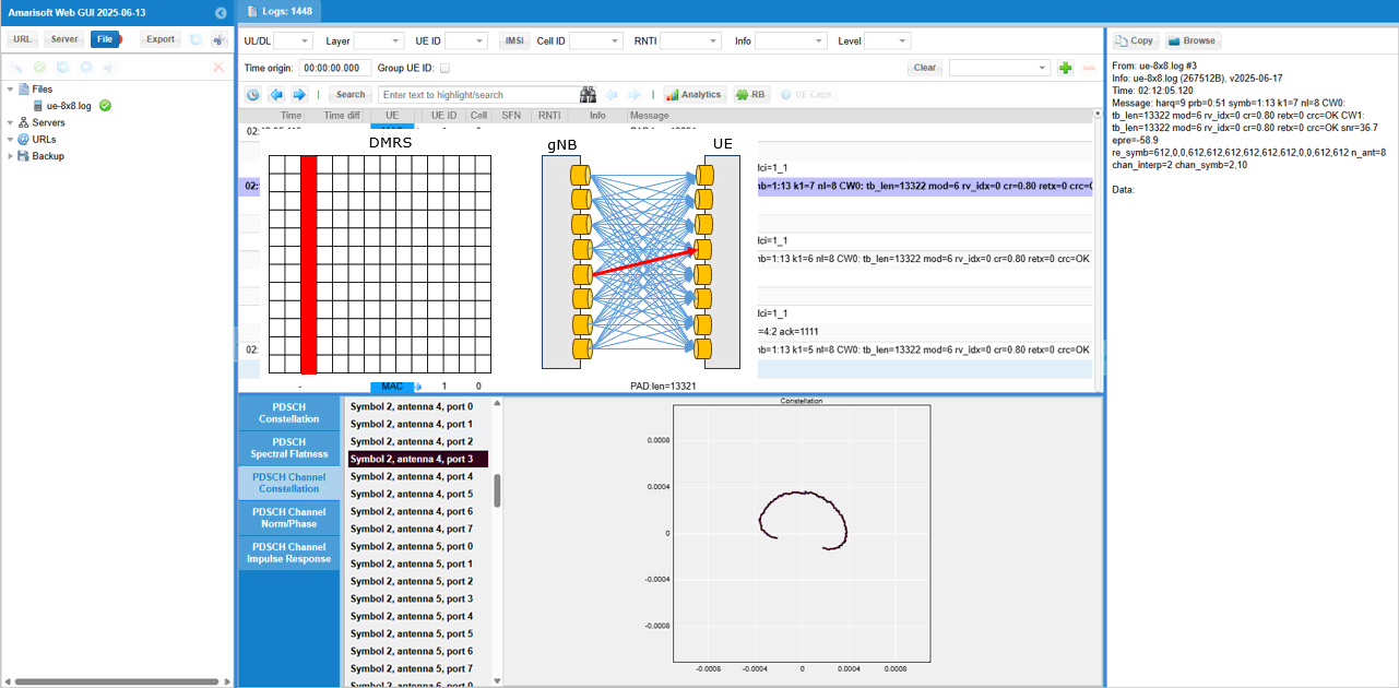
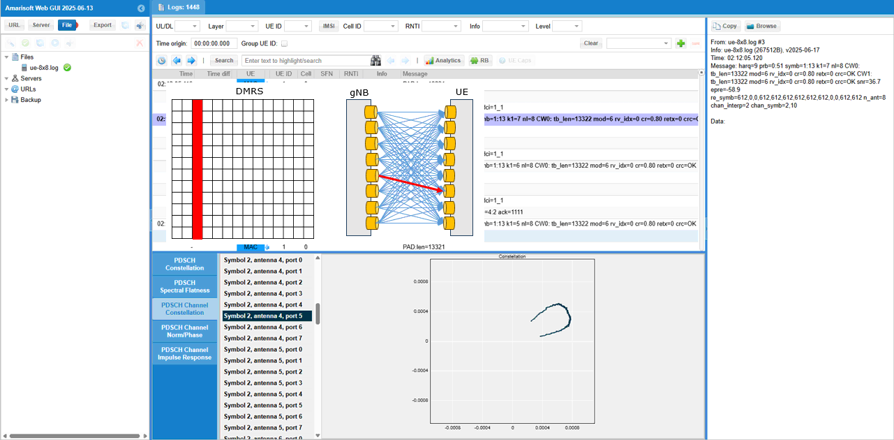
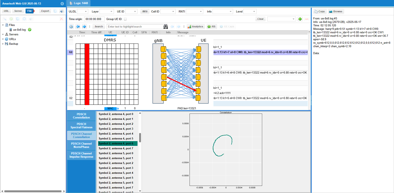
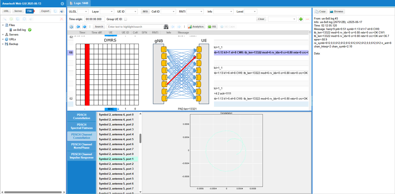
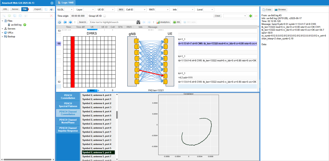
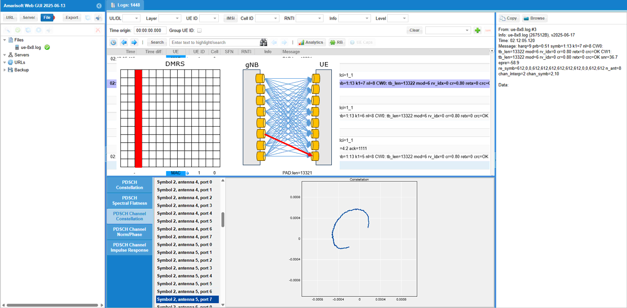
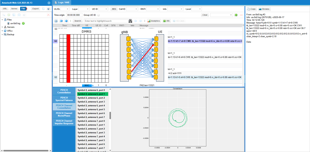
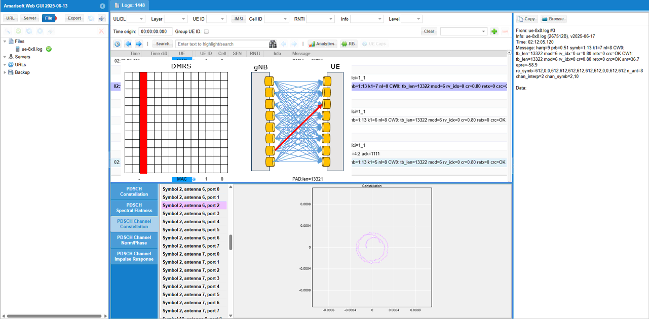
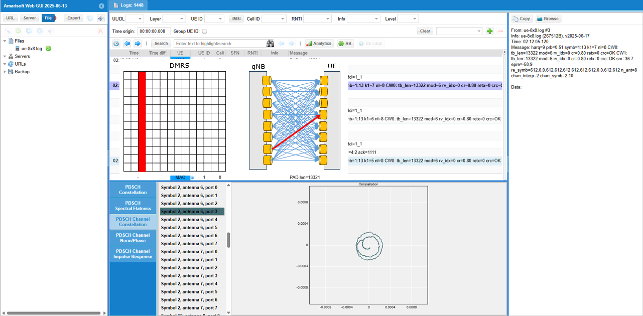
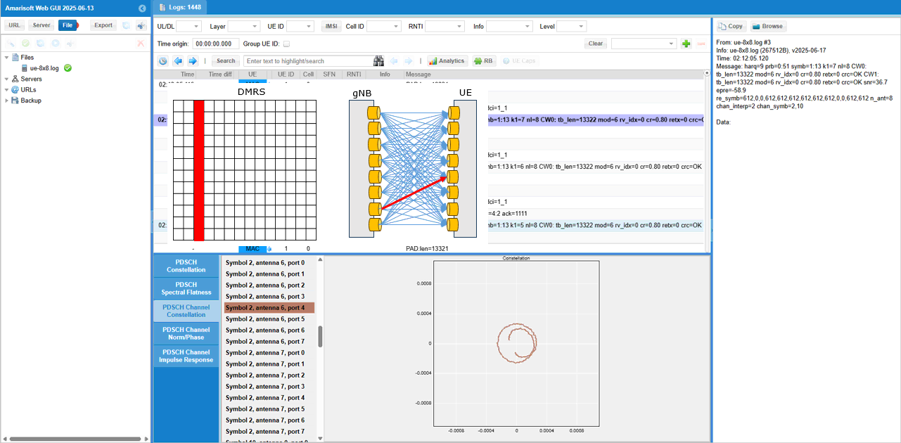
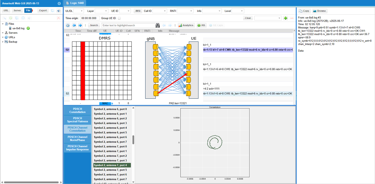
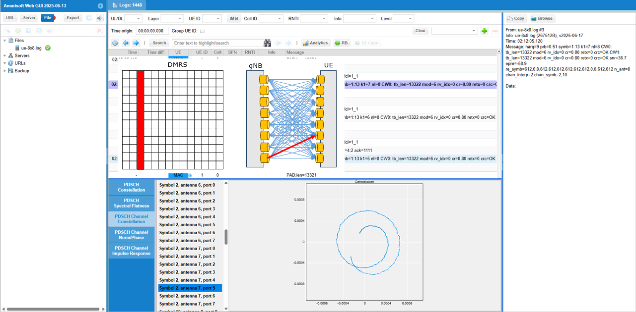
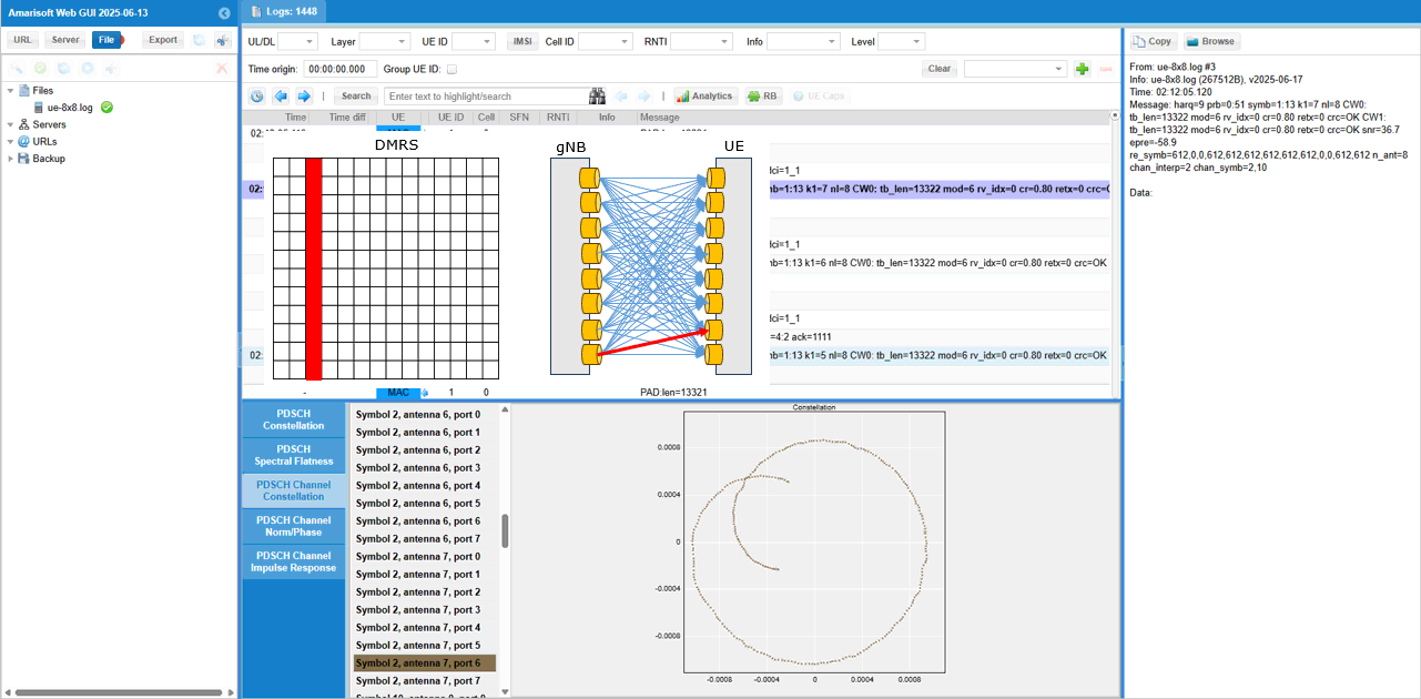
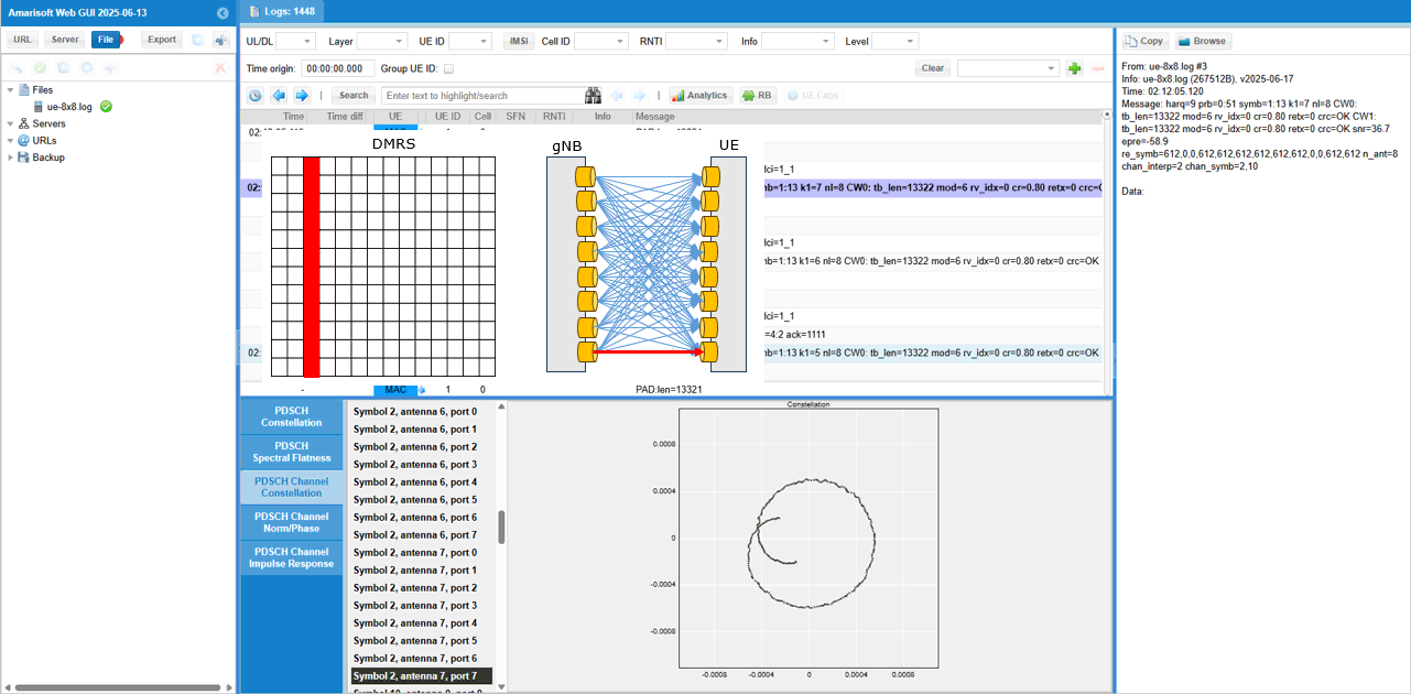
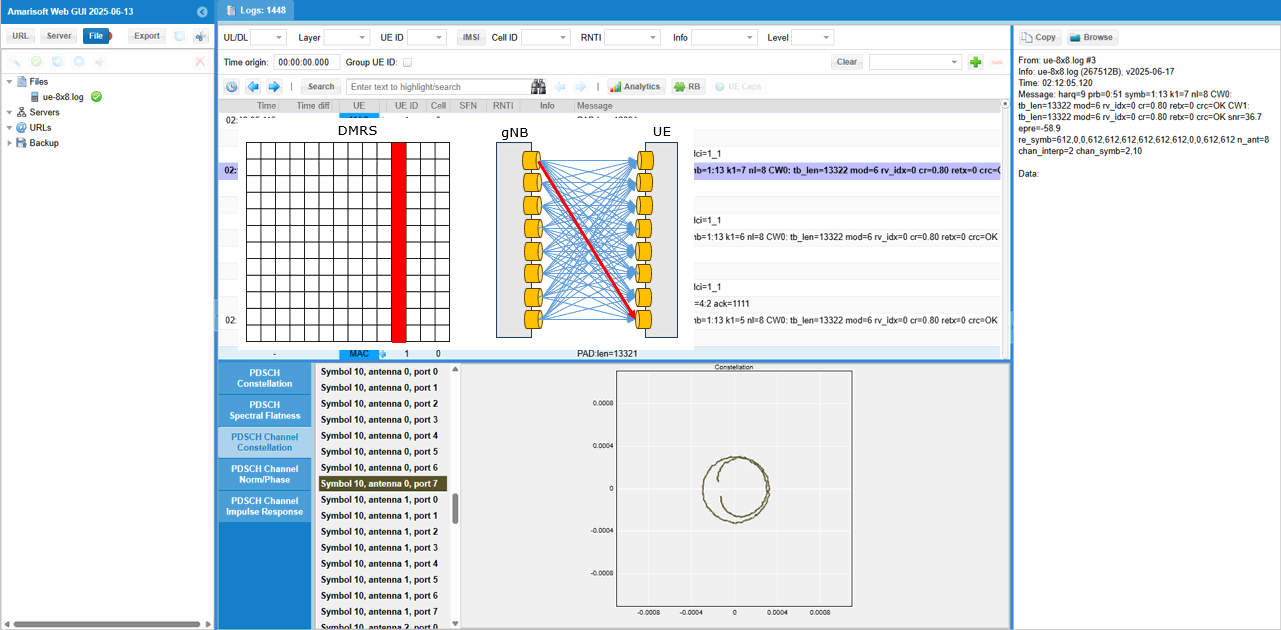
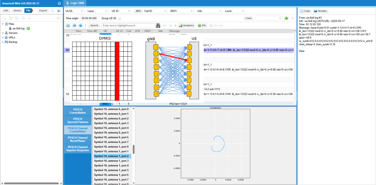
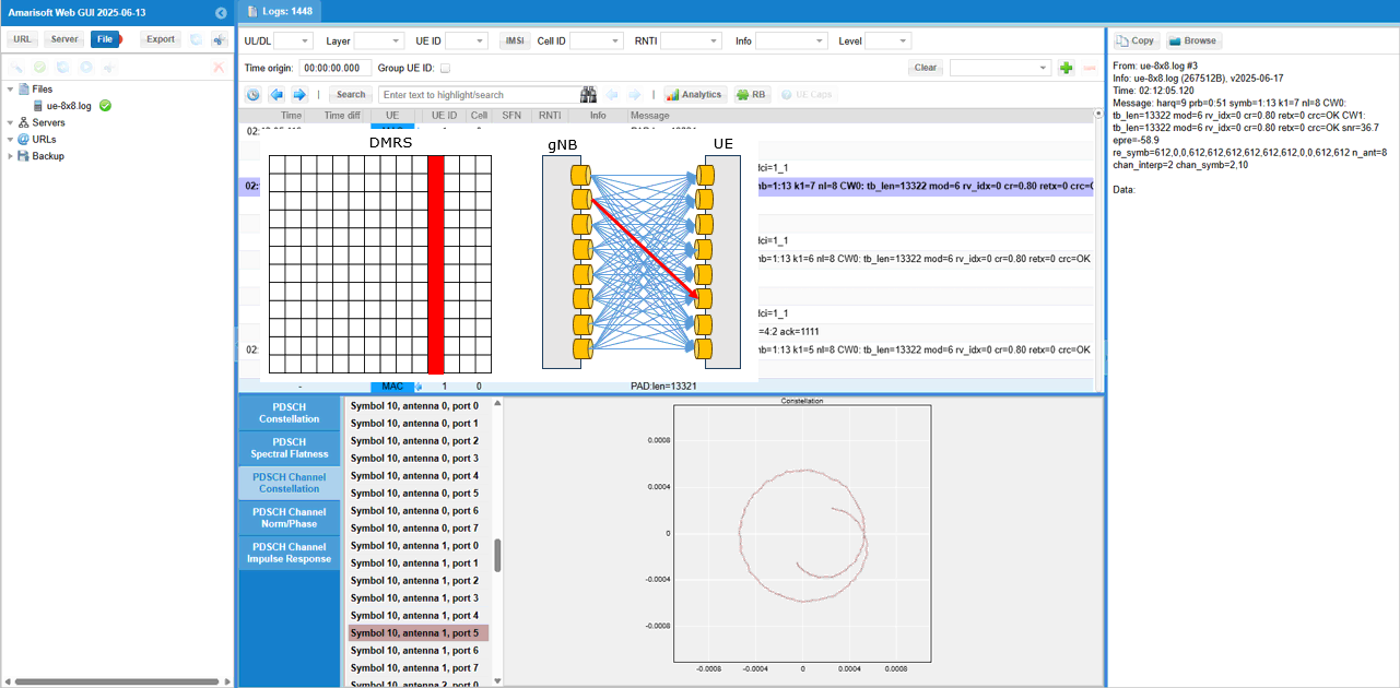
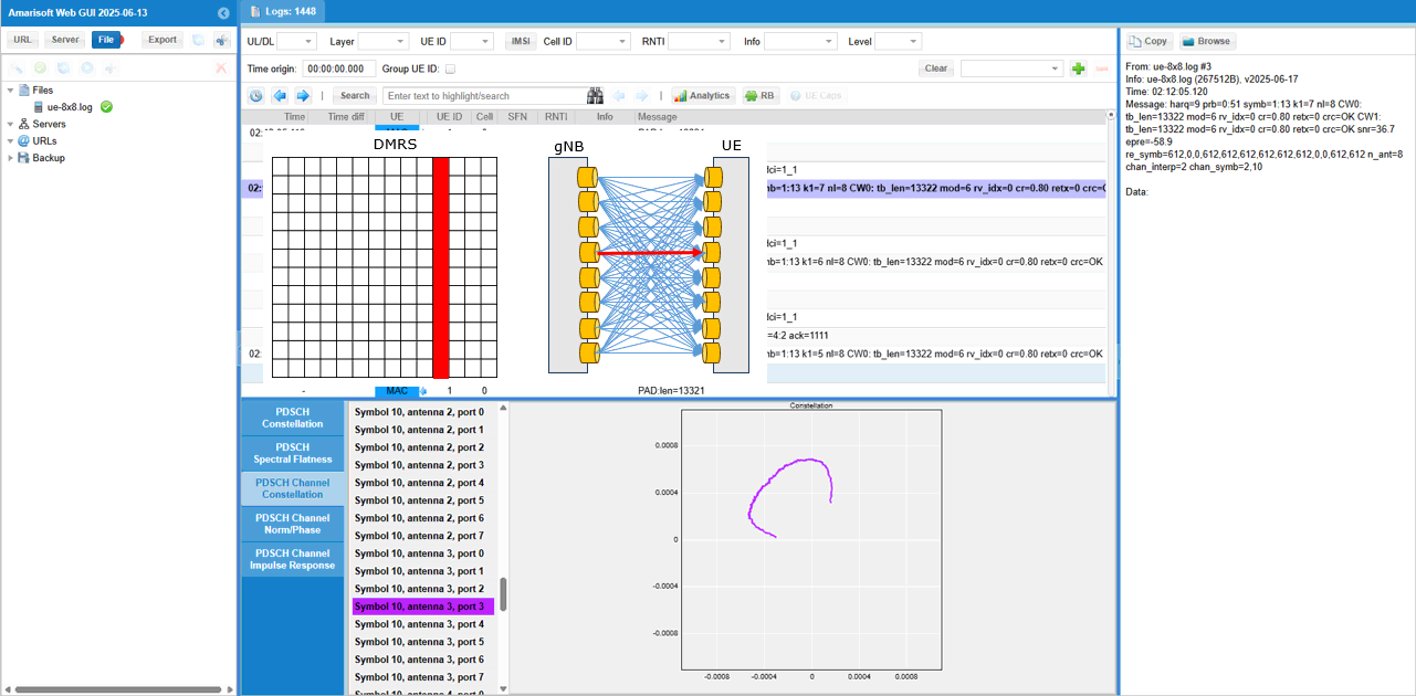
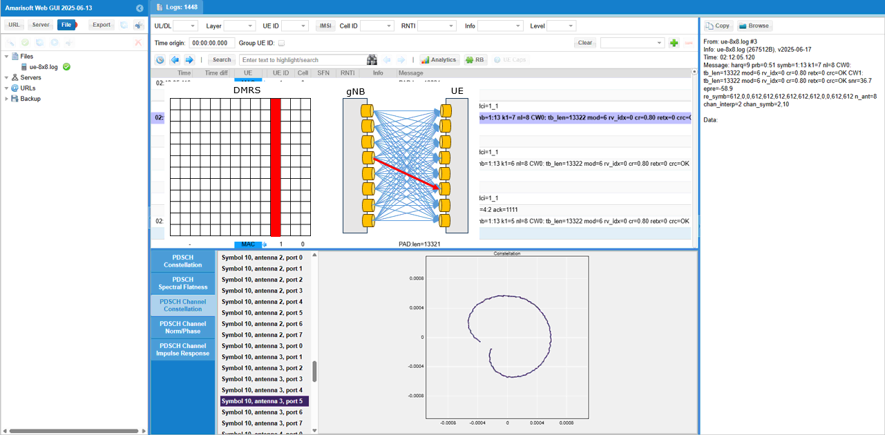
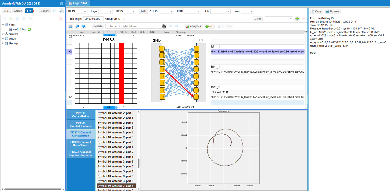
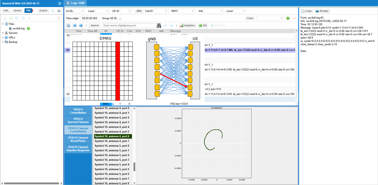
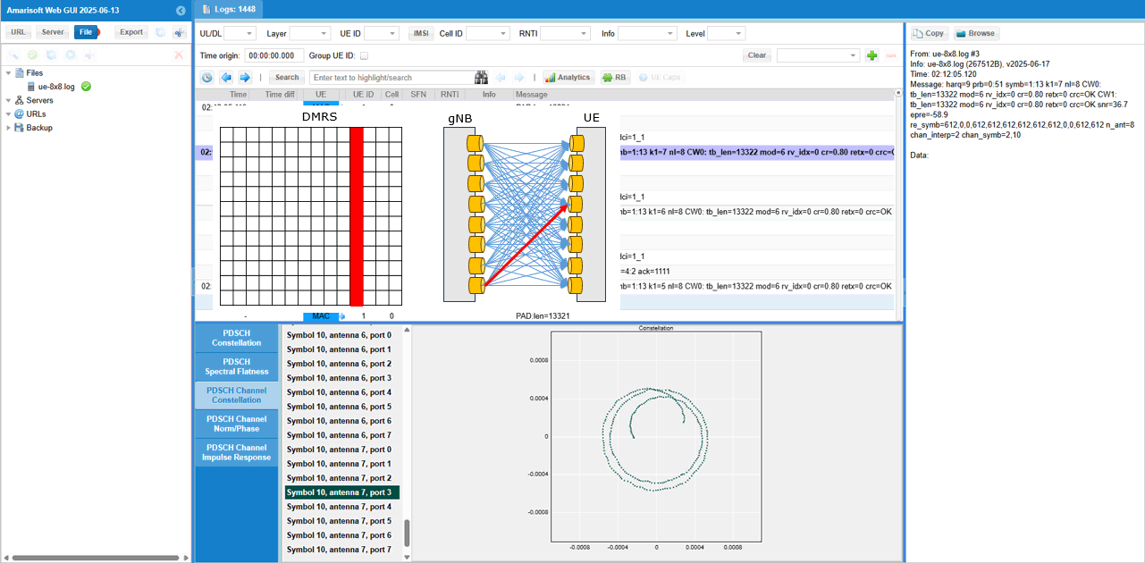
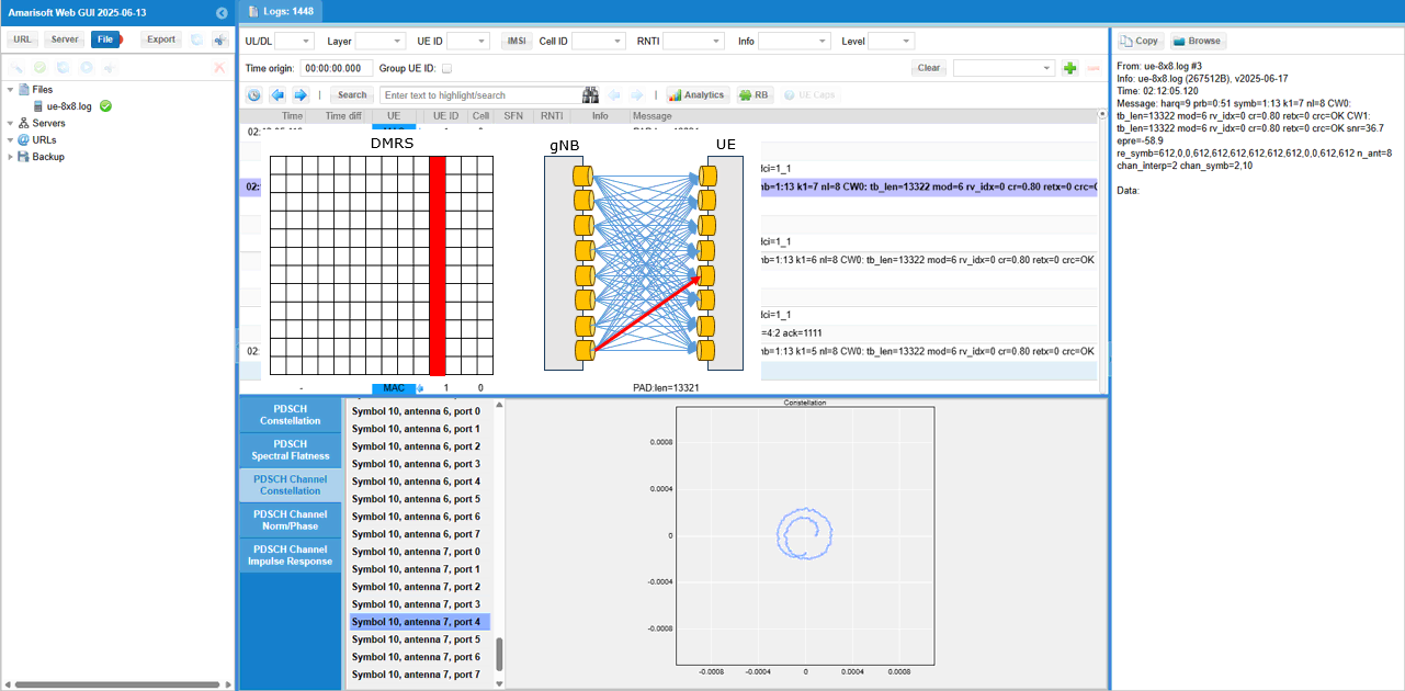
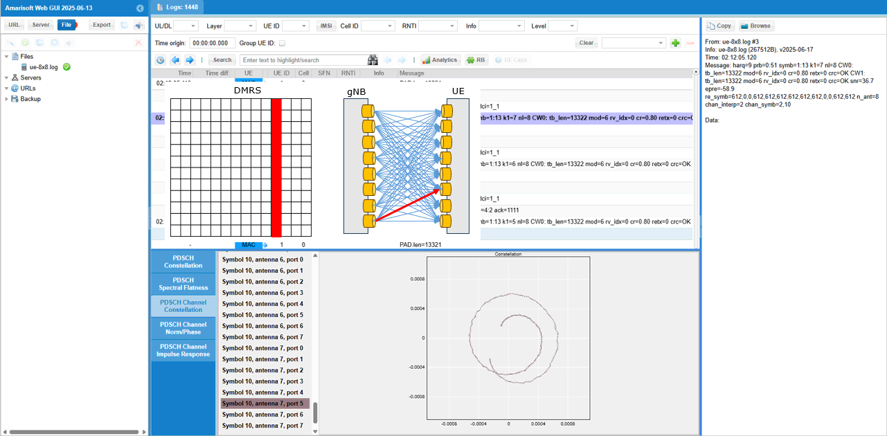
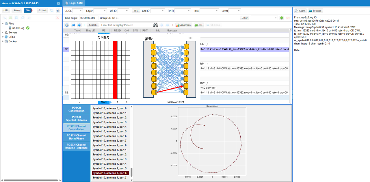
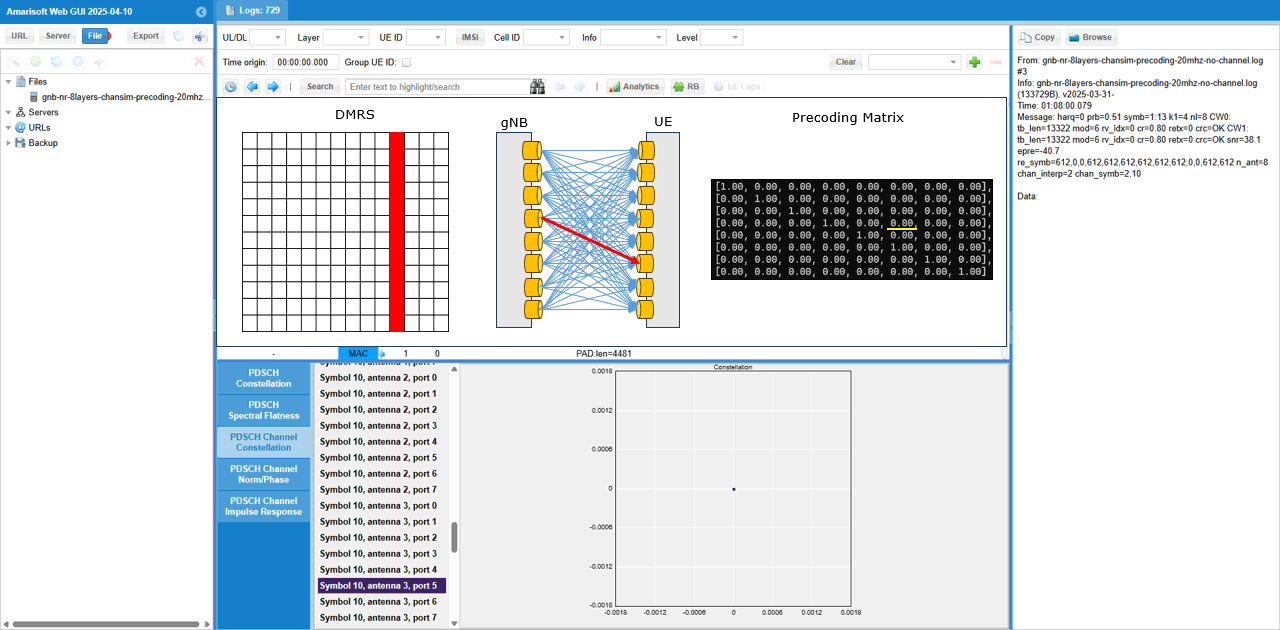
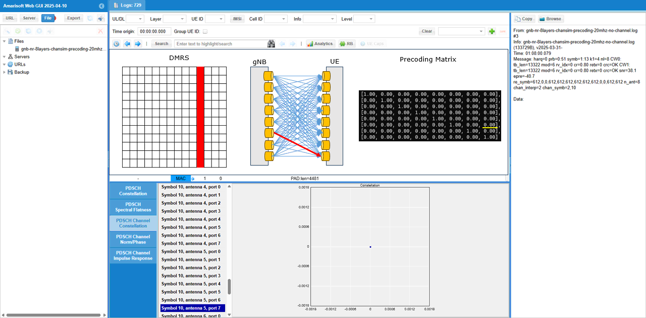
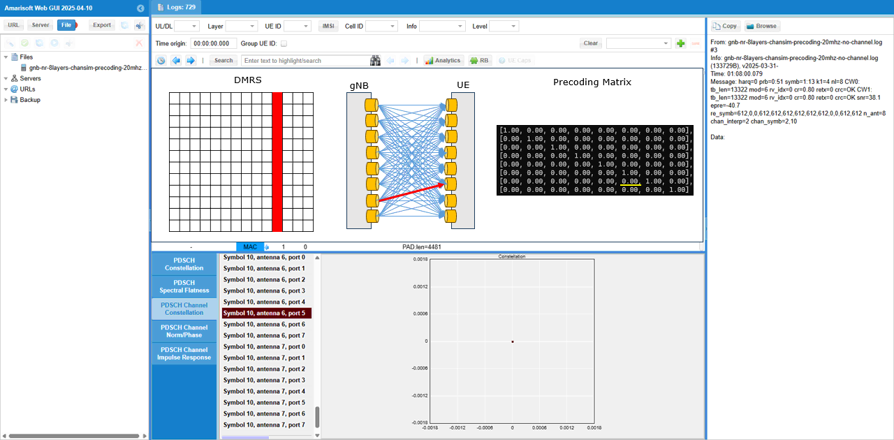
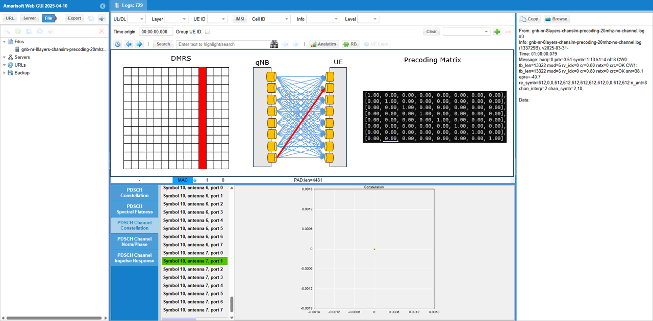
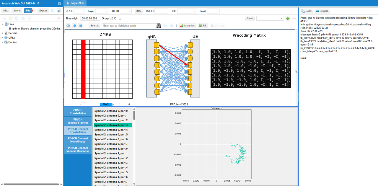
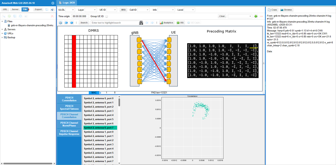
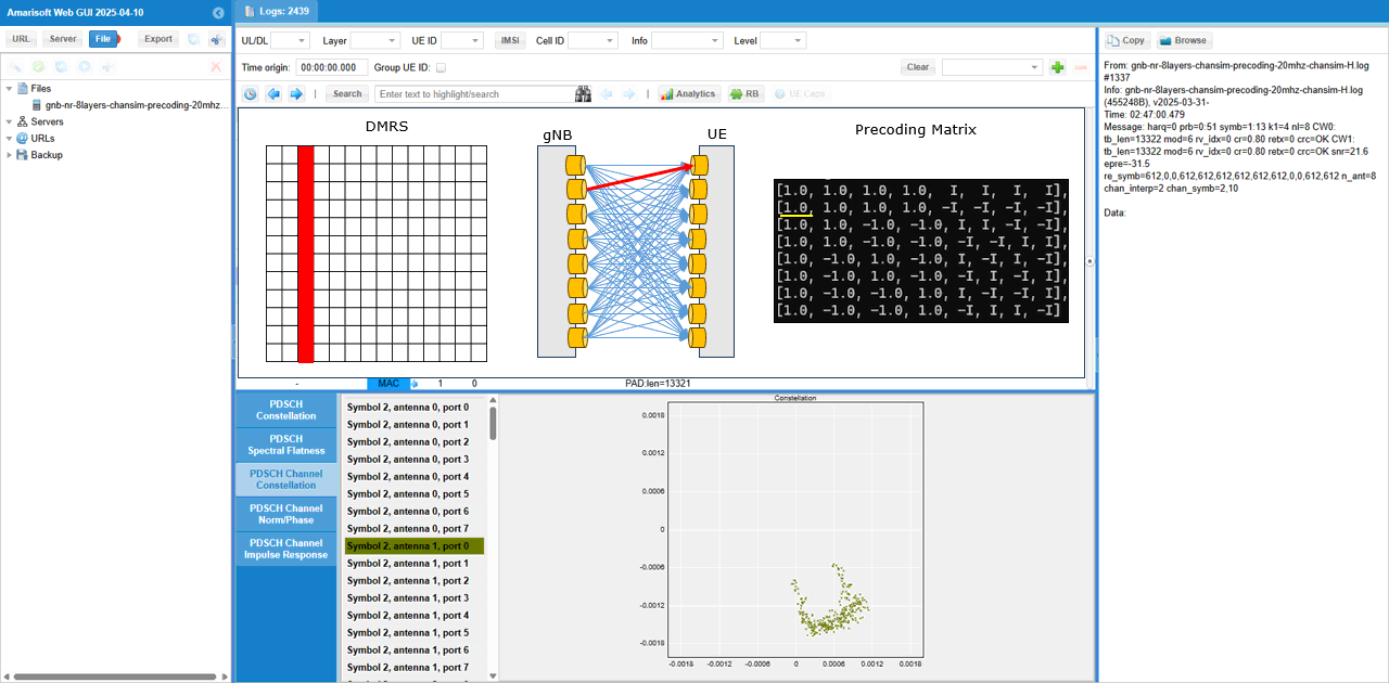
To check out the channel coefficient from a specific TX antenna to a specific RX antenna, I checked(enabled) only one specific radio channel and disabled all the others. The DMRS symbol, the selected radio channel path and corresponding MIMO channel coeffient are shown as a diagram above the channel constellation (


Test 5 : Channel Matrix Analysis : 8x8 MIMO - 2 CW, 8 Layers with channel matrix
Like previous test, this is not really any new test. It is more of analysis for a previous test (Test 3). It is about the analysis of radio channel from each & every TX antenna to each & every RX antenna. I separated this analysis from the previous test since this is too lengthy and would look too complicated.
This is based on the log of Test 3 , captured by UEsim with the log option phy.signal = 1 which is to capture IQ data for every PDSCH..
First pick an any PDSCH and check out overall constellation.
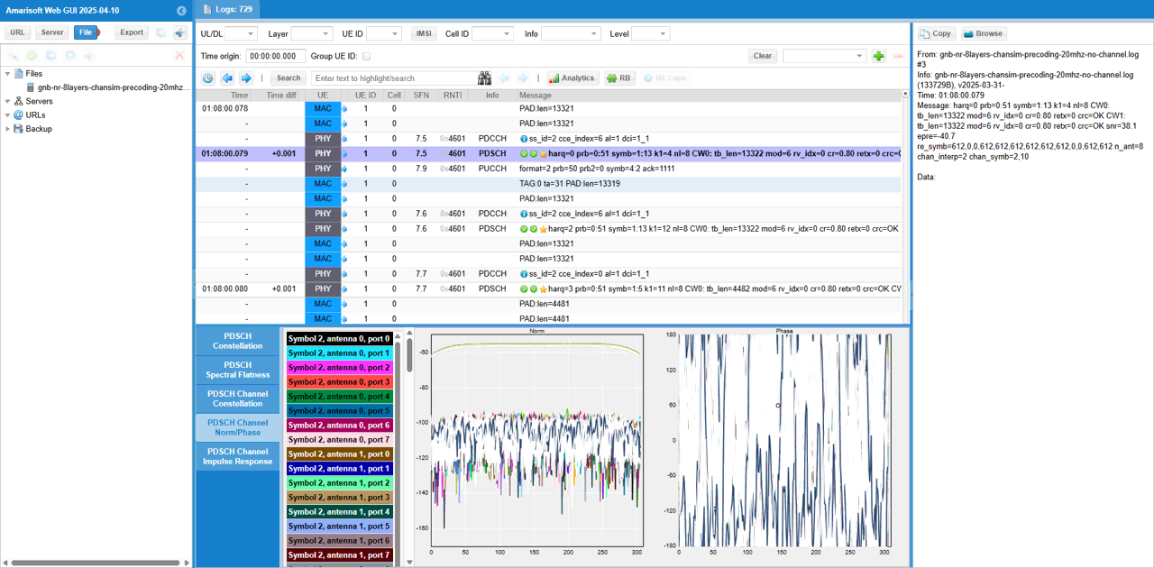
You can check out magnitue and phase of each channel (
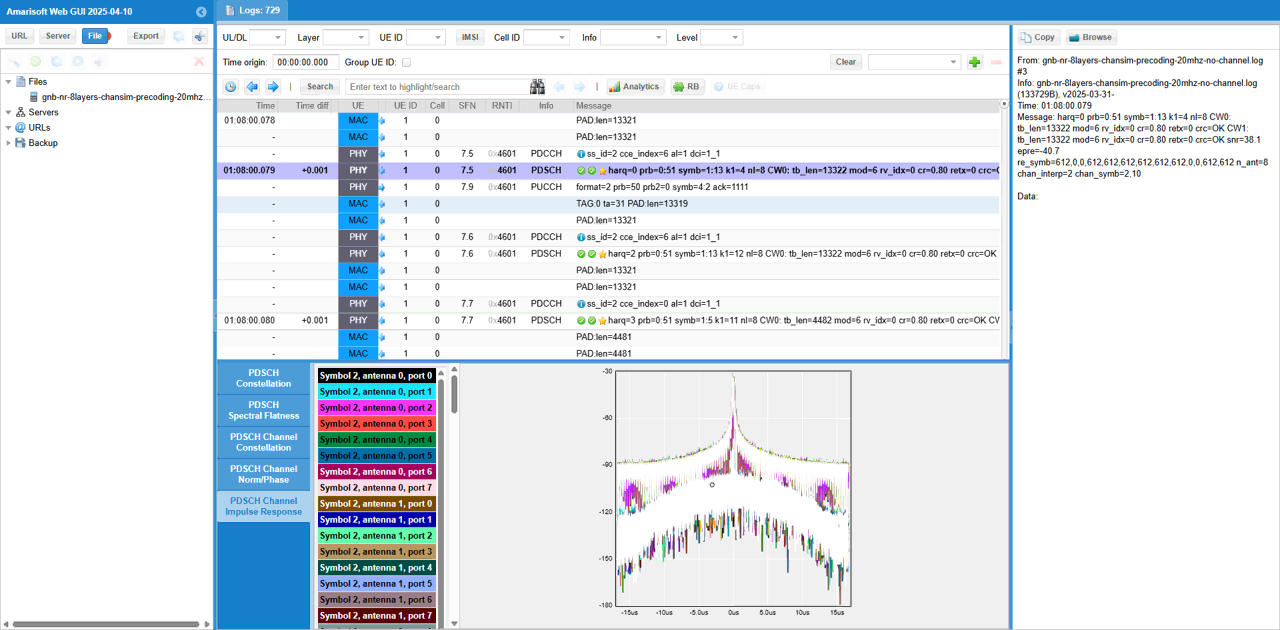
In the same way, you may check out PDSCH Channel Impulse Response. (
What I am intended to show in this test is this plot. This shows the channel coefficent for each & every DMRS RE (Resource Element) of the PDSCH between every TX antenna and every RX antenna. From this plot, it is not clear on how a specific channel from a specific Tx to a specific Rx antenna look like.
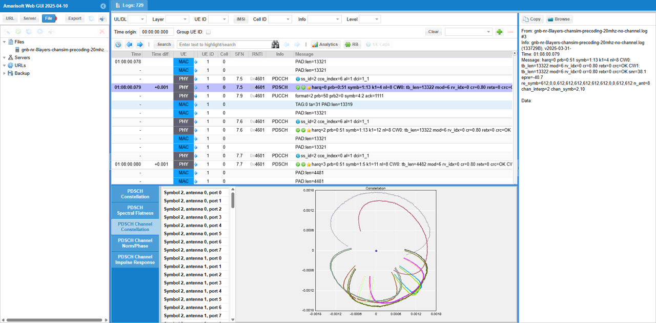
To check out the channel coefficient from a specific TX antenna to a specific RX antenna, I checked(enabled) only one specific radio channel and disabled all the others. The DMRS symbol, the selected radio channel path and corresponding MIMO channel coeffient are shown as a diagram above the channel constellation (


Test 6 : 8x8 MIMO - 2 CW, 8 Layers over the antenna - Channel Coefficient Analysis
This test is to show how to configure and test 8x8 MIMO. The major configuration is about enabling 2 code words and setting proper PDSCH DMRS configuration to match the 8 DMRS ports. The points in this test comparing to previous tests are
- this test is done in radiative condition (i.e, over the antenna)
- MIMO channel is realized by real radio channel. It is not a simulated channel as done in previous test
Configuration
I used the gnb-nr-8layers-20mhz-ota.cfg on gNB

In gnb-nr-8layers-20mhz-ota.cfg , the number of DL antenna is set to 8 (N_ANTENNA_DL = 8) and 2 Code Word flag is enabled (ENABLE_2CW = 1).

Make it sure that you have enough number of SDR cards that can support 8 antenna and all of those necessary SDR cards are enabled.
Channel simulation is not enabled (CHANNEL_SIM = 0) for this test.
Configure any bandwidth and frequency.(
Followings are main configuration for 8x8 MIMO. First 2 codewords are enabled (two_codewords: true), number of layer is set to 8 (n_layer : N_NR_ANTENNA_DL which is set to 8). In order to set 8 DMRS ports for PDSCH, n_dmrs_cdm_groups is set to 2, dmrs_ports is set to [0,1,2,3,4,5,6,7] and dmrs_len is set to 2. (

Perform the Test
Check if the cell is configured as intended. The important thing in this test is Downlink configuration. Check out the number of DL ANT and NL(number of layers) with cell phy command.
Power on UE and establish call. Make it sure that you see ri = 8 which indicates that UE is expecting 8 layer PDSCH. gNB is supposed to transmit 8 layered PDSCH in response to this ri report.
Log Analysis
Overall logic in this log is same as in previous test log. It is more of analysis for a previous test (Test 2). It is about the analysis of radio channel from each & every TX antenna to each & every RX antenna. I separated this analysis from the previous test since this is too lengthy and would look too complicated.
This is based on the log of Test 2 , captured by UEsim with the log option phy.signal = 1 which is to capture IQ data for every PDSCH..
First pick an any PDSCH and check out overall constellation
Then you may check out PDSCH Channel Impulse Response. (
In the same way, you can check out magnitue and phase of each channel(
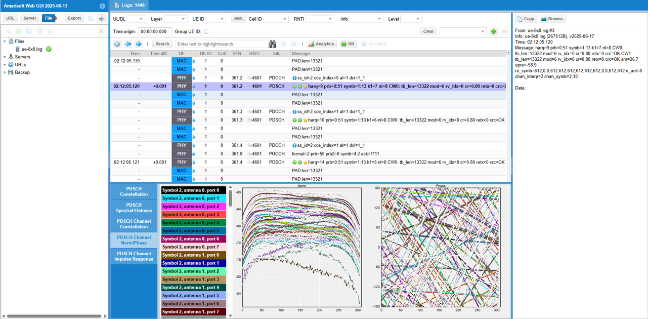
What I am intended to show in this test is this plot. This shows the channel coefficient for each & every DMRS RE (Resource Element) of the PDSCH between every TX antenna and every RX antenna. From this plot, it is not clear on how a specific channel from a specific Tx to a specific Rx antenna look like.
To check out the channel coefficient from a specific TX antenna to a specific RX antenna, I checked(enabled) only one specific radio channel and disabled all the others. The DMRS symbol, the selected radio channel path and corresponding MIMO channel coefficient are shown as a diagram above the channel constellation (