
NR SA Coreset and Search Space
The purpose of this tutorial is to show you how to configure Coreset and Search Space and how those configurations are mapped to RRC message. In addition, this tutorial will explain how each of those search spaces are used throughout the call processing.
Table of Contents
- NR SA Coreset and Search Space
- Introduction
- Summary of the Tutorial
- Test Procedure Summary
- Test Setup
- Key Configuration Parameters
- Test 1 : Single Dedicated Coreset / Single Search Space
- Configuration
- Perform the Test
- Log Analysis
- Sub Test 1 : Single Dedicated Coreset / Single Search Space - Explicit Configurations
- Sub Test 2 : Single Dedicated Coreset / Single Search Space - Explicit Configurations : Assigning css to all transactions
- Sub Test 3 : Single Dedicated Coreset / Single Search Space - Explicit Configurations : Assigning both css and uss
- Test 2 : Multiple Dedicated Coreset / Multiple Search Space - Explicit Configurations : Assigning both css and uss
- RRC / NAS Signaling
Introduction
In 5G NR (New Radio) systems, the configuration and mapping of Control Resource Sets (Coresets) and Search Spaces are fundamental aspects of the physical layer’s control channel operation, directly influencing how downlink control information (DCI) is transmitted and decoded by user equipment (UE). Coresets define specific time-frequency resources within the downlink where the Physical Downlink Control Channel (PDCCH) may be transmitted, while Search Spaces determine the candidate locations within these coreset regions where a UE should monitor for its control information. The flexible and dynamic allocation of these resources enables efficient multiplexing, improved resource utilization, and robust support for a wide variety of service requirements and deployment scenarios in 5G networks. Architecturally, Coreset and Search Space configurations are managed by higher-layer signaling, particularly through RRC (Radio Resource Control) procedures, ensuring that UEs are continuously informed of relevant control channel parameters as the network adapts to changing conditions and service demands. This mechanism is critical for enabling features such as dynamic scheduling, beamforming, and network slicing, and plays a pivotal role in the overall 5G system’s performance and reliability. As the industry moves towards increasingly complex and heterogeneous network deployments, a thorough understanding of Coreset and Search Space configuration becomes essential for engineers, network architects, and anyone involved in the design or optimization of 5G NR systems.
-
Context of the Technology
- 5G NR introduces advanced control channel mechanisms, where Coresets and Search Spaces define how and where control information is delivered to UEs.
- These configurations are central to the flexible and scalable resource management required in next-generation mobile networks.
- Unlike LTE, where control channels have fixed resources, 5G NR supports dynamic and UE-specific control channel mapping, enhancing efficiency and supporting diverse use cases.
-
Relevance and Importance
- Proper configuration of Coreset and Search Space is essential for reliable and optimized downlink control signaling.
- Understanding these concepts enables network designers and engineers to tailor control channel behavior to specific deployment scenarios and service requirements.
- Non-Coreset 0 and non-Search Space 0 configurations are especially relevant for advanced scheduling and enhanced mobility procedures in 5G NR.
-
What You Will Gain from This Tutorial
- A clear understanding of the architectural concepts behind Coreset and Search Space in 5G NR.
- Insights into how these configurations are signaled via RRC procedures and mapped to network messages.
- Practical knowledge on how different search spaces are utilized throughout the call processing phases.
- The ability to interpret and apply configuration information in real-world 5G NR deployment and troubleshooting scenarios.
-
Prerequisite Knowledge and Skills
- A basic understanding of 5G NR system architecture and protocol stack.
- Familiarity with physical layer concepts such as PDCCH, OFDM resource grids, and downlink scheduling.
- Experience with RRC signaling and network configuration procedures is helpful but not strictly required.
- For comprehensive background on Coreset 0, refer to the dedicated tutorial linked in the source content.
Summary of the Tutorial
This tutorial demonstrates configuration and testing procedures for PDCCH (Physical Downlink Control Channel) coreset and search space mapping in NR (New Radio) SA (Standalone) mode, focusing on practical test setups and step-by-step methodologies. The procedures cover both basic and advanced configurations, including multiple subtests to show explicit mapping and assignment of resources for different protocol transactions.
- Test Preparation:
- Only gNB configuration is required; default MME and IMS configurations can be retained.
- Set desired TDD/FDD mode, number of DL antennas, band, frequency, and bandwidth.
- Configure PDCCH parameters: search_space0_index, dedicated_coreset, css, uss, rar_al_index, si_al_index, al_index (for controlling aggregation levels and candidate numbers for different search spaces and protocol transactions).
- Test setup uses supplied SIM card and minimal IP layer configuration.
- Key Configuration Parameters:
- Focus is on PDCCH-related parameters, especially common_coreset, dedicated_coreset, css, uss and their respective child parameters.
- Explicit assignment of aggregation level indices for various protocol transactions (RAR, SIB, user data) is highlighted as a method for granular control.
Test 1: Single Dedicated Coreset / Single Search Space
- Demonstrates default and explicit mapping of configuration parameters to protocol IEs for a single coreset and search space.
- Common configuration file is prepared and modified.
- Key steps:
- Set TDD pattern, bandwidth, MIMO configuration, and band.
- Enable only SSB 0 and configure CSI-RS to avoid collision.
- Map css to pdcch-ConfigCommon in SIB1 and uss to pdcch-Config in RRC Setup.
- Confirm correct mapping of n_candidates to respective protocol elements.
- Run the test, power on UE, ensure attachment and traffic flow.
- Analyze logs to verify mapping and application of search spaces for SIB, RAR, RRC, and user traffic.
Sub Test 1: Explicit Configurations
- Similar to the main test, but with explicitly assigned coreset_id and search_space_id.
- Assigns aggregation levels explicitly for RAR, SIB, and user traffic.
- Logs are analyzed to confirm these explicit assignments are reflected in protocol messages and scheduling.
Sub Test 2: Assigning CSS to All Transactions
- Demonstrates the use of dl_search_space and ul_search_space parameters to force all transactions to use the CSS.
- Shows configuration and log verification for the effect of these assignments.
Sub Test 3: Assigning Both CSS and USS
- Shows explicit assignment of specific search spaces for each transaction using dl_search_space and ul_search_space parameters.
- Only specific transactions (e.g., RAR, RRC with PHY config) use CSS; others use the search space defined by dl_search_space and ul_search_space.
- Logs validate the selective search space usage.
Test 2: Multiple Dedicated Coreset / Multiple Search Space
- Extends the previous tests to include multiple dedicated and common coresets and search spaces.
- Configuration files are expanded to define several coresets and search spaces, providing gNB with the ability to select depending on context.
- Highlights:
- Multiple common_coreset and dedicated_coreset definitions.
- Assignment of search spaces for various transactions with rar_search_space, dl_search_space, ul_search_space parameters.
- Verifies in logs that correct search space and coreset assignments are used for each protocol transaction.
General Methodology:
- For each test, confirm gNB and UE configuration using provided tools (e.g., cell phy commands).
- Power on UE and verify attachment completion and data flow.
- Analyze logs to correlate configuration with protocol message fields and to observe scheduling behavior for SIB1, RAR, RRC Setup, and user data messages.
- Pay particular attention to mapping between configuration parameters and protocol IEs for control resource sets and search space assignments.
Notes:
- Explicit configuration of coreset_id and search_space_id allows for fine control over scheduling and resource mapping.
- Aggregation levels can be tuned for each protocol transaction to match specific test requirements.
- Multiple coresets and search spaces provide flexibility for different scheduling scenarios and are useful for advanced test cases.
Test Procedure Summary
This test requires gNB configuration change only and you can keep mme, ims configuration as in default.
Step 1 : Set TDD/FDD(NR_TDD). number of DL Antenna(N_ANTENNA_DL), Band(band) and Frequency(dl_nr_arfcn) and Bandwidth(NR_BANDWIDTH) as you want
Step 2 : Configure pdcch parameter as per your requirement. search_space0_index, dedicated_coreset, css, uss, rar_al_index,si_al_index and al_index are the detailed parameters you need to configure. css is the parameter for common search space and uss is the parameter for user specific search space where you can specify the number of candidates for each aggregation level. rar_al_index, si_al_index and al_index are parameters indicating the specific aggregation level and number of candidates for RAR, SIB and user data respectively.
Step 3 : Run the test
Step 4 : Verify the result with Log. Check SIB for verifying the configuration on CSS (Common Search Space) and RRC Setup message for USS. Check PDCCH log to see which specific search space are applied for each PDCCH.
Test Setup
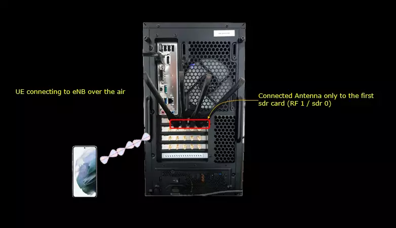
Test setup for this tutorial is as shown below. This is just for low layer testing, you may not need any complicated IP layer setup.
- SIM Card used in this tutorial is the one delivered with the system as it is.
- If you want to change the configuration, The tutorial Configuration Guide would help
Key Configuration Parameters
Followings are important configuration parameters for this tutorial. You may click on the items for the descriptions from Amarisoft documents.
- pdcch
- common_coreset
- coreset_id
- rb_start
- l_crb
- rb_list
- duration
- interleaved
- reg_bundle_size
- interleaver_size
- shift_index
- precoder_granularity
- dmrs_scid
- tci_states_pdcch
- dedicated_coreset
- css
- uss
- search_space_id
- n_candidates
- start_symb
- coreset_id
- css
- dci_0_1_and_1_1
- slot_period
- slot_duration
- force_cce0
- force_dci_0_0
- rar_search_space
- dl_search_space
- ul_search_space
- coreset0_index
- search_space0_index
- n_rb_coreset0
- n_symb_coreset0
- offset_rbs_coreset0
- rar_al_index
- al_index
- si_al_index
- paging_al_index
- pei_al_index
Test 1 : Single Dedicated Coreset / Single Search Space
In this test, I am trying to show you how to interpret each of the configuration parameters from default setting(gnb-sa.cfg) and how to correlate the configuration with IE(information elements) in RRC messages. Then I will add multiple subtests. In the subtest, I will add some additional configuration parameters to have more controll over the coreset/searchspace mapping or control on which search space is supposed to be when.
Configuration
The configuration shown here is common configuration for all the subtests belonging to Test 1 and I will not show this configuration repeatedly for every subtest.
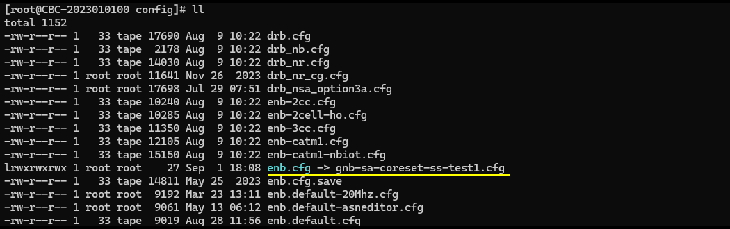
I have used gnb-sa-coreset-ss-test1.cfg which is copied and modified from gnb-sa.cfg
I am using the default mme, ims config as shown below.

In gnb-sa-coreset-ss-test1.cfg, it is configured as follows.
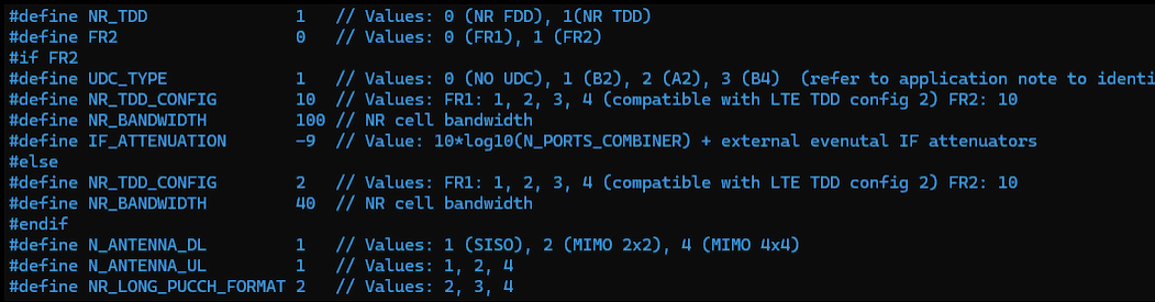
In the configuration file, you can select any specific tdd pattern with the parameter NR_TDD_CONFIG. To apply TDD configuration, you first need to configure the duplex mode (NR_TDD) to 1 (TDD). And then I set NR_TDD_CONFIG to 2 which is one of default sample configuration provided by Amarisoft sample configuration. And I set the channel bandwidth (NR_BANDWIDTH) to 20Mhz and 2x2 MIMO (N_ANTENNA_DL = 2)
These defines sit in an #if FR2 / #else / #endif block and FR2 is set to 0 here, so the FR1 branch after #else is the one that is compiled. The FR2 branch above it, with UDC_TYPE 1, its own NR_TDD_CONFIG 10 and IF_ATTENUATION -9, is not used in this tutorial. NR_TDD_CONFIG accepts 1, 2, 3 or 4 for FR1 and those four patterns are the ones compatible with LTE TDD config 2, while 10 is the value used only on the FR2 side.
NR_TDD is the switch that decides whether any of this applies at all. If you set it back to 0 the cell becomes FDD and NR_TDD_CONFIG stops taking effect. NR_LONG_PUCCH_FORMAT is left at 2 and I did not touch it for this test.
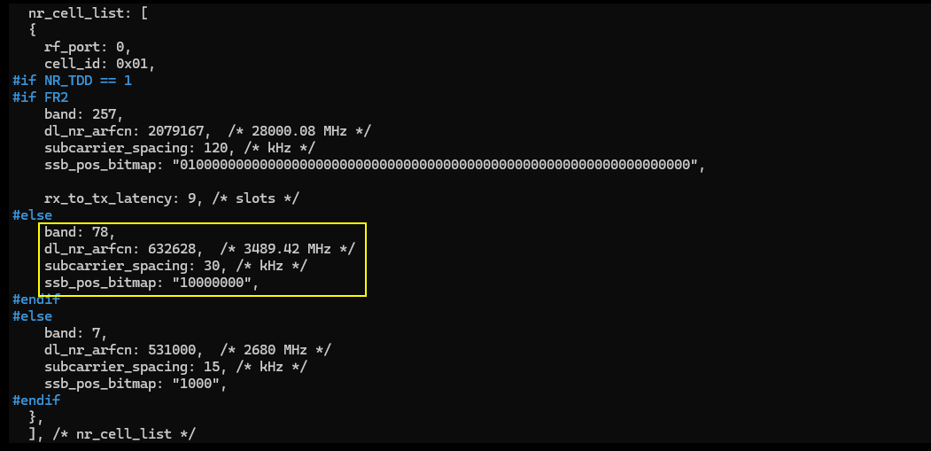
Here the band is set to n78 which is a TDD band. The important part is ssb_pos_bitmap. In this test, only ssb 0 is enabled and all the csi-rs is configured not to collide with the ssb 0 symbols. If you want to change this part, you may need to change CSI-RS symbols accordingly not to collide the changed ssb burst position.
The cell entry that is actually used here is the one under #if NR_TDD == 1 and #else, meaning the FR1 TDD branch. It sets band 78, dl_nr_arfcn 632628 which is 3489.42 MHz, subcarrier_spacing 30 kHz and ssb_pos_bitmap "10000000". The bitmap is 8 bits long for this band and only the leading bit is set, which is what leaves ssb 0 as the only transmitted SSB. The cell itself is on rf_port 0 with cell_id 0x01.
The two other branches in the same nr_cell_list are there only so that the same file can be reused. The FR2 branch uses band 257 at dl_nr_arfcn 2079167 (28000.08 MHz) with 120 kHz subcarrier spacing and a 64 bit ssb_pos_bitmap, and the FDD branch at the bottom uses band 7 at dl_nr_arfcn 531000 (2680 MHz) with 15 kHz subcarrier spacing and a 4 bit bitmap. Neither of them is exercised in this tutorial.
If you want to run this on a different frequency, band and dl_nr_arfcn have to be changed together and subcarrier_spacing has to stay legal for the band you pick. Enabling more than one SSB position is a matter of setting more bits in ssb_pos_bitmap, and that is exactly the change that forces you to revisit the CSI-RS symbols.
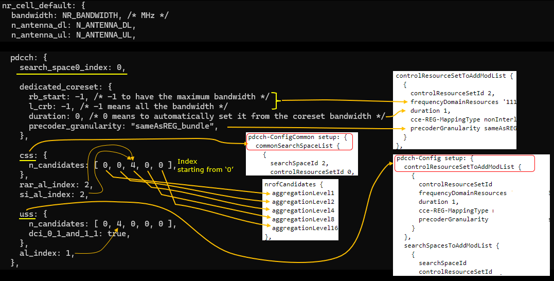
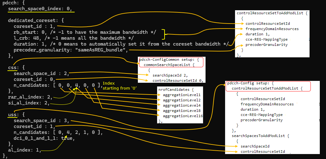
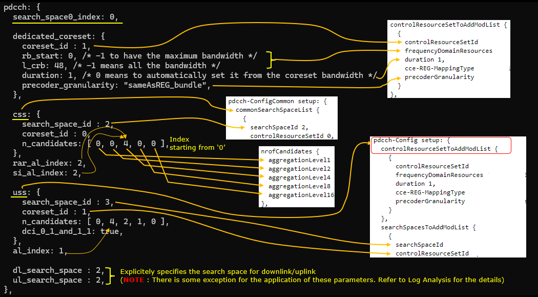
Here comes the tricky and confusing part. Sorry for spaghetti like arrows, but this is the best I can do for now. Flow through each of the lines and arrows whenever you are confused with which parameters are mapped to which IE(information elements) in RRC. Just as high level descriptions :
- css maps to pdcch-ComfigCommon in SIB1
- uss maps to pdcch-Config in RRC Setup or RRC Reconfiguration
- n_candiates maps to nrofCanadiates in searchSpacesToAddModList
- You can explicitely specify which aggregation level(AL) should be used for which specific transactions in protocol sequence (e.g, rar_al_index for RAR, si_al_index for SIBs(Other SIBs), al_index for other general user traffcis etc)
The whole pdcch block sits inside nr_cell_default, right under bandwidth, n_antenna_dl and n_antenna_ul, and it opens with search_space0_index set to 0. Everything below that line is what ends up in the two RRC containers on the right, pdcch-ConfigCommon in SIB1 and pdcch-Config in RRC Setup.
dedicated_coreset is left almost entirely on automatic here. rb_start and l_crb are both -1, which means take the maximum bandwidth, and duration is 0, which means let the gNB derive the number of symbols from the coreset bandwidth. Only precoder_granularity is stated explicitly as "sameAsREG_bundle". On the RRC side these become controlResourceSetId 2 with its frequencyDomainResources bitmap, duration 1, cce-REG-MappingType and precoderGranularity sameAsREG-bundle in controlResourceSetToAddModList.
n_candidates is an array with one entry per aggregation level, and the five arrows leaving it land on aggregationLevel1, aggregationLevel2, aggregationLevel4, aggregationLevel8 and aggregationLevel16 in nrofCandidates in that order. css has [ 0, 0, 4, 0, 0 ], so the common search space gets 4 candidates at aggregation level 4 and nothing anywhere else. uss has [ 0, 4, 0, 0, 0 ], so the user specific search space gets 4 candidates at aggregation level 2.
The index that rar_al_index, si_al_index and al_index carry counts positions in that same array and it starts from 0, not from 1. rar_al_index 2 and si_al_index 2 therefore point at the third entry of the css array, which is the one holding 4 candidates at aggregation level 4, and al_index 1 points at the second entry of the uss array, which is the one holding 4 candidates at aggregation level 2. Lining the indices up with the non zero entries is the part worth checking whenever you change n_candidates. uss also carries dci_0_1_and_1_1 set to true, which is what puts the non fallback DCI formats on the user specific search space.
Perform the Test
Check cell configurations with cell phy and cell command to confirm that cell configuration is properly configured as you intended.
cell phy prints one row per cell and here there is a single NR cell, 0x001, on band n78 with dl and ul arfcn both 632628 and 30 kHz subcarrier spacing on each side, and 256QAM allowed in both directions. The SSB is reported separately at arfcn 631968 with 30 kHz spacing, which is the value you want to compare against the ssb_pos_bitmap and the frequency you set in the configuration file. The header line confirms PLMN 00101 and gNB_ID 0x12345.
cell adds what phy does not show, TAC 0x000064, pci 500, prach_seq 1 and dl_gain 0.0. Neither command shows coreset or search space contents, so this step is only about proving that the cell came up on the frequency you intended before you start reading PDCCH logs.

Power on UE and make it sure the attach is complete and some traffic goes on.
t starts the running trace and stays up until you press return. The PRACH line comes first, cell=01 seq=0 ta=7 snr=21.2 dB, and that is the preamble the RAR in the log analysis below is answering.
After that the per UE rows appear for UE_ID 1 on cell 001 with RNTI 4601, and that RNTI is the one to keep in mind because it is what the PDCCH entries in the log are addressed to. The downlink starts at mcs 18.2 with 5.65k bitrate and settles at mcs 26.8 with cqi 15 and ri 1, while the uplink reports snr 40.7 with phr 22 and pl 71. There is nothing to tune here, the rows only need to keep moving so that there is dedicated traffic to look at.

Log Analysis
This is just for showing the association between the configuration shown above and IE (Information Elements) in RRC.
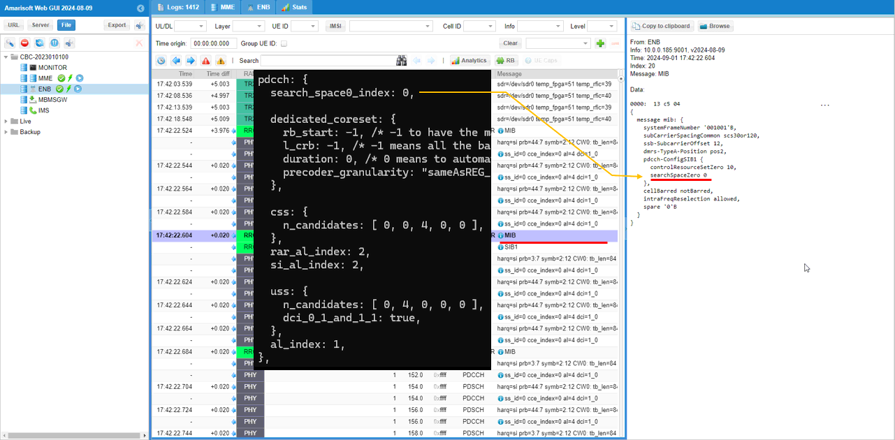
First you would check out how search_space0_index is mapped to RRC. It is mapped to searchSpaceZero IE in pdcch-ConfigSIB1 of MIB.
In this run pdcch-ConfigSIB1 comes out as controlResourceSetZero 10 and searchSpaceZero 0. searchSpaceZero 0 is the search_space0_index you set in the configuration file, and controlResourceSetZero 10 is the companion value that comes from coreset0_index. These two are the only PDCCH related fields in MIB, and they are what the UE has to work with before it has any SIB.
The rest of the MIB in this log is the usual set, systemFrameNumber '001001'B, subCarrierSpacingCommon scs30or120, ssb-SubcarrierOffset 12, dmrs-TypeA-Position pos2, cellBarred notBarred and intraFreqReselection allowed. If you want to follow the same trace, MIB is repeated often enough that any of the MIB rows in the message list will do.
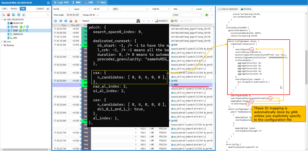
Now let's take a look at how css parameter is mapped to RRC. It is mapped to pdcch-ConfigCommon in SIB1. css parameter (object) has many child paramters in it, but by default we usually specify agrregation level with the parameter n_candidates. n_candidates is mapped to nrofCandiates IE and each of the elements in n_candidates array maps to each elements of nrofCandidates IE.
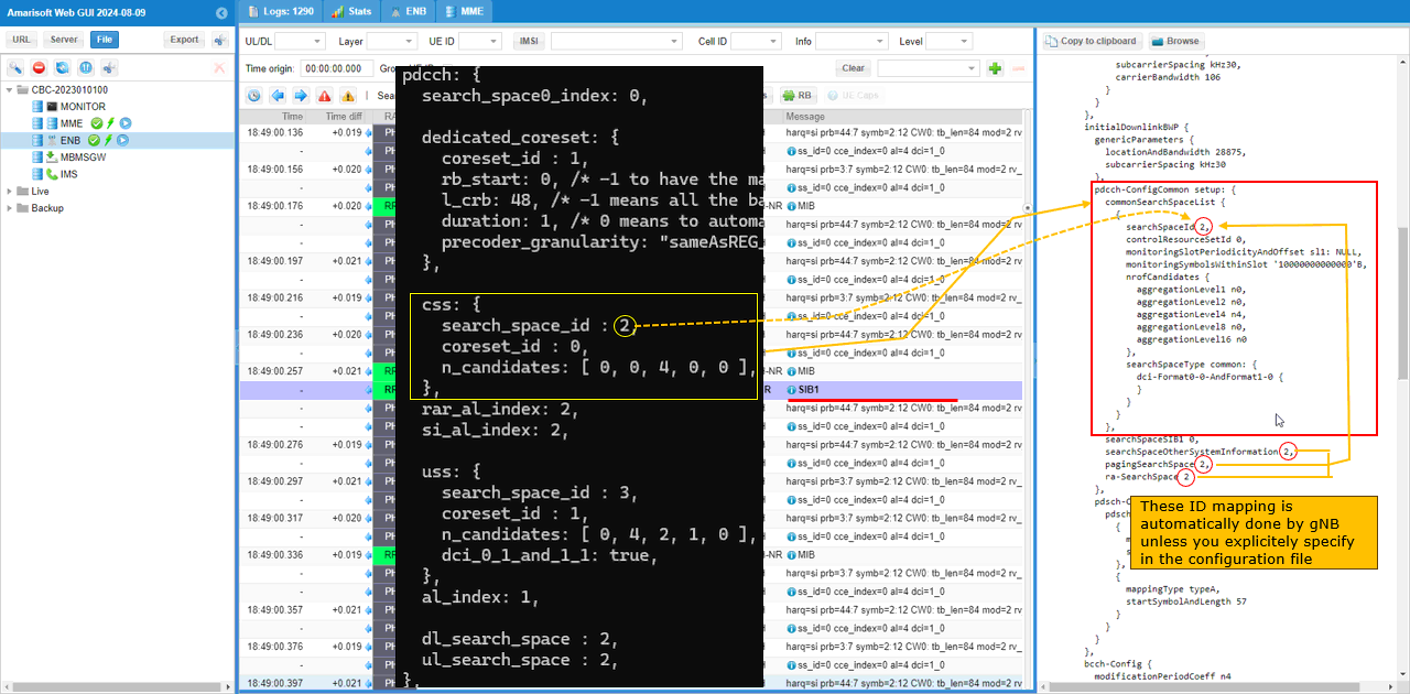
Another important thing worth paying attention to are searchSpaceOtherSystempInformation, pagingSearchSpace and ra-SearchSpace in RRC. In the configuration file of this test, I haven't specified these value. In this case, those IEs uses the seachSpaceID specified in commonSearchSpaceList.
commonSearchSpaceList has a single entry in this run and it comes out as searchSpaceId 1 with controlResourceSetId 0. controlResourceSetId 0 is coreset 0, and it lands there because no common_coreset was configured in this test, so the common search space has nowhere else to sit. The monitoring fields are monitoringSlotPeriodicityAndOffset sl1 and monitoringSymbolsWithinSlot '10000000000000'B, which is every slot on the first symbol.
nrofCandidates comes out as aggregationLevel1 n0, aggregationLevel2 n0, aggregationLevel4 n4, aggregationLevel8 n0 and aggregationLevel16 n0. That is the css n_candidates array [ 0, 0, 4, 0, 0 ] entry by entry, with the single 4 sitting on aggregation level 4. searchSpaceType comes out as common with dci-Format0-0-AndFormat1-0, so only the fallback DCI formats are monitored here.
searchSpaceSIB1 stays at 0, which is search space 0 and not the entry in this list, while searchSpaceOtherSystemInformation, pagingSearchSpace and ra-SearchSpace all take 1, the id of the single entry in commonSearchSpaceList. The gNB fills those three in on its own, and the only way to take them over is to write the ids into the configuration file yourself, which is what Sub Test 1 below does.
Now let's confirm how each of these search spaces are applied to each of the transactions in protocol sequence.
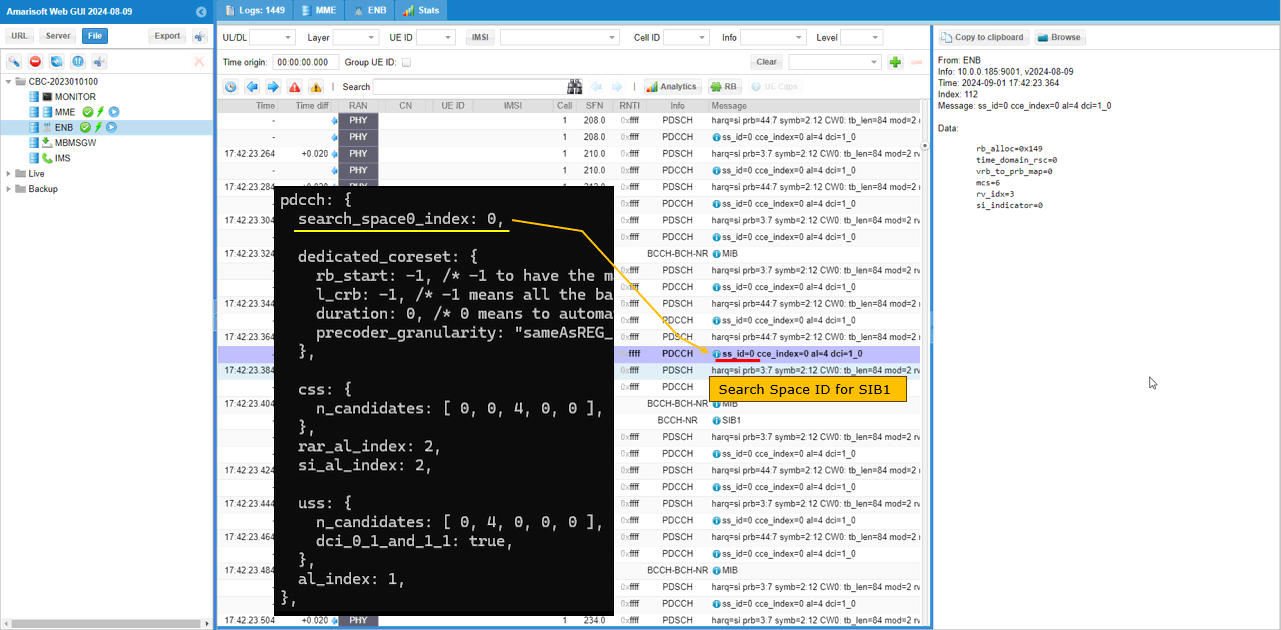
You can confirm that PDCCH for SIB1 uses ss_id configured by search_space0_index.
The PDCCH entry that carries SIB1 reads ss_id=0 cce_index=0 al=4 dci=1_0, and the SIB1 row follows it a few lines below. ss_id 0 is the search_space0_index value straight out of MIB, and this is the one PDCCH in the whole sequence that is not described anywhere in SIB1, because at this point the UE has nothing but MIB to go on. dci=1_0 is the fallback downlink format, which is the only downlink format a common search space carries.
The grant behind it is rb_alloc=0x149, time_domain_rsc=0, vrb_to_prb_map=0, mcs=6, rv_idx=3 and si_indicator=0. None of these come from the pdcch block, they come from the SI scheduler, but the field list is a quick way to tell a SIB grant apart from the RAR and dedicated grants further down, which carry a different set of fields altogether.
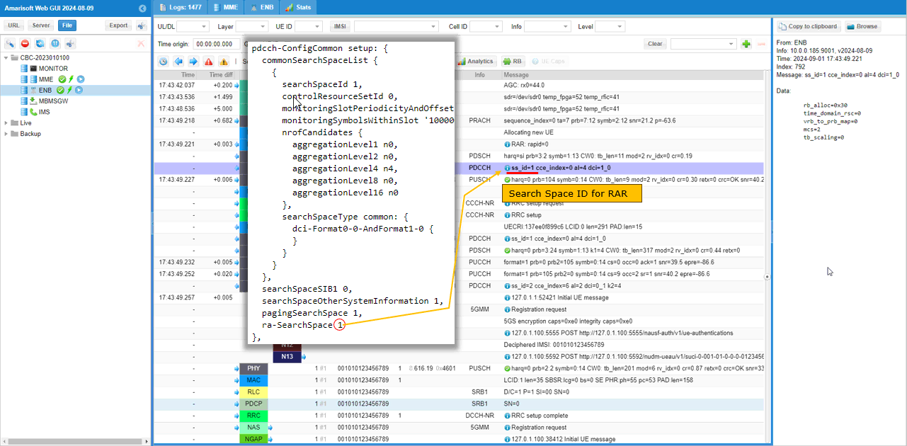
You can confirm that PDCCH for RAR uses ss_id configured in ra-SearchSpace IE in SIB. (
The PDCCH entry here reads ss_id=1 cce_index=0 al=4 dci=1_0, and 1 is exactly the value ra-SearchSpace carries in SIB1. The aggregation level 4 is what rar_al_index 2 asked for, since index 2 of the css n_candidates array is the entry holding 4 candidates at aggregation level 4. This is the first PDCCH in the sequence whose search space the UE learned from SIB1 rather than from MIB.
The chain around it is worth following in one go. PRACH is detected with sequence_index=0 ta=7 snr=21.2, the RAR that this PDCCH schedules comes out as rapid=0, and RRC setup request and RRC setup follow immediately after. The grant itself is rb_alloc=0x30, time_domain_rsc=0, vrb_to_prb_map=0, mcs=2 and tb_scaling=0, and tb_scaling is a field you will not find on the SIB1 grant above.
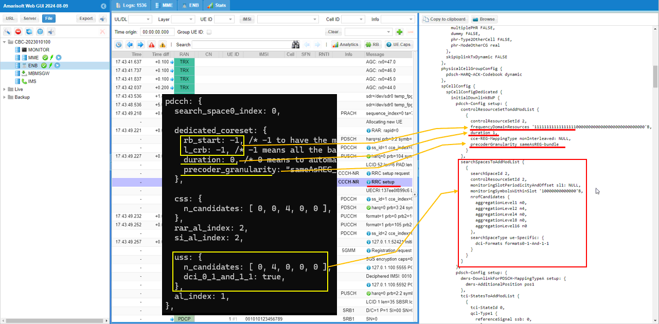
Now let's take a look at how dedicated coreset and uss are configured and how they are mapped to RRC. High level mappings are as follows :
- rb_start and l_crb in configuration file are mapped to frequencyDomainResources in controlResourceSetToAddModList (
NOTE : 6 consecutive RBs corresponds to single bit '1' in frequencyDomainResources) - duration in configuration file maps to duration in controlResourceSetToAddModList
- precoder_granularity in configuration file maps to precoderGranularity in controlResourceSetToAddModList
Both of these live under spCellConfigDedicated, initialDownlinkBWP, pdcch-Config in the RRC Setup. The coreset comes out as controlResourceSetId 2 with frequencyDomainResources carrying a run of leading 1 bits and zeros for the rest, which is what rb_start -1 and l_crb -1 produce, one bit per 6 RB across the whole bandwidth. duration is reported as 1 even though the configuration file says 0, because 0 only means let the gNB work it out from the coreset bandwidth. cce-REG-MappingType is nonInterleaved and precoderGranularity is sameAsREG-bundle, the latter being the one value that was written explicitly.
searchSpacesToAddModList right below it comes out as searchSpaceId 2 bound to controlResourceSetId 2, which is the dedicated coreset just above, with monitoringSlotPeriodicityAndOffset sl1 and monitoringSymbolsWithinSlot '10000000000000'B. nrofCandidates has aggregationLevel2 n4 and n0 on everything else, which is the uss n_candidates array [ 0, 4, 0, 0, 0 ]. searchSpaceType is ue-Specific with dci-Formats formats0-1-And-1-1, and that is dci_0_1_and_1_1 set to true in the configuration file.
Neither of the two ids was asked for in this test. The gNB picked 2 for the coreset and 2 for the search space on its own, and they happen to be different numbering spaces, so a coreset 2 and a search space 2 are unrelated things. If you want a narrower coreset, put real values into rb_start and l_crb and the frequencyDomainResources bitmap shrinks by one bit for every 6 RB you drop. If you want the dedicated search space to fall back to DCI 0_0 and 1_0, set dci_0_1_and_1_1 to false and dci-Formats changes with it.
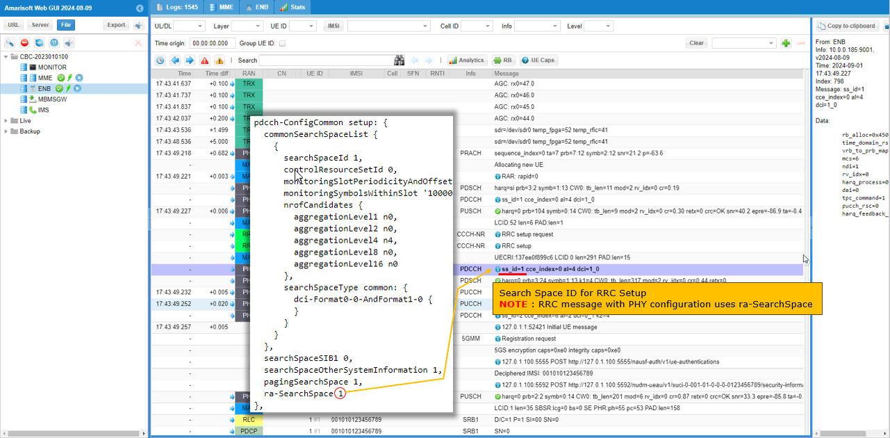
You will notice that RRC setup message is scheduled by PDCCH in ss_id configured in ra-SearchSpace which is a css (
The PDCCH ahead of the RRC setup row reads ss_id=1 cce_index=0 al=4 dci=1_0, which is the same search space, the same aggregation level and the same fallback DCI format the RAR used a moment earlier. The reason is straightforward once you look at what RRC Setup contains. It is the message that delivers pdcch-Config in the first place, so it cannot be scheduled on the dedicated search space that it is about to define.
The grant behind it is rb_alloc=0x450, mcs=6, ndi=1, rv_idx=0, harq_process=0, dai=0, tpc_command=1 and pucch_rsc=0. Those last four fields are the ones that separate a UE addressed grant from the RAR grant further up, which had no HARQ process, no DAI and no PUCCH resource to point at.
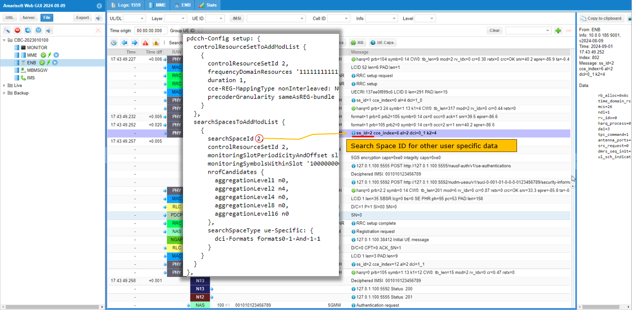
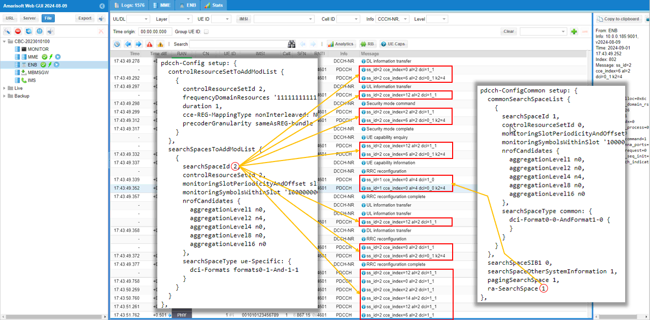
Other traffics (i.e, any traffic except SIB, RAR, RRC with PHY config) uses uss.
The PDCCH picked out here reads ss_id=2 cce_index=6 al=2 dci=0_1 k2=4, and it is scheduling the uplink for the registration and authentication exchange that runs after RRC setup complete. ss_id 2 is the searchSpaceId that pdcch-Config delivered in RRC Setup, al=2 is what al_index 1 selected from the uss n_candidates array, and dci=0_1 is the non fallback uplink format that dci_0_1_and_1_1 turned on.
cce_index has moved off 0 for the first time in this sequence. The common search space entries above all sat at cce_index 0 with a single aggregation level 4 candidate to work with, while this search space has 4 candidates at aggregation level 2 and the scheduler put this one at cce 6.
The grant is rb_alloc=0x6c, mcs=26, ndi=1, rv_idx=0, dai=3 and tpc_command=1, followed by antenna_ports, srs_request, dmrs_seq_init and ul_sch_indicator. Those last four are what format 0_1 buys you over the fallback format, and k2=4 is the slot offset from this PDCCH to the PUSCH it grants. Sub Test 2 below pushes everything back onto the common search space, and the same grants come out with a much shorter field list.
This shows a long sequence of transactions in a single shot showing which search space is used by each transaction. Just try to get familiar with the mapping and search space selection logic.
The message list is filtered on CCCH-NR and DCCH-NR here, which strips out the PHY chatter and leaves the RRC messages with the PDCCH entries that schedule them. Almost every PDCCH pair in the run is ss_id=2 at aggregation level 2, dci=1_1 for the downlink and dci=0_1 k2=4 for the uplink, and that covers DL information transfer, UL information transfer, Security mode command and complete, and UE capability enquiry and information. The cce_index on those rows moves around between 0, 2, 6, 12 and 14, which is the scheduler using the 4 candidates that aggregation level 2 gives it.
The one pair that breaks the pattern sits at the RRC reconfiguration and reads ss_id=1 cce_index=0 al=4 dci=1_0 and ss_id=1 cce_index=0 al=4 dci=0_0 k2=4. Search space 1 is the common search space that ra-SearchSpace points at, and this RRC reconfiguration carries physical layer configuration, so it falls back the same way RRC Setup did.
Reading down the ss_id column is the fastest check you can do on any of the tests that follow. Two ids show up, 1 and 2, and every row belongs to one of them for a reason you can name.
Sub Test 1 : Single Dedicated Coreset / Single Search Space - Explicit Configurations
The purpose of this Sub Test is basically same as the previous test but specified coreset_id, search_space_id explicitely. In this way, you can assign these ids as you like instead of getting them assigned automatically by gNB.
Just as high level descriptions :
- css maps to pdcch-ComfigCommon in SIB1
- uss maps to pdcch-Config in RRC Setup or RRC Reconfiguration
- n_candiates maps to nrofCanadiates in searchSpacesToAddModList
- You can explicitely specify which aggregation level(AL) should be used for which specific transactions in protocol sequence (e.g, rar_al_index for RAR, si_al_index for SIBs(Other SIBs), al_index for other general user traffcis etc)
I have used gnb-sa-coreset-ss-test1-subtest1.cfg which is copied and modified from gnb-sa-coreset-ss-test1.cfg
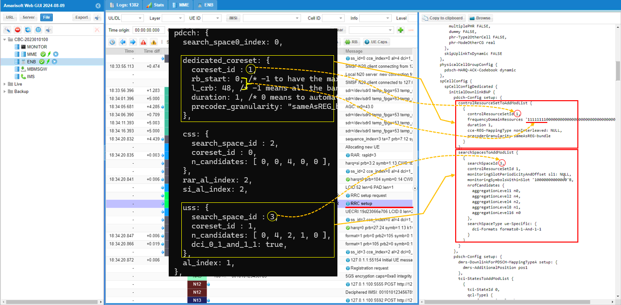
The -1 shortcuts are gone from dedicated_coreset in this file. It now reads coreset_id 1, rb_start 0, l_crb 48, duration 1 and precoder_granularity "sameAsREG_bundle", so the coreset is a stated 48 RB starting at RB 0 over 1 symbol instead of whatever the gNB would have worked out from the bandwidth.
css carries search_space_id 2 and coreset_id 0 with n_candidates [ 0, 0, 4, 0, 0 ], and uss carries search_space_id 3 and coreset_id 1 with n_candidates [ 0, 4, 2, 1, 0 ] and dci_0_1_and_1_1 true. coreset_id 0 on css keeps the common search space on coreset 0 as before, while coreset_id 1 on uss points at the dedicated coreset defined just above it. The ids you write here are the ids that come out in RRC, which is the whole point of the sub test.
The uss candidate array is also wider than the one in Test 1. Aggregation level 2 gets 4 candidates, level 4 gets 2 and level 8 gets 1, so the gNB has three levels to choose from on the dedicated search space. al_index 1 still selects level 2, and rar_al_index 2 and si_al_index 2 still select level 4 out of the css array, so the aggregation levels in the logs do not change even though the ids do.
Then perform the test and look into the logs.
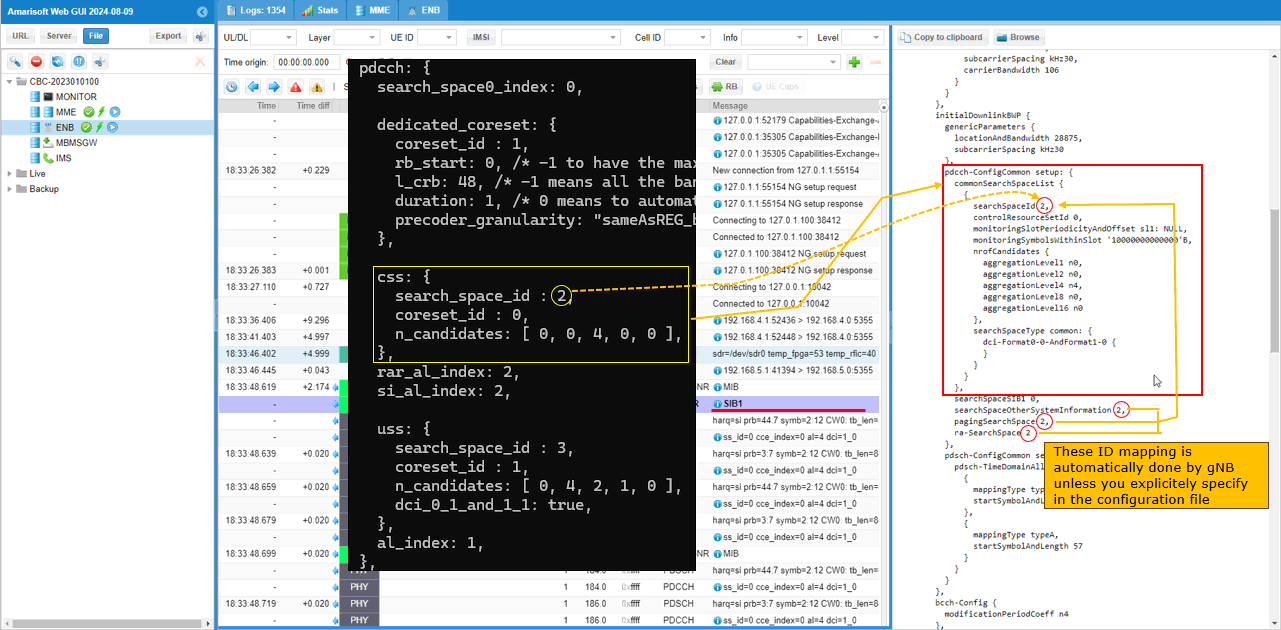
Frist let's take a look at how css parameter is mapped to RRC. It is mapped to pdcch-ConfigCommon in SIB1. css parameter (object) has many child paramters in it, but by default we usually specify agrregation level with the parameter n_candidates. n_candidates is mapped to nrofCandiates IE and each of the elements in n_candidates array maps to each elements of nrofCandidates IE.
Another important thing worth paying attention to are searchSpaceOtherSystempInformation, pagingSearchSpace and ra-SearchSpace in RRC. In the configuration file of this test, I haven't specified these value. In this case, those IEs uses the seachSpaceID specified in commonSearchSpaceList.
commonSearchSpaceList now comes out as searchSpaceId 2 instead of the 1 that Test 1 produced, and 2 is the search_space_id written into css. controlResourceSetId stays at 0 because css still points at coreset 0, and nrofCandidates is unchanged at aggregationLevel4 n4 with n0 everywhere else, since n_candidates was not touched.
The three ids underneath move with it. searchSpaceOtherSystemInformation, pagingSearchSpace and ra-SearchSpace all read 2 in this run where they read 1 in Test 1. They still follow whatever id is sitting in commonSearchSpaceList, so writing search_space_id in css is enough to move all three at once. searchSpaceSIB1 stays at 0 either way, because that one comes from MIB and not from this list.
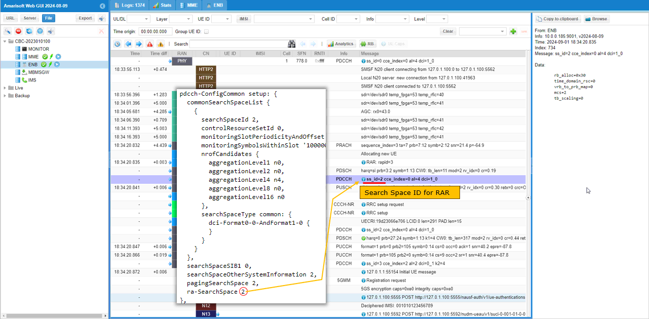
Now you can confirm that PDCCH for RAR uses ss_id configured in ra-SearchSpace IE in SIB. (
The PDCCH for the RAR reads ss_id=2 cce_index=0 al=4 dci=1_0 in this run, against ss_id=1 in Test 1. Only the id changed. The aggregation level is still 4 because rar_al_index is still 2, and the format is still the fallback dci=1_0 because a common search space carries nothing else.
The rest of the chain is the same as before, PRACH detected with sequence_index=3, RAR coming out as rapid=3, then RRC setup request and RRC setup, with a grant of rb_alloc=0x30, mcs=2 and tb_scaling=0.
Now let's take a look at how dedicated coreset and uss are configured and how they are mapped to RRC. High level mappings are as follows :
- rb_start and l_crb in configuration file are mapped to frequencyDomainResources in controlResourceSetToAddModList (
NOTE : 6 consecutive RBs corresponds to single bit '1' in frequencyDomainResources) - duration in configuration file maps to duration in controlResourceSetToAddModList
- precoder_granularity in configuration file maps to precoderGranularity in controlResourceSetToAddModList
controlResourceSetToAddModList comes out as controlResourceSetId 1, which is the coreset_id written in the file, and frequencyDomainResources is '1111111100000...'B. Eight bits are set and l_crb is 48, which is the one bit per 6 RB rule working in the direction you can actually check by hand. duration is 1 here because 1 was asked for, unlike Test 1 where 0 was asked for and 1 came back anyway.
searchSpacesToAddModList comes out as searchSpaceId 3 bound to controlResourceSetId 1, both taken straight from uss. nrofCandidates is aggregationLevel2 n4, aggregationLevel4 n2 and aggregationLevel8 n1, which is n_candidates [ 0, 4, 2, 1, 0 ] entry by entry, and searchSpaceType is ue-Specific with dci-Formats formats0-1-And-1-1.
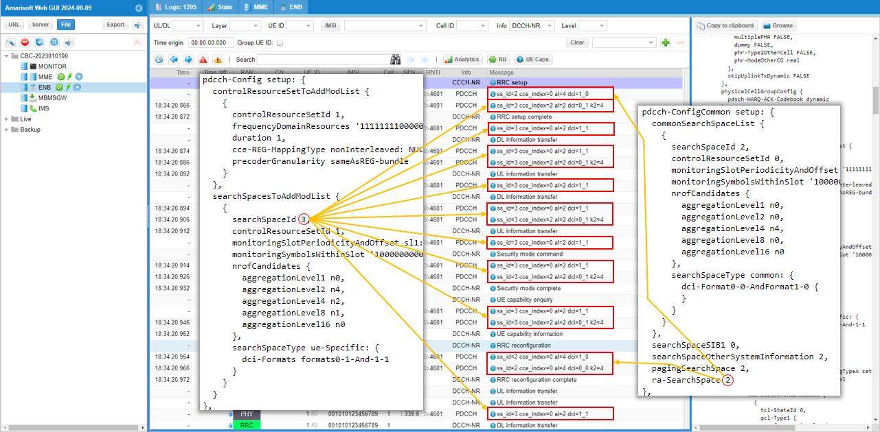
This shows a long sequence of transactions in a single shot showing which search space is used by each transaction. Just try to get familiar with the mapping and search space selection logic.
Two ids run down the ss_id column here, 3 and 2, against 2 and 1 in Test 1. Everything from DL and UL information transfer through Security mode command and complete to UE capability enquiry and information is scheduled on ss_id=3 at aggregation level 2, with dci=1_1 for the downlink and dci=0_1 k2=4 for the uplink, and the cce_index moves between 0, 2 and 6.
The RRC setup at the top and the RRC reconfiguration further down are the exceptions, both on ss_id=2 cce_index=0 al=4 with dci=1_0 and dci=0_0 k2=4. The selection rule has not changed at all from Test 1, only the numbers the rule lands on.
Sub Test 2 : Single Dedicated Coreset / Single Search Space - Explicit Configurations : Assigning css to all transactions
The purpose of this Sub Test is basically same as the previous test but specified coreset_id, search_space_id explicitely. In this way, you can assign these ids as you like instead of getting them assigned automatically by gNB.
Just as high level descriptions :
- css maps to pdcch-ComfigCommon in SIB1
- uss maps to pdcch-Config in RRC Setup or RRC Reconfiguration
- n_candiates maps to nrofCanadiates in searchSpacesToAddModList
- You can explicitely specify which aggregation level(AL) should be used for which specific transactions in protocol sequence (e.g, rar_al_index for RAR, si_al_index for SIBs(Other SIBs), al_index for other general user traffcis etc)
I have used gnb-sa-coreset-ss-test1-subtest2.cfg which is copied and modified from gnb-sa-coreset-ss-test1-subtest1.cfg
Everything down to al_index is identical to Sub Test 1. Same dedicated_coreset with coreset_id 1, rb_start 0, l_crb 48 and duration 1, same css with search_space_id 2 on coreset_id 0, same uss with search_space_id 3 on coreset_id 1 and n_candidates [ 0, 4, 2, 1, 0 ]. The only new lines are dl_search_space 2 and ul_search_space 2 at the bottom of the pdcch block.
These two name the search space that downlink and uplink grants should be sent on, and pointing both of them at 2 sends them to the common search space that css defines rather than to the uss. uss search_space_id 3 is still configured and still goes out in RRC Setup, it simply stops being used for scheduling.
There is an exception to how far these two parameters reach, and it is worth knowing before you read the logs. RAR and the RRC messages that carry physical layer configuration keep following ra-SearchSpace regardless of what you put here. In this particular file that is invisible because ra-SearchSpace also resolves to 2, which is exactly why the next sub test moves dl_search_space and ul_search_space somewhere else.
Then perform the test and look into the logs.
Frist let's take a look at how css parameter is mapped to RRC. It is mapped to pdcch-ConfigCommon in SIB1. css parameter (object) has many child paramters in it, but by default we usually specify agrregation level with the parameter n_candidates. n_candidates is mapped to nrofCandiates IE and each of the elements in n_candidates array maps to each elements of nrofCandidates IE.
Another important thing worth paying attention to are searchSpaceOtherSystempInformation, pagingSearchSpace and ra-SearchSpace in RRC. In the configuration file of this test, I haven't specified these value. In this case, those IEs uses the seachSpaceID specified in commonSearchSpaceList.
SIB1 is unchanged from Sub Test 1 in this run, which is the first thing to confirm. commonSearchSpaceList comes out as searchSpaceId 2 on controlResourceSetId 0 with aggregationLevel4 n4, and searchSpaceOtherSystemInformation, pagingSearchSpace and ra-SearchSpace all read 2 again.
dl_search_space and ul_search_space leave no trace anywhere in SIB1. They are gNB side scheduling parameters and there is no IE for them, so the only place their effect shows up is in the ss_id column of the PDCCH log.
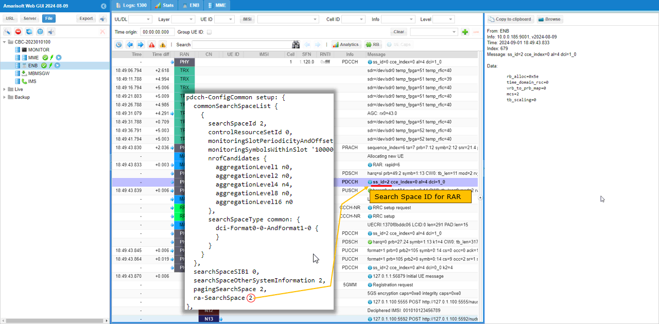
Now you can confirm that PDCCH for RAR uses ss_id configured in ra-SearchSpace IE in SIB. (
The RAR PDCCH reads ss_id=2 cce_index=0 al=4 dci=1_0, with PRACH detected at sequence_index=6 and the RAR coming out as rapid=6. The grant is rb_alloc=0x5e, mcs=2 and tb_scaling=0.
This row would look the same whether dl_search_space and ul_search_space were set or not, because RAR follows ra-SearchSpace and nothing else. Keep that in mind while reading the next two logs, where the same id 2 shows up on rows that did get there through dl_search_space and ul_search_space.
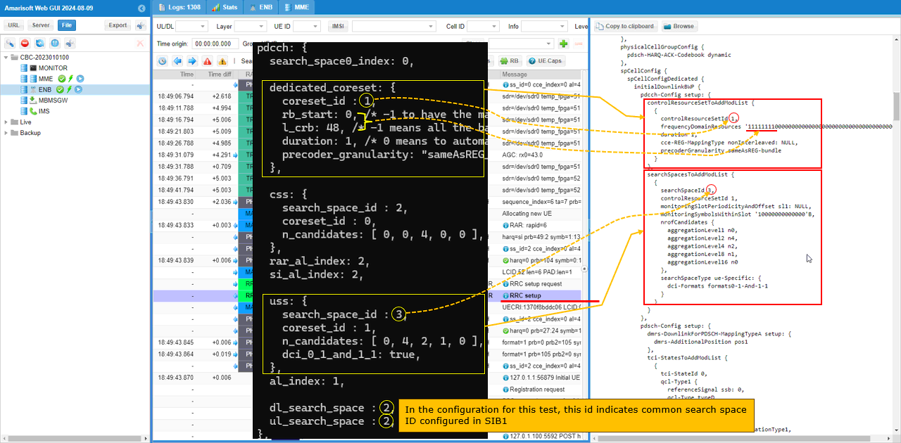
Now let's take a look at how dedicated coreset and uss are configured and how they are mapped to RRC. High level mappings are as follows :
- rb_start and l_crb in configuration file are mapped to frequencyDomainResources in controlResourceSetToAddModList (
NOTE : 6 consecutive RBs corresponds to single bit '1' in frequencyDomainResources) - duration in configuration file maps to duration in controlResourceSetToAddModList
- precoder_granularity in configuration file maps to precoderGranularity in controlResourceSetToAddModList
RRC Setup is byte for byte the same story as Sub Test 1. controlResourceSetId 1 with frequencyDomainResources '111111110000...'B and duration 1, then searchSpaceId 3 on controlResourceSetId 1 with aggregationLevel2 n4, aggregationLevel4 n2 and aggregationLevel8 n1, searchSpaceType ue-Specific and dci-Formats formats0-1-And-1-1.
The 2 that dl_search_space and ul_search_space carry is the common search space id from SIB1, not one of the ids in this list. So search space 3 is fully defined, handed to the UE, and then never scheduled on. If you had meant to move dedicated traffic to the dedicated search space you would have written 3 in both parameters, which is what the next sub test does.
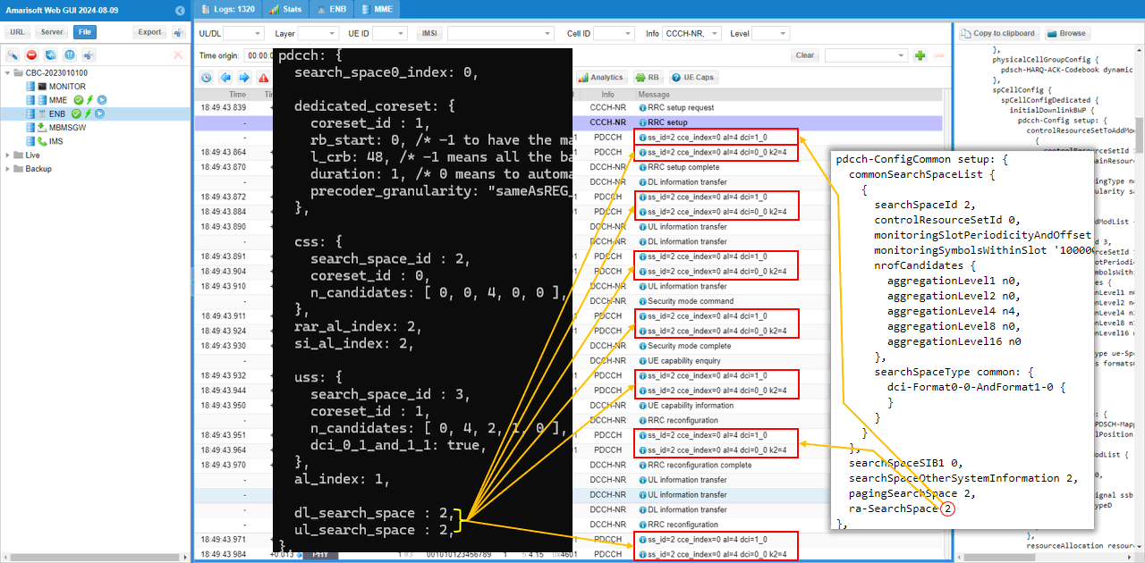
This shows a long sequence of transactions in a single shot showing which search space is used by each transaction. Just try to get familiar with the mapping and search space selection logic.
Every PDCCH pair in the run reads ss_id=2 cce_index=0 al=4, from RRC setup through DL and UL information transfer, Security mode command and complete, UE capability enquiry and information, and on to RRC reconfiguration. cce_index does not move off 0 on any of them.
The DCI formats moved as well, and that is the change that is easy to miss. These same rows carried dci=1_1 and dci=0_1 k2=4 in Sub Test 1 and they now carry dci=1_0 and dci=0_0 k2=4. A common search space only carries the fallback formats, so pulling dedicated traffic onto it pulls the format down too, and dci_0_1_and_1_1 true in uss has nothing left to act on. The aggregation level follows the css side for the same reason and comes out as 4 rather than the 2 that al_index asked for.
Sub Test 3 : Single Dedicated Coreset / Single Search Space - Explicit Configurations : Assigning both css and uss
The purpose of this Sub Test is basically same as the previous test but specified coreset_id, search_space_id explicitely. In this way, you can assign these ids as you like instead of getting them assigned automatically by gNB.
Just as high level descriptions :
- css maps to pdcch-ComfigCommon in SIB1
- uss maps to pdcch-Config in RRC Setup or RRC Reconfiguration
- n_candiates maps to nrofCanadiates in searchSpacesToAddModList
- You can explicitely specify which aggregation level(AL) should be used for which specific transactions in protocol sequence (e.g, rar_al_index for RAR, si_al_index for SIBs(Other SIBs), al_index for other general user traffcis etc)
I have used gnb-sa-coreset-ss-test1-subtest3.cfg which is copied and modified from gnb-sa-coreset-ss-test1-subtest2.cfg
Only two characters changed from the previous file. dl_search_space and ul_search_space now read 3 instead of 2, and 3 is the search_space_id that uss carries, so downlink and uplink grants for dedicated traffic are sent to the dedicated search space on coreset 1. Everything else is untouched, including css search_space_id 2 on coreset 0 and uss n_candidates [ 0, 4, 2, 1, 0 ] with dci_0_1_and_1_1 true.
The exception that was invisible in Sub Test 2 becomes visible with this file. RAR and the RRC messages carrying physical layer configuration still go to the common search space, so the logs below show ss_id 2 and ss_id 3 side by side and you can tell which parameter put each row where it is.
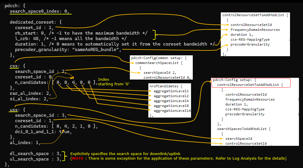
Then perform the test and look into the logs.
Frist let's take a look at how css parameter is mapped to RRC. It is mapped to pdcch-ConfigCommon in SIB1. css parameter (object) has many child paramters in it, but by default we usually specify agrregation level with the parameter n_candidates. n_candidates is mapped to nrofCandiates IE and each of the elements in n_candidates array maps to each elements of nrofCandidates IE.
Another important thing worth paying attention to are searchSpaceOtherSystempInformation, pagingSearchSpace and ra-SearchSpace in RRC. In the configuration file of this test, I haven't specified these value. In this case, those IEs uses the seachSpaceID specified in commonSearchSpaceList.
SIB1 is again unchanged, searchSpaceId 2 on controlResourceSetId 0 with aggregationLevel4 n4, and searchSpaceOtherSystemInformation, pagingSearchSpace and ra-SearchSpace all reading 2. Three sub tests in a row have produced the same SIB1, which is the point worth taking away from this log.
The PDCCH rows visible in the message list at this stage are all ss_id=0 cce_index=0 al=4 dci=1_0, because nothing but MIB and SIB1 is being sent yet and those use search space 0.
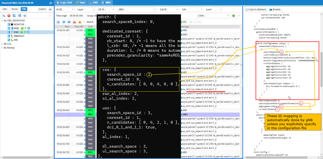
Now you can confirm that PDCCH for RAR uses ss_id configured in ra-SearchSpace IE in SIB. (
The RAR PDCCH reads ss_id=2 cce_index=0 al=4 dci=1_0, with PRACH at sequence_index=6 and RAR rapid=6, and a grant of rb_alloc=0x5e, mcs=2 and tb_scaling=0. dl_search_space and ul_search_space are both 3 in this file and this row is still on 2, which is the exception made concrete.
A few rows below it there is already a ss_id=3 cce_index=2 al=2 dci=0_1 k2=4 entry, so both search spaces are in use within the same handful of milliseconds.
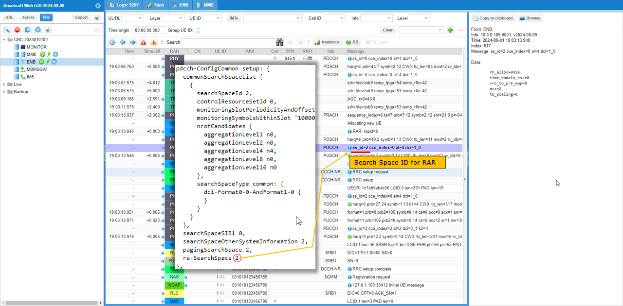
Now let's take a look at how dedicated coreset and uss are configured and how they are mapped to RRC. High level mappings are as follows :
- rb_start and l_crb in configuration file are mapped to frequencyDomainResources in controlResourceSetToAddModList (
NOTE : 6 consecutive RBs corresponds to single bit '1' in frequencyDomainResources) - duration in configuration file maps to duration in controlResourceSetToAddModList
- precoder_granularity in configuration file maps to precoderGranularity in controlResourceSetToAddModList
RRC Setup carries the same pair as the previous two sub tests, controlResourceSetId 1 with frequencyDomainResources '111111110000...'B and duration 1, then searchSpaceId 3 on controlResourceSetId 1 with aggregationLevel2 n4, aggregationLevel4 n2 and aggregationLevel8 n1, searchSpaceType ue-Specific and dci-Formats formats0-1-And-1-1.
The difference is that dl_search_space and ul_search_space now name this searchSpaceId 3 rather than the common one in SIB1. The RRC content did not have to change to make that happen, which is the part worth noticing. Everything the UE was told is identical to Sub Test 2 and only the gNB side scheduling decision moved.
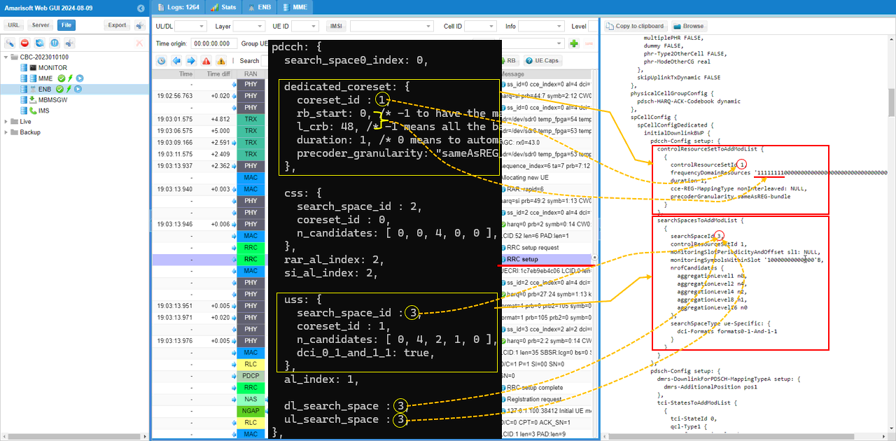
This shows a long sequence of transactions in a single shot showing which search space is used by each transaction. Just try to get familiar with the mapping and search space selection logic.
The ss_id column runs 3 for almost everything, at aggregation level 2 with dci=1_1 for the downlink and dci=0_1 k2=4 for the uplink, and cce_index moving between 0, 2 and 6. DL and UL information transfer, Security mode command and complete, and UE capability enquiry and information are all on 3.
The RRC reconfiguration in the middle is the one place where 2 appears, as ss_id=2 cce_index=0 al=4 dci=1_0 and ss_id=2 cce_index=0 al=4 dci=0_0 k2=4. Set this log next to the Sub Test 2 one and the two parameters have done exactly one thing, moved every row except that pair.
Test 2 : Multiple Dedicated Coreset / Multiple Search Space - Explicit Configurations : Assigning both css and uss
The purpose of this Sub Test is basically similar to previous test. Main difference is that I configured multiple dedicated and common coresents and search space. In this case, gNB can have more choices to select different search spaces depending on situations
Just as high level descriptions :
- css maps to pdcch-ComfigCommon in SIB1
- uss maps to pdcch-Config in RRC Setup or RRC Reconfiguration
- n_candiates maps to nrofCanadiates in searchSpacesToAddModList
- You can explicitely specify which aggregation level(AL) should be used for which specific transactions in protocol sequence (e.g, rar_al_index for RAR, si_al_index for SIBs(Other SIBs), al_index for other general user traffcis etc)
I have used gnb-sa-coreset-ss-test2.cfg which is copied and modified from gnb-sa-coreset-ss-test1-subtest3.cfg
In previous test, we used coreset 0 for all the css, but you can add another coresets for css as shown here. common_coreset is configured in pdcch-ConfigCommon.commonControlResourceSet IE.
The common_coreset block reads coreset_id 1, rb_start 6, l_crb 42, duration 1 and precoder_granularity "sameAsREG_bundle", and it comes out in SIB1 as commonControlResourceSet with controlResourceSetId 1, frequencyDomainResources '011111110000...'B, duration 1, cce-REG-MappingType nonInterleaved and precoderGranularity sameAsREG-bundle.
That bitmap is the clearest example of the rb_start and l_crb rule anywhere in this tutorial. rb_start 6 leaves the first bit clear, and l_crb 42 sets the next seven, one bit for every 6 RB. If you move rb_start to 12 the leading run of zeros becomes two bits, and if you cut l_crb to 36 the run of ones drops to six.
commonSearchSpaceList underneath now shows searchSpaceId 1 bound to controlResourceSetId 1, so the common search space is no longer sitting on coreset 0 the way it did in every earlier test. searchSpaceOtherSystemInformation, pagingSearchSpace and ra-SearchSpace all read 1 and follow it there, while searchSpaceSIB1 stays at 0 because SIB1 still has to be findable before any of this is known.
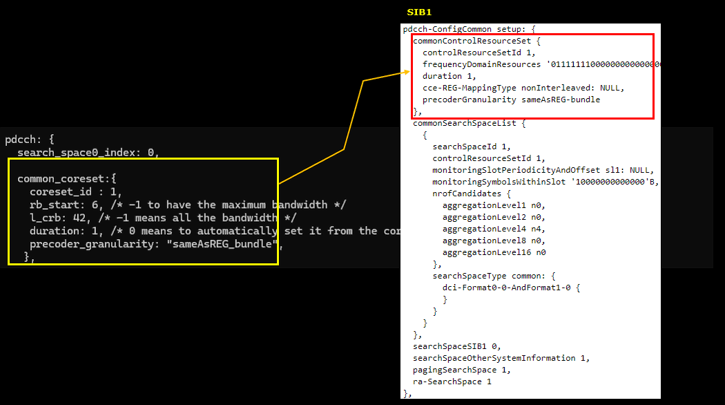
You can also configure multiple dedicated coresets. These dedicated_coreset is populated into pdcch-Config.controlResourceSetToAddModList in RRC Setup message.
dedicated_coreset is written as an array here, with square brackets around two blocks instead of the single braces the earlier tests used. The first is coreset_id 3 with rb_start 0, l_crb 48 and duration 1, and the second is coreset_id 4 with rb_start 24, l_crb 24 and duration 1, both with precoder_granularity "sameAsREG_bundle".
They arrive in RRC Setup as controlResourceSetId 3 with frequencyDomainResources '111111110000...'B and controlResourceSetId 4 with '000011110000...'B. Four leading zeros on the second one is rb_start 24, and the four ones after it is l_crb 24. Coreset 4 therefore sits entirely inside coreset 3, covering RB 24 to RB 48 of the 48 RB that coreset 3 spans, and there is nothing wrong with that. Coresets are allowed to overlap and it is a convenient way to give the scheduler a wide region and a narrow one to choose between.
searchSpacesToAddModList follows the same pattern in the same message, with one entry per search space rather than the single entry the earlier tests produced. The details of that half are easier to read against the css and uss blocks below.
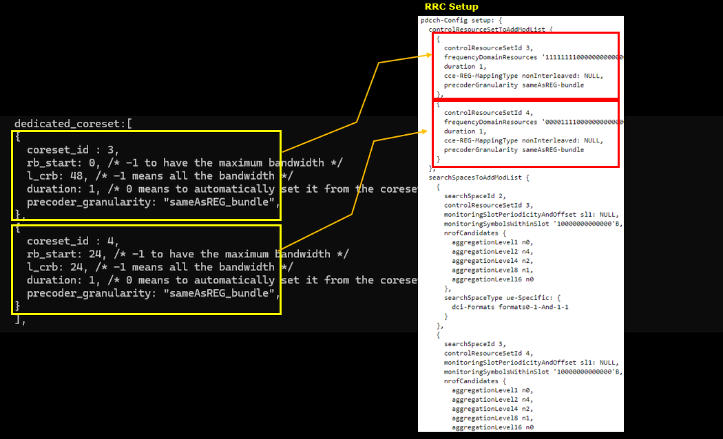
css configuration is same as in previous test and it is mapped to pdcch-ConfigCommon.commonSearchSpaceList in SIB1.
The css block keeps the shape it had all through Test 1. n_candidates is still [ 0, 0, 4, 0, 0 ] and rar_al_index and si_al_index are both still 2, so RAR and SIB scheduling still land on aggregation level 4. What is new is that css names search_space_id 1 and coreset_id 1, which puts the common search space on the common coreset that was added above rather than on coreset 0.
On the SIB1 side that comes out as commonSearchSpaceList with searchSpaceId 1 and controlResourceSetId 1, nrofCandidates aggregationLevel4 n4 with n0 everywhere else, and searchSpaceType common with dci-Format0-0-AndFormat1-0. searchSpaceOtherSystemInformation, pagingSearchSpace and ra-SearchSpace all read 1 below the list.
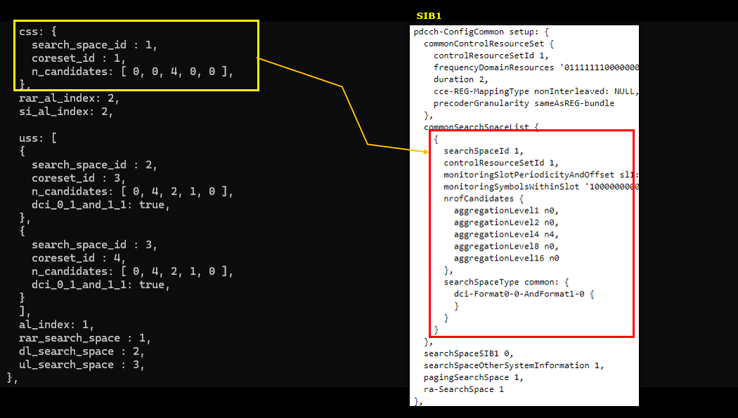
You can also configure multiple uss and these uss are populated into RRC Setup message.
uss is an array of two in this file. The first entry is search_space_id 2 on coreset_id 3 and the second is search_space_id 3 on coreset_id 4, and both carry n_candidates [ 0, 4, 2, 1, 0 ] with dci_0_1_and_1_1 true. They come out in RRC Setup as searchSpaceId 2 bound to controlResourceSetId 3 and searchSpaceId 3 bound to controlResourceSetId 4, each with aggregationLevel2 n4, aggregationLevel4 n2 and aggregationLevel8 n1, and each with searchSpaceType ue-Specific and dci-Formats formats0-1-And-1-1.
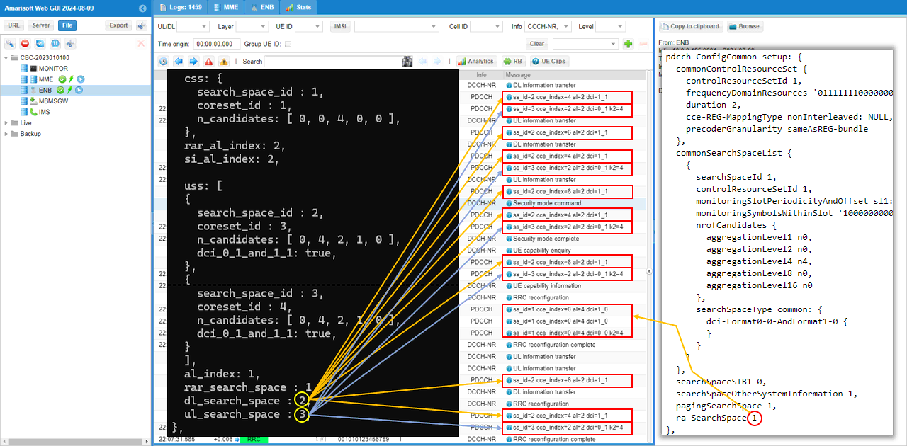
The three lines at the bottom are what make this test different from Sub Test 3. rar_search_space is 1, dl_search_space is 2 and ul_search_space is 3. This is the first file in the tutorial where downlink and uplink are pointed at different search spaces, so downlink grants go to search space 2 on coreset 3 and uplink grants go to search space 3 on coreset 4. Writing rar_search_space 1 also states out loud what the gNB had been filling in on its own up to now.
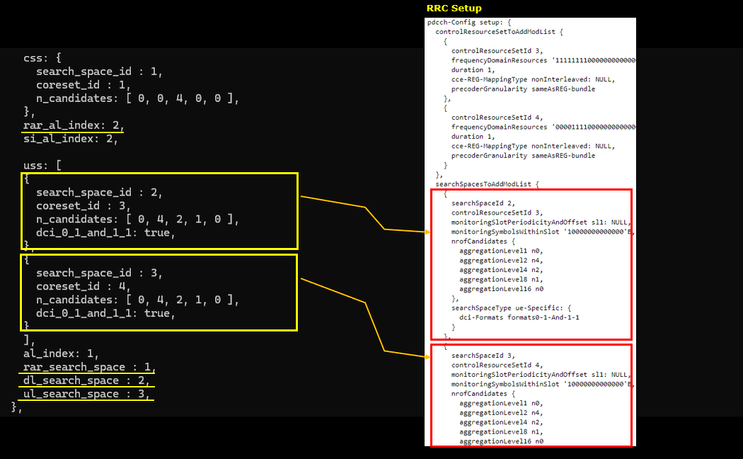
Then perform the test and look into the logs.
Frist let's take a look at how css parameter is mapped to RRC. It is mapped to pdcch-ConfigCommon in SIB1. css parameter (object) has many child paramters in it, but by default we usually specify agrregation level with the parameter n_candidates. n_candidates is mapped to nrofCandiates IE and each of the elements in n_candidates array maps to each elements of nrofCandidates IE.
Another important thing worth paying attention to are searchSpaceOtherSystempInformation, pagingSearchSpace and ra-SearchSpace in RRC. In the configuration file of this test, I haven't specified these value. In this case, those IEs uses the seachSpaceID specified in commonSearchSpaceList.
pdcch-ConfigCommon in this run opens with commonControlResourceSet, a field that was absent from every Test 1 log because there was no common_coreset to fill it. It reads controlResourceSetId 1, frequencyDomainResources '011111110000...'B, duration 1, cce-REG-MappingType nonInterleaved and precoderGranularity sameAsREG-bundle.
commonSearchSpaceList follows with searchSpaceId 1 on controlResourceSetId 1, nrofCandidates aggregationLevel4 n4 and searchSpaceType common with dci-Format0-0-AndFormat1-0, and then searchSpaceOtherSystemInformation 1, pagingSearchSpace 1 and ra-SearchSpace 1 underneath. The pair of ids is the thing to read together, because the search space and the coreset it points at are now both things you chose.
The PDCCH row that carries this SIB1 is still ss_id=0 cce_index=0 al=4 dci=1_0. Nothing in this test moves search space 0, and nothing can, since it is the one the UE finds from MIB.
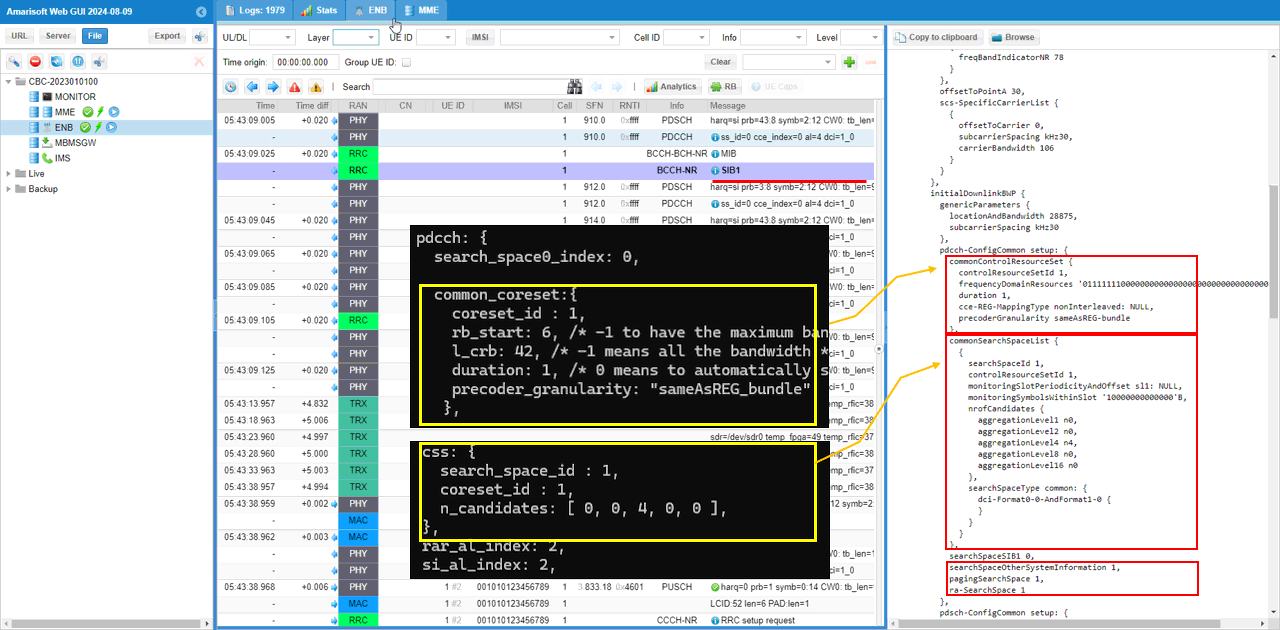
Now you can confirm that PDCCH for RAR uses ss_id configured in ra-SearchSpace IE in SIB. (
The RAR PDCCH reads ss_id=1 cce_index=0 al=4 dci=1_0, with PRACH at sequence_index=4 and RAR rapid=4, and a grant of rb_alloc=0x5e, mcs=2 and tb_scaling=0. This is the first test in the tutorial where rar_search_space was written into the configuration file, and 1 is the value that was written.
ra-SearchSpace in SIB1 also reads 1, so the two agree and there is nothing to tell apart from this log alone. The difference is that the id is now yours rather than the gNB's, which matters as soon as commonSearchSpaceList has more than one entry to choose from.
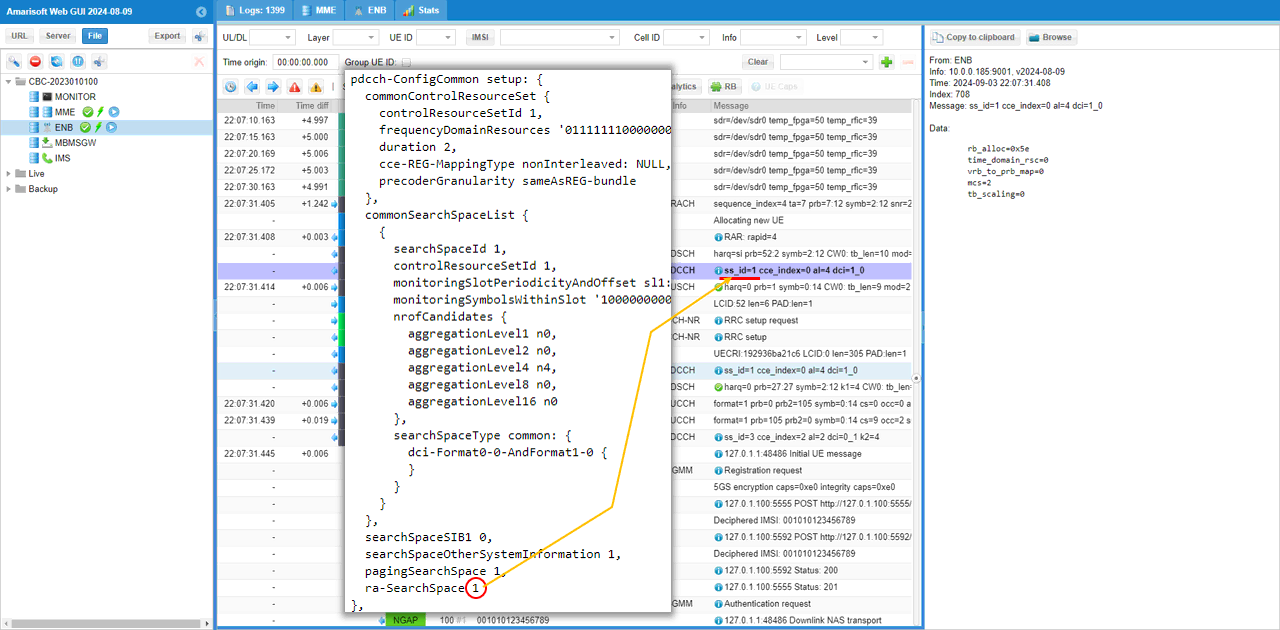
Now let's take a look at how dedicated coreset and uss are configured and how they are mapped to RRC. High level mappings are as follows :
- rb_start and l_crb in configuration file are mapped to frequencyDomainResources in controlResourceSetToAddModList (
NOTE : 6 consecutive RBs corresponds to single bit '1' in frequencyDomainResources) - duration in configuration file maps to duration in controlResourceSetToAddModList
- precoder_granularity in configuration file maps to precoderGranularity in controlResourceSetToAddModList
- The main point in this log is to show that multiple coreset and search spaces are configured.
controlResourceSetToAddModList comes back with two entries in this RRC Setup, controlResourceSetId 3 with frequencyDomainResources '111111110000...'B and controlResourceSetId 4 with '000011110000...'B, both with duration 1, cce-REG-MappingType nonInterleaved and precoderGranularity sameAsREG-bundle. Those are the two dedicated_coreset blocks in the order they were written.
searchSpacesToAddModList comes back with two entries as well, searchSpaceId 2 on controlResourceSetId 3 and searchSpaceId 3 on controlResourceSetId 4, each with aggregationLevel2 n4, aggregationLevel4 n2, aggregationLevel8 n1 and searchSpaceType ue-Specific with dci-Formats formats0-1-And-1-1. Reading the four boxes as two pairs is the quickest way to check this kind of configuration, one coreset with the search space that names it.
The UE is being told about both from this point on. Which of them actually gets used for a given grant is decided entirely on the gNB side by dl_search_space and ul_search_space, and that is what the last log below shows.
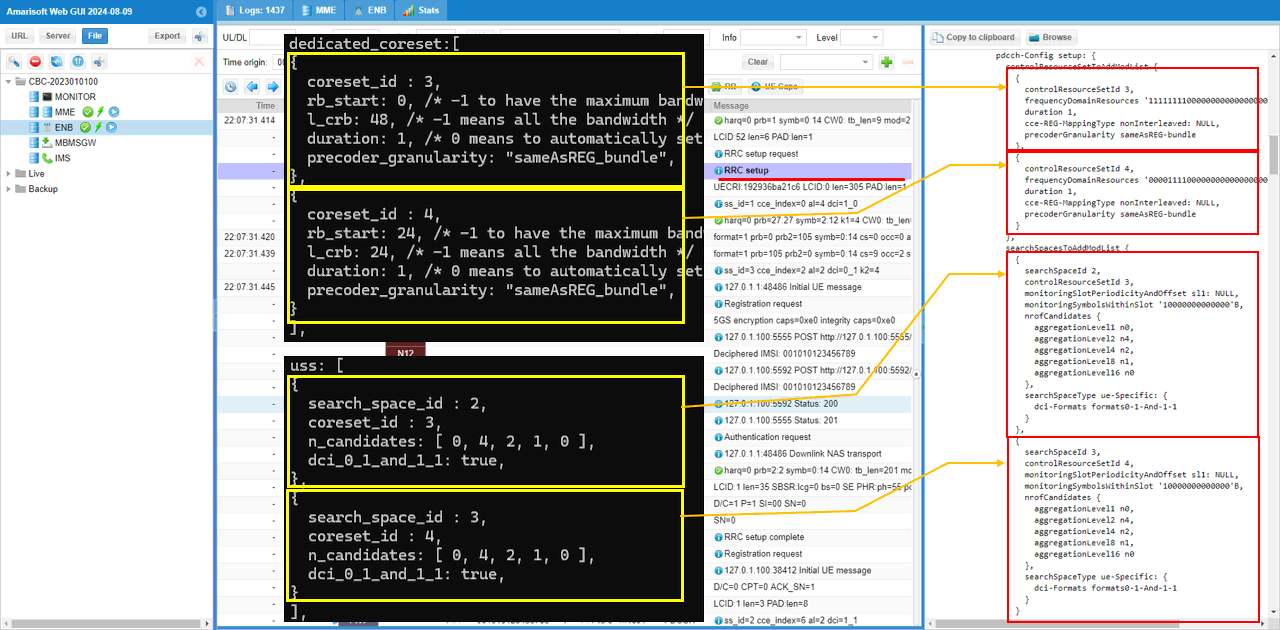
You see that the PDCCH for RRC Setup message is still using the css configured by ra-SearchSpace because this message carries PHY configurations.
The PDCCH ahead of the RRC setup row reads ss_id=1 cce_index=0 al=4 dci=1_0, the same search space the RAR used a moment earlier, with a grant of rb_alloc=0x43a, mcs=6, ndi=1, harq_process=0, dai=0, tpc_command=1, pucch_rsc=0 and harq_feedback_timing=3.
dl_search_space is 2 in this configuration and this row is on 1, which is the same exception you saw in Sub Test 3, now with a common coreset behind it instead of coreset 0. The rule has held unchanged across every test in this tutorial while the ids underneath it have moved four times.
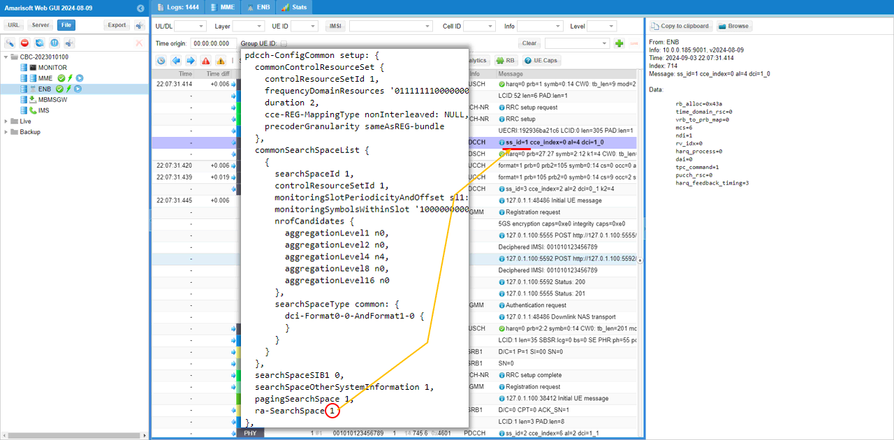
This shows a long sequence of transactions in a single shot showing which search space is used by each transaction. Just try to get familiar with the mapping and search space selection logic.
Three ids run down the ss_id column in this run instead of the two that every earlier test produced. The downlink rows read ss_id=2 cce_index=4 or 6 al=2 dci=1_1 and the uplink rows read ss_id=3 cce_index=2 al=2 dci=0_1 k2=4, and the two sit next to each other on the same DCCH-NR transaction, so the split is right there in adjacent lines. That is dl_search_space 2 and ul_search_space 3 doing exactly what they were set to do.
The RRC reconfiguration in the middle is on ss_id=1 cce_index=0 al=4, with dci=1_0 for the downlink and dci=0_0 k2=4 for the uplink, and neither of the two parameters reached it.
Search space 2 sits on coreset 3 and search space 3 sits on coreset 4, so downlink and uplink control for this UE are now being sent in different frequency regions of the carrier, coreset 3 spanning the low 48 RB and coreset 4 the 24 RB inside it. Splitting the two is the kind of thing you would do to test a UE against a narrow coreset on one direction only, and it needs both the multiple coreset definitions and the separate dl and ul parameters to set up.
RRC / NAS Signaling
SIB1 (SA)
: This is the SIB1 message sent by gNB to configure NR SA. (
{
message c1: systemInformationBlockType1: {
cellSelectionInfo {
q-RxLevMin -70,
q-QualMin -20
},
cellAccessRelatedInfo {
plmn-IdentityInfoList {
{
plmn-IdentityList {
{
mcc {
0,
0,
1
},
mnc {
0,
1
}
}
},
trackingAreaCode '000064'H,
cellIdentity '001234501'H,
cellReservedForOperatorUse notReserved
}
}
},
servingCellConfigCommon {
downlinkConfigCommon {
frequencyInfoDL {
frequencyBandList {
{
freqBandIndicatorNR 78
}
},
offsetToPointA 30,
scs-SpecificCarrierList {
{
offsetToCarrier 0,
subcarrierSpacing kHz30,
carrierBandwidth 106
}
}
},
initialDownlinkBWP {
genericParameters {
locationAndBandwidth 28875,
subcarrierSpacing kHz30
},
pdcch-ConfigCommon setup: {
commonControlResourceSet {
controlResourceSetId 1,
frequencyDomainResources '011111110000000000000000000000000000000000000'B,
duration 2,
cce-REG-MappingType nonInterleaved: NULL,
precoderGranularity sameAsREG-bundle
},
commonSearchSpaceList {
{
searchSpaceId 1,
controlResourceSetId 1,
monitoringSlotPeriodicityAndOffset sl1: NULL,
monitoringSymbolsWithinSlot '10000000000000'B,
nrofCandidates {
aggregationLevel1 n0,
aggregationLevel2 n0,
aggregationLevel4 n4,
aggregationLevel8 n0,
aggregationLevel16 n0
},
searchSpaceType common: {
dci-Format0-0-AndFormat1-0 {
}
}
}
},
searchSpaceSIB1 0,
searchSpaceOtherSystemInformation 1,
pagingSearchSpace 1,
ra-SearchSpace 1
},
pdsch-ConfigCommon setup: {
pdsch-TimeDomainAllocationList {
{
mappingType typeA,
startSymbolAndLength 53
},
{
mappingType typeA,
startSymbolAndLength 44
}
}
}
},
bcch-Config {
modificationPeriodCoeff n4
},
pcch-Config {
defaultPagingCycle rf128,
nAndPagingFrameOffset oneT: NULL,
ns one
}
},
uplinkConfigCommon {
frequencyInfoUL {
scs-SpecificCarrierList {
{
offsetToCarrier 0,
subcarrierSpacing kHz30,
carrierBandwidth 106
}
}
},
initialUplinkBWP {
genericParameters {
locationAndBandwidth 28875,
subcarrierSpacing kHz30
},
rach-ConfigCommon setup: {
rach-ConfigGeneric {
prach-ConfigurationIndex 160,
msg1-FDM one,
msg1-FrequencyStart 7,
zeroCorrelationZoneConfig 15,
preambleReceivedTargetPower -110,
preambleTransMax n7,
powerRampingStep dB4,
ra-ResponseWindow sl20
},
ssb-perRACH-OccasionAndCB-PreamblesPerSSB one: n8,
ra-ContentionResolutionTimer sf64,
prach-RootSequenceIndex l139: 1,
msg1-SubcarrierSpacing kHz30,
restrictedSetConfig unrestrictedSet
},
pusch-ConfigCommon setup: {
pusch-TimeDomainAllocationList {
{
k2 7,
mappingType typeA,
startSymbolAndLength 27
},
{
k2 4,
mappingType typeA,
startSymbolAndLength 27
},
{
k2 2,
mappingType typeA,
startSymbolAndLength 27
}
},
p0-NominalWithGrant -84
},
pucch-ConfigCommon setup: {
pucch-ResourceCommon 11,
pucch-GroupHopping neither,
p0-nominal -96
}
},
timeAlignmentTimerCommon infinity
},
ssb-PositionsInBurst {
inOneGroup '80'H
},
ssb-PeriodicityServingCell ms20,
tdd-UL-DL-ConfigurationCommon {
referenceSubcarrierSpacing kHz30,
pattern1 {
dl-UL-TransmissionPeriodicity ms5,
nrofDownlinkSlots 7,
nrofDownlinkSymbols 6,
nrofUplinkSlots 2,
nrofUplinkSymbols 4
}
},
ss-PBCH-BlockPower -40
},
ue-TimersAndConstants {
t300 ms1000,
t301 ms1000,
t310 ms1000,
n310 n1,
t311 ms30000,
n311 n1,
t319 ms1000
}
}
}
RRC Setup (SA)
: This is the RRC Setup message sent by gNB to configure NR SA. (
{
message c1: rrcSetup: {
rrc-TransactionIdentifier 0,
criticalExtensions rrcSetup: {
radioBearerConfig {
srb-ToAddModList {
{
srb-Identity 1
}
}
},
masterCellGroup {
cellGroupId 0,
rlc-BearerToAddModList {
{
logicalChannelIdentity 1,
servedRadioBearer srb-Identity: 1,
mac-LogicalChannelConfig {
ul-SpecificParameters {
priority 1,
prioritisedBitRate infinity,
bucketSizeDuration ms5,
logicalChannelGroup 0,
schedulingRequestID 0,
logicalChannelSR-Mask FALSE,
logicalChannelSR-DelayTimerApplied FALSE
}
}
}
},
mac-CellGroupConfig {
schedulingRequestConfig {
schedulingRequestToAddModList {
{
schedulingRequestId 0,
sr-TransMax n64
}
}
},
bsr-Config {
periodicBSR-Timer sf20,
retxBSR-Timer sf320
},
tag-Config {
tag-ToAddModList {
{
tag-Id 0,
timeAlignmentTimer infinity
}
}
},
phr-Config setup: {
phr-PeriodicTimer sf500,
phr-ProhibitTimer sf200,
phr-Tx-PowerFactorChange dB3,
multiplePHR FALSE,
dummy FALSE,
phr-Type2OtherCell FALSE,
phr-ModeOtherCG real
},
skipUplinkTxDynamic FALSE
},
physicalCellGroupConfig {
pdsch-HARQ-ACK-Codebook dynamic
},
spCellConfig {
spCellConfigDedicated {
initialDownlinkBWP {
pdcch-Config setup: {
controlResourceSetToAddModList {
{
controlResourceSetId 3,
frequencyDomainResources '111111110000000000000000000000000000000000000'B,
duration 1,
cce-REG-MappingType nonInterleaved: NULL,
precoderGranularity sameAsREG-bundle
},
{
controlResourceSetId 4,
frequencyDomainResources '000011110000000000000000000000000000000000000'B,
duration 1,
cce-REG-MappingType nonInterleaved: NULL,
precoderGranularity sameAsREG-bundle
}
},
searchSpacesToAddModList {
{
searchSpaceId 2,
controlResourceSetId 3,
monitoringSlotPeriodicityAndOffset sl1: NULL,
monitoringSymbolsWithinSlot '10000000000000'B,
nrofCandidates {
aggregationLevel1 n0,
aggregationLevel2 n4,
aggregationLevel4 n2,
aggregationLevel8 n1,
aggregationLevel16 n0
},
searchSpaceType ue-Specific: {
dci-Formats formats0-1-And-1-1
}
},
{
searchSpaceId 3,
controlResourceSetId 4,
monitoringSlotPeriodicityAndOffset sl1: NULL,
monitoringSymbolsWithinSlot '10000000000000'B,
nrofCandidates {
aggregationLevel1 n0,
aggregationLevel2 n4,
aggregationLevel4 n2,
aggregationLevel8 n1,
aggregationLevel16 n0
},
searchSpaceType ue-Specific: {
dci-Formats formats0-1-And-1-1
}
}
}
},
pdsch-Config setup: {
dmrs-DownlinkForPDSCH-MappingTypeA setup: {
dmrs-AdditionalPosition pos1
},
tci-StatesToAddModList {
{
tci-StateId 0,
qcl-Type1 {
referenceSignal ssb: 0,
qcl-Type typeD
}
}
},
resourceAllocation resourceAllocationType1,
rbg-Size config1,
prb-BundlingType staticBundling: {
bundleSize wideband
},
zp-CSI-RS-ResourceToAddModList {
{
zp-CSI-RS-ResourceId 0,
resourceMapping {
frequencyDomainAllocation row4: '100'B,
nrofPorts p4,
firstOFDMSymbolInTimeDomain 4,
cdm-Type fd-CDM2,
density one: NULL,
freqBand {
startingRB 0,
nrofRBs 108
}
},
periodicityAndOffset slots80: 1
}
},
p-ZP-CSI-RS-ResourceSet setup: {
zp-CSI-RS-ResourceSetId 0,
zp-CSI-RS-ResourceIdList {
0
}
}
}
},
firstActiveDownlinkBWP-Id 0,
uplinkConfig {
initialUplinkBWP {
pucch-Config setup: {
resourceSetToAddModList {
{
pucch-ResourceSetId 0,
resourceList {
0,
1,
2,
3,
4,
5,
6,
7
}
},
{
pucch-ResourceSetId 1,
resourceList {
8,
9,
10,
11
}
}
},
resourceToAddModList {
{
pucch-ResourceId 0,
startingPRB 105,
intraSlotFrequencyHopping enabled,
secondHopPRB 0,
format format1: {
initialCyclicShift 1,
nrofSymbols 14,
startingSymbolIndex 0,
timeDomainOCC 0
}
},
{
pucch-ResourceId 1,
startingPRB 105,
intraSlotFrequencyHopping enabled,
secondHopPRB 0,
format format1: {
initialCyclicShift 5,
nrofSymbols 14,
startingSymbolIndex 0,
timeDomainOCC 0
}
},
{
pucch-ResourceId 2,
startingPRB 105,
intraSlotFrequencyHopping enabled,
secondHopPRB 0,
format format1: {
initialCyclicShift 9,
nrofSymbols 14,
startingSymbolIndex 0,
timeDomainOCC 0
}
},
{
pucch-ResourceId 3,
startingPRB 105,
intraSlotFrequencyHopping enabled,
secondHopPRB 0,
format format1: {
initialCyclicShift 1,
nrofSymbols 14,
startingSymbolIndex 0,
timeDomainOCC 1
}
},
{
pucch-ResourceId 4,
startingPRB 105,
intraSlotFrequencyHopping enabled,
secondHopPRB 0,
format format1: {
initialCyclicShift 5,
nrofSymbols 14,
startingSymbolIndex 0,
timeDomainOCC 1
}
},
{
pucch-ResourceId 5,
startingPRB 105,
intraSlotFrequencyHopping enabled,
secondHopPRB 0,
format format1: {
initialCyclicShift 9,
nrofSymbols 14,
startingSymbolIndex 0,
timeDomainOCC 1
}
},
{
pucch-ResourceId 6,
startingPRB 105,
intraSlotFrequencyHopping enabled,
secondHopPRB 0,
format format1: {
initialCyclicShift 1,
nrofSymbols 14,
startingSymbolIndex 0,
timeDomainOCC 2
}
},
{
pucch-ResourceId 7,
startingPRB 105,
intraSlotFrequencyHopping enabled,
secondHopPRB 0,
format format1: {
initialCyclicShift 5,
nrofSymbols 14,
startingSymbolIndex 0,
timeDomainOCC 2
}
},
{
pucch-ResourceId 8,
startingPRB 1,
intraSlotFrequencyHopping enabled,
secondHopPRB 104,
format format2: {
nrofPRBs 1,
nrofSymbols 2,
startingSymbolIndex 0
}
},
{
pucch-ResourceId 9,
startingPRB 1,
intraSlotFrequencyHopping enabled,
secondHopPRB 104,
format format2: {
nrofPRBs 1,
nrofSymbols 2,
startingSymbolIndex 2
}
},
{
pucch-ResourceId 10,
startingPRB 1,
intraSlotFrequencyHopping enabled,
secondHopPRB 104,
format format2: {
nrofPRBs 1,
nrofSymbols 2,
startingSymbolIndex 4
}
},
{
pucch-ResourceId 11,
startingPRB 1,
intraSlotFrequencyHopping enabled,
secondHopPRB 104,
format format2: {
nrofPRBs 1,
nrofSymbols 2,
startingSymbolIndex 6
}
},
{
pucch-ResourceId 12,
startingPRB 105,
intraSlotFrequencyHopping enabled,
secondHopPRB 0,
format format1: {
initialCyclicShift 9,
nrofSymbols 14,
startingSymbolIndex 0,
timeDomainOCC 2
}
},
{
pucch-ResourceId 13,
startingPRB 1,
intraSlotFrequencyHopping enabled,
secondHopPRB 104,
format format2: {
nrofPRBs 1,
nrofSymbols 2,
startingSymbolIndex 8
}
}
},
format1 setup: {
},
format2 setup: {
maxCodeRate zeroDot25
},
schedulingRequestResourceToAddModList {
{
schedulingRequestResourceId 1,
schedulingRequestID 0,
periodicityAndOffset sl40: 8,
resource 12
}
},
dl-DataToUL-ACK {
8,
7,
6,
5,
4,
12,
11
}
},
pusch-Config setup: {
txConfig codebook,
dmrs-UplinkForPUSCH-MappingTypeA setup: {
dmrs-AdditionalPosition pos1,
transformPrecodingDisabled {
}
},
pusch-PowerControl {
msg3-Alpha alpha1,
p0-AlphaSets {
{
p0-PUSCH-AlphaSetId 0,
p0 0,
alpha alpha1
}
},
pathlossReferenceRSToAddModList {
{
pusch-PathlossReferenceRS-Id 0,
referenceSignal ssb-Index: 0
}
},
sri-PUSCH-MappingToAddModList {
{
sri-PUSCH-PowerControlId 0,
sri-PUSCH-PathlossReferenceRS-Id 0,
sri-P0-PUSCH-AlphaSetId 0,
sri-PUSCH-ClosedLoopIndex i0
}
}
},
resourceAllocation resourceAllocationType1,
codebookSubset nonCoherent,
maxRank 1,
uci-OnPUSCH setup: {
betaOffsets semiStatic: {
betaOffsetACK-Index1 9,
betaOffsetACK-Index2 9,
betaOffsetACK-Index3 9,
betaOffsetCSI-Part1-Index1 7,
betaOffsetCSI-Part1-Index2 7,
betaOffsetCSI-Part2-Index1 7,
betaOffsetCSI-Part2-Index2 7
},
scaling f1
}
},
srs-Config setup: {
srs-ResourceSetToAddModList {
{
srs-ResourceSetId 0,
srs-ResourceIdList {
0
},
resourceType aperiodic: {
aperiodicSRS-ResourceTrigger 1,
slotOffset 7
},
usage codebook,
p0 -84,
pathlossReferenceRS ssb-Index: 0
}
},
srs-ResourceToAddModList {
{
srs-ResourceId 0,
nrofSRS-Ports port1,
transmissionComb n2: {
combOffset-n2 0,
cyclicShift-n2 0
},
resourceMapping {
startPosition 0,
nrofSymbols n1,
repetitionFactor n1
},
freqDomainPosition 0,
freqDomainShift 9,
freqHopping {
c-SRS 22,
b-SRS 3,
b-hop 0
},
groupOrSequenceHopping neither,
resourceType aperiodic: {
},
sequenceId 500
}
}
}
},
firstActiveUplinkBWP-Id 0,
pusch-ServingCellConfig setup: {
}
},
pdcch-ServingCellConfig setup: {
},
pdsch-ServingCellConfig setup: {
nrofHARQ-ProcessesForPDSCH n16
},
csi-MeasConfig setup: {
nzp-CSI-RS-ResourceToAddModList {
{
nzp-CSI-RS-ResourceId 0,
resourceMapping {
frequencyDomainAllocation row2: '100'H,
nrofPorts p1,
firstOFDMSymbolInTimeDomain 3,
cdm-Type noCDM,
density one: NULL,
freqBand {
startingRB 0,
nrofRBs 108
}
},
powerControlOffset 0,
scramblingID 500,
periodicityAndOffset slots80: 1,
qcl-InfoPeriodicCSI-RS 0
},
{
nzp-CSI-RS-ResourceId 1,
resourceMapping {
frequencyDomainAllocation row1: '4'H,
nrofPorts p1,
firstOFDMSymbolInTimeDomain 5,
cdm-Type noCDM,
density three: NULL,
freqBand {
startingRB 0,
nrofRBs 108
}
},
powerControlOffset 0,
scramblingID 500,
periodicityAndOffset slots80: 1,
qcl-InfoPeriodicCSI-RS 0
},
{
nzp-CSI-RS-ResourceId 2,
resourceMapping {
frequencyDomainAllocation row1: '4'H,
nrofPorts p1,
firstOFDMSymbolInTimeDomain 9,
cdm-Type noCDM,
density three: NULL,
freqBand {
startingRB 0,
nrofRBs 108
}
},
powerControlOffset 0,
scramblingID 500,
periodicityAndOffset slots80: 1,
qcl-InfoPeriodicCSI-RS 0
},
{
nzp-CSI-RS-ResourceId 3,
resourceMapping {
frequencyDomainAllocation row1: '4'H,
nrofPorts p1,
firstOFDMSymbolInTimeDomain 5,
cdm-Type noCDM,
density three: NULL,
freqBand {
startingRB 0,
nrofRBs 108
}
},
powerControlOffset 0,
scramblingID 500,
periodicityAndOffset slots80: 2,
qcl-InfoPeriodicCSI-RS 0
},
{
nzp-CSI-RS-ResourceId 4,
resourceMapping {
frequencyDomainAllocation row1: '4'H,
nrofPorts p1,
firstOFDMSymbolInTimeDomain 9,
cdm-Type noCDM,
density three: NULL,
freqBand {
startingRB 0,
nrofRBs 108
}
},
powerControlOffset 0,
scramblingID 500,
periodicityAndOffset slots80: 2,
qcl-InfoPeriodicCSI-RS 0
}
},
nzp-CSI-RS-ResourceSetToAddModList {
{
nzp-CSI-ResourceSetId 0,
nzp-CSI-RS-Resources {
0
}
},
{
nzp-CSI-ResourceSetId 1,
nzp-CSI-RS-Resources {
1,
2,
3,
4
},
trs-Info true
}
},
csi-IM-ResourceToAddModList {
{
csi-IM-ResourceId 0,
csi-IM-ResourceElementPattern pattern1: {
subcarrierLocation-p1 s8,
symbolLocation-p1 4
},
freqBand {
startingRB 0,
nrofRBs 108
},
periodicityAndOffset slots80: 1
}
},
csi-IM-ResourceSetToAddModList {
{
csi-IM-ResourceSetId 0,
csi-IM-Resources {
0
}
}
},
csi-ResourceConfigToAddModList {
{
csi-ResourceConfigId 0,
csi-RS-ResourceSetList nzp-CSI-RS-SSB: {
nzp-CSI-RS-ResourceSetList {
0
}
},
bwp-Id 0,
resourceType periodic
},
{
csi-ResourceConfigId 1,
csi-RS-ResourceSetList csi-IM-ResourceSetList: {
0
},
bwp-Id 0,
resourceType periodic
},
{
csi-ResourceConfigId 2,
csi-RS-ResourceSetList nzp-CSI-RS-SSB: {
nzp-CSI-RS-ResourceSetList {
1
}
},
bwp-Id 0,
resourceType periodic
}
},
csi-ReportConfigToAddModList {
{
reportConfigId 0,
resourcesForChannelMeasurement 0,
csi-IM-ResourcesForInterference 1,
reportConfigType periodic: {
reportSlotConfig slots80: 9,
pucch-CSI-ResourceList {
{
uplinkBandwidthPartId 0,
pucch-Resource 13
}
}
},
reportQuantity cri-RI-PMI-CQI: NULL,
reportFreqConfiguration {
cqi-FormatIndicator widebandCQI,
pmi-FormatIndicator widebandPMI
},
timeRestrictionForChannelMeasurements notConfigured,
timeRestrictionForInterferenceMeasurements notConfigured,
groupBasedBeamReporting disabled: {
},
cqi-Table table2,
subbandSize value1
}
}
},
tag-Id 0
}
}
}
}
}
}